122 design exceptions and design variations · for projects using safety funds and developed to...
TRANSCRIPT

Topic #625-000-002 FDOT Design Manual
122 – Design Exceptions and Design Variations
122 Design Exceptions and Design Variations
122.1 General
The Department's design criteria and standards contained in the FDOT Design Manual are usually within the desirable ranges established by AASHTO. The values given have been accepted by the Federal Highway Administration (FHWA) and govern the design process. When it becomes necessary to deviate from the Department’s criteria, early documentation and approval are required. There are two approval processes used by designers: Design Exceptions and Design Variations.
When the Department’s criteria are not met, a Design Exception or Design Variation is required. This requirement applies to all entities affecting planning, design, construction and maintenance.
For projects using safety funds and developed to improve specific safety problems, only the elements identified under the scope of work for the safety improvement project are subject to these approval processes. Existing non-compliant features, within the limits of a safety improvement project do not require approval to remain, if the project does not create a non-compliant condition. The Safety Study must identify all applicable Variations and Exceptions required based on the proposed scope. For these projects, all applicable Design Variations and Design Exceptions must be approved prior to the beginning of the design phase.
For drainage projects, only elements identified in the scope of services for the drainage project are subject to these approval processes. The existing features, within the limits of the drainage project that do not meet design criteria, do not require approval to remain (if the project does not create a nonconforming condition).
Maintenance Resurfacing, Ride Rehabilitation and Skid Hazard Projects do not require Design Exceptions or Design Variations other than for ADA curb ramp requirements. If compliance with ADA curb ramp requirements is determined to be technically infeasible, documentation as a Design Variation is required. Maintenance Resurfacing Projects can only be programmed on routes that meet the requirements identified in Chapter 28 of the Work Program Instructions.
For Landscape Only projects, intersection sight distance Design Variations may be processed by the Responsible Landscape Architect of Record. For design projects with landscaping, intersection sight distance Design Variations must be processed by a Professional Engineer. In cases where intersection sight distance falls below stopping sight distance, a Design Exception for stopping sight distance must be processed by the respective professional according to the above guidelines.
1
January 1, 2018
Topic #625-000-002 FDOT Design Manual
122 – Design Exceptions and Design Variations
122.2 Identification
To allow time to research alternatives and begin the analysis and documentation activities, it is important that proper approval processes be identified as early as possible in the Planning and Design phases. This is preferably done during the PD&E process for major projects and the scope development process for minor projects. It is required that approval be obtained no later than Phase I submittal.
Design Exceptions are required when proposed design elements are below both the Department’s governing criteria and AASHTO’s new construction criteria for the Controlling Design Elements.
The 10 Controlling Design Elements for high speed (Design Speed ≥ 50 mph) roadways are:
(1) Design Speed
(2) Lane Width
(3) Shoulder Width
(4) Horizontal Curve Radius
(5) Superelevation Rate
(6) Stopping Sight Distance
(7) Maximum Grade
(8) Cross Slope
(9) Vertical Clearance
(10) Design Loading Structural Capacity
The 2 Controlling Design Elements for low speed (Design Speed < 50 mph) roadways are:
(1) Design Speed
(2) Design Loading Structural Capacity
FDM 122.5 provides AASHTO’s minimum requirements for the above elements.
Design Variations are required when proposed design elements are below the Department’s criteria and where a Design Exception is not required.
Modification for Non-Conventional Projects:
See RFP for additional requirements.
2
January 1, 2018

Topic #625-000-002 FDOT Design Manual
122 – Design Exceptions and Design Variations
122.3 Justification for Approval
Sufficient detail and explanation must be provided to those reviewing the request to justify approval. The 10 Controlling Design Elements are considered safety related and the strongest case possible must be made to lower these requirements. At some point, this justification may be used to defend design decisions made by the Department and the designer. All deviations from Department criteria and standards must be uniquely identified, located, and justified; no blanket approvals are given.
A strong case can be made if it can be shown that:
(1) The required criteria are not applicable to the site specific conditions.
(2) The project can be as safe by not following the criteria.
(3) The environmental or community needs prohibit meeting criteria.
Most often a case is made by showing the required criteria are impractical and the
proposed design wisely balances all design impacts. The impacts required for
documentation are:
(1) Safety and Operational performance
(2) Level of Service
(3) Right of Way impacts
(4) Community impacts
(5) Environmental impacts
(6) Costs
(7) Usability by all modes of transportation, Long term and cumulative effects on adjacent sections of roadway
A case should not be made based solely on the basis that:
(1) The Department can save money.
(2) The Department can save time.
(3) The proposed design is similar to other designs.
3
January 1, 2018
Topic #625-000-002 FDOT Design Manual
122 – Design Exceptions and Design Variations
122.4 Documentation for Approval
Supporting documentation that is generated during the approval process is to accompany each submittal.
Design Exceptions and Design Variations needing Central Office approval should include the following documentation:
(1) Submittal/Approval Letter (Form 122-A, see FDM 103)
(2) Project Description: general project information, location map, existing roadway characteristics, project limits (mileposts), county section number, work mix, objectives, and obstacles. Include any associated or future limitations that exist as a result of public or legal commitments.
(3) Project Schedule and Lifespan: Include the letting date and other important production dates associated with the project. Provide a discussion of whether the Design Exception is a temporary or permanent condition. Include any future work planned or programmed to address the condition.
(4) Exception/Variation Description:
(a) Specific design criteria that will not be met (AASHTO, Department value, or standard). Detailed explanation of why the criteria or standard cannot be complied with or is not applicable. Description of any proposed value for the project or location and why it is appropriate.
(b) A plan view, plan sheet, or aerial photo of the Design Exception location, showing right of way lines, and property lines of adjacent property. A photo of the area of the deficiency.
(c) Typical section or cross-section of the Design Exception location.
(d) The milepost and station location of the Design Exception.
(5) Alternative Designs Considered: meeting Department criteria, meeting AASHTO criteria, partial correction, and the no-build (existing) condition.
(6) Impacts of the Exception/Variation to:
(a) Safety Performance:
i. Description of the anticipated impact on safety, long and short term effects. Description of any anticipated cumulative effects.
ii. Summary of the most recent 5-year crash history including any pertinent crash reports.
4
January 1, 2018
Topic #625-000-002 FDOT Design Manual
122 – Design Exceptions and Design Variations
iii. For non-existing or proposed conditions, a comparison of the predicted or expected crash frequency should be included along with a discussion of the 5-year crash history.
(b) Operational Performance:
i. Description of the anticipated impact on operations, long and short term effects. Description of any anticipated cumulative effects.
ii. Traffic information: Amount and character of traffic using the facility.
iii. Compatibility of the design with adjacent sections of roadway.
(7) Effects on capacity (proposed criteria vs. AASHTO) using an acceptable capacity analysis procedure and calculate reduction for design year, level of service.
(8) Right-of-way
(9) Community
(a) Environment
(b) Usability by all modes of transportation
(10) Costs: Description of the anticipated costs associated with the Design Exception or Variation.
(11) Mitigation Measures: Description and explanation of any practical mitigation measures or alternatives that were considered and any selected treatments implemented on the project.
(12) Summary and Conclusions
122.5 AASHTO Controlling Elements
AASHTO criteria, required documentation, and mitigation strategies for the controlling elements is provided in the following sections. Detailed discussions on criteria and mitigation are provided in the AASHTO Green Book: A Policy on Geometric Design of Highways and Streets, 2011, and the FHWA Guide: Mitigation Strategies for Design Exceptions, July 2007. The AASHTO criteria provided are in no way intended to replace Department design criteria.
The criteria used for determining Design Exceptions on Interstate projects must be based on AASHTO’s A Policy on Design Standards Interstate System 2005.
5
January 1, 2018
Topic #625-000-002 FDOT Design Manual
122 – Design Exceptions and Design Variations
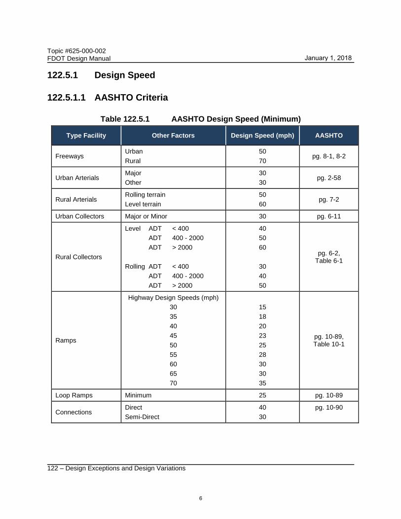
122.5.1 Design Speed
122.5.1.1 AASHTO Criteria
Table 122.5.1 AASHTO Design Speed (Minimum)
Type Facility Other Factors Design Speed (mph) AASHTO
Freeways Urban
Rural
50
70 pg. 8-1, 8-2
Urban Arterials Major
Other
30
30 pg. 2-58
Rural Arterials Rolling terrain
Level terrain
50
60 pg. 7-2
Urban Collectors Major or Minor 30 pg. 6-11
Rural Collectors
Level ADT < 400
ADT 400 - 2000
ADT > 2000
Rolling ADT < 400
ADT 400 - 2000
ADT > 2000
40
50
60
30
40
50
pg. 6-2, Table 6-1
Ramps
Highway Design Speeds (mph)
30
35
40
45
50
55
60
65
70
15
18
20
23
25
28
30
30
35
pg. 10-89, Table 10-1
Loop Ramps Minimum 25 pg. 10-89
Connections Direct
Semi-Direct
40
30
pg. 10-90
6
January 1, 2018

Topic #625-000-002 FDOT Design Manual
122 – Design Exceptions and Design Variations
122.5.1.2 Documentation
Provide the length of section with reduced design speed compared to the overall length of the project. Include any existing or proposed measures used within the transitions to adjacent roadway sections having higher or lower design (or operating) speeds.
122.5.1.3 Mitigation
A potential mitigation strategy is to use cross-sectional elements to reduce operating speeds to the design speed.
122.5.2 Lane Width
122.5.2.1 AASHTO Criteria
Table 122.5.2 AASHTO Lane Width (Minimum)
Type Facility Lane Width (feet) AASHTO
Freeway (including Auxiliary) 12 pg. 8-2, 10-76, DSIS pg.3 (1)
Rural Arterial 11 pg. 7-5, Table 7-3
Urban Arterial 10 pg. 7-29
Urban Collector 10 pg. 6-13
Rural Collector 10 pg. 6-6, Table 6-5
Low Speed 10 pg. 4-7
Residential 9 pg. 4-8
Auxiliary (Non-Freeway) 10 pp. 4-8, 6-13
Continuous TWLTL 10 pg. 4-8
Notes:
(1) DSIS = AASHTO’s A Policy on Design Standards Interstate System (January 2005).
122.5.2.2 Documentation
Provide locations of alternative routes that meet criteria and a proposal for handling drainage. Include a typical section or plan of the proposed signing and pavement markings associated with the lane width exception.
7
January 1, 2018

Topic #625-000-002 FDOT Design Manual
122 – Design Exceptions and Design Variations
122.5.2.3 Mitigation
Potential mitigation strategies for lane width are:
(1) Select optimal combination of lane and shoulder widths based on site characteristics to optimize safety and operations by distributing available cross-sectional width
(2) Signing to provide advanced warning of lane width reduction;
(3) To improve the ability to stay within the lane:
(a) Wide, recessed, or raised pavement markings
(b) Delineators
(c) Lighting
(d) Audible and vibratory treatment, (See FDM 210.4.6 for arterials and collectors. See FDM 211.4.4 for LA Facilities.)
(4) To improve the ability to recover if the driver leaves the lane:
(a) Paved or partially-paved shoulders
(b) Safety edge treatment
(5) To reduce crash severity if the driver leaves the roadway (See FDM 215):
(a) Remove or relocate fixed objects
(b) Traversable slopes
(c) Breakaway safety hardware
(d) Shield fixed objects and steep slopes
8
January 1, 2018

Topic #625-000-002 FDOT Design Manual
122 – Design Exceptions and Design Variations
122.5.3 Shoulder Width
122.5.3.1 AASHTO Criteria
Table 122.5.3 AASHTO Shoulder Widths (Minimum)
Type Facility Other Factors Median (feet) Right (feet) AASHTO
Freeway
4 lanes 4 paved 10 paved pg. 8-3
≥ 6 lanes 10 paved 10 paved pg. 8-3
Rural Arterial
ADT > 2000 8
pg. 7-5, Table 7-3 ADT 400-2000 6
ADT < 400 4
4 lane Divided 4 paved 8 pg. 7-13
6+ lane Divided 8 8 pg. 7-14
Urban Arterial Low Type (Gravel, Other) 2 pg. 4-10
High Type (Asphalt, Conc.) 10 pg. 4-10
Heavily Traveled/High Speed/High Trucks
10 pg. 4-10
Rural & Urban Collector
ADT > 2000 8
pg. 6-6, Table 6-5 ADT 1500-2000 6
ADT 400-1500 5
ADT < 400 2
9
January 1, 2018

Topic #625-000-002 FDOT Design Manual
122 – Design Exceptions and Design Variations
Table 122.5.4 AASHTO Bridge Widths (Minimum)
Type
Facility Other Factors Bridge Widths AASHTO
Freeway New Bridges Approach Roadway Width pg. 8-4
Rural Arterial
New Bridges (Short) Approach Roadway Width pg. 7-6
New Bridges (Long) (> 200 ft.)
Travel Lanes + 4 ft. each side pg. 7-6
Existing bridges Travel Lanes + 2 ft. each side pg. 7-6
Urban Arterial
New and Existing Bridges (Short)
Curb to curb width of street pg. 7-38
New and Existing Bridges (Long) without shoulders or parking on
arterial
Curb to curb width of street pg. 7-38
New and Existing Bridges (Long) with
shoulders or parking on arterial
Travel Lanes + 4 ft. each side pg. 7-38
Type
Facility Other Factors
Bridge Widths
AASHTO New or Reconstruction
To Remain
Rural and Urban
Collector
ADT Under 400 Traveled Way + 2 ft. each side (1) 22 ft. (2)
pg. 6-7, 8
Table 6-6,
Table 6-7
ADT 400-1500 Traveled Way + 3 ft. each side (1) 22 ft. (2)
ADT 1500-2000 Traveled Way + 4 ft. each side(1),(3) 24 ft. (2)
ADT > 2000 Approach Roadway Width (1),(3) 28 ft. (2)
Notes:
(1) If the approach roadway has paved shoulders, then the surfaced width must be carried across the bridge.
(2) Bridges longer than 100 ft. are to be analyzed individually.
(3) For bridges > 100 ft. in length, the minimum bridge width of traveled way plus 3 ft. on each side is acceptable.
10
January 1, 2018

Topic #625-000-002 FDOT Design Manual
122 – Design Exceptions and Design Variations
122.5.3.2 Documentation
Provide a proposal to address stalled vehicles, enforcement activities, emergency operations, and drainage in the documentation for the exception.
122.5.3.3 Mitigation
Potential mitigation strategies for shoulder width are:
(1) Select optimal combination of lane and shoulder width based on site characteristics to optimize safety and operations by distributing available cross-sectional width
(2) Signing to provide advanced warning of lane width reduction
(3) To improve the ability to stay within the lane:
(a) Wide, recessed or raised pavement markings
(b) Delineators
(c) Lighting
(d) Audible and vibratory treatment, (See FDM 210.4.6 for arterials and collectors. See FDM 211.4.4 for LA Facilities.)
(4) To improve the ability to recover if the driver leaves the lane:
(a) Paved or partially-paved shoulders
(b) Safety edge treatment
(5) To reduce crash severity if driver leaves the roadway (See FDM 215):
(a) Remove or relocate fixed objects
(b) Traversable slopes
(c) Breakaway safety hardware
(d) Shield fixed objects and steep slopes
11
January 1, 2018
Topic #625-000-002 FDOT Design Manual
122 – Design Exceptions and Design Variations
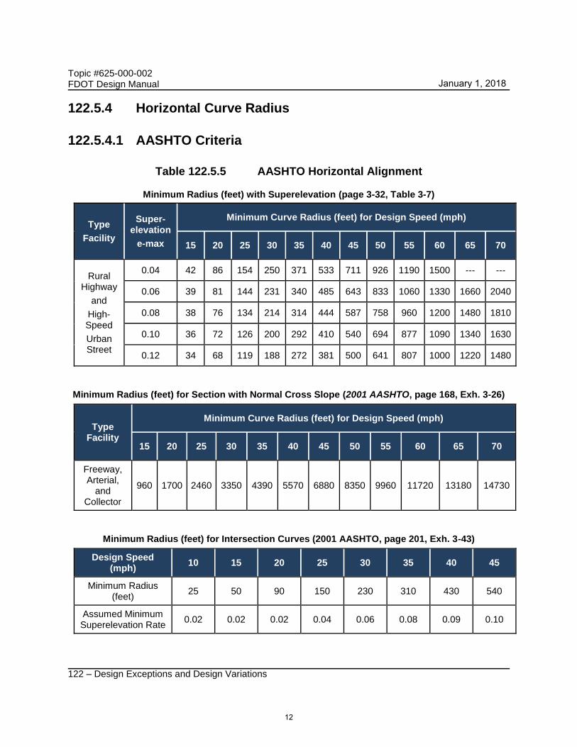
122.5.4 Horizontal Curve Radius
122.5.4.1 AASHTO Criteria
Table 122.5.5 AASHTO Horizontal Alignment
Minimum Radius (feet) with Superelevation (page 3-32, Table 3-7)
Type
Facility
Super-elevation
e-max
Minimum Curve Radius (feet) for Design Speed (mph)
15 20 25 30 35 40 45 50 55 60 65 70
Rural Highway
and
High-Speed
Urban Street
0.04 42 86 154 250 371 533 711 926 1190 1500 --- ---
0.06 39 81 144 231 340 485 643 833 1060 1330 1660 2040
0.08 38 76 134 214 314 444 587 758 960 1200 1480 1810
0.10 36 72 126 200 292 410 540 694 877 1090 1340 1630
0.12 34 68 119 188 272 381 500 641 807 1000 1220 1480
Minimum Radius (feet) for Section with Normal Cross Slope (2001 AASHTO, page 168, Exh. 3-26)
Type Facility
Minimum Curve Radius (feet) for Design Speed (mph)
15 20 25 30 35 40 45 50 55 60 65 70
Freeway, Arterial,
and Collector
960 1700 2460 3350 4390 5570 6880 8350 9960 11720 13180 14730
Minimum Radius (feet) for Intersection Curves (2001 AASHTO, page 201, Exh. 3-43)
Design Speed (mph)
10 15 20 25 30 35 40 45
Minimum Radius (feet)
25 50 90 150 230 310 430 540
Assumed Minimum Superelevation Rate
0.02 0.02 0.02 0.04 0.06 0.08 0.09 0.10
12
January 1, 2018
Topic #625-000-002 FDOT Design Manual
122 – Design Exceptions and Design Variations
122.5.4.2 Documentation
No additional documentation beyond what is covered in FDM 122.4 is required.
122.5.4.3 Mitigation
Potential mitigation strategies for horizontal curve radius are:
(1) To provide advanced warning:
(a) Signing
(b) Pavement marking messages
(c) Dynamic curve warning systems
(2) To provide delineation:
(a) Chevrons
(b) Post-mounted delineators
(c) Reflectors on barrier
(3) To improve the ability to stay within the lane:
(a) Widen the roadway
(b) Skid-resistant pavement
(c) Enhanced pavement markings
(d) Lighting;
(e) Audible and vibratory treatment, (See FDM 210.4.6 for arterials and collectors. See FDM 211.4.4 for LA Facilities.)
(4) To improve the ability to recover if driver leaves the lane:
(a) Paved or partially paved shoulders
(b) Safety edge
(5) To reduce the crash severity if driver leaves the roadway(See FDM 215):
(a) Remove or relocate fixed objects
(b) Traversable slopes
(c) Breakaway safety hardware
(d) Shield fixed objects and steep slopes
13
January 1, 2018
Topic #625-000-002 FDOT Design Manual
122 – Design Exceptions and Design Variations
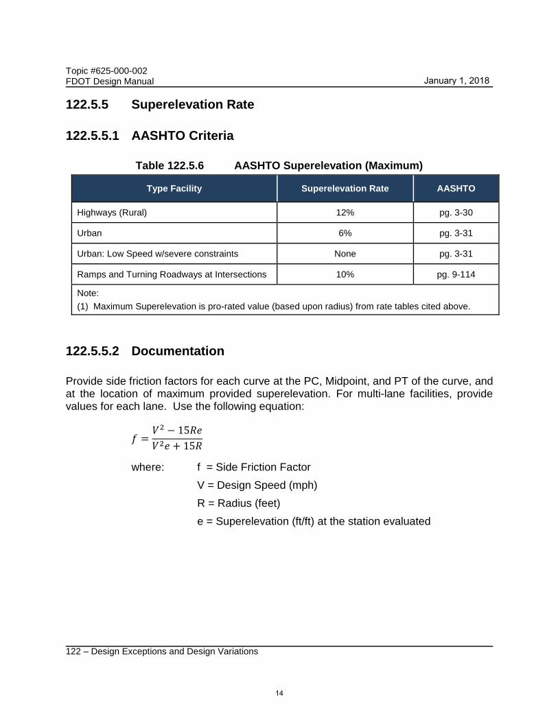
122.5.5 Superelevation Rate
122.5.5.1 AASHTO Criteria
Table 122.5.6 AASHTO Superelevation (Maximum)
Type Facility Superelevation Rate AASHTO
Highways (Rural) 12% pg. 3-30
Urban 6% pg. 3-31
Urban: Low Speed w/severe constraints None pg. 3-31
Ramps and Turning Roadways at Intersections 10% pg. 9-114
Note:
(1) Maximum Superelevation is pro-rated value (based upon radius) from rate tables cited above.
122.5.5.2 Documentation
Provide side friction factors for each curve at the PC, Midpoint, and PT of the curve, and at the location of maximum provided superelevation. For multi-lane facilities, provide values for each lane. Use the following equation:
𝑓 =𝑉2 − 15𝑅𝑒
𝑉2𝑒 + 15𝑅
where: f = Side Friction Factor
V = Design Speed (mph)
R = Radius (feet)
e = Superelevation (ft/ft) at the station evaluated
14
January 1, 2018

Topic #625-000-002 FDOT Design Manual
122 – Design Exceptions and Design Variations
122.5.5.3 Mitigation
Potential mitigation strategies for superelevation rate exceptions are:
(1) To provide advanced warning:
(a) Signing
(b) Pavement marking messages
(c) Dynamic curve warning systems
(2) To provide delineation:
(a) Chevrons
(b) Post-mounted delineators
(c) Reflectors on barrier
(3) To improve the ability to stay within the lane:
(a) Widen the roadway
(b) Skid-resistant pavement
(c) Enhanced pavement markings
(d) Lighting
(e) Audible and vibratory treatment, (See FDM 210.4.6 for arterials and collectors. See FDM 211.4.4 for LA Facilities.)
(4) To improve the ability to recover if driver leaves the lane:
(a) Paved or partially paved shoulders
(b) Safety edge
(5) To reduce the crash severity if driver leaves the roadway: (See FDM 215)
(a) Remove or relocate fixed objects
(b) Traversable slopes
(c) Breakaway safety hardware
(d) Shield fixed objects and steep slopes
15
January 1, 2018

Topic #625-000-002 FDOT Design Manual
122 – Design Exceptions and Design Variations
122.5.6 Stopping Sight Distance
122.5.6.1 AASHTO Criteria
Table 122.5.7 AASHTO Stopping Sight Distance (Minimum) (AASHTO page 3-4, Table 3-1)
Design Speed (mph)
15 20 25 30 35 40 45 50 55 60 65 70
Stopping Sight Distance (feet)
Computed for Design 80 115 155 200 250 305 360 425 495 570 645 730
Table 122.5.8 AASHTO Vertical Alignment (AASHTO Table 3-34, Table 3-36, and Table 6-3, and based on a 2’ object height)
Design Speed (mph)
Minimum K Value for Vertical Curves
Crest Sag
15 3 10
20 7 17
25 12 26
30 19 37
35 29 49
40 44 64
45 61 79
50 84 96
55 114 115
60 151 136
65 193 157
70 247 181
Note:
(1) Rate of vertical curvature, K, is the length of curve per percent algebraic difference of the intersecting grades. (K = L/A)
16
January 1, 2018

Topic #625-000-002 FDOT Design Manual
122 – Design Exceptions and Design Variations
Table 122.5.9 AASHTO Minimum Passing Sight Distance (AASHTO page 3-9, Table 3-4)
Design Speed (mph)
20 25 30 35 40 45 50 55 60 65 70
Passing Sight Distance (feet)
400 450 500 550 600 700 800 900 1000 1100 1200
122.5.6.2 Documentation
Provide profiles in the area of vertical alignment related Design Exception or Design
Variations for stopping sight distance. Provide plan views with sight triangles for
horizontal stopping sight distance evaluations.
122.5.6.3 Mitigation
Potential mitigation strategies for stopping sight distance are:
(1) To mitigate sight distance restrictions
(a) Signing and speed advisory plaques (crest vertical curves)
(b) Lighting
(c) Adjust placement of lane within the roadway cross section (horizontal)
(d) Cross-sectional elements to manage speed
(2) To improve the ability to avoid crashes:
(a) Cross-sectional elements
(b) Wider clear recovery area
(3) To improve driver awareness on approach to intersections:
(a) Advance warning signs
(b) Dynamic warning signs
(c) Larger or additional STOP/YIELD signs
(d) Intersection lighting
17
January 1, 2018

Topic #625-000-002 FDOT Design Manual
122 – Design Exceptions and Design Variations
122.5.7 Maximum Grade
122.5.7.1 AASHTO Criteria
Table 122.5.10 AASHTO Grades (Maximum)
Type Facility
Type Terrain
Grades (%) for Design Speed (mph)
AASHTO
30 35 40 45 50 55 60 65 70
Freeway (1) Level
Rolling
---
---
---
---
---
---
---
---
4
5
4
5
3
4
3
4
3
4
pg. 8-4,
Table 8-1
Rural Arterial Level
Rolling
---
---
---
---
5
6
5
6
4
5
4
5
3
4
3
4
3
4
pg. 7-4,
Table 7-2
Urban Arterial: Level
Rolling
8
9
7
8
7
8
6
7
6
7
5
6
5
6
---
---
---
---
pg. 7-29,
Table 7-4
Rural Collector(2) Level
Rolling
7
9
7
9
7
8
7
8
6
7
6
7
5
6
---
---
---
---
pg. 6-3,
Table 6-2
Urban Collector(2) Level
Rolling
9
11
9
10
9
10
8
9
7
8
7
8
6
7
---
---
---
---
pg. 6-12,
Table 6-8
Notes:
(1) Grades one percent steeper than the values shown may be used for extreme cases in urban areas where development precludes the use of flatter grades and for one-way downgrades.
(2) Short lengths of grade in rural and urban areas, such as grades less than 500 ft. in length, one-way downgrades, and grades on low-volume rural and urban collectors may be up to 2 percent steeper than the grades shown above.
122.5.7.2 Documentation
No additional documentation beyond what is in FDM 122.4 is required.
122.5.7.3 Mitigation
Potential mitigation strategies for maximum grade are:
(1) Signing to provide advanced warning
(2) To improve ability to stay within the lane:
(a) Enhanced pavement markings
18
January 1, 2018

Topic #625-000-002 FDOT Design Manual
122 – Design Exceptions and Design Variations
(b) Delineators
(c) Audible and vibratory treatment, (See FDM 210.4.6 for arterials and collectors. See FDM 211.4.4 for LA Facilities.)
(3) To improve ability to recover if driver leaves the roadway (See FDM 215):
(a) Paved or partially-paved shoulders
(b) Safety edge
(c) Remove or relocate fixed objects
(d) Traversable slopes
(e) Breakaway safety hardware
(f) Shield fixed objects
122.5.8 Cross Slope
122.5.8.1 AASHTO Criteria
Table 122.5.11 AASHTO Cross Slope
Type Facility Other Factors Minimum Maximum AASHTO
Freeways --- 0.015 0.025 (1) pg. 8-2
Arterials Rural
Urban
0.015
0.015
0.02
0.03
pg. 7-4
pg. 7-29
Divided Highways --- 0.015 0.02 (1) pg. 7-13
Collectors Rural
Urban
0.015
0.015
0.02
0.03
pg. 6-3
pg. 6-13
Shoulders
Paved
Gravel
Turf
0.02
0.04
0.06
0.06
0.06
0.08
pg. 4-11
pg. 4-11
pg. 4-11
Note:
(1) Values given are for up to two lanes in one direction. Additional outside lanes may have cross slopes of 0.03.
19
January 1, 2018

Topic #625-000-002 FDOT Design Manual
122 – Design Exceptions and Design Variations
122.5.8.2 Documentation
Provide a proposal for handling drainage and details on how the cross slope impacts intersections.
122.5.8.3 Mitigation
Potential mitigation strategies for deficient cross slope are:
(1) Signing to provide warning of slick pavement
(2) To improve surface friction:
(a) Pavement grooving (PCC Pavement)
(b) Open-graded friction courses (HMA pavement)
(3) To improve drainage:
(a) Transverse pavement grooving (PCC Pavement)
(b) Open-graded friction courses (HMA pavement)
(c) Pavement edge drains
(d) Modified shoulder cross slope to mitigate cross-slope break on the high side of superelevated curves.
20
January 1, 2018

Topic #625-000-002 FDOT Design Manual
122 – Design Exceptions and Design Variations
122.5.9 Vertical Clearance
122.5.9.1 AASHTO Criteria
Table 122.5.12 AASHTO Vertical Clearance (Minimum)
Type Facility Vertical Clearance (feet)(2) AASHTO
Freeways 16 (1),(4) pg. 8-4, 10-21
Arterials (New Structures): Rural
Urban
16 (1)
16 (1)
pg. 7-6, 10-21
pg. 7-38, 10-21
Arterials (Existing Structures): Rural
Urban
14
14
pg. 7-7, 10-21
pg. 7-38, 10-21
Other Highways 14 pg. 5-8, 8-4
Sign Trusses 17 pg. 7-7,38, 8-4
Pedestrian Overpass 17 pg. 7-7,38, 8-4
Tunnels: Freeways
Other Highways
16
14
pg. 4-53
pg. 4-53
Railroads 23 (3) pg. 10-22
Notes:
(1) 14 feet allowed in highly developed urban areas if alternate route has 16 feet.
(2) An allowance of 6 inches should be added to vertical clearance to accommodate future resurfacing.
(3) See FDM 220.3.4 and the latest version of American Railway Engineering and Maintenance-of-Way Association (AREMA) guidelines, or the design office of the high speed rail line of interest for specific high speed guidelines and specifications. Over Electrified Railroad, the minimum vertical clearance is 24 feet 3 inches. (See Topic No. 000-725-003: South Florida Rail Corridor Clearance.)
(4) Design Exceptions to the 16-ft vertical clearance standard on rural Interstate routes or on a single Interstate route through urban areas must be coordinated with Surface Deployment and Distribution Command Transportation Engineering Agency (SDDCTEA) as described in FDM 122.5.9.2.
122.5.9.2 Documentation
A written evaluation of the vertical clearance deficiency and recommendation by the State Office of Maintenance is required and should be attached to all Vertical Clearance Variations and Exceptions.
Provide locations of alternative routes that meet criteria.
21
January 1, 2018

Topic #625-000-002 FDOT Design Manual
122 – Design Exceptions and Design Variations
For Interstate Projects, the District is responsible for completing an Interstate Vertical Clearance Exception Coordination form, (http://www.fhwa.dot.gov/design/090415.cfm) for Design Exceptions to vertical clearance requirements above interstate facilities (mainlines and ramps). The District will submit the form to the Surface Deployment and Distribution Command Transportation Engineering Agency (SDDCTEA) via e-mail for approval, copying the FHWA Florida Division. Allow for 10 working days after SDDCTEA receipt for action before requesting notification of disposition (via email or fax). A copy of the approval must be provided with the Design Exception. A request for coordination must take place before the District Design Engineer can recommend the Design Exception.
122.5.9.3 Mitigation
Potential mitigation strategies for vertical clearance are:
(1) Signing to provide advance warning;
(2) To prevent impacts with low structures:
(a) Alternate routes
(b) Large vehicle restrictions.
(c) Bridge Jacking may be a consideration to address bridges with minor deficiencies.
22
January 1, 2018

Topic #625-000-002 FDOT Design Manual
122 – Design Exceptions and Design Variations
122.5.10 Design Loading Structural Capacity
122.5.10.1 AASHTO Criteria
Table 122.5.13 AASHTO Structural Capacity (Minimum Loadings)
Type Facility AASHTO
Freeways, Arterials, and Collectors
See AASHTO LRFD for minimum loadings.
122.5.10.2 Documentation
(1) Load rating calculations for the affected structure.
(2) Verification of safe load-carrying capacity (load rating) for State unrestricted legal loads or routine permit loads.
(3) Verification of Federal legal loads for bridges and tunnels on the Interstate.
(4) A written evaluation and recommendation by the Office of Maintenance.
122.5.10.3 Mitigation
Potential mitigation strategies for design loading structural capacity are determined on a case by case basis.
122.6 Crash Analysis
For areas with crash histories or when a benefit to cost analysis is required, provide a time value analysis between the benefit to society (quantified in dollars) and the costs to society (quantified in dollars) over the life of the Design Exception. The benefit to society is quantified by the savings associated with the projected reduction in crashes. The cost to society is a summary of the construction, operation, maintenance, and other costs anticipated over the life of the project. The Discount (interest) rate to be utilized in benefit/cost analysis is 4%.
Both Historical (HCM) and Predictive (RSAP and HSM) methods are acceptable for performance of a benefit/cost analysis.
23
January 1, 2018

Topic #625-000-002 FDOT Design Manual
122 – Design Exceptions and Design Variations
In accordance with the Department’s Highway Safety Manual Implementation Policy (Topic No. 000-500-001), “the transportation analyst is encouraged to use the Highway Safety Manual (HSM) methods, where applicable, to measure safety benefits from proposed improvements.”
122.6.1 Historical Crash Method (HCM)
This method can be used for sites with a crash history. It is the ratio (benefit/cost) of the estimated annual reduction in crash costs to the estimated annual increase in combined construction and maintenance costs. The annualized conversion will show whether the projected expenditure of funds for the crash benefit will exceed the direct cost for the improvement.
The HCM uses the Highway Safety Improvement Program Guideline (HSIPG) cost per crash by facility type in Table 122.6.1 to estimate benefit to society, while the cost to society is estimated by the expected cost of right of way, construction, and maintenance.
Table 122.6.1 FDOT Average Crash Costs by Facility Type
Type Facility
Divided Roadway Undivided Roadway
Urban Suburban Rural Urban Suburban Rural
2-3 Lanes $106,967 $186,651 $347,278 $121,332 $246,741 $506,164
4-5 Lanes $116,176 $213,668 $461,464 $110,657 $183,491 n/a
6+ Lanes $116,034 $154,430 $431,516 $31,282 n/a n/a
Interstate $145,263 n/a $331,210 n/a n/a n/a
Turnpike $141,607 n/a $277,755 n/a n/a n/a
Notes:
(1) Average Cost/Crash: $151,677
(2) The above values were derived from 2011 through 2015 traffic crash and injury severity data for crashes on state roads in Florida using the formulation described in FHWA Technical Advisory “Motor Vehicle Accident Costs”, T 7570.2, dated October 31, 1994 and from a memorandum from USDOT, Revised Departmental Guidance: Treatment of Economic Value of a Statistical Life (VSL) in the U.S. Department of Transportation Analyses, dated August 8, 2016 updating the value of life saved from $9.4 million to $9.6 million.
(3) Link to Revised Departmental Guidance 2013
24
January 1, 2018
Topic #625-000-002 FDOT Design Manual
122 – Design Exceptions and Design Variations
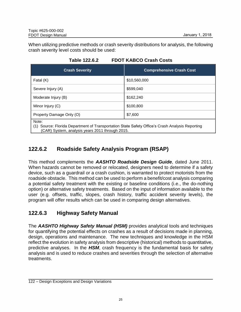
When utilizing predictive methods or crash severity distributions for analysis, the following crash severity level costs should be used:
Table 122.6.2 FDOT KABCO Crash Costs
Crash Severity Comprehensive Crash Cost
Fatal (K) $10,560,000
Severe Injury (A) $599,040
Moderate Injury (B) $162,240
Minor Injury (C) $100,800
Property Damage Only (O) $7,600
Note: (1) Source: Florida Department of Transportation State Safety Office’s Crash Analysis Reporting (CAR) System, analysis years 2011 through 2015.
122.6.2 Roadside Safety Analysis Program (RSAP)
This method complements the AASHTO Roadside Design Guide, dated June 2011. When hazards cannot be removed or relocated, designers need to determine if a safety device, such as a guardrail or a crash cushion, is warranted to protect motorists from the roadside obstacle. This method can be used to perform a benefit/cost analysis comparing a potential safety treatment with the existing or baseline conditions (i.e., the do-nothing option) or alternative safety treatments. Based on the input of information available to the user (e.g. offsets, traffic, slopes, crash history, traffic accident severity levels), the program will offer results which can be used in comparing design alternatives.
122.6.3 Highway Safety Manual
The AASHTO Highway Safety Manual (HSM) provides analytical tools and techniques for quantifying the potential effects on crashes as a result of decisions made in planning, design, operations and maintenance. The new techniques and knowledge in the HSM reflect the evolution in safety analysis from descriptive (historical) methods to quantitative, predictive analyses. In the HSM, crash frequency is the fundamental basis for safety analysis and is used to reduce crashes and severities through the selection of alternative treatments.
25
January 1, 2018

Topic #625-000-002 FDOT Design Manual
122 – Design Exceptions and Design Variations
The HSM includes Safety Performance Functions (SPFs) for many roadway segment and intersection applications. SPFs are equations used to estimate or predict the expected average crash frequency per year at a location as a function of traffic volume and roadway characteristics. Adjust SPFs to local conditions by applying calibration factors shown in Table 122.6.3. The use of HSMSPF and Crash Modification Factors (CMF), with an Empirical Bayes (EB) adjustment, provides research based solutions for use in Benefit/Cost comparisons. Crash distributions presented in Table 122.6.4 and KABCO costs as specified in Table 122.6.2 should be used in determining benefits from an HSM analysis.
Table 122.6.3 HSM Calibration Factors for Florida
Type Facility Abbreviation Calibration Factor (Cx)
FDOT Roadway Calibration Factors
Rural 2-lane Undivided R2U 1.00
4-lane Divided R4D 0.68
Urban
2-lane Undivided U2U 1.02
3-lane with a Center Two-Way Left Turn Lane U32LT 1.04
4-lane Undivided U4U .073
4-lane Divided U4D 1.63
5-lane with a Center Two-Way Left Turn Lane U52LT 0.70
FDOT Intersection Calibration Factors
Rural
2-lane 3-Leg Stop-Controlled RTL3ST 1.27
2-lane 4-Leg Stop-Controlled RTL4ST 0.74
2-lane 4-Leg Signalized RTL4SG 0.92
Multilane 3-Leg Stop-Controlled RML3ST 2.20
Multilane 4-Leg Stop-Controlled RML4ST 1.64
Multilane 4-Leg Signalized RML4SG 0.45
Urban
3-Leg Stop-Controlled Intersection USA3ST 1.14
4-Leg Stop-Controlled Intersection USA4ST 1.87
3-Leg Signalized w/o Ped. CMFs USA3SG w/o
Ped. 2.58
3-Leg Signalized w/ Ped. CMFs USA3SG w/ Ped. 2.50
4-Leg Signalized USA4SG 2.27
26
January 1, 2018

Topic #625-000-002 FDOT Design Manual
122 – Design Exceptions and Design Variations
Table 122.6.4 HSM Crash Distribution for Florida
Type Facility Abbreviation K A B C O
Rural Roadways
2-lane Undivided R2U 0.032 0.116 0.196 0.196 0.461
4-lane Undivided R4U 0.029 0.111 0.182 0.219 0.460
4-lane Divided R4D 0.030 0.112 0.206 0.197 0.453
Urban & Suburban Arterials
2-lane Undivided U2U 0.009 0.062 0.166 0.223 0.540
3-lane TWLTL U32LT N/A
4-lane Undivided U4U 0.005 0.037 0.126 0.209 0.623
4-lane Divided U4D 0.008 0.055 0.158 0.239 0.540
5-lane TWLTL U52LT N/A
Freeways
Rural 0.019 0.081 0.165 0.177 0.558
Urban 0.006 0.043 0.131 0.216 0.604
Ramps 0.004 0.039 0.124 0.223 0.610
All All Roadways and Ramps 0.008 0.049 0.141 0.224 0.577
Notes:
K – Fatality
A - Incapacitating Injury
B - Non-incapacitating Injury
C - Possible (or minor) Injury
O - Property Damage Only
Tools and spreadsheets for use with these analytical methods have been developed and are available on the following websites:
http://www.fdot.gov/safety/11A-SafetyEngineering/TransSafEng/HighwaySafetyManual.shtm
http://www.fdot.gov/roadway/QA/Tools.shtm
27
January 1, 2018

Topic #625-000-002 FDOT Design Manual
122 – Design Exceptions and Design Variations
122.7 Design Approval Request
122.7.1 Submittal Package
The submittal package is to include the following:
(1) Cover letter: Form 122-A (see FDM 103).
(2) Signed and Sealed Report: The signed and sealed documents including all required documentation and justification. Multiple design elements and signed and sealed reports may be included in one submittal package.
(3) Appendices (as needed): Include any support documentation to facilitate an understanding of the report. Supplemental documents do not alter the sealed analysis or design.
Sign and seal the report in accordance with FDM 130. A Submittal/Approval Letter (Form 122–A, see FDM 103) is to be attached to the Sealed Report and submitted to the District or Turnpike Design Engineer. The District or Turnpike Design Engineer then approves or denies the request and notifies the Responsible Engineer. When further approvals are required, the District or Turnpike Design Engineer will forward the Submittal/Approval Letter and Sealed Report to the State Roadway Design Office.
122.7.2 Design Exception Approval
The request will be reviewed by the State Roadway Design Engineer and may be forwarded for approval to the Chief Engineer, the State Structures Design Engineer, the Planning Office, and FHWA, as appropriate.
Each request will be reviewed on a case by case basis and approved on its merits. When approval is obtained, the State Roadway Design Office will email the disposition to the District or Turnpike Design Engineer along with the signed Submittal/Approval Letter. The State Roadway Design Office will keep an electronic copy filed under the assigned reference number.
When a request is denied, the State Roadway Design Office will notify the District or Turnpike Design Engineer of the disposition. Denied requests can be resubmitted when all deficiencies, noted in the denial notification, have been addressed. This may require only a new Submittal/Approval Letter if the Sealed Report does not need to be amended; however, if the Sealed Report requires revision, a new Sealed Report and attached Submittal/Approval Letter must be submitted.
28
January 1, 2018
Topic #625-000-002 FDOT Design Manual
122 – Design Exceptions and Design Variations
122.7.3 Design Variation Approval
Design Variations only require District approval unless identified as requiring Central Office approval in FDM 122.7.4 (see Table 122.7.1). Design Variations requiring Central Office approval from the Chief Engineer, State Roadway Design Engineer, and the State Structures Design Engineer (see FDM 122.7.4) follow the processes in FDM 122.7. Design Variations approved solely in the District may be submitted as a formal Design Variation or as a signed and sealed Design Memorandum for approval by the District or Turnpike Enterprise Design Engineer.
A formal Design Variation is required for any design criteria impacting clear zones, sight distance, or Americans with Disabilities Act (ADA) compliance. In these cases the Responsible Engineer or Professional attaches a Submittal Approval Letter (Form 122-A, see FDM 103) to the sealed report and submits the package to the District or Turnpike Design Engineer. The District or Turnpike Design Engineer then approves or denies the request and notifies the Responsible Engineer or Professional accordingly.
At a minimum, Design Variations are to include:
(1) Design criteria versus proposed criteria.
(2) Reason the design criteria are not appropriate.
(3) Justification for the proposed criteria.
(4) Review and evaluation of the most recent certified 5 years of crash history for Central Office approved Design Variations and formal District Design Variations.
(5) Background information which documents or justifies the request.
For Lateral Offset Design Variations, provide a tabulation of stations (or mileposts) and lateral offsets for aboveground fixed objects.
122.7.4 Signature Requirements
Obtain all required approvals as described in this section. Approvals from multiple individuals may be required for certain issues. The Director of Design must resolve any approval authority issues if conflicting objectives arise. Approval signatures are required by the following Department and FHWA personnel as specified:
Chief Engineer:
(1) Design Exceptions for Design Speed on SIS facilities, following review by the Chief Planner.
29
January 1, 2018
Topic #625-000-002 FDOT Design Manual
122 – Design Exceptions and Design Variations
(2) Design Variations for Design Speed on SIS facilities, following review by the Chief Planner.
FHWA Division Administrator:
(1) Design Exceptions on Projects of Division Interest (PODIs).
District (or Turnpike) Design Engineer:
(1) Design Exceptions
(2) Design Variations
State Roadway Design Engineer:
(1) Design Exceptions for elements other than Design Loading Structural Capacity.
(2) Design Variations involving the use of fencing around stormwater management facilities.
(3) Authority for approval of Design Exceptions and Design Variations on Florida Turnpike facilities has been delegated to the Turnpike Design Engineer by the State Roadway Design Engineer.
State Structures Design Engineer:
(1) Design Exceptions for Shoulder Width, Design Loading Structural Capacity of bridges and Vertical Clearance impacting Category 1 and 2 bridge structures.
(2) Design Variations for Shoulder Width, Design Loading Structural Capacity of bridges and Vertical Clearance impacting Category 2 structures.
(3) Design Variations for Design Loading Structural Capacity due to deficient load ratings impacting both Category 1 and 2 bridge structures.
(4) Design Variations for Traffic Railing impacting Category 1 and 2 bridge structures.
(5) Design Exceptions or Variations involving lateral offsets or vertical clearances for railroads not meeting the requirements of Rule 14-57 F.A.C. or the clearance criteria for the South Florida Rail Corridor (Topic No. 000-725-003 - South Florida Rail Corridor Clearance Policy for 25 KV service).
(6) Authority for approval of Design Exceptions and Design Variations for Shoulder Width and Vertical Clearance on Florida Turnpike facilities has been delegated to the Turnpike Design Engineer by the State Structures Design Engineer.
30
January 1, 2018

Topic #625-000-002 FDOT Design Manual
122 – Design Exceptions and Design Variations
District (or Turnpike) Structures Design Engineer:
(1) Design Exceptions for Shoulder Width, Design Loading Structural Capacity of all structural items and Vertical Clearance impacting Category 1 and 2 bridge structures.
(2) Design Variations for Shoulder Width, Design Loading Structural Capacity of all structural items and Vertical Clearance impacting Category 1 bridge structures.
31
January 1, 2018

Topic #625-000-002 FDOT Design Manual
122 – Design Exceptions and Design Variations
Table 122.7.1 Central Office Approvals
Design Element
State Roadway Design
Engineer
State Structures
Design Engineer
Chief Planner
Chief Engineer
Approval Approval Review Approval
Design Speed Exception X
Design Speed Exception-SIS X X X
Design Speed Variation-SIS X X
Lane Width Exception X
Shoulder Width Exception X X
Shoulder Width Variation (Category 2 Structures)
X
Design Loading Structural Capacity Exception
X
Design Loading Structural Capacity Variation
-Category 2 Structures X
-Deficient Load Ratings (Category 1 and 2 Structures)
X
-Traffic Railing (Category 1 and 2 Structures)
X
Vertical Clearance Exception X
-16’ for rural Interstate routes or single urban Interstate route
X
-All Category 1 and 2 Structures
X X
- RR-South Fla Rail Corridor X
Vertical Clearance Variation (Category 2 Structures)
X
Maximum Grade Exception X
Cross Slope Exception X
Superelevation Rate Exception X
32
January 1, 2018

Topic #625-000-002 FDOT Design Manual
122 – Design Exceptions and Design Variations
Table 122.7.1 Central Office Approvals (Cont.)
Design Element
State Roadway Design
Engineer
State Structures
Design Engineer
Chief Planner
Chief Engineer
Approval Approval Review Approval
Horizontal Curve Radius Exception
X
Stopping Sight Distance Exception
X
Lateral Offset Variation
-RR-South Fla Rail Corridor X
-Category 1 and 2 Structures X X
Lateral Offset Variation (Category 2 Structure)
X
Design Variation: Crossovers on Limited Access Facilities
X
Design Variation: Patterned Pavement Technical Special Provisions
X
Design Variation: Use of fencing around stormwater management facilities
X
Roundabout Designs-All X
Colored Bike Lane Assessments (The first 3 years after installation)
X
Design Variation: Community Aesthetic Features Non-Interstate
X
Design Variation: Community Aesthetic Features Interstate (FHWA)
X
33
January 1, 2018