(12) united states patent (10) patent no.: us 7.440,906 b1 ... · mil-hdbk-61, military handbook,...
TRANSCRIPT
USOO7440906B1
(12) United States Patent (10) Patent No.: US 7.440,906 B1 Wetzer et al. (45) Date of Patent: Oct. 21, 2008
(54) IDENTIFICATION, CATEGORIZATION, AND 5,778,381 A 7/1998 Sandifer
SSSINES&ERHAUL 5,826,236 A 10/1998 Narimatsu et al. 9
WORK ON MECHANICAL EQUIPMENT 5,877.961. A 3/1999 Moore
(75) Inventors: Michael Wetzer, Redwood City, CA (US); Gary R. Garrow, Burbank, CA (US); David P. West, II, Newnan, GA (Continued) (US); Patrick E. Weir, San Francisco, FOREIGN PATENT DOCUMENTS CA (US); Gary Ashby, Kent (GB); Charles P. Newton, III, Rock Hill, SC EP O 639815 A2 8, 1994 (US)
(73) Assignee: Accenture Global Services GmbH, Schauffhausen (CH) (Continued)
(*) Notice: Subject to any disclaimer, the term of this OTHER PUBLICATIONS patent is extended or adjusted under 35 U.S.C. 154(b) by 745 days. Knotts, Robert M. H. Civil Aircraft Maintenance and Support; Fault
Diagnosis from a Business Perspective, Journal of Quality in Main (21) Appl. No.: 09/946,095 tenance Engineering, vol. 5 No. 4, 1999, pp. 335-347, Dialog: File
15.* (22) Filed: Sep. 4, 2001
(Continued)
(51) enoo (2006.01) Primary Examiner Andre Boyce (52) U.S. Cl 70.5/8: 705/7: 705/10 (74) Attorney, Agent, or Firm—Brinks Hofer Gilson & Lione
(58) Field of Classification Search ............... ... 705/8 (57) ABSTRACT See application file for complete search history.
(56) References Cited
U.S. PATENT DOCUMENTS
4,744,026 A 5, 1988 Vanderbei 4,908,775 A 3/1990 Palusamy et al. 5,216,612 A 6, 1993 Cornett et al. 5,295,065 A 3/1994 Chapman et al. 5,311.562 A 5/1994 Palusamy et al. 5,331,579 A 7, 1994 Maguire, Jr. et al. 5,343,388 A 8, 1994 Wedelin 5.434,775 A 7, 1995 Sims et al. 5,596,507 A 1/1997 Jones et al. 5,630,070 A 5, 1997 Dietrich et al. 5,710,723 A 1/1998 Hoth et al. 5,737,728 A 4/1998 Sisley et al. 5,754.451 A 5, 1998 Williams
308 38 302
planned Maintenancel location Task Pointer
Location
Location
304
Plained Maintenans cation
scation
Location
306 Plated faintenance II cation
Location
Location
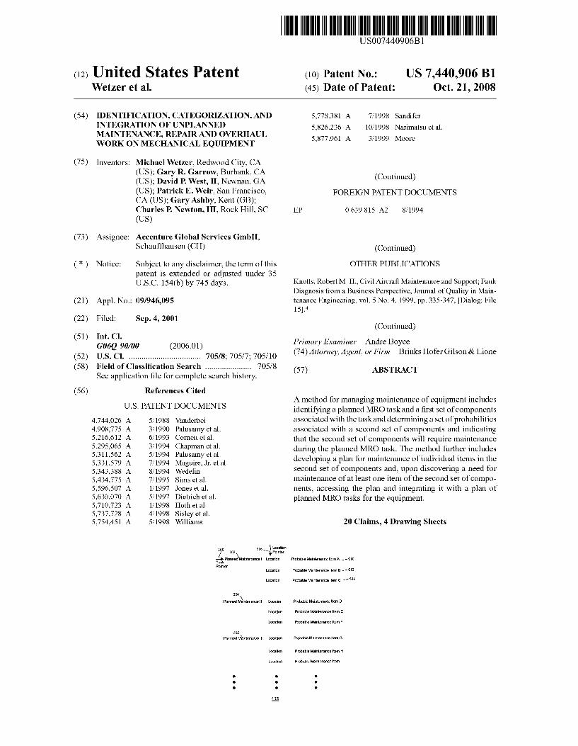
A method for managing maintenance of equipment includes identifying a planned MRO task and a first set of components associated with the task and determining a set of probabilities associated with a second set of components and indicating that the second set of components will require maintenance during the planned MRO task. The method further includes developing a plan for maintenance of individual items in the second set of components and, upon discovering a need for maintenance of at least one item of the second set of compo nents, accessing the plan and integrating it with a plan of planned MRO tasks for the equipment.
20 Claims, 4 Drawing Sheets
Probabe Mainterance item A -310
Probable Maintenance ?tem B -312
Probable Maintenance item C -
Probable Mainterarcsem D
Probabellariterance ten E
Probable Maintenance ites F
Pras Maintenancelter G
Probable Maintenancelter
Probable Mainterance term

US 7.440,906 B1 Page 2
5,890,133 5,897,629 5,918,219 5,920,846 5,931,878 5,963,911 5,970.437 5,970,466 5,987.474 5,995,915 6,006,171 6,014,633 6,038,539 6,067,486 6,078,912 6,101,481 6,110,214 6,128,543 6,154,735 6,175,934 6, 192,325 6,208.955 6,219,654 6,230,200 6,230,480 6,292,806 6,308, 162 6,321,207 6,349,274 6,418.361 6,496,814 6,571,158 6,580,982 6,594.786 6,598.940 6,606,546 6,671,593 6,678,716 6,684,136 6,691,006 6,691,064 6,691,244 6,701.298 6,714,829 6,732,028 6,738,748 6,801,820 6,820,038 6,980,959 7,031,941 7,058,587 7,085,766 7,124,059 7,231,374
2001/0053991 2002fOOO7225 2002fOO 10615 2002/0022984 2002fOO72988 2002.0143564 2002fO156692 2003/OOO9253 2003/OO36939 2003/0050824 2003/0216888 2004/OO19577 2005/O187838
U.S. PATENT DOCUMENTS
3, 1999 4, 1999 6, 1999 7, 1999 8, 1999
10, 1999 10, 1999 10, 1999 11, 1999 11, 1999 12, 1999
1, 2000 3, 2000 5, 2000 6, 2000 8, 2000 8, 2000
10, 2000 11, 2000
1, 2001 2, 2001 3, 2001 4, 2001 5, 2001 5, 2001 9, 2001
10, 2001 11, 2001 2, 2002 T/2002
12, 2002 5/2003 6, 2003 T/2003 T/2003 8, 2003
12, 2003 1, 2004 1, 2004 2, 2004 2, 2004 2, 2004 3, 2004 3, 2004 5, 2004 5, 2004
10, 2004 11, 2004 12, 2005 4, 2006 6, 2006 8, 2006
10, 2006 6, 2007
12, 2001 1, 2002 1, 2002 2, 2002 6, 2002
10, 2002 10, 2002
1, 2003 2, 2003 3, 2003
11, 2003 1, 2004 8, 2005
Ernst Shinagawa et al. Isherwood Storch et al. Chapin, Jr. Walker et al. Gorman et al. ............. TO2, 184 Detjen et al. Sandifer Reed et al. Vines et al. DeBusket al. Maruyama et al. Aragones et al. Buerger et al. Miller Klimasauskas Hitchner Crone Hershey et al. Piety et al. Provan et al. Ruffin Forecast et al. Rollins, III Sandifer Oulmet et al. Ye Kay et al. Sinex Busche Sinex Sinex Connelly et al. Sinex Sinex Sinex Prosanti, Jr. et al. Sinex Sinex Vroman ...................... TO2, 183 Kampe et al. Jutsen Wong Vanstory Wetzer Lilly et al. Wetzer et al. Garrow et al. Garrow et al. Horne Keith, Jr. .................... 707/101 Wetzer et al. Balasinski Bonabeau Costello et al. Jacobs Daniel et al. ................... 70.5/8 Aram Webb et al. Squeglia et al. McIntyre et al. Flores et al. ................... 70.5/8 Suermondt et al. Ridolfo ...................... TO2, 181
- - - - - - - - - 707/1 Abdel-Malek et al. Squeglia et al.
2007/02O3779 A1 8, 2007 Tveit et al.
FOREIGN PATENT DOCUMENTS
EP 1162557 A 12/2001 JP 6O1653.25 2, 1984 JP 62026510 A 2, 1987 JP O2O652O1 8, 1988 JP O2127952 11, 1988 JP O3264250 A 11, 1991 JP O4O25350 A 1, 1992 JP O7203120 12/1993 JP 08180654 12/1994 JP 8-263546 10, 1996 JP 9-050599 2, 1997 JP O706O449 2, 1997 JP 9034946 2, 1997 JP 10298.351 4f1997 JP O921.2555 A 8, 1997 JP 10-27200 1, 1998 JP 112101.06 1, 1998 JP 2OOOO15587 6, 1998 JP 2000-123O89 4/2000 JP 2000 124094 4/2000 JP 2001-34324 2, 2001 JP 20010925.20 4/2001 JP 2001-209676 8, 2001 WO WO 98.44439 10, 1998 WO WOO1/15001 3, 2001
OTHER PUBLICATIONS
McQueen, G., “Aircraft Maintenance.” Industrial Maintenance & Plant Operations, Aug. 1996. MIL-HDBK-61, Military Handbook, “Configuration Management Guidance.” Sep. 1997. IBM Technical Disclosure Bulletin, Computer-Aided Process Plan ning, v. 37, n.4B, p. 605-608, online), retrieved Sep. 11, 2005 via EAST (3 pages). Swanson, Computerized maintenance management systems: a study of system design. Production and Inventory Management Journal. 2" Qtr. 1997. v.38, n.2, p. 11-15 (5 pages). Dilger, Asset management, maintenance redefined, Manufacturing Systems, Jul. 1997, v.15, n. 7, p. 122-128, on-line), retrieved Sep. 8, 2005 via Dialog file 624.01 167091 (4 pages). Koch, Manage data to tame the maintenance tiger, Electrical World Mar/Apr. 2001, v.215, n.2, p.37. Ion-line), retrieved Sep. 8, 2005 via Dialog file 624:01 167091 (4 pages). Anonymous, maintenance mania, Manufacturing Systems, May 1998, v.16, n.5, p. 80-84, on-line), retrieved Sep. 8, 2005 via Dialog file 15:01650 138 (4 pages). Fulcher, ERP and PDM equals productivity, manufacturing systems, Aug. 1998, v.16, n.8, p. 36-40, online), retrieved Sep. 8, 2005 via Dialog file 15:01690148 (5 pages). Al-Sultan, Maintenance control via mathematical programming, Journal of Quality in Maintenance Engineering, 1995, v 1. n.3, p. 36-46, online), retrieved Sep. 8, 2005 via Dialog file 15:02271208 (9 pages). Avery, Datastream introduces new online buy system for MRO, Pur chasing, Nov. 18, 1999, v.127, n. 122 (1 page). Szwedo, Increasing productivity in an AS/RS maintenance depart ment, Production and Inventory Management Journal. 1" Qtr. 1995, v.36, n. 1, p. 76-81 (6 pages). Ho, An on-line system for aircraft maintenance, Journal of Systems Management, Sep. 1994, v.45, n.9, p. 24-27 (4 pages). Anonymous, Bell & Howell offers maintenance kits, today, Feb. 2000, v.22, n. 1, p. 10 (1 page). Kroenke, David M. Database Processing: Fundamentals, Design and Implementation, 1999 Prentice-Hall; NJ. pp. 3-23. International Search Report dated Oct. 4, 2002, for corresponding international application PCT/US02/09303. Written Opinion dated Mar. 5, 2003, for corresponding international application PCT/US02/09303.

US 7.440,906 B1 Page 3
International Search Report dated Dec. 28, 2001, for corresponding international application PCT/US01/32154. International Search Report dated Jan. 2, 2002, for corresponding international application PCT/US01/32576. Manny Gdalevitch, “MSG-3. The Intelligent Maintenance', Nov. 2000, Aircraft Maintenance Technology, pp. 1-6, retrieved from the web at: http://amtonline.com/publication/article.jsp?publd=l &id=1039. Parker A. Grant and James F. Mazeski; “Turbine Engine Mainte nance-Back to Basics'. Aircraft Maintenance Technology, Nov. 2000, retrieved from the web at: http://amtonline.com/publication? article.jsp?pubid=1&id=1035. Harry Fenton, “Magnetos Under PressureMagnetos Under Pres Sure'. Jul. 2000, retrieved from the web at: http://amtonline.com/ publication/article.jsp?publd=1&id=992. Jack Hessburg, “Scheduled Maintenance Tasks: Working through the development process with the Maintenance Steering Group'. Mar. 2000, retrieved from the web at: http://amtonline.com/publication? article.jsp?publd=1&id=950. Bill de Decker, “Save on Maintenance Costs', Mar. 2000, retrieved from the web at: http://amtonline.com/publication/article. jsp?pubid=1&id=952. Michael M. DiMauro, “Preventive Maintenance for Thrust Revers ers', Mar. 2000, retrieved from the web at: http://amtonline.com/ publication/article.jsp?pubid=1&id=947. Airman 2000: simplifying and optimizing aircraft maintenance, pp. 1-3, retrieved from the web at: http://www.content.airbusworld. convisites/Customerservices/html/acrobattfast29 p02 07 airman.pdf The prosecution history of U.S. Appl. No. 09/825,633 shown in the attached Patent Application Retrieval file wrapper document list, printed Mar. 7, 2008, including each substantive office action and applicant response. The prosecution history of U.S. Appl. No. 09/960,793 shown in the attached Patent Application Retrieval file wrapper document list, printed Mar. 7, 2008, including each substantive office action and applicant response. The prosecution history of U.S. Appl. No. 09/947,136 shown in the attached Patent Application Retrieval file wrapper document list,
printed Mar. 7, 2008, including each substantive office action and applicant response. The prosecution history of U.S. Appl. No. 09/947.024 shown in the attached Patent Application Retrieval file wrapper document list, printed Mar. 7, 2008, including each substantive office action and applicant response. The prosecution history of U.S. Appl. No. 09/946,894 shown in the attached Patent Application Retrieval file wrapper document list, printed Mar. 7, 2008, including each substantive office action and applicant response. The prosecution history of U.S. Appl. No. 09/946,093 shown in the attached Patent Application Retrieval file wrapper document list, printed Mar. 7, 2008, including each substantive office action and applicant response. The prosecution history of U.S. Appl. No. 09/946,032 shown in the attached Patent Application Retrieval file wrapper document list, printed Mar. 7, 2008, including each substantive office action and applicant response. The prosecution history of U.S. Appl. No. 09/946,160 shown in the attached Patent Application Retrieval file wrapper document list, printed Mar. 7, 2008, including each substantive office action and applicant response. The prosecution history of U.S. Appl. No. 10/799,914 shown in the attached Patent Application Retrieval file wrapper document list, printed Mar. 7, 2008, including each substantive office action and applicant response. The prosecution history of U.S. Appl. No. 09/947, 157 shown in the attached Patent Application Retrieval file wrapper document list, printed Apr. 2, 2008, including each Substantive office action and applicant response. Vijayan, Jaikumar, “Fault-Tolerant Computing”. Computerworld vol. 34, 1 page Issue 47, Mar, Apr. 2000. Morris Cohen et al., “Optimizer: IBM's Multi-Echelon Inventory System for Managing Service Logistics'. The Institute of Manage ment Sciences, pp. 65-82, Jan. to Feb. 1990.
* cited by examiner

U.S. Patent
Technician User Interface
110
4ES Scheduler
Oct. 21, 2008
114
106
f 102
Sheet 1 of 4 US 7.440,906 B1
Planned Work Planned Work Probable Geography Findings Locator
122 Work Description
Library
Equipment Geography Descriptions
Standard Repair Library
Standard Repair Parts List Library
Configuration Databases
Component Part?Serial Number
Other Databases
132
N 108 FIG. 1
1 100 O

U.S. Patent
FIG. 2
Oct. 21, 2008 Sheet 2 of 4
200
Unplanned Work Discovered
Define Location
Determine Time Span/Cost Estimate
Order Support Transactions 218
Sequence Unplanned Work into Planned Work Sequence
202
204
206
208
210
212
214
216
220
US 7.440,906 B1

U.S. Patent Oct. 21, 2008
316 Location
y 302 y --a --> Planned Maintenance I Location Task Pointer
Location
Location
304
Planned Maintenance Location
LOCation
Location
306 Planned Maintenance Location
Location
Location
FIG. 3
Sheet 3 of 4
Probable Maintenance item A -310
Probable Maintenance item B -312
Probable Maintenance item C -
Probable Maintenance item D
Probable Maintenance item E
Probable Maintenance item F
Probable Maintenance item G
Probable Maintenance item H
Probable Maintenance tem
US 7.440,906 B1

U.S. Patent Oct. 21, 2008 Sheet 4 of 4 US 7.440,906 B1
402 Ndentify tem
49 Data input -->
406 40 Should Item Be Removed 9 For Further Work? 410
Data input --> No Yes / y 412
Special Fixt?e Required? 414
Dalá Input -> Yes/No
420 418 / 416 U
Data input --> How Much Ti?e ls Required? - Around
422
424 Need Evalua?on Data input --> Yes/No
426
428 Need An Engineer Data fput --> Yes/No
430 432 /
Need O/A2 Data input --> Yes/No
434 436 /
Need Lead Tech or Data input --> Mechanic?
Yes/No
Time
FIG. 4

US 7,440,906 B1 1.
IDENTIFICATION, CATEGORIZATION, AND INTEGRATION OF UNPLANNED
MAINTENANCE, REPAIR AND OVERHAUL WORK ON MECHANICAL EQUIPMENT
CROSS REFERENCE TO RELATED APPLICATIONS
This application is related to application Ser. No. 09/946, 093, entitled “Maintenance, Repair And Overhaul Manage ment,” and application Ser. No. 09/946,032, entitled “Plan ning, Scheduling, Allocation of MRO Resources.” both of which were filed on Sep. 4, 2001 and commonly assigned to the assignee of the present application.
BACKGROUND
This application relates generally to managing mainte nance of equipment. More particularly, this invention relates to identification, categorization, and integration of unplanned maintenance repair and overhaul (MRO) work in an MRO business organization. A number of businesses focus their operations on the main
tenance, repair or overhaul of complex equipment. Aircraft fleet and truck fleet maintenance are two commonly known businesses in this arena. In addition other business that have to maintain expensive complex machinery and other capital equipment Such as fully automated manufacturing plants also require the maintenance, repair and/or overhaul of their equipment to keep the business operations running profitably.
Historically, within MRO business organizations, resource planning has been performed as a product of resource avail ability within a very near term time window, usually within weeks. The specific scheduling activity of MRO tasks usually is the product of responding to emergencies and matters of necessities to keep a particular end item, or a piece of equip ment, in service. The result is that maintenance schedules often serve as general guidelines with critical resources being poorly allocated. Those resources typically need to be con tinually swapped and reallocated in an adhoc manner to meet the emergency maintenance needs. This informality often results in both excessive equipment downtimes and excessive cost of maintenance.
Scheduling systems have been developed to permit the performance of MRO tasks to a predefined schedule and Support that schedule with the correct components, raw mate rials, information, skilled or certified personnel, tooling and facilities. The ability to reliably schedule MRO work is important to an MRO business and its customers. The pre dictability of schedule performance is one of the most diffi cult issues facing MRO management. Such predictability is the foundation of both financial and technical Success for an MRO business.
In the MRO environment, and especially while performing maintenance on more technically complex end items, the discovery of unplanned work (also known as "above and beyond, or “emergent' work) during the execution of the original maintenance plan is problematic. Such unplanned maintenance work increases the level of difficulty of the effort, makes the Supporting of the original plan much less efficient, and can create chaos within the work schedule. Of all of the tasks which must be performed once an item of unplanned work is discovered, the actual identification and categorization of the work content for that unplanned item is one of the most crucial factors in Successfully dealing with the unplanned work and the schedule.
10
15
25
30
35
40
45
50
55
60
65
2 Historically, the identification and categorization of Such
unplanned work has been manual in nature, open to great latitude in description (both as to accuracy and detail of the description), and time consuming for the mechanic or tech nician. Additionally, the time spent performing the essentially clerical task of identifying and categorizing the work is time lost from the execution of the already planned maintenance. This is a source of inefficiency and wasted resources.
In those industries subject to extensive government regu lation, the degree of detail required in the description of Such tasks compounds the problem further. For example, commer cial and military aircraft MRO operations must be scheduled and logged in accordance with government requirements. Disruptions to the schedule must also be logged and accounted. Manual records must be maintained for Subse quent verification by regulators. The processing of these manual records, the reaction of the full business to the content of those records (purchasing of components; assignments of personnel; etc.), and the degree of human error represented by those records has made them a serious roadblock to the improvement of the MRO businesses.
Further difficulty occurs when attempts are made to inte grate newly identified and categorized work with a pre-exist ing maintenance plan. This difficulty arises in reference to the placement and sequencing of the discovered work within the pre-existing plan. This difficulty also arises in reference to the availability of the required components, information, tooling, and certified personnel to perform the tasks. A general rule of thumb is that over 50% of the tasks accomplished by an MRO activity were not part of the original workplan, and well over 60% of the time required to perform the tasks (and the cost associated with the maintenance business) are originally unplanned, meaning discovered during planned work execu tion.
Accordingly, there is a need for improved methods and apparatus for identification, categorization and integration of unplanned MRO work in a schedule of planned work.
BRIEF SUMMARY
By way of introduction only, the present invention provides in one embodiment a method for managing maintenance of equipment. The method includes identifying a planned MRO task and a first set of components associated with the task and determining a set of probabilities associated with a second set of components and indicating that the second set of compo nents will require maintenance during the planned MRO task. The method further includes developing a plan for mainte nance of individual items in the second set of components and, upon discovering a need for maintenance of at least one item of the second set of components, accessing the plan and integrating it with a plan of planned MRO tasks for the equip ment.
In another embodiment, the invention further provides a method for managing maintenance of equipment. The method includes discovering a component of the equipment requiring unplanned maintenance and identifying a location of the component. The method further includes identifying a category of work required for the unplanned maintenance, identifying a task description in the category of work to be performed, identifying a data code on the component, obtain ing information from one or more databases associated with maintenance of said equipment, and Scheduling the unplanned maintenance into a schedule of planned mainte nance based on the information obtained from the one or more databases.

US 7,440,906 B1 3
In yet another embodiment, the invention further provides a system for managing the maintenance of equipment by integrating planned maintenance with unplanned mainte nance. The system includes a network user interface in com munication with a network and at least one storage device in communication with the network, the storage device being configured to store data from a plurality of databases. These databases in one embodiment include a Planned Work Prob able Findings database including data of probability that, during planned maintenance of a first component, a second component will be identified as requiring unplanned mainte nance, a Geography Definition database including data defin ing physical Zones within which a repair task may be per formed on a piece of equipment, a Planned Work Geography Locator database including data associating a planned MRO task to a physical Zone, and a Component Tracking database including data selected from one or more of part numbers, component serial numbers and tracking numbers, the Com ponent Tracking database being linked to a configuration database; and a scheduler for scheduling maintenance for a plurality of maintenance time periods; wherein the network user interface is configured to provide access to data from one or more database to describe a MRO task for a component of the equipment discovered to require maintenance; and wherein said scheduler includes logic to integrate the main tenance of the second component into a maintenance plan for said maintenance in a selected time period.
In yet another embodiment, the invention further provides a method for managing maintenance of equipment. The method includes identifying a planned MRO task of the equipment and based on location of the planned MRO task, retrieving from a memory probable MRO tasks associated with the planned MRO task.
In yet another embodiment, the invention further provides a computer readable equipment maintenance database Stor age medium. The storage medium includes first data defining planned maintenance items for equipment and second data defining probable maintenance items for the equipment. The second data is associated with the first data by geographic data for the equipment.
In yet another embodiment, the invention further provides a method for forming an equipment maintenance database. The method includes identifying a planned MRO task for equipment and identifying one or more geographical areas of the equipment associated with completion of the planned MRO task. The method further includes determining unplanned MRO tasks associated with the one or more geo graphical areas and, in a database, storing first data related to the planned MRO task, storing second data related to the unplanned MRO tasks, and associating the first data and the second data by data related to the one or more geographical areas of the equipment. The foregoing Summary has been provided only by way of
introduction. Nothing in this section should be taken as a limitation on the following claims, which define the scope of the invention.
BRIEF DESCRIPTION OF SEVERAL VIEWS OF THE DRAWINGS
FIG. 1 is a block diagram of a system for managing main tenance of equipment;
FIG. 2 is a flow diagram illustrating one embodiment of a method of operating the system of FIG. 1;
FIG.3 illustrates one embodiment of a planned work prob able findings database of FIG. 1; and
10
15
25
30
35
40
45
50
55
60
65
4 FIG. 4 illustrates a question and response session gathering
data to permit integration of unplanned work with a planned work schedule.
DETAILED DESCRIPTION OF THE PRESENTLY PREFERRED EMBODIMENTS
Referring now to the drawing, FIG. 1 is a block diagram of a system 100 for managing maintenance of equipment. As used herein, equipment refers to a machine or machinery that is formed of a defined arrangement of multiple components. A component means a component, a Sub-component, an assembly, a system, or any other part of an item of equipment. A component may include, but need not include, one or more Sub-components. An assembly may comprise agroup of com ponents that are integrated together. A material refers to raw material, a consumable, a component, a provision, or other equipment-related resources related to the performance of a maintenance activity. A maintenance activity or a mainte nance task refers to at least one of maintenance, repair and overhaul of an item of equipment or a component of the item. A component is not limited to mechanical elements and is
broadly defined to include an electrical assembly, an electri cal system, an electronic system, a computer controller, soft ware, hydraulics, plumbing, and the like. Mechanical equip ment includes heavy equipment and capital intensive equipment that is movable or fixed. Mobile mechanical equipment includes airplanes, buses, locomotives, ships, cranes, heavy trucks, earth moving equipment, and the like. Fixed mechanical equipment includes electrical power gen erators, industrial presses, manufacturing equipment or the like.
The system 100 forms a system for managing the mainte nance of equipment by integrating planned maintenance of the equipment with unplanned maintenance for the equip ment. In one exemplary embodiment described herein, the system 100 may be used in conjunction with a maintenance, repair and overhaul (MRO) system for performing MRO work on equipment. In another exemplary embodiment, the system 100 is used by a provider of MRO services for air planes such as military and commercial airplanes. However, the system is not so limited and may be used in conjunction with any type of equipment or system. The system 100 includes a computer network 102, a user
interface 104, a server 106, a storage device 108 and a sched uler 110. The network 102 may be any suitable data commu nications network, Such as a local area network, wireless network, etc. Many networking standards have been devel oped and may be adapted for application as shown in FIG. 1 and described herein. The user interface 104 is in communication with the net
work 102 and provides access to data and applications located remotely on the network 102. In the illustrative embodiment, the user interface 104 is embodied as a personal computer. In other embodiments, different types of data entry and data communication devices may be used. For example, in one alternative embodiment shown in FIG. 1, a wearable data communication device 112 is in communication with the user interface 104 by means of a wireless network 114. The wear able communication device 112 forms a wireless data entry device in communication with other components of the net work 102. The wearable communication device 112 permits an operator Such as a technician or mechanic to access remote locations of equipment undergoing MRO work while remain ing in data communication with the network 102 but without

US 7,440,906 B1 5
the inconvenience of trailing data cables. Other types of data entry devices are known and may be adapted for use in the system 100. The server 106 provides a process workflow and messag
ing device for the system 100. The server 106 is in commu nication with the user interface 104, the storage device 108 and the scheduler 110. The server 106 may also provide data communication with other devices, such as other networks. The storage device 108 is in communication with other
components of the network 102. The storage device is con figured to store data in a plurality of databases. These data bases include a planned work probable findings database 116, a planned work geography located database 118, a work description library 120, a geography definition database 122, a standard repair library 124, a standard parts list 126, a component part and serial number database 128, configura tion databases 130 and possibly other databases 132. The other databases 132 may store ancillary information Such as data and applications for use by components such as the server 106 and the user interface 104 of the network. The content and creation of these databases along with their use for scheduling planned and unplanned MRO work will be described in more detail below. MRO work is organized by task. Examples of aircraft MRO
tasks are “overhaul engine number 1 or “inspect brake pads on nose landing gear. Many MRO tasks are planned and scheduled according to a regular preventative maintenance schedule or other planning basis. For each planned MRO task, an analysis is performed to determine what types of addi tional, unplanned MRO work may be found during routine maintenance within the same geographical area of the equip ment. Relative probabilities are assigned to those possible work events and the planned work probable findings database 116 is established from that analysis. One example of data organized in a planned work probable findings database is shown in FIG. 3.
Defined categories of MRO work, such as mechanical, electrical, Software, etc. are specified along with expected types of tasks relative to that category. For example, plumbing could be expected to have leaks of varying severity, including seepage, pooling, heavy Volume, burst pipe, etc. As another example, structural failures could include task types such as corrosion, cracking, fastener loss and bending, etc. For each of these categories and tasks types, standard nomenclature is developed and category/task-type pairs are established. The resulting data is stored in the work description library data base 120.
For each unplanned work category/task type pair identified in the work description library database 120, a standard methodofrepair is established and associated data is stored in the standard repair library database 124. This library, in one embodiment, includes task descriptions, basic required tool listings as well as any special processing notes, skills or certifications required for the task, including safety warnings. This database also includes both schedule span estimates and cost estimates of the effort required to accomplish the stan dard repair tasks.
For each entry in the standard repair library database 124, a generalized components list of the items forecast to be required to be perform a specified maintenance or repair task is established in the standard repair parts list library database 126. This database may be organized by part numbers or nomenclature or both. In case of a database organized accord ing to nomenclature only, various analysis techniques related to the context of the semantics used to describe the compo nents may be applied to determined proper part applications for the various configurations.
10
15
25
30
35
40
45
50
55
60
65
6 The equipment geography description database 122 stores
data related to geographic Zones or locations for all main tained areas of the end item of equipment. This may include detailed information about Subareas, focused on defining where maintenance work has been located on the end item of equipment. For example, geography must be specified as “right-hand front fender rear edge” or “left-hand forward wheel well pump mount side. Only those areas determined to be subject to frequent or expensive maintenance may be listed. Preferably, the geographic location descriptions are related to a user graphical interface allowing for rapid point and-click data acquisition. That is, a user operating a pointer type device in conjunction with a display device may find and identify a specific geographic location or Zone quickly using a graphical user interface. In instances where industry regu latory entities have pre-established geographic areas or Zones or sub-zones, such as the ATA Zones specified by the Air Transport Association for commercial aircraft, utilization or cross references may made to those standards in the geo graphic description database 122. An example of the ATA Zones is provided herein as an appendix. The component part/serial number database 128 stores part
numbers or component serial numbers or some other unique tracking number for components of the equipment. The con figuration database 130 stores information about the configu ration or interrelationship of the components and parts of the equipment. These databases may be accessed for additional information about equipment needing repair or replacement.
While the several databases shown in FIG. 1 and described herein are independent in this embodiment, other data storage embodiments may be used. The data associated with the respective databases may be combined or linked in one or more databases. Databases may be located together as shown or distributed about the network. Any suitable database man agement tool or applications may be used for managing and maintaining the databases. The scheduler 110 schedules maintenance for a plurality of
maintenance time periods for equipment as part of the opera tion of the MRO system. As noted above, some MRO work occurs according to a schedule. Such as routine preventative maintenance or overhaul work. Some MRO work may be planned but unscheduled, such as repairs. The scheduler 110 tracks work that must be performed over time against a cal endar and using information about availability of other SOUCS.
The scheduler 110 is illustrated in FIG. 1 as a computer in communication with the network 102 with access to the stor age device 108 including its databases, the server 106 and user interface 104. In other embodiments, the functionality provided by the scheduler 110 may be performed by other components of the system 100. For example, a processor associated with the server 106 may perform the functions provided by the scheduler 110. The scheduler receives data inputs regarding equipment on
which maintenance is to be performed, the maintenance to be performed on the equipment, and resources available to per form the maintenance, such as parts and personnel. The scheduler may also receive other information Such as avail ability of the equipment and planned maintenance schedules for the equipment. Using this information and other required information, the scheduler 110 develops a maintenance plan for maintenance in a selected time period for specified equip ment. As will be described in greater detail herein, the sched uler 110 further receives information about unplanned work identified, for example, by a technician during inspection or performance of other work. The scheduler 110 integrates

US 7,440,906 B1 7
performance of the unplanned maintenance work into the maintenance plan for the equipment.
It is to be noted that other embodiments of the system 100 may be substituted. The functionality provided by the system may be alternately provided by computation and data storage devices having any configuration which is Suitable to the needs and purposes described herein. The configuration shown in FIG. 1 is exemplary only and is intended to clarify the function of the various elements of the system described therein.
FIG. 2 is a flow diagram illustrating one embodiment of a method for operating the system 100 of FIG. 1. The method illustrated in FIG.2 permits identification, categorization and integration of unplanned MRO work in a schedule for completion of planned MRO work. The method begins at block 200.
At block 202, unplanned MRO work is discovered. This may occur at any point in the MRO work process. For example, the unplanned work may be discovered before the equipment is delivered for MRO processing. The MRO work may be discovered while planned MRO work is under way, for example, when the equipment has been opened up for access to a planned work area.
In accordance with one embodiment, for each item of unplanned work discovered, an MRO technician or mechanic utilizes a computer input device to define the location of the work on the equipment. Two techniques for location defini tion are envisioned, and others may be implemented as well. In one technique, the location of the unplanned work is speci fied using the most relevant planned work definition, as speci fied in the probable findings database 116 (FIG. 1), as will be described in greater detail below. Alternatively, the unplanned work can be specified through an assigned MRO geography definition. This definition may be obtained, for example, from the geography definition database 122 (FIG. 1). In the example involving aircraft MRO work, this infor mation may be specified in the format of standard codes and locations for aircraft specified by the Air Transport Associa tion, shown in the appendix hereto. For example, those stan dard codes may be specified as a default definition database. If other definitions are specified, for example by a specific airline which operates an aircraft, the preferred definitions may be substitute for the standard, default codes and loca tions.
Preferably, the location definition operation described by block 204 occurs when the technician clicks on an item on a menu. The menu may be presented to the technician by means of the user interface 104 or a device such as the wireless data communication device 112 in communication with the user interface 104. It is envisioned that the user interface will provide an easy to navigate menu system for data entry and access by a technician, mechanic or other operator. The menus are preferably dynamic pop up or pull down menus, with menu selections varying with the context of the menu. Only appropriate menu choices are provided to the user depending on his current context or location in the menu system or level of operation. At block 206, the operator specifies the geography/work
pairing for the unplanned work items. Preferably, this is accomplished using a point and click menu system associated with a user interface. The menu system may be used to access or specify the particular geographical location of the equip ment. The menu system may further be used to select or identify a particular item of unplanned MRO work to be completed at the specified geographical location. This task description selection is preferably based on a pull down menu of relevant information only, and a click-to-verify method for
10
15
25
30
35
40
45
50
55
60
65
8 input. That is, once the geographical location has been iden tified by the operator, only the possible work tasks in that geographical location are made available by the menu sys tem. If the operator specifies an area of the assembly where only hydraulic systems are located, only hydraulic work tasks will be displayed by the menu system. Other tasks, such as electrical tasks and airframes repair tasks, will be suppressed. At block 208, the operator identifies and verifies the work
category for the items of unplanned work. Preferably, differ ent tasks are specified in different categories of work. For example, in the airplane repair context, categorization may assign tasks to categories such as hydraulics, electrical, air frame repair, etc. Categorization can be important to allow allocation of proper and necessary resources for completion of the planned and unplanned work. Alternatively, the tasks could be categorized by geography, specifying physical regions of the equipment under repair for categories to which work tasks may be assigned. At block 210, a task description for the unplanned work
tasks is identified and verified. Again, this is preferably accomplished using a pull down menu of relevant informa tion, along with a click-to-verify method for input. Based on the information provided by the technician, the system responds with a pull down menu whose entries are limited to only relevant or proper entries. Irrelevant or improper entries are suppressed. At block 212, component data is acquired by the system. In
one embodiment, this is done by reading a data code from the device. The data code may be machine readable. Such as a bar code or magnetic stripe or may be a part number or serial number attached to the device. The data code is a unique identifier of the device. In another embodiment, this is done by posing tailored questions to the operator to obtain the required information. The questions may be posed using a video entry device associated with the user interface of the system or with the wearable communication device. Alterna tively, an audio interface may be provided. The questions are tailored to the type of MRO task already identified by the technician. In one example, the following questions may be transmitted to the operator for data entry.
Does the item to be maintained have a digital media (bar code/magnetic stripe, etc.) attached? If yes, input the information by Scanning it now.
If no such media identifier exists, input the serial number printed or stamped on the item, or input 'no' if none exists.
Should the item be removed for further work, yes/no. Additional tailored questions may be asked as required. At this point, the answers to the tailored questions along
with other data entered by the operator have provided the system with sufficient information to draw inferences as to the next steps required. Any appropriate or available applica tion may be employed to perform necessary logical opera tions to process the input information. The system can accordingly initiate required transactions in Support of those next steps. The information provided by the operator and obtained
from the storage device of the system allows the system to fully identify and describe the unplanned work task. At block 214, the system establishes an unplanned task data record, which may be located in a portion of memory for storing data related to the unplanned task. At block 216, the system deter mines a time span/cost estimate for the unplanned task. The time and cost estimates may be based on prior art data or experience performing similar unplanned work. At block 218, the system orders the necessary support for the task.

US 7,440,906 B1
Examples of required Support include components for repair and replacement, information Such as directions, and person nel. At block 220, the unplanned work is sequenced into the
planned work sequence to produce a revised work plan. This forms the preparation of an integrated Schedule including the original work tasks and the newly discovered tasks. After producing the revised work plan, the method illustrated in FIG. 2 terminates at block 222. Additional or alternate actions may be taken in other embodiments.
It may happen that the system cannot develop the necessary described linkages. In that case, a transaction is produced by the system to a maintenance control area for further analysis or engineering assistance. In all cases, the unplanned work is fully identified, categorized and integrated to the total work plan prior to executing the repair task. This reduces or elimi nates the uncertainty and variability formerly associated with unplanned MRO work.
FIG. 3 illustrates one embodiment of the planned work probable findings database. The database 116 is preferably contained on a storage medium such as a hard-disk drive, semiconductor memory or other electronic storage. The stor age device or storage medium forms a computer readable equipment maintenance database storage medium. The data base includes first data defining planned maintenance items for equipment and second data defining probable mainte nance items for the equipment. The second data are associ ated with the first data by geographic data for the equipment.
In the embodiment illustrated in FIG. 3, the first data are organized as a series of planned MRO tasks 302,304,306. A task pointer 308 points to one of their designated tasks. Only three MRO tasks are shown in 302,304,306 FIG. 3 but the database 116 may contain any number of tasks. Associated with each planned MRO tasks 302,304,306 are one or more probable maintenance items. Thus, associated with a first plan MRO task 302 are a first probable MRO task 310, a second probable MRO task 312, and a third probable MRO task 314. Any number of probable MRO tasks may be asso ciated with each planned MRO task. FIG.3 is exemplary only.
Linking the planned MRO tasks and the probable mainte nance items is location data. The location data defines the physical or geographical location of the equipment where the components associated with the planned maintenance and probable maintenance may be found. The location for respec tive probable maintenance items associated with a common planned MRO task may vary. A location pointer 316 points to the currently accessed location in the database. Thus, this database may be considered a two-sided database. Two-way operation of the database 116 may occur as fol
lows. The database may be accessed using any Suitable data base management system or other user interface. Preferably, in the embodiment of FIG.1, a pull down menu system is used to display data from the database 116. By pointing and click ing with a pointer-type device, for example, the task pointer 308 or the location pointer 316 may be moved to select different database entries. By specifying a planned MRO task as indicated by the task pointer 308, all probable maintenance items associated with that planned MRO task can be located. Similarly, by specifying a geographic location using the loca tion pointer 316 into the database 116, all planned mainte nance such as planned MRO task 302 and probable or unplanned maintenance items such as tasks 310, 312, 314 associated with that location can be identified.
It should be noted that there may be several different loca tion entries which may be associated with a single planned MRO task302,304,306. For example, in the airplane context, if the planned MRO task 302 is described as “inspect air
10
15
25
30
35
40
45
50
55
60
65
10 conditioning air ducts. Such ducts run the length of the plane, in a plurality of locations. Each separate location may have a separate probable MRO task 312, 312,314 associated there with. The planned work geography locator database 116 can be
formed in any suitable method. In one embodiment, this database is formed by identifying a planned MRO task for particular equipment and identifying one or more geographi cal areas of the equipment associated with completion of the planned MRO task. Subsequently, unplanned MRO tasks are identified which are associated with the one or more geo graphical areas. For example, a planned MRO task may be identified as “inspect left wing hydraulic lines.” The geo graphical areas for the airplane associated with this MRO task may be identified as the left wing and individual components and spaces thereof. An example of unplanned MRO tasks associated with the one or more geographical areas is "left wing airframe damage' or “worn electrical cables in left wing.” The method for forming the equipment maintenance data
base further includes storing in a database first data related to the planned MRO task. This data may define, for example, an element or component requiring maintenance and the particu lar maintenance to be performed. The method further includes storing second data in the database, the second data related to the unplanned MRO tasks which have been identi fied for the geographical areas associated with the planned MRO task. The method still further includes associating the first data and second data by geographic data related to one or more geographical areas of the equipment. In one example, the geographical data may be data related to the codes estab lished by the AirTransport Association industry organization to define an standard reference characteristic the geographi cal locations of an airplane. Examples of these codes are included herewith as an Appendix.
FIG. 4 illustrates a tailored question and response session between the system of FIG. 1 and an operator to gather data to permit integration of unplanned work tasks with a planned work schedule. At block 402, the operator is prompted to identify the item for maintenance. At block 404, the data entered by the operator is received. At block 406, the operator is asked if the specified item should be removed for further work. A response input is received at block 408. If a yes response is received, block 410, the operator is asked if a special fixture is required at block 412. A yes or no response is received at block 414. At block 416, the operator is prompted to enter a required
time for completion of the unplanned MRO task. A response is received at block 418. In addition, in one embodiment, external data is also received related to timing and duration of maintenance work. In one example, some airlines specify a very short turnaround time, meaning the duration from arrival of an airplane at an airport gate until Subsequent departure of the plane on a next flight from the gate. Some airlines specify a turnaround time of 20 minutes. Other airlines specify a turnaround time of, for example, one hour. This information may be used, in conjunction with the data entered at block 418 to schedule the unplanned maintenance. Thus, if the data entered requires less than one hour for completion, and the turnaround time received at block 420 is an hour or more, the system may conclude that this unplanned work item may be completed during a turnaround process, assuming personnel and the equipment required for the task are available. At block 422 the operator is prompted for a need for evalu
ation of the completed work. A response is received at block 424. At block 426, the operator is asked if an engineer is required for completion of the task. A response is received at

US 7,440,906 B1 11
block 428. At block 430, the operator is asked if quality assurance personnel are required for completion of the work item. A response is received at block 432. At block 434, the operator is asked if a lead technician or mechanic is required for completion of the task. A response is received at block 436.
Other questions may be asked of the operator based on the location and nature of the unplanned work to be performed and based on other information provided in the responses to the questions. The questions may be viewed as a tree, where the branch taken in the tree by the system is dependent upon the input received from the operator. Any number of questions may be generated depending upon the responses provided by the operator. Preferably, the number of questions is limited to the range of six to ten questions which are fairly general in nature for ready response by the operator.
From the foregoing, it can be seen that the present inven tion provides method and apparatus for identification, catego rization and integration of unplanned MRO work in an MRO work schedule. A technician identifies location of the unplanned work and answers tailored questions posed by the system to obtain additional information about the nature of the work. Using this information, the system identifies and describes the unplanned work tasks and modifies the schedule for planned maintenance work to include the identified unplanned work. In this manner, the required components, information, tooling and personnel to perform the tasks, both unplanned and planned tasks, may be scheduled for efficient utilization and completion of the work schedule.
While a particularembodiment of the present invention has been shown and described, modifications may be made. It is therefore intended in the appended claims to cover such changes and modifications which follow in the true spirit and Scope of the invention.
APPENDIX
ATA CODES
OS MTC CHECKS 22 AUTO FLIGHT 10 Time Limit 10 Auto Pilot & Flight Director * 20 Scheduled Checks Pitch Roll Annunciation 21 Trans Check 20 Speed-Attitude Correction 23 #1 Layover YAW Damp 25 #2 & ER Layover Checks Speed Mach or Pitch Trim 50 Unscheduled Checks Stability Augmentation
Hard Landing 30 AutoThrottle Turbulent Air Thrust Management Lightning Strike 40 System Monitor Over-weight Landing MCDP Bird Strike DLC/Auto Ground Spoilers Pre-Ferry Inspection (L 1011 only)
21 AIR CONDITIONING 70 Aerodynamic Load Allevi 10 Compression ating Active Control System 20 Distribution 23 COMMUNICATIONS
Conditioned Air Ducts 10 VHF Lavi Galley Vent System 20 VHF and UHF Recirculation Fan System SELCAL Gasper 30 Passenger Address Equipment Cooling and Entertainment
30 Pressurization Audio and Video Control & Indication Tape Recorders Relief Valves 35 Sky Radio
40 Heating 40 Interphone Cargo Heat Cabin and Service Floori FootShoulder Heat 50 Audio Integrating Hot Air Manifold Heat Flight Interphone
50 Cooling Cockpit Microphones Air Cycle Machine ACM Control & Ind. (ACM
Headsets and Loudspeakers 60 Static Discharge
Only) 70 Voice Recorder ACMValves 80 ACARS ACM Controller 90 Air to Ground Telephones
10
15
25
30
35
40
45
50
55
60
65
60
70 73 24 09
10 2O
30
35 40
50
25
10 2O 25 30
40 50
60 88 26 10
30
29 10 2O
30
30 10 2O
30 40 50 60 70
8O
31 09 10 2O
30
35
12
APPENDIX-continued
ATA CODES
Temp. Control Zone Temp. Controller Zone Trim System Compartment & Zone Ind. Humidity Regulation Ozone Control ELECTRICAL POWER Electrical Load Management System (ELMS) Generator Drive CSD and IDG AC Generation Generators Generator Control Panels indication (AC) DC Generation Transformation Rectifiers Battery and Battery Charging indication (AC) Flight Control D/C Power External Power Bus Power Control Unit Electrical Distribution Ground Service Utility Buses Generator Bus Tie Breakers EQUIPMENT & FURNISHINGS Flight Compartment Passenger Compartment Cabin Maintenance Visit Buffet and Galley Service Areas Ovens/Chillers/Dispensers Carts Elevators or Lifts Lavatories Cargo and Accessory Compartments Cargo Loading Systems Emergency Equipment Cabin Cleaning Operation FIRE PROTECTION Detection Firef Overheat or Smoke Extinguishing Fixed or Portable Extinguishers Explosion Suppression Fuel System Protection HYDRAULIC POWER Main Auxiliary Emergency or Standby RAT indication Quantity Temperature Pressure CE & RAIN PROTECTION Airfoil Air Intakes Cowl Anti-icing Pitot and Static Windshields and Windows Antennas and Radomes Propellers/Rotors Water Lines Supply and Drain Detection ce Detector and Annunciation NSTRUMENTS System Card Files Panels independent Instruments Clocks Recorders Flight Recorders/FDAU Aircraft Conditioning
91 93
94
27 O2 O3 10
30
40
50
60
28 10 2O
30 40
32 10 2O 30
40
42 43
50 60
70
33 10 2O
30
(Airfone, Satcom) ARINC 629 Overhead Panel ARINC System (OPAS) Onboard Local Area Network (OLAN) FLIGHT CONTROLS Primary Flight Controls High Lift Control System Ailerons Aileron Trim Control Wheel Aileron Pos. Indication Rudder Rudder Trim Rudder Pedals Rudder Indication Elevator evator Feel ontrol Column evator Indication orizontal Stabilizer abilizer Trim abilizer Pos. Indication aps
Asymmetry Control Load Relief Flap Pos. Indication Spoilers/Speedbrakes Spoiler Pos. Indication GustLock Leading Edge Lift Augmenting Leading Edge Slats/Flaps or Slots Auto Slat Extension System Asymmetry Control Slator Flap Pos. Indication FUEL Storage Distribution Plumbing Pumps Valves Dump indicating Quantity Temperature Pressure LANDING GEAR Main Gear and Doors Nose Gear and Doors Extension and Retraction Actuators and Control System Latches and Locks Truck Positioning (Tilt) Wheels and Brakes Wheel Assemblies Parking Brakes Anti-skid System, Autobrakes Tire Foreign Object Damage (Puncture Damage) Steering Position and Warning Landing Gear Supplementary Gear and Gear Door Warning and Indication System Proximity Switch Electronic Unit Supplementary Gear Tail Skid LIGHTS Flight Compartment Passenger Compartment Galley and Lavatories Sign Illumination Cargo and Service

40
41
50
34 10
30
40
50
60 35 10 2O 30 36 10
52 10
30
40 50
60
70
53 10
13
APPENDIX-continued
US 7,440,906 B1
ATA CODES
Monitoring System (ACMS) Compartments 5 Computers 40 Exterior Lighting Engine Indicating Crew 50 Emergency Lighting Alerting System (EICAS) Flashlights Multi-Acquisition Processor 38 WATER WASTE (MAP) 10 Portable Airplane Information Storage 10 Management System (AIMS) Distribution Central Warning Quantity Ind. Aural Warning 30 Waste Disposal Takeoff Landing Warning Wash Basins NAVIGATION Water Closets Flight Environment Data Flushing Systems 15 Pilot and Static Systems 40 Air Supply Altitude. Altitude Alert Tank Pressurization A/S and Over-speed Warning 45 CENTRAL FAULT VS DISPLAY SYSTEM Air Data Computers 49 AIRBORNEAUXILIARY Stall Warning POWER 2O Air Temperature 10 Power Plant Attitude and Heading Mounts Electronic Flight Instrument Fireseals Systems Electrical Harness Attitude Indicator Systems intake Magnetic Heading Systems Drains Directional and Vertical Gyros 20 Engine 25 Turn and Bank Accessory Gearbox Standby Horizon 30 Engine Fuel and Control Air Data Inertial Reference Electronic Controller System (ADIRS) 40 Ignition and Starting Landing and Taxi Aids Starter ILS and Marker Beacon Systems 50 Air 30 Radio Altimeter System Accessory Cooling Monitor/Comparators Pneumatic Supply Independent Position 60 Engine Controls Determining INS or IRU Emergency Shutdown Weather Radar 70 Engine Indicating Ground Proximity Warning Speed and Temperature 35 System 80 Exhaust “Collision Avoidance (TCAS, 90 Oil Windshear) Storage Dependent Position Determining Distribution ADF - ATC - WOR indication OMEGA - DME - GPS S4 NACELLESAPYLONS 40 Flight Management 10 Main Frame OXYGEN Pylon/Strut Crew Keels Passenger 30 Plates. Skins Portable Access Covers PNEUMATIC 40 Attach Fittings Distribution Thrust Reverser 45 Control System Attach Fittings Ducts 50 Fillets/Fairings indication Pylon to Wing/Eng Fairing Temp and Pressure (duct) SS STABILIZER DOORS 10 Horizontal Passenger/Crew Plates. Skin 50 Steps 2O Elevator Actuation Plates. Skin Emergency Exits Balance Devices Emergency Actuation System Tabs Cargo 30 Vertical Doors and Actuation System Plates. Skin 55 Service 40 Rudder Fixed Interior Plates. Skin Flight Compartment Balance Devices Lavatory Tabs Entrance Stairs 50 Attach Fittings Actuation Horizontal and Vertical 60 Control and Indication Stab? Elev and Rudder Door Warning Component Passenger Service Accessory 56 WINDOWS Compt. And Stairs Ind. 10 Flight Compartments Code Landing Gear Doors 20 Cabin Under Chp. 32 3 O Door FUSELAGE 40 Inspection and Observation 65 Main Frame 72 ENGINE
30
40
50
57 10
30 40
50
71 O3 10
30
40
50
60 70 98
74 10 2O
30
75 10
30
40
14
APPENDIX-continued
Pylon Attach Fittings Seat Tracks Aerodynamic Fairings Fillets Radome? Tail Cone WINGS Main Frame Primary Structure Auxiliary Structure Leading Trailing Edge Wing Tips Fairing/Fillets Plates Skin Attach Fittings Pylon/Control Surface and Landing Gear Attach Fittings Flight Surfaces Ailerons and Tabs Spoilers Flaps Leading Edge Lift Devices POWERPLANT Foreign Object Damage (FOD) Cowling inlet Accessory Core Mounts Engine to Pylon Fire Seals Power Plant Mounted Attach Fittings Power Plant Accessory Attach Electrical Harness Wiring Disconnected and Removed with Engine Variable Air Intakes Engine Drains Max Power Takeoff MAX Power T/O (L1011-1 and MD 88/90) NORM Power T/O (B 767 Domestic WPW4060) ARTS Fired (MD88) GNITION Elect Power Supply Exciter Distribution gnition Lead gniter Plug Switching gnition Control Circuit AIR Engine Anti-icing Cowl Anti-icing Code Under Chp. 30 Accessory Cooling Ducts and Tubing Generator Cooling Bearing Cooling gnition Cooling Active Clearance Control (Case cooling) Turbine Cooling Compressor Control Variable Stator Vanes Bleed Valves Actuator (VSV) Indication
ATA CODES
Bulkheads and Keels 10 Reduction Gear and Shaft Auxiliary Structure (Turbo-prop) Floors 20 Air Inlet Section Fixed Partitions Fan Case Plates and Skins Guide Vanes (Fixed) Doublers 30 Compressor Section Attach Fittings Compressor Door? Gear? Wing and Engine Front Intermediate? Rear
Diffuser Case 39 Compressor Stall 40 Combustion Section
Burner Cans Combustion Chamber and Ducts Case
50 Turbine Section Turbine Nozzles. Rotors, Cases Exhaust Section
60 Accessory Drive Section Engine Mounted Gearbox
70 By Pass Section Fan Exist Case Air Bleed Manifolds
73 ENGINE FUEL & CONTROL
10 Distribution
20 Controlling Fuel Control Electronic Engine Control (FADEC) Thrust Lever Resolvers EEC Alternator Propulsion Discrete Interface Onit
30 Indication Fuel Flow Fuel Temp Engine Pump Fuel Press Filter Bypass
77 ENGINE INDICATING 10 Power
EPR
Tachometer (N1/N2/N3) Engine Synch
20 Temperature EGTTGT
30 Analyzers Airborne Vibration Monitor Electronic Engine Control Monitor
78 EXHAUST 10 CollectoriNozzle 20 Noise Suppressor
(exhaust gas noise only) 30 Thrust Reverser
Fan Turbine Reverser Control System Indication System
79 OIL 10 Storage
Engine Tank 20 Distribution
Engine Lubricating System 30 Indication
Quantity Temperature Pressure Filter Bypass
80 STARTING 10 Cranking
Starter System 99 MISCELLANEOUS

US 7,440,906 B1 15
APPENDIX-continued
ATA CODES
Engine Air Control System Board Forms Indication
76 ENGINE CONTROLS (Use 2230 for Autothrottles)
10 Power Controls Levels Cables Bell Cranks Tension Regulators
20 Emergency Shutdown “Engine “T” Handle’ Shutdown Circuits
The invention claimed is: 1. A method for forming and operating a maintenance
database, comprising: identifying a planned maintenance task on equipment; storing the planned maintenance task in a database; identifying a first planned maintenance location area on the
equipment associated with completion of the planned maintenance task;
identifying a first unplanned maintenance task associated with the first planned maintenance location area;
identifying a first component location in the first planned maintenance location area for a first component involved with the first unplanned maintenance task;
storing the first unplanned maintenance task in the data base,
linking the first unplanned maintenance task and the planned maintenance task in the database with first loca tion data that specifies the first component location; and
implementing multiple maintenance task location paths by: establishing a task pointer into the database that pro
vides a first path to the planned maintenance task; and establishing a location pointer into the database that
provides a second path through the first location data to both the planned maintenance task and the first unplanned maintenance task.
2. The method of claim 1, wherein the planned maintenance task is one of multiple planned
maintenance tasks stored in the database; the first unplanned maintenance task is one of multiple
unplanned maintenance tasks Stored in the database; and the first location data are part of linking location data in the
database that establish location associations between the multiple unplanned maintenance tasks and the multiple planned maintenance tasks.
3. The method of claim 2, wherein implementing the mul tiple maintenance task location paths further comprises:
pointing the task pointerto a selected planned maintenance task included in the multiple planned maintenance tasks;
pointing the location pointer to a selected maintenance location included in the linking location data;
finding location associated planned maintenance tasks by: following the selected maintenance location to find the
location associated planned maintenance tasks from among the multiple planned maintenance tasks; and
finding location associated unplanned maintenance tasks by: following the selected planned maintenance task to find
first location associated unplanned maintenance
10
15
25
30
35
40
45
50
55
60
16 tasks, with respect to the selected planned mainte nance task, from among the multiple unplanned main tenance tasks, or
following the selected maintenance location to find Sec ond location associated unplanned maintenance tasks from among the multiple unplanned maintenance tasks, or both.
4. The method of claim 1, further comprising: identifying a second unplanned maintenance task associ
ated with the planned maintenance location area; identifying a second component location, different than the
first location component, for a second component involved with the second unplanned maintenance task:
storing the second unplanned maintenance task in the data base; and
linking the second unplanned maintenance task and the planned maintenance task in the database with second location data that specifies the second component loca tion.
5. The method of claim 1, further comprising: identifying a second planned maintenance location area on
the equipment also associated with completion of the planned maintenance task;
identifying a second unplanned maintenance task associ ated with the second planned maintenance location area;
identifying a second component location for a second com ponent involved with the second unplanned mainte nance task in the second planned maintenance location area,
storing the second unplanned maintenance task in the data base; and
linking the second unplanned maintenance task and the planned maintenance task in the database with second location data that specifies the second component loca tion.
6. The method of claim 1, further comprising: establishing a library database comprising a work category
assigned to the first unplanned maintenance task. 7. The method of claim 1, further comprising: establishing a library database comprising a work category
and task type pair assigned to the first unplanned main tenance task.
8. The method of claim 3, further comprising: obtaining a work category selection; filtering the location associated unplanned maintenance
tasks based on the work category selection; and displaying the location associated unplanned maintenance
tasks that meet the work category selection, and Sup pressing display of location associated unplanned main tenance tasks that do not meet the work category selec tion.
9. The method of claim 3, further comprising: obtaining a work category selection; obtaining a task type selection; filtering the location associated unplanned maintenance
tasks based on the work category selection and the task type; and
displaying the location associated unplanned maintenance tasks that meet the work category selection and the task type selection, and Suppressing display of location asso ciated unplanned maintenance tasks that do not meet the work category selection and the task type selection.
10. A method for forming and operating a maintenance 65 database, comprising:
storing multiple planned maintenance tasks stored in a database;

US 7,440,906 B1 17
storing multiple unplanned maintenance tasks stored in the database; and
storing linking location data that establish location asso ciations between the multiple unplanned maintenance tasks and the multiple planned maintenance tasks:
implementing multiple path maintenance task location by: establishing a task pointer into the database; pointing the task pointer to a selected planned mainte
nance task among the multiple planned maintenance tasks;
establishing a location pointer into the database; pointing the location pointer to a selected maintenance
location included in the linking location data; finding location associated planned maintenance tasks by:
following the selected maintenance location to find the location associated planned maintenance tasks from among the multiple planned maintenance tasks; and
finding location associated unplanned maintenance tasks by: following the selected planned maintenance task to find
first location associated unplanned maintenance tasks, from among the multiple unplanned mainte nance tasks, or
following the selected maintenance location to find sec ond location associated unplanned maintenance tasks from among the multiple unplanned maintenance tasks, or both.
11. The method of claim 10, further comprising: establishing a library database comprising a work category
assigned to the first unplanned maintenance task. 12. The method of claim 10, further comprising: establishing a library database comprising a work category
and task type pair assigned to the first unplanned main tenance task.
13. The method of claim 10, further comprising: obtaining a work category selection; filtering the location associated unplanned maintenance
tasks based on the work category selection; and displaying the location associated unplanned maintenance
tasks that meet the work category selection, and Sup pressing display of location associated unplanned main tenance tasks that do not meet the work category selec tion.
14. The method of claim 10, further comprising: obtaining a work category selection; obtaining a task type selection; filtering the location associated unplanned maintenance
tasks based on the work category selection and the task type; and
displaying the location associated unplanned maintenance tasks that meet the work category selection and the task type selection, and Suppressing display of location asso ciated unplanned maintenance tasks that do not meet the work category selection and the task type selection.
15. A data processing system comprising: a database storing multiple planned maintenance tasks,
multiple unplanned maintenance tasks, and linking loca tion data that establish location associations between the
10
15
25
30
35
40
45
50
55
18 multiple unplanned maintenance tasks and the multiple planned maintenance tasks:
a task pointer operable to point to a selected planned main tenance task among the multiple planned maintenance tasks:
a location pointer operable to point to a selected mainte nance location included in the linking location data; and
a processor coupled to the database and operable to: find location associated planned maintenance tasks by:
following the selected maintenance location to find the location associated planned maintenance tasks from among the multiple planned maintenance tasks; and
find location associated unplanned maintenance tasks by: following the selected planned maintenance task to find
first location associated unplanned maintenance tasks, from among the multiple unplanned mainte nance tasks, or
following the selected maintenance location to find Sec ond location associated unplanned maintenance tasks from among the multiple unplanned maintenance tasks, or both.
16. The system of claim 15, further comprising a library database comprising a work category assigned to the first unplanned maintenance task.
17. The system of claim 15, further comprising a library database comprising a work category and task type pair assigned to the first unplanned maintenance task.
18. The system of claim 15, where the processor is further operable to:
obtain a work category selection; and filter the location associated unplanned maintenance tasks
based on the work category selection; and further comprising: a user interface operable to display the location associated
unplanned maintenance tasks that meet the work cat egory selection, and Suppress display of location asso ciated unplanned maintenance tasks that do not meet the work category selection.
19. The system of claim 15, where the processor is further operable to:
obtain a work category selection and a task type selection; and
filter the location associated unplanned maintenance tasks based on the work category selection and the task type; and
further comprising: a user interface operable to display the location associated
unplanned maintenance tasks that meet the work cat egory selection and the task type selection, and Suppress display of location associated unplanned maintenance tasks that do not meet the work category selection and the task type selection.
20. The system of claim 15, where the multiple planned maintenance tasks include a particular planned maintenance task that extends over multiple planned maintenance location aaS.

UNITED STATES PATENT AND TRADEMARK OFFICE
CERTIFICATE OF CORRECTION
PATENT NO. : 7.440,906 B1 Page 1 of 1 APPLICATIONNO. : 09/946095 DATED : October 21, 2008 INVENTOR(S) : Wetzer et al.
It is certified that error appears in the above-identified patent and that said Letters Patent is hereby corrected as shown below:
On the Title Page:
The first or Sole Notice should read --
Subject to any disclaimer, the term of this patent is extended or adjusted under 35 U.S.C. 154(b) by 1331 days.
Signed and Sealed this Fourteenth Day of June, 2011
David J. Kappos Director of the United States Patent and Trademark Office