(12) ulllted states patent (10) patent n0.: us 7,480,531...
TRANSCRIPT
US007480531B1
(12) Ulllted States Patent (10) Patent N0.: US 7,480,531 B1 Kroll et a]. (45) Date of Patent: Jan. 20, 2009
(54) SYSTEM AND METHOD FOR REDUCING 6,298,266 B1 10/2001 Rubin et a1. ................. .. 607/5
PAIN ASSOCIATED WITH CARDIOVERSION 6,327,500 B1 12/2001 Cooper et a1. ................ .. 607/5
SHOCKS GENERATED BY IMPLANTABLE 6,438,418 B1 8/2002 SWerdloW et a1. ............ .. 607/5
CARDIAC STIMULATION DEVICES 6,484,056 B2 11/2002 Fisher et a1. . . . . . . . . . . .. 607/5
6,519,493 B1 2/2003 FlOIlO e161. ................. .. 607/6
(75) Inventors: Mark W. Kroll, Orono, MN (US); J. 6,697,670 B2 2/2004 Chomenky et a1‘ ChrismPher MouldenEncmQ CA(US) 6,714,818 B1 3/2004 1113111616161. ................ .. 607/5
(73) Assignee: Pacesetter, Inc., Sylmar, CA (US)
( * ) Notice: Subject to any disclaimer, the term of this (Continued) patent is extended or adjusted under 35 U.S.C. 154(b) by 416 days.
(21) Appl.No.: 11/366,740
(22) Filed: Mar. 1, 2006
Related US. Application Data
(63) Continuation-in-part of application No. 11/005,976, ?led on Dec. 6, 2004, Which is a continuation-in-part ofapplication No. 10/855,654, ?led on May 26, 2004, noW Pat. No. 7,155,286.
(51) Int. Cl. A61N 1/39 (2006.01)
(52) US. Cl. ............................. .. 607/5; 607/63; 607/72; 607/74
(58) Field of Classi?cation Search ................... .. 607/5,
607/72, 74, 63 See application ?le for complete search history.
(56) References Cited
U.S. PATENT DOCUMENTS
4,869,252 A 9/1989 Gilli ................... .. 128/419 PG
5,441,521 A 8/1995 Hedberg 5,634,938 A 6/1997 Swanson et 31. 5,725,560 A 3/1998 Brink 5,782,882 A 7/1998 Lerman et a1. 5,813,999 A 9/1998 Ayers et a1. ............ .. 604/8901
5,830,236 A 11/1998 Mouchawar et a1. ......... .. 607/5
5,906,633 A 5/1999 Mouchawar et a1. ......... .. 607/5
5,987,354 A * 11/1999 Cooper et a1. ................ .. 607/5
6,091,989 A 7/2000 SWerdloW et a1. ............ .. 607/5
200
FOREIGN PATENT DOCUMENTS
EP 0 780 140 A2 6/1997
(Continued) OTHER PUBLICATIONS
Ganesh Manoharan MD et a1, “Novel Passive Implantable Atrial De?brillator Using Transcutaneous Radiofrequency Energy Trans mission Successfully Cardioverts Atrial Fibrillation,” Circulation, Sep. 2003; vol. 108, No. 11, pp. 1382-1388.
(Continued) Primary ExamineriKennedy J SchaetZle
(57) ABSTRACT
Techniques are provided for generating plateau-shaped car dioversion shocks having reduced lead edge voltages. The reduced leading edge voltages are provided primarily to reduce the likelihood that any cardiac pain receptors Will ?re tWice during a single cardioversion shock. Other techniques described herein relate to the generation of plateau-shaped shocks Without reduced leading edge voltages. Still other techniques pertain to the generation of pre-pulse pain inhibi tion (PPI) pulses, particularly PPI pulses having chevron shaped Waveforms.
18 Claims, 16 Drawing Sheets
.1\ 324
i \K 5 208 ‘~\\
100 i “\ l
i I
0
0 2 4 6 1| 1214:1618 I
MILLISECSE j . I,
-100 i
US 7,480,531 B1 Page 2
US. PATENT DOCUMENTS W0 WO 2004/050183 A1 6/2004
6,745,073 B1 6/2004 Kroll ........................... .. 607/4 OTHER PUBLICATIONS
6’763’266 Bl 7/2004 Kroll ' 607” Matthew G. Fishler, Member, IEEE, “Theoretical Predictions of the 6,772,007 B1 8/2004 Kroll ........ .. . 607/7 . . . . . . ,,
. Optimal Monophasic and Biphasic De?brillation Waveshapes, 6,954,669 B1 10/2005 Flshler et al. ................ .. 607/5 .
IEEE Trans Bi0medEng., Jan. 2000; vol. 47, No. 1, pp. 59-67. 7’l55’286 Bl 12/2006 Kroll et al' Notice ofAlloWance mailed Se 20 2006' RelatedU S A 1 No 7,231,255 B1 6/2007 K1011 et al. W855 654 ’ P‘ ’ ' ' ' PP‘ '
2004/0044370 A1 3/2004 Benser et al. ................ .. 607/5 . ’ ' . . ‘
2004/0116967 A1 6/2004 DeGrootetal. . 607/5 gonlfg/lglsggge Acnon’ malled Sep' 26’ 2006' Related U'S' Appl' 2004/0220628 A1 11/2004 Wagner 0' ’ '
FOREIGN PATENT DOCUMENTS
0 780 140 A3 WO 93/20892 WO 99/19021 WO 99/51300 A2 WO 99/51300 A3 WO 01/021255 A1
10/1998 10/1993 4/1999 10/1999 10/1999 3/2001
Notice of Allowance, mailed Mar. 8, 2007: Related U.S. Appl. No. 10/855,840. NonFinal Of?ce Action, mailed Oct. 4, 2007: Related U.S. Appl. No. 11/005,976. Final Of?ce Action, mailed Mar. 20, 2008: Related U.S. Appl. No. 11/005,976. Advisory Action, mailed Jun. 18, 2008: Related U.S. Appl. No. 11/005,976.
* cited by examiner

US. Patent Jan. 20, 2009 Sheet 1 0f 16 US 7,480,531 B1
50
0 0 1 1 0O
50
4 MILLISECS
o O
1 5O
50
7 PRIOR ART
F /G.
l//
PR/OR ART F/G 2
US. Patent Jan. 20, 2009 Sheet 3 0f 16 US 7,480,531 B1

US. Patent Jan. 20, 2009 Sheet 5 0f 16 US 7,480,531 B1
OVERVIEW OF PAIN REDUCTION TECHNIQUE
MONITOR CARDIAC SIGNALS TO DETECT ARRHYIHMIA REQUIRING
CARDIOVERSION SHOCK
SHOCK
REQLéIRED N 0
DELIVER A PRE-PULSE PAIN 202 INHIBITION (PPI) PULSE HAVING A /
CHEVRON-SHAPED WAVEFORM
DELIVER A MAIN SHOCK HAVING A PLATEAU-SHAPED WAVEFORM
F/G. 6

US. Patent Jan. 20, 2009 Sheet 6 0f 16 US 7,480,531 B1
CARDIAC MEMBRANE RESPONSE
o 53 S Q
U‘) o LLI ‘” m
a o .i. N
N ,/ x ‘- _ , p d ‘I
o L- K g \ m \\ z \\\ i \\‘~
[\
u ‘
2. ‘4% .
PPI PULSE PCT- 4o,u,secs Afzos
100 5
HOVFI 0A


US. Patent Jan. 20, 2009 Sheet 8 0f 16 US 7,480,531 B1
F/G. 9
100
150 100
-100
—200
14 16 18 12 8 1
MILLISECS
70 F/G.
-100
US. Patent Jan. 20, 2009 Sheet 9 0f 16 US 7,480,531 B1
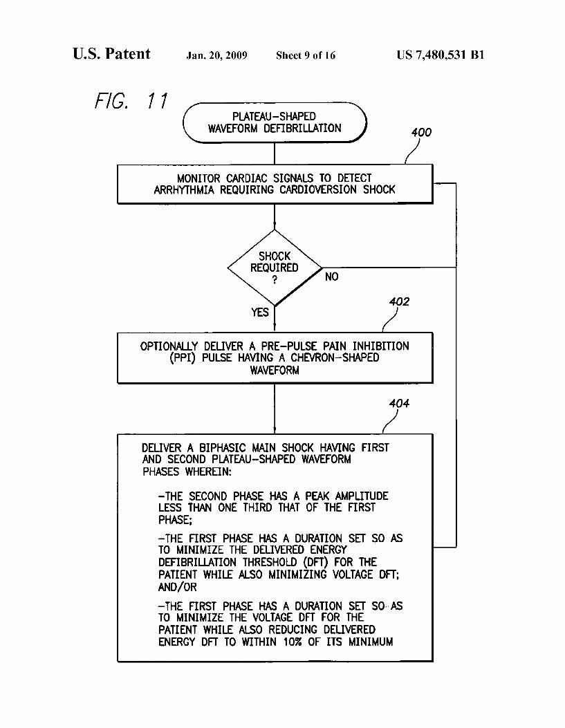
F/G. 77 PLATEAU-SHAPED
WAVEFORM DEFIBRILLATION 400
MONITOR CARDIAC SIGNALS TO DETECT ARRHYTHMIA REQUIRING CARDIOVERSION SHOCK
SHOCK REQUIRED
? NO
402
OPTIONALLY DELIVER A PRE-PULSE PAIN INHIBITION (PPI) PULSE HAVING A CHEVRON-SHAPED
WAVEFORM
404
DELIVER A BIPHASIC MAIN SHOCK HAVING FIRST AND SECOND PLATEAU-SHAPED WAVEFORM PHASES WHEREIN:
—THE SECOND PHASE HAS A PEAK AMPLITUDE LESS THAN ONE THIRD THAT OF THE FIRST PHASE; —THE FIRST PHASE HAs A DURATION sET so AS TO MINIMIZE THE DELIVERED ENERGY DEFIBRIU_ATION THRESHOLD (on) FOR THE PATIENT WHILE ALSO MINIMIZING VOLTAGE DI-T; AND/OR —THE FIRST PHASE HAS A DURATION SET SDI-AS TO MINIMIZE THE VOLTAGE DFT FOR THE PATIENT WHILE ALSO REDUCING DELIVERED ENERGY DFT TO WITHIN 10% OF ITS MINIMUM

US. Patent Jan. 20, 2009
OVERVIEW OF MODIFIED PAIN REDUCTION
TECHNIQUE
Sheet 10 0f 16
MONITOR CARDIAC SIGNALS TO DETECT ARRHYTHMIA REQUIRING
CARDIOVERSION SHOCK
US 7,480,531 B1
SHOCK
REQUgIRED N 0
GENERATE AN ELECTRICAL THERAPEUTIC SHOCK WHEREIN THE SHOCK HAS A VOLTAGE WAVEFORM WITH A REDUCED
LEADING EDGE VOLTAGE FOLLOWED BY A HIGHER PLATEAU
VOLTAGE
APPLY THE SHOCK TO HEART TISSUE OF THE PATIENT
F/G. 72

US. Patent Jan. 20, 2009 Sheet 11 0f 16 US 7,480,531 B1
EXEMPLARY SHOCK 502 GENERATION
C 508 SHARPLY INCREASE THE SHOCK VOLTAGE FROM A BASELINE VOLTAGE TO THE LEADING EDGE VOLTAGE
WHEREIN THE INCREASE IS SUBSTANTIALLY INSTANTANEOUS AND WHEREIN THE LEADING EDGE
VOLTAGE IS 30% TO 70% OF A SUBSEQUENT FIRST PHASE PLATEAU VOLTAGE
(‘514 GRADUALLY INCREASE THE SHOCK VOLTAGE FROM THE
LEADING EDGE VOLTAGE TO THE HIGHER PLATEAU VOLTAGE, WHEREIN THE GRADUAL INCREASE OCCURS
DURING A FIRST EXTENDED INTERVAL OF TIME COMPRISING ABOUT 20% TO 80% OF A TOTAL FIRST
' PHASE DURATION
C“ 520
MAINTAIN THE SHOCK VOLTAGE SUBSTANTIALLY AT THE PLATEAU VOLTAGE FOR A SECOND, EXTENDED INTERVAL
OF TIME COMPRISING THE REMAINING DURATION OF THE FIRST PHASE
C 524
DROP THE SHOCK VOLTAGE BACK TO THE BASELINE VOLTAGE, WHEREIN THE DROP IS SUBSTANTIALLY
INSTANTANEOUS
P76. 73
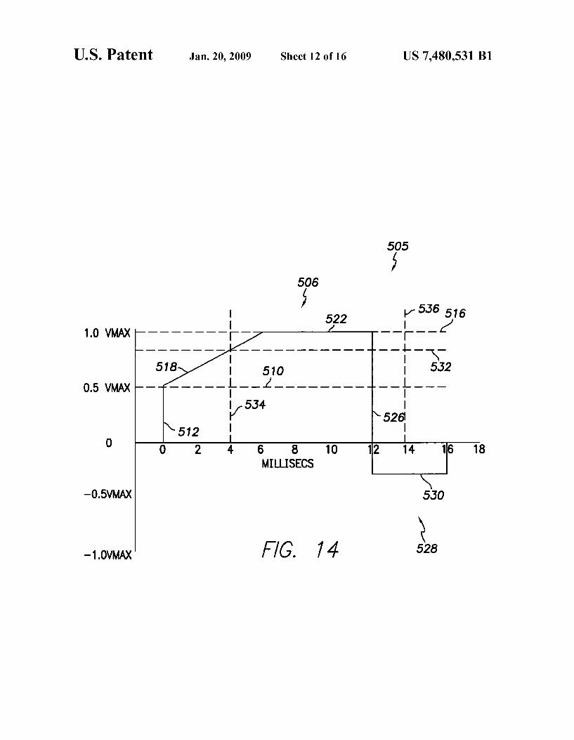
US. Patent Jan. 20, 2009 Sheet 12 0f 16 US 7,480,531 B1
r535 516
18 16 14 10 6 8 MILLISECS
5.30
528 74 F /G.
—0.5VMAX
—1.0VMAX
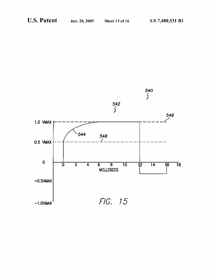
US. Patent Jan. 20, 2009 Sheet 13 0f 16 US 7,480,531 B1
5340 542
548 1.0 VMAX _ _ _ __ _
546 0.5 VMAX ------ - - i ______________ _ _
0 s a 10 112 14 1s 1s MILLISECS
—O.5VMAX
—1.0VMAX

US. Patent Jan. 20, 2009 Sheet 14 0f 16 US 7,480,531 B1
550
552
1.0 VMAX
0.5 VMAX
MILLISECS
—O.5VMAX
—1.0VMAX F/G. 76

US. Patent Jan. 20, 2009 Sheet 15 0f 16 US 7,480,531 B1
560
1.0 VMAX
0.5 VMAX
6 8 10 12 14 16 18 MILLISECS
—O.5VMAX
—1.0VMAX 77

US. Patent Jan. 20, 2009 Sheet 16 0f 16 US 7,480,531 B1
m: 6E 1|l. m2:
\\ 2 En mummiovlq
?n 85:52 )J
v.85 22: M92 E
on 2: HSVJJOA

US 7,480,531 B1 1
SYSTEM AND METHOD FOR REDUCING PAIN ASSOCIATED WITH CARDIOVERSION SHOCKS GENERATED BY IMPLANTABLE
CARDIAC STIMULATION DEVICES
RELATED APPLICATION DATA
This application is a continuation-in-part (CIP) of copend ing US. patent application Ser. No. 11/005,976, ?led Dec. 6, 2004, entitled “System and Method for Reducing Pain Asso ciated With Cardioversion Shocks Generated By Implantable Cardiac Stimulation Devices By Using Plateau-Shaped Waveforms”, Which Was a continuation-in-part (CIP) of US. patent application Ser. No. 10/855,654, ?led May 26, 2004, entitled “System and Method for Reducing Pain Associated With Cardioversion Shocks Generated By Implantable Car diac Stimulation Devices”, now US. Pat. No. 7,155,286, Which is related to US. patent application Ser. No. 10/855, 840, ?led May 26, 2004, entitled “System and Method for Reducing Pain Associated With Cardioversion Shocks Gen erated by Implantable Cardiac Stimulation Devices”, now US. Pat. No. 7,231,255.
FIELD OF THE INVENTION
The invention generally relates to implantable cardiac stimulation devices such implantable cardioverter/de?brilla tors (ICDs) and, in particular, to techniques for generating cardioversion shocks modi?ed to reduce pain associated With the shock.
BACKGROUND OF THE INVENTION
Atrial ?brillation (“AF”) is a cardiac arrhythmia Wherein the atria beat chaotically, thereby providing generally poor conduction of blood into the ventricles of the heart and hence reducing the How of blood throughout the body. AP has been shoWn to lead to long-term health problems such as increased risk of thrombolytic stroke. AF can also cause reduced car diac e?iciency, irregular ventricular rhythm and unpleasant symptoms such as palpitations and shortness of breath. In some cases, AF can trigger ventricular ?brillation (V F) Wherein the ventricles of the heart beat chaotically thereby providing little or no blood How to the brain and other organs. VF, if not terminated, is usually fatal.
Hence, it is highly desirable to terminate AF should it arise and revert the atria to a normal rhythm. The current, most common therapy for atrial ?brillation is the administration of anti-arrhythmic drugs that control atrial and ventricular rates during AF. HoWever, these drugs can actually be proarrhyth mic, causing the arrhythmia to Worsen. At best, anti-arrhyth mic drugs appear to provide short-term therapy. Another tech nique for terminating AF is to administer an electrical cardioversion shock to the atria of the heart. The cardiover sion shock, if successful, terminates the chaotic pulsing of the atria and causes the atria to resume a normal beating pattern. Patients prone to AP may have an ICD implanted therein capable of detecting AF and automatically administering one or more cardioversion shocks to terminate AF. Typically, about tWo joules of energy is administered Within each car dioversion shock at an initial voltage of betWeen 100 to 500 volts (V). The duration of the pulse is usually betWeen 5-15 milliseconds (ms) and is a descending voltage capacitive discharge Waveform. State of the art ICDs are also capable of detecting a Wide variety of other heart arrhythmias, such as VP, and for administering appropriate therapy as Well. For VF, the ICD administers a much stronger cardioversion shock
20
25
30
35
40
45
50
55
60
65
2 (referred to as a de?brillation shock) directly to the ventricles of the heart. The de?brillation shock typically has at least ten to tWelve joules of electrical energy. Note that, herein, “car dioversion” generally refers to the delivery of any electrical shock intended to synchroniZe action potentials of myocar dial cells Within the heart to terminate arrhythmias. De?bril lation, herein, refers to a type of cardioversion speci?cally intended to terminate ?brillation.
Although atrial cardioversion shocks have been found to be effective for terminating AF Within many patients, the shocks can be quite painful. One reason is that the patient is typically conscious and alert at the time the shock is administered. In contrast, the much stronger ventricular de?brillation shocks for terminating VF are typically not administered until the patient has lost consciousness and hence the patient may feel only residual chest pain upon being revived. Because AF is not usually immediately life-threatening, painful cardiover sion shocks for its treatment are often perceived by patients as being Worse than the condition itself and therefore not toler ated. Indeed, anxiety arising from the fear of receiving a painful cardioversion shock may be suf?cient to raise the heart rate suf?ciently to trigger the shock. As some patients have hundreds of AF episodes per year, techniques for reduc ing the pain associated With cardioversion shocks are highly desirable. It is also desirable to reduce pain associated With ventricular de?brillation shocks. Although patients receiving ventricular de?brillation shocks are usually unconscious When the shock is delivered, in some cases, such shocks are erroneously delivered While the patient is conscious due to false-positive VF detection, resulting in considerable patient pain. One method for reducing pain arising from cardioversion
shocks involves altering the stimulation Waveform of the shock to, for example, reduce or smooth initial voltage peaks. See, for example, US. Pat. No. 5,830,236, to MouchaWar et al., entitled “System for Delivering LoW Pain Therapeutic Electrical Waveforms to the Heart” and US. Pat. No. 5,906, 633, also to MouchaWar et al., entitled “System for Delivering Rounded LoW Pain Therapeutic Electrical Waveforms to the Heart.” Shock smoothing is illustrated by Way of FIGS. 1 and 2. FIG. 1 illustrates a conventional cardioversion shock Wave form 1 (shoWn in V) along With a resulting cardiac membrane response 2. Herein, the cardiac membrane response is shoWn in arbitrary response units for the purposes of comparison. The shock Waveform is biphasic, With a peak voltage of the initial (positive) phase at about 100 V and With a peak voltage of the second (negative) phase at about 33 V. The peak of the resulting cardiac membrane response occurs at about 4 ms and is at about 50 response units. Peak voltage of the initial phase is typically regarded as the primary determinant of shock pain; Whereas the peak cardiac membrane response is typically regarded as the primary indicator of shock effective ness. Hence, With the conventional shock Waveform of FIG. 1, the effectiveness of the shock is only about 50 cardiac response units; the resulting pain is associated With 100 V.
FIG. 2, in contrast, illustrates a smoothed cardioversion Waveform 3 along With a resulting cardiac membrane response 4, shoWn in the same arbitrary response units of FIG. 1 for comparison purposes. The shock Waveform of FIG. 2 is smoothed so as to reduce the peak voltage of the initial phase to about 70V. The peak voltage of the second (negative) phase remains at about 33 V. The peak of the resulting cardiac membrane response is still about 45 response units. Hence, With the smoothed shock Waveform of FIG. 2, the cardiover sion shock is almost as effective as With the non-smoothed Waveform of FIG. 1; Whereas the resulting pain is signi?

US 7,480,531 B1 3
cantly lower, ie the resulting pain is associated With a peak voltage of only about 70 V rather than With a peak voltage of 100 V. One Way to generate the smoothed Waveform of FIG. 2 is to
start With a higher initial capacitor voltage (about 160 V) than the non-smoothed Waveform of FIG. 1 and then use resistive loss to loWer the voltage as needed. The capacitor voltage is shoWn by Way of phantom line 5, Which decreases exponen tially. The capacitor voltage at each point in time must be at least as great as the output pulse being generated at that same point in time. During times When the capacitor voltage is greater than the corresponding output shock voltage, the addi tional energy is dissipated as heat. Thus, pain reduction is achieved at the expense of consuming someWhat greater energy per shock.
Note that the shock Waveforms of FIGS. 1 and 2 both provide a fairly substantial peak voltage for the second (nega tive) phase as compared to that of the initial phase. For the non-smoothed Waveform of FIG. 1, the peak voltage of the second phase is at least about one third that of the initial phase. For the smoothed Waveform of FIG. 2, the peak voltage of the second phase is at least about four tenths that of the initial phase. Conventionally, it is believed that the second phase must have a fairly large peak voltage is comparison With that of the initial phase to achieve a suitable de?brillation threshold. In addition, conventionally, it is believed that long duration shock phases are disadvantageous. For example, in the case of FIG. 1, the peak cardiac membrane response is achieved at about 4 ms, although the voltage remains rela tively high until the 6 ms point, at Which it is ?nally truncated. Truncation of the ?rst phase of a conventional shock Wave form is performed, in large part, to reduce the amount of shock energy delivered after the peak membrane response. In this regard, the smoothed Waveform of FIG. 2 has the advan tage of achieving peak membrane response just at the end of the initial phase With the voltage of the initial (positive) phase then decreasing promptly before commencement of the sec ond (negative) phase.
Note also that the graphs of FIGS. 1 and 2, and all other graphs provided herein, include styliZed representations of the parameters being illustrated. This is done so as to more clearly illustrate pertinent features of those parameters. The graphs should not be construed as illustrating actual clini cally-detected parameters.
Thus, smoothed Waveforms of the type shoWn in FIG. 2 can be effective in reducing the resulting pain. It Would be desir able, hoWever, to achieve an even greater amount of pain reduction Without reducing shock effectiveness. It is to that end that certain aspects of the invention are directed. More over, it Would also be desirable to provide a relatively simple circuit capable of generating improved shock Waveforms and other aspects of the invention are directed to that end.
Another method for reducing pain arising from cardiover sion shocks is to deliver a pre-pulse pain inhibition (PPI) pulse prior to the main shock. See, for example, US. Pat. No. 6,091,989 to SWerdloW et al., entitled “Method and Appara tus for Reduction of Pain from Electric Shock Therapies.” With PPI techniques, a relatively Weak stimulus (the PPI pulse) is applied to the patient shortly before a main cardio version shock. The human pain perception system responds to the Weak stimulus in such manner that the pain associated With the subsequent main cardioversion shock is reduced or otherWise inhibited. PPI techniques typically employ either a single relatively long, loW-voltage PPI pulse or a single rela tively short, high-voltage PPI pulse. The long, loW-voltage PPI pulse is usually delivered at about 12-20 V. The shorter, high-voltage PPI pulse is usually delivered at the voltage of
20
25
30
35
40
45
50
55
60
65
4 the subsequent main cardioversion shock. Each has its respective advantages and disadvantages.
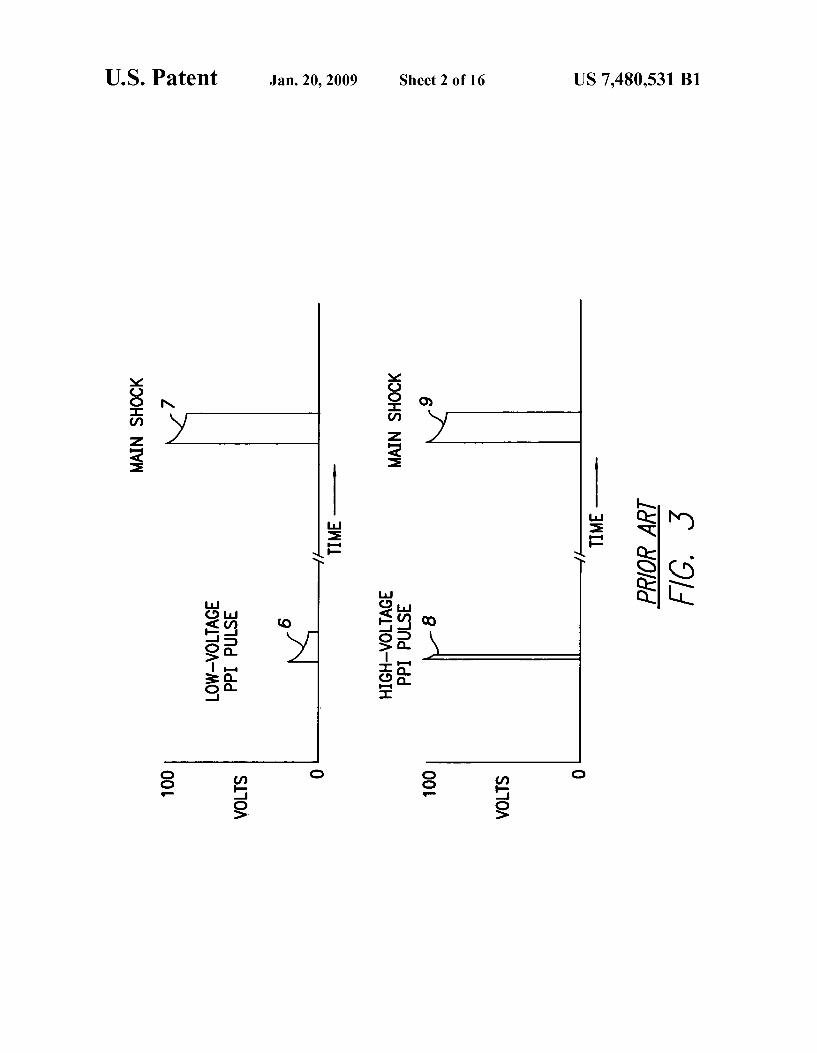
Conventional loW-voltage and high-voltage PPI pulses are illustrated by Way of the timing diagrams of FIG. 3, Which shoW a loW-voltage PPI pulse 6 folloWed by a high-voltage main cardioversion shock 7 and Which also shoW a much shorter high-voltage PPI pulse 8 folloWed also by a main shock 9. All Waveforms of FIG. 3 are monophasic, though biphasic Waveforms may instead be employed. None of the Waveforms has been smoothed. The exemplary loW-voltage PPI pulse and its subsequent main shock are of substantially equal duration (typically about 1-10 ms) but the PPI pulse has an initial peak voltage of only about 20 V Whereas the main shock has an initial peak voltage of about 100 V. The exem plary high-voltage PPI pulse is much shorter than its subse quent main shock (e.g., as short as 0.1 ms as opposed to 1-10 ms) but is of equal voltage (again about 100 V). In each case, the PPI pulse is provided to reduce the pain perceived by the patient during the subsequent main cardioversion shock. The time scale of FIG. 3 is arbitrary but, typically, PPI pulses are delivered 30-500 ms prior to the main cardioversion shock. A signi?cant advantage of generating a short, high-voltage
PPI pulse at the same voltage as the main shock is that only a single shocking capacitor is required, precharged to the main shock voltage. To instead deliver a PPI pulse at a loW-voltage folloWed by a main shock at a much higher voltage, tWo shocking capacitors are usually requiredione precharged to the loW-voltage and the other precharged to the high-voltage. HoWever, high-voltage PPI pulses can be painful in and of themselves thus reducing their effectiveness in overall pain reduction. Hence, loW-voltage PPI pulses are typically pre ferred despite the need for an extra shocking capacitor. In this regard, note that capacitors used for generating conventional pacing pulses ordinarily cannot be employed to also generate loW-voltage PPI pulses, Which typically require a someWhat higher voltage than the pacing pulses. One technique for delivering high-voltage PPI pulses that
are not painful in and of themselves is to utiliZe extremely short duration “sliver” pulses, Which are typically only about 25-50 microseconds (Us) in duration. The sliver pulses are nevertheless suf?cient to provide pain inhibition. Preferably, the high-voltage PPI sliver pulses are delivered betWeen elec trodes implanted Within the heart, such as betWeen a right ventricular (RV) coil and a superior vena cava (SVC) coil, so that high-voltage can be used Without risk of signi?cant pain arising from the PPI pulse itself. In particular, pain is reduced by generating the PPI pulse aWay from the device can or housing. Pulses instead generated using the device can as a return electrode may stimulate sensitive skin nerves and sen sitive alpha motor neurons in the pectorals. The subsequent main cardioversion shock is preferably delivered using Widely spaced electrodes, such as betWeen the SVC coil and the housing of the implanted device, to ensure maximum likelihood of success. Sliver pulses are discussed in US. patent application Ser. No. 10/428,222 of Kroll et al., entitled “System and Method for Generating Pain Inhibition Pulses Using an Implantable Cardiac Stimulation Device”, ?ledApr. 30, 2003, Which is incorporated by reference herein.
Still further improvements Were set forth in US. patent application Ser. Nos. 10/855,654 and 11/005,976, cited above. These improvements, Which are also described herein beloW, pertain to the use of relatively loW-voltage PPI pulses With chevron-shaped Waveforms and relatively high-voltage main shocks having plateau-shaped Waveforms. By employ ing plateau-shaped Waveforms for the main shocks, a greater cardiac membrane response can be achieved at an equivalent peak voltage as compared to conventional shock Waveforms.