1,2, shahin mansor1, m.r.m akramin3 and akhtar razul razali
TRANSCRIPT
Journal of Mechanical Engineering and Sciences
ISSN (Print): 2289-4659; e-ISSN: 2231-8380
Volume 13, Issue 1, pp. 4704-4717, March 2019
© Universiti Malaysia Pahang, Malaysia
DOI: https://doi.org/10.15282/jmes.13.1.2019.25.0395
4704
Design and parametric characterization of flexure bearing as automotive valve spring
replacement
M. Razali Hanipah1,2, Shahin Mansor1, M.R.M Akramin3 and Akhtar Razul Razali1,4
1Automotive Engineering Research Group (AERG), Faculty of Mechanical Engineering,
Universiti Malaysia Pahang, 26600 Pekan, Pahang, Malaysia *Email: [email protected]
2Automotive Engineering Centre (AEC), Universiti Malaysia Pahang,
26600 Pekan, Pahang, Malaysia 3Structural Materials and Degradation Group (SMDG),
Faculty of Mechanical Engineering, Universiti Malaysia Pahang, 4Manufacturing Focus Group (MFG), Faculty of Mechanical Engineering,
Universiti Malaysia Pahang,
ABSTRACT
Automotive valve springs occupy substantial space in the cylinder head of an internal
combustion engine and contribute to frictional loss. In this paper, the design and analyses of
a flat spring concept, known as flexure bearing are presented. Flexure bearing act like a
typical spring which support the shaft but only allow axial displacement, thus reduce the
friction of the system. The objective of the research is to design and conduct parametric
characterization of flexure bearing for valve spring replacement in a small internal
combustion engine. The analyses of flexure bearing strength for different designs, materials
and thicknesses were conducted using finite element method. The results show that the
maximum stress values are less affected by the material type compared to the number of arms
despite a significant difference in young modulus values. The strain values are limited to less
than 1% for all materials when the thickness is more than 1mm. The results have provided
characteristics for future selection of the flexure bearing in relation to the intended axial
displacement.
Keywords: Flexure Bearing; Finite Element; Design
INTRODUCTION
A recent successful trend in passenger vehicles improvement involved fuel economy
improvement through start-stop technology [1, 2]. An aggressive approach to reduce fuel
consumptions is by improving internal combustion engine efficiency. Valvetrain components
design are essential towards an efficient internal combustion engine. One of the component
is valve springs, whose stiffness, dimensions and mass are critical for engine operation [3,
4]. In addition, poorly designed valve springs could cause abnormal vibration and hence,
noise [5]. Flexure bearing is metal disc with slots cutting that permit flexing in the axial
direction while ensuring a higher radial stiffness. Mostly, flexure bearing is used to support
brought to you by COREView metadata, citation and similar papers at core.ac.uk
provided by UMP Institutional Repository
Razali et. al / Journal of Mechanical Engineering and Sciences 13(1) 2019 4704-4717
4705
shafts that perform a purely linear motion and are commonly used in free piston Stirling
machine incorporated with a linear motor [6]. Gaunekar, Göddenhenrich [7] presented non-
dimensional design curves for a flexure disc with spiral arm configuration for a certain range
of sizes and strokes obtained from finite element analysis and validated through experimental
measurements. Chen, Chen [8] had presented a spiral profile design procedures and
parameter analyses through finite element analyses. Lee and Pan [9] had presented flexure
bearing analysis procedures and design charts. According to the design charts developed for
the spiral flexure, material fatigue stress allowable and the flexure stiffness requirement were
chosen as a preferred design configuration [9]. Simcock [10] had presented investigation of
materials for long life, high reliability flexure bearing springs for Stirling cryocooler
applications. Kavade and Patil [6] had investigated the flexure bearing in linear compressor
by varying the spiral angle with result through finite element method. Jomde, Anderson [11]
had conducted parametric investigation on flexure bearing to enhance its performance and
service life. Thombare and Dhande [12] conducted parametric modelling and FEA analyses
for flexural bearings with different spiral profiles but limited to 1 mm thickness.
In this paper, the design characteristics of flexure bearing for replacing an existing
single cylinder engine valve spring are investigated through finite element analyses. It covers
different types of materials, designs and thicknesses.
METHODOLOGY
Geometric Characteristic
Geometrical characteristic is one of the most importance design characteristics of a flexure
bearing as it can influence the performance and frequency. The typical design is a circular
plate with three Archimedes spiral slits [13], this slit is known as involute and mathematically
presented in details by Chen, Chen [8].
A variation of geometry parameters should be considered when designing a flexure
spring; such as the thickness of the disk, the number of arms, the turn angle, the diameter of
starting and ending hole, the slot width, arm width and a fixed radius at the beginning of the
spiral [8].
Each spiral slot is made of locus of points corresponding to the location over time of
a point moving away from a fix centre point with a constant speed along a line which rotates
with constant angular velocity. Equivalently, in polar coordinates (r, θ) the equation can
describe as
𝑟 = 𝑎 + 𝑏𝜃 (1)
with real numbers a and b. Changing the parameter a will turn the spiral, while b controls the
distance between successive turnings. The parametric Cartesian equation in Cartesian
coordinate is defined respectively as:
𝑥 = 𝑐𝑜𝑠(𝜃) + 𝜃 𝑠𝑖𝑛(𝜃) (2)
𝑦 = 𝑠𝑖𝑛(𝜃) − 𝜃 𝑐𝑜𝑠(𝜃) (3)

Design and parametric characterization of flexure bearing as automotive valve spring replacement
4706
Figure 1 shows the geometric representation of involute in two-slot design developed in
computer aided design (CAD) tool.
Figure 1. Geometrical description of involute
Target Specifications
The replacement spring is for a small internal combustion engine with 65cc cylinder capacity,
four-stroke cycle run on gasoline [14]. It is chosen due to its small and compact size, simple
design, air-cooled, mass-produced and availability of spare parts. Further, it runs on a four-
stroke cycle engine utilising two-stroke lubrication and intake crankcase compression. Table
1 shows the engine specifications as obtained from the manufacturer datasheet and from
measurement in the lab setup as outlined in [15].
Table 1. The engine specifications.
Parameter Value
Capacity [cm3] 65
Bore [mm] 50
Stroke [mm] 33
Geometric compression ratio [-] 9.5:1
Valve lift [mm] 4.0
Intake valve diameter [mm] 20
Exhaust valve diameter [mm] 18
Razali et. al / Journal of Mechanical Engineering and Sciences 13(1) 2019 4704-4717
4707
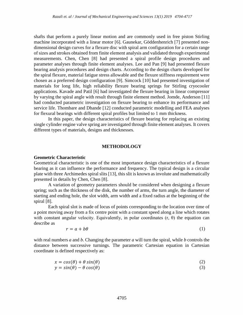
Figure 2 shows the current valve spring configuration of the engine where a set of spring
retainer plate holds each helical spring in pre-compression state to keep both valves closed.
The opening and closing of the valve during engine cycle is done through cam actuated
mechanism which is beyond the scope of this paper.
Figure 2. The current valve-spring configuration on the engine.
Design and Finite Element Analyses Upon employing the design procedures for flexure bearing, several conceptual designs are
constructed using three-dimensional computer aided design (CAD) tool.
There are three concepts of created in 3D CAD for the project as shown in Figure 3.
The concept selection process depends on the several aspects evaluated through a design
matrix. Among important design aspects are the material characteristics and design strength.
The third concept has been chosen based on its simplicity, low cost of manufacturing with
potentially lowest mechanical stress as reported by Jomde, Anderson [11] and Kharadi,
Jadhav [16].

Design and parametric characterization of flexure bearing as automotive valve spring replacement
4708
Figure 3. Three flexure bearing concept designs developed in 3D CAD.
Further analyses of the flexure bearing strength and elasticity was conducted using
SolidWorks Simulation under mechanical testing. The simulation tool is general purpose
finite element analysis which is reliable for linear elastic analysis [17].
This study focus on three major aspects of analysing the flexure bearing design which
are the thickness, number of arm and material type. These parameters are important for better
understanding of the flexure bearing characteristics for replacing the conventional valve
spring. Next, the material of the design is selected. Choosing different material will affect
greatly on the result of analysis due to material properties. Steel alloy is first selected for the
flexure bearing. Other materials chosen includes stainless steel, beryllium copper alloy and
titanium alloy based on previous research [18].
Figure 4 summarised the FEA procedures in SolidWorks simulation. First the design
is fixed, then it is loaded with 20 N force which is similar to the maximum force generated
on the helical spring of current engine at maximum lift. Finally, meshing is applied with
appropriately chosen number of nodes and mesh size.

Razali et. al / Journal of Mechanical Engineering and Sciences 13(1) 2019 4704-4717
4709
Figure 4. The fixture, load settings and meshing for the finite element analyses in
SolidWorks.
Table 2 shows the governing design parameters for the parametric design simulation. The
number of arms, thickness and material have been identified as the main parameters affecting
the design of the flexure bearing.
Table 2. The details of design parameters for flexure bearing simulation.
Parameters Value / Input
Number of arms
2
3
4
5
Thickness [mm]
0.5
1.0
1.5
2.0
Material
Ti-6
BeCu C13700
Alloy Steel AISI 4160
AISI 316

Design and parametric characterization of flexure bearing as automotive valve spring replacement
4710
RESULTS AND DISCUSSIONS
The static analyses focused on axial displacement, stress analyses and strain analyses. From
these analyses, different parameters such as thickness, type of material and number of arms
were analysed using FEA method under SolidWork simulation.
Axial Displacement
Figure 5 illustrate the FEA model axial displacement, in this case it shows the maximum
displacement of the centre up to 20 mm under the 20 N load.
Figure 5. Deformation of flexure bearing model.
By changing the design parameters and materials, subsequent models were analysed. Figure
6 shows flexure bearing for steel alloy where the axial displacement rose steeply when the
number of arms is more than 3 while the thickness is 0.5 mm. A steady rise can be observed
for other thicknesses.

Razali et. al / Journal of Mechanical Engineering and Sciences 13(1) 2019 4704-4717
4711
Figure 6. The maximum axial displacement at 20 N for various thicknesses and arm
quantity of steel alloy.
Different trend is observed in stainless steel, beryllium copper and titanium alloy as shown
in Figure 7 until Figure 9. Apparently in all these materials, the flexure bearing becomes
rigid when the number of arm is more than 4.
Figure 7. The maximum axial displacement at 20 N for various thicknesses and arm
quantity of stainless steel (316 SS).

Design and parametric characterization of flexure bearing as automotive valve spring replacement
4712
Figure 8. The maximum axial displacement at 20 N for various thicknesses and arm
quantity of beryllium copper (BeCu) alloy.
Figure 9. The maximum axial displacement at 20 N for various thicknesses and arm
quantity of titanium alloy.
Based on these different materials modelled, the results show higher axial displacement for
titanium alloy compared to other material. This is related to modulus of elasticity of the
material. Titanium has the highest axial displacement due to lowest value of elastic modulus
at 115MPa compared to steel alloy at 210MPa.

Razali et. al / Journal of Mechanical Engineering and Sciences 13(1) 2019 4704-4717
4713
In terms of the number of arms, the results show that by increasing the number of arms
resulted in higher axial displacement due to lower axial stiffness [6]. However, this research
has found that at 5-arm design, the axial displacement obtained shows a decline. Figure 10
illustrates the impact of number of arms with axial displacement values.
Figure 10. Axial displacement vs. number of arms of different materials for 0.5 mm
thickness of flexure bearing.
Stress Analysis
Figure 11 shows the distribution of equivalent stress of flexure bearing for 4-arm design when
the 20N load was exerted on the centre part.
Figure 11. Stress analysis of flexure bearing model.

Design and parametric characterization of flexure bearing as automotive valve spring replacement
4714
The results obtained from the simulation shows that most of the maximum stress occurred at
the end of the involute as shown in Figure 12 and the lowest at the fixture points. This
maximum stress can be reduced as proposed by Meymian, Clark [19], up to 20% of stress
reduction can be achieved when applying a semi-circle end profile on end point of spiral [19].
Figure 12. Maximum stress concentration
Figure 13 shows the stress versus number of arms for different materials at 0.5 mm thickness
of flexure bearing design. It shows that the value of stress increasing when the number of
arm increase. Further, at 4 and 5 arms design; the maximum stress is almost similar for all
materials. Based on the result obtained, five-arm flexure produces the highest value of von
Mises stress with titanium alloy produce 4.2 GN/m².
Figure 13. Stress vs. number of arms in different materials for 0.5 mm thickness of flexure
bearing.

Razali et. al / Journal of Mechanical Engineering and Sciences 13(1) 2019 4704-4717
4715
Strain Analyses
Figure 14 shows the strain contour of 4-arm flexure bearing under the same loading which
correlates to the stress contour shown in Figure 11.
Figure 14. Strain analysis of flexure bearing model.
Figure 15 shows the maximum strain values of 4-arm design in different materials. The
highest strain was produced in 0.5 mm thickness design for the titanium alloy with a value
of 7.24E-03 mm/mm. The strain decreases along with the thickness of flexure bearing.
Figure 15. Strain vs. thickness in different material of 4 arms flexure.

Design and parametric characterization of flexure bearing as automotive valve spring replacement
4716
CONCLUSIONS
In this investigation, the aim was to design and conduct parametric characterization of flexure
bearing. Three concept designs were developed, and a final single piece design was selected
due to its simple and cost-effective design.
This single piece design has undergone parametric investigations using finite element
method in three-dimensional model. The effect of different thicknesses, types of materials
and number of arms were studied.
It is found that, Titanium alloy produced the highest axial displacement at 23mm
when subjected to the same load value as compared to other materials tested. This has
resulted in the highest maximum stress for Titanium alloy at 4.2 GN/m². However, the
maximum stresses in all materials approaches similar values when the number of arm is more
than three up until five arms (which is the maximum quantity in the design). Finally, the
strain values for all materials are less than 1% when the thickness is above 1mm.
ACKNOWLEDGEMENTS
The authors would like to thank the Ministry of Energy, Science, Technology, Environment
and Climate Change (MESTECC) for the financial grant (project no. 03-01-16-SF0172) and
also Universiti Malaysia Pahang (www.ump.edu.my) for providing laboratory facilities.
REFERENCES
[1] Abas MA, Wan Salim WS, Ismail MI, Rajoo S, Martinez-Botas R. Fuel consumption
evaluation of SI engine using start-stop technology. Journal of Mechanical
Engineering and Sciences 2017;11:2967-78.
[2] Salim WSIW, Mahdi AAM, Ismail MI, Abas MA, Martinez-Botas RF, Rajoo S.
Benefits of spark-ignition engine fuel-saving technologies under transient part load
operations. Journal of Mechanical Engineering and Sciences 2017;11:3027-37.
[3] Siczek K, Siczek K. Studies on the dynamics the valve train with machined valve
springs. Combustion Engines 2017;1.
[4] Gowtham R, Sangeetha N. Design and analysis of exhaust valve springs in IC
engines. International Journal of Innovative Research in Science, Engineering and
Technology 2017.
[5] Zheng H, Yan F, Lu C, Xu F, Li Q, Tian W. Optimization design of the valve spring
for abnormal noise control in a single-cylinder gasoline engine. Proceedings of the
Institution of Mechanical Engineers, Part D: Journal of Automobile Engineering
2017;231:204-13.
[6] Kavade MV, Patil CB. Optimization of Flexure Bearing Using FEA for Linear
Compressor. International Journal of Engineering and Science 2012.
[7] Gaunekar AS, Göddenhenrich T, Heiden C. Finite element analysis and testing of
flexure bearing elements. Cryogenics 1996;36:359-64.
[8] Chen N, Chen X, Wu YN, Yang CG, Xu L. Spiral profile design and parameter
analysis of flexure spring. Cryogenics 2006;46:409-19.

Razali et. al / Journal of Mechanical Engineering and Sciences 13(1) 2019 4704-4717
4717
[9] Lee CC, Pan RB. Flexure Bearing Analysis Procedures and Design Charts. In: R.G.
R, editor. Cryocoolers 9. Boston, MA: Springer; 1997.
[10] Simcock CJ. Investigation of Materials for Long Life, High Reliability Flexure
Bearing Springs for Stirling Cryocooler Applications. In: International Cryocooler
Conference, 2007.
[11] Jomde A, Anderson A, Bhojwani V, Kharadi F, Deshmukh S. Parametric Analysis
Of Flexure Bearing For Linear Compressor. Materials Today: Proceedings
2017;4:2478-86.
[12] Thombare AT, Dhande DY. Modeling and FEA analysis of Flexural Bearing for
Different Profiles. International Journal of Engineering Trends and Technology
2015;20:175-8.
[13] Al-Otaibi ZS, Jack AG. Spiral flexure springs in single phase linear-resonant motors.
In: 42nd International Universities Power Engineering Conference, Brighton, UK, 4-
6 September, 2007.
[14] Andreas Stihl AG. 4-MIX engine: Lightweight and with good lugging power.
Retrieved from http://www.stihl.com/4-mix-engine-lightweight-and-with-good-
lugging-power.aspx; 17 November 2014.
[15] Zahidi MK, Hanipah MR, Ramasamy D, Noor MM, Kadirgama K, Rahman MM.
The two-stroke poppet valve engine. Part 1: Intake and exhaust ports flow
experimental assessments. IOP Conference Series: Materials Science and
Engineering 2017;257:012023.
[16] Kharadi FH, Jadhav MS, Kanhurkar SD, Pereira PA, Bhojwani VK, Phadkule S.
Selection Of High Performing Geometry In Flexure Bearings For Linear Compressor
Applications Using FEA. International Journal of Scientific & Technology Research.
2015.
[17] Boyles C. Solid Solution: So how accurate is SOLIDWORKS Simulation? .
Retrieved from https://www.solidsolutions.co.uk/blog/2017/09/so-how-accurate-is-
SOLIDWORKS-simulation/; 21 April 2018.
[18] Amoedo S, Thebaud E, Gschwendtner M, White D. Novel parameter-based flexure
bearing design method. Cryogenics 2016;76:1-9.
[19] Meymian NZ, Clark NN, Musho T, Darzi M, Johnson D, Famouri P. An optimization
method for flexural bearing design for high-stroke high-frequency applications.
Cryogenics 2018;95:82-94.