11eer qa series q-tectm air conditioner
TRANSCRIPT

1 1 E E R W A S E R I E S W A L L - M O U N T T M P A G E 1 O F 2 7 FO R M N O. S3573 -1118 • S U P E R S E D E S N E W
1.5 to 3 Ton 208V to 460V 60hz Air Conditioner Speci�cations
11EER WA Series WALL-MOUNT™ 1.5 to 3 Ton208V to 460V 60hz Air Conditioner Specifications.
The Bard Wall-Mount Air Conditioner is a selfcontained energy efficient system, which is designedto offer maximum indoor comfort at a minimal costwithout using valuable indoor floor space or outsideground space. This unitis the ideal productforversatile applications such as: new construction,modular offices, school modernization,telecommunication structures, portable structures orcorrectional facilities. Factory or field installedaccessories are available to meet specific jobrequirements for your unique application.
W36AB-A Wall-Mount™
11EER WA Series WALL-MOUNT™ 1.5 to 3 Ton208V to 460V 60hz Air Conditioner Specifications.
The Bard Wall-Mount Air Conditioner is a selfcontained energy efficient system, which is designedto offer maximum indoor comfort at a minimal costwithout using valuable indoor floor space or outsideground space. This unitis the ideal productforversatile applications such as: new construction,
offices, school modernization,telecommunication structures, portable structures orcorrectional facilities. Factory or field installedaccessories are available to meet specific jobrequirements for your unique application.
W36AB-A Wall-Mount™
Climate Control Solutions
BARDHVAC.COM
FO R M N O. S362 0 - 0122
11EER QA Series 3 to 3.5 Ton Q36A thru Q48A Indoor Air Conditioner Specifications
The Q-TEC Series self contained packaged air conditioner is designed to be installed inside a building structure against an exterior exposed wall. Q-TEC’s design provides “whisper” quiet operation with total comfort for the occupants. This design eliminates the need for roof-mounted equipment and outside condensing units and can meet your specific architectural requirements.
Q-TEC’s “quiet technology” provides extremely low sound levels (both indoor and outdoor) by using special components and materials in the construction of the unit. By using special motors, sound insulation and other sound absorbing construction, we have built a heat pump system that is significantly quieter than the typical indoor product available today.
Q-TEC is designed for both new construction and renovation projects for schools, modular buildings and light commercial buildings. A variety of ventilation and dehumidification options are designed to address your projects’ indoor air quality and dehumidification requirements.
11EER QA Series Q-TECTM Air Conditioner
• Complies with efficiency requirements of ASHRAE/IESNA 90.1-2016
• Certified to ASNI/ARI Standard 390-2003 for SPVU (Single Package Vertical Units)
• Intertek ETL Listed to Standard for Safety Heating and Cooling Equipment ANSI/UL 1995/CSA 22.2 No. 236-05 Fourth Edition
• Commercial Product - Not intended for residential application
• Bard is an ISO 9001:2015 Certified Manufacturer• The AHRI Certified® mark indicates Bard
Manufacturing Company’s participation in the AHRI Certification program. For verification of individual certified products, go to www.ahridirectory.org.
Q A S E R I E S I N D O O R W A L L - M O U N T T M P A G E 2 O F 2 5 FO R M N O. S362 0 - 0122 • S U P E R S E D E S 1021
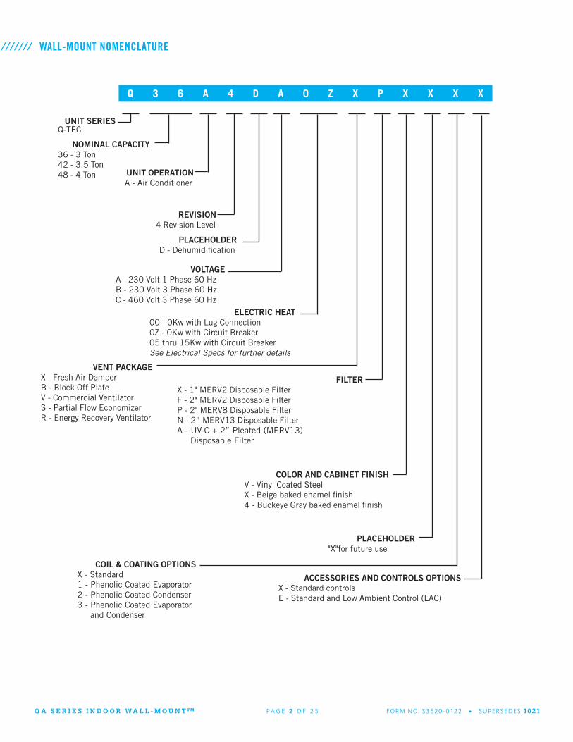
WALL-MOUNT NOMENCLATURE
Q 3 6 A 4 D A 0 Z X P X X X X
NOMINAL CAPACITY36 - 3 Ton42 - 3.5 Ton48 - 4 Ton
UNIT SERIESQ-TEC
REVISION4 Revision Level
PLACEHOLDERD - Dehumidification
UNIT OPERATIONA - Air Conditioner
VOLTAGEA - 230 Volt 1 Phase 60 HzB - 230 Volt 3 Phase 60 HzC - 460 Volt 3 Phase 60 Hz
ELECTRIC HEAT00 - 0Kw with Lug Connection0Z - 0Kw with Circuit Breaker05 thru 15Kw with Circuit BreakerSee Electrical Specs for further details
FILTERX - 1" MERV2 Disposable FilterF - 2" MERV2 Disposable FilterP - 2" MERV8 Disposable FilterN - 2” MERV13 Disposable FilterA - UV-C + 2” Pleated (MERV13) Disposable Filter
COLOR AND CABINET FINISHV - Vinyl Coated SteelX - Beige baked enamel finish4 - Buckeye Gray baked enamel finish
ACCESSORIES AND CONTROLS OPTIONSX - Standard controlsE - Standard and Low Ambient Control (LAC)
PLACEHOLDER"X"for future use
COIL & COATING OPTIONS X - Standard 1 - Phenolic Coated Evaporator 2 - Phenolic Coated Condenser 3 - Phenolic Coated Evaporator and Condenser
///////
VENT PACKAGEX - Fresh Air DamperB - Block Off PlateV - Commercial VentilatorS - Partial Flow EconomizerR - Energy Recovery Ventilator

Q A S E R I E S I N D O O R W A L L - M O U N T T M P A G E 3 O F 2 5 FO R M N O. S362 0 - 0122 • S U P E R S E D E S 1021
NEW! EXCLUSIVE *Non-Fiberglass Foil Faced Insulation: Environmentally friendly high “R” value non-fiberglass insulation that is made with recycled denim and cotton materials used with a FSK foil face that is both durable and cleanable.
Easy Filter Access: A separate filter door is provided for ease of filter access during routine unit maintenance. 1” and 2” filters are available with a rating of up to MERV13.
Factory Installed Vents: Multiple ventilation options are available as factory installed options that can be removed for service.
Electric Strip Heat: Reliable, comfortable heater packages feature an automatic limit and thermal cut-off safety control. Heater packages are field installed.
Reliable, Easy-to-Use Controls: Easily accessible through center control panel locations. Phase rotation monitor is standard on all 3 phase models.
Green Fin Hydrophilic Evaporator Coil: Green fin stock is used to help prevent mold growth, aid with condensate drainage, and provide a limited amount of protection to corrosive particulates in the airstream.
ENGINEERED FEATURES
*Balanced Climate™ Technology (patent pending): High latent capacity humidity & sound reduction removes up to 35% more humidity than any other on the market with the use of a 2 stage thermostat or controlling device. Bard Balanced ClimateTM innovation comes standard on all models. Mechanical Dehumidification: Models come standard with hot gas reheat dehumidification for energy efficient humidity removal. Electronic Expansion Valves are standard for all dehumidification models.
ECM Indoor Motor Technology: Programmable constant CFM motor operates efficiently while offering multiple speeds.
Enclosed Condenser Motor: An enclosed casing condenser motor with ball bearings is used for reliable operation and extended motor life. Enclosed condenser motors are standard on all units.
High Efficiency Cooling: Scroll compressors for quiet, efficient cooling. Designed with R-410A (HFC) non-ozone depleting refrigerant in compliance with the Montreal protocol and 2010 EPA requirements. A liquid line filter-drier to protect the system from moisture is standard on all units.
///////

Q A S E R I E S I N D O O R W A L L - M O U N T T M P A G E 4 O F 2 5 FO R M N O. S362 0 - 0122 • S U P E R S E D E S 1021
Q-TEC UNIT MODES OF OPERATION
Q-TEC UNIT ADVANCED FEATURE DESCRIPTIONS
Cooling Operation: The Bard QA products offer single stage cooling operation using R410A refrigerant. Copper tube/Aluminum green fin coils are used to provide high efficiency and easy serviceability. Scroll compressor technology delivers years of quiet, reliable operation.
Heating Operation: The Bard QA products offer optional single or two stage heating operation using resistance heaters. Circuit breaker disconnect protection is standard in all units equipped with electric heat.
Mechanical Dehumidification Operation: The Bard QA products offer dehumidification operation that removes moisture while running at a quiet lower blower speed. A three-way valve, reheat coil, and electronic expansion valve (EEV) are standard with all models. The dehumidification circuit incorporates an independent heat exchanger coil in the supply air stream. The coil reheats the supply air after it passes over the cooling coil without requiring the electric resistance heater to be used for reheat purposes. This results in very high mechanical dehumidification capability from the air conditioner on demand without using electric resistance reheat.
Ventilation Operation: The Bard QA products offer optional ventilation operation that brings outdoor air into the structure. Factory installed vent options can be used to bring in outdoor air for occupants, save energy by using outdoor air for free cooling, or positively pressurize a structure. Exhaust air options allow room air to be vented outdoors when fresh air is being brought into the structure. Energy recovery options are also available for occupied structures which condition the air being brought in to save energy when ventilation is necessary regardless of outdoor temperature.
Balanced ClimateTM Operation: The Bard QA products offer an enhanced latent capacity stage that can be controlled by a two stage cooling thermostat. During the first cooling stage (Balanced Climate Mode), the unit will increase the amount of moisture removed during compressor operation. The second stage (standard mode) of cooling increases the sensible cooling capacity to increase the amount of heat removed from the structure during compressor operation. Available in high supply static applications. In order for Balanced Climate to be used in a Q-Tec, two jumpers must be removed between Y1 and Y2. One jumper is located on the low voltage terminal strip behind the inner blower panel in the upper right corner, and the second is installed in the control panel assembly. Unit is shipped with jumpers installed and Balanced Climate disabled.
///////
///////ECM Indoor Blower Motor: Energy efficient indoor blower motors use EC constant airflow technology. The QA blower motor automatically adjusts to maintain approximately the same rated airflow based on unit static pressure.
• Efficient ECM constant airflow motor. 24VAC power used for speed selection.• Fully potted electronic control module for moisture protection.• 6000V surge protection.
Outdoor Fan Motor: Outdoor fan motors use ball bearing construction and are fully enclosed for increased life expectancy. • Single speed ECM motor.• Totally enclosed motor housing protects motor windings and internal components from corrosion.• Ball bearing design reduces motor wear from “windmill” effect when not in operation.
Non Fiberglass Cabinet Insulation: The Q-TEC products use advanced non-fiberglass insulation that is made with recycled denim materials. High "R" value, enhanced sound absorption, and reduced delamination are some of the features of this revolutionary product.• Easy to clean and damage resistant Foil FSK Facing.• Fiberglass and Formaldehyde free.• Meets ASTM E84, UL 723, NFPA 90A and 90B Standards.• Thermal performance ASTM C518 k=.27@1” & 900gsm

Q A S E R I E S I N D O O R W A L L - M O U N T T M P A G E 5 O F 2 5 FO R M N O. S362 0 - 0122 • S U P E R S E D E S 1021
QA CAPACITY AND EFFICIENCY RATINGS
Capacity is certified in accordance with ANSI/ARI Standard 390-2003. EER = Energy Efficiency Ratio and is certified in accordance with ANSI/ARI Standard 390-2003. All ratings based on fresh air intake being 100% closed (no outside air introduction).
MODELS Q36A4 Q42A4 Q48A4
Cooling Capacity BTUH EER
35,00011.00
39,50011.00
47,00011.00
MODELS Q36A4DA Q36A4DB Q36A4DC Q42A4DA Q42A4DB Q42A4DC Q48A4DA Q48A4DB Q48A4DC
Electrical Rating – 60 Hz 230/208 - 1 230/208 - 3 460 - 3 230/208 - 1 230/208 - 3 460 - 3 230/208 - 1 230/208 - 3 460 - 3
Operating Voltage Range 197-253 197-253 414-506 197-253 197-253 414-506 197-253 197-253 414-506
Compressor--Circuit A
Voltage 230/208 230/208 460 230/208 230/208 460 230/208 230/208 460 Rated Load Amps 15.4/17.1 10.4/11.6 5.8/6.4 19.2/21.4 13.5/15.1 6/6.6 17.3/20.3 12.1/14.2 6.5 Branch Circuit Selection Current 15.4 10.5 5.8 19.3 13.6 13.6 20.3 14.2 6.5 Lock Rotor Amps 83.9/83.9 73/73 38/38 123.9/123.9 88/88 44/44 130/130 83.1/83.1 41/41 Compressor Type Scroll Scroll Scroll Scroll Scroll Scroll Scroll Scroll Scroll
Fan Motor & Condenser
Fan Motor--HP--RPM 1/2-1200 Max 1/2-1200 Max 1/2-1200 Max 1/2-1200 Max 1/2-1200 Max 1/2-1200 Max 1/2-1200 Max 1/2-1200 Max 1/2-1200 Max Fan Motor--Amps 3.0 3.0 3.0 3.0 3.0 3.0 3.1 3.1 2.2 Fan Motor--Type ECM - 1 SPD ECM - 1 SPD ECM - 1 SPD ECM - 1 SPD ECM - 1 SPD ECM - 1 SPD ECM - 1 SPD ECM - 1 SPD ECM - 1 SPD Fan--DIA/CFM 20” - 2100 20” - 2100 20” - 2100 20” - 2100 20” - 2100 20” - 2100 20” - 2100 20” - 2100 20” - 2100
Blower Motor & Evap.
Blower Motor—HP-SPD 1/2 - Variable 1/2 - Variable 1/2 - Variable 1/2 - Variable 1/2 - Variable 1/2 - Variable 1/2 Variable 1/2 Variable 1/2 Variable Blower Motor—Amps .70 .70 .70 1.75 1.75 1.75 2.1 2.1 2.1
Motor TypeConstant Airflow
Constant Airflow
Constant Airflow
Constant Airflow
Constant Airflow
Constant Airflow
Constant Airflow
Constant Airflow
Constant Airflow
CFM Cooling & E.S.P. w/Filter (Rated-Wet Coil)
1150 - .15 1150 - .15 1150 - .15 1300- .15 1300- .15 1300- .15 1500- .20 1500- .20 1500- .20
Filter Sizes (inches) STD., 2 Reqd. 16x16x1 16x16x1 16x16x1 16x16x1 16x16x1 16x16x116x16x1 (1)16x20x1 (1)
16x16x1 (1)16x20x1 (1)
16x16x1 (1)16x20x1 (1)
Basic Unit Weight-LBS. 474 474 474 474 474 474 479 479 479
Unit Shipping with Packaging 525 525 525 530 530 530 530 530 530
QA SPECIFICATIONS - 2 TON THROUGH 4 TON
///////
///////
Q A S E R I E S I N D O O R W A L L - M O U N T T M P A G E 6 O F 2 5 FO R M N O. S362 0 - 0122 • S U P E R S E D E S 1021
MODELRated Volts & Phase
No. Field Power
Circuits
Single Circuit Multiple Circuit
Minimum
Circuit Ampacity
Maximum
External Fuse or Ckt. Brkr.
Field Power Wire Size
Ground Wire
Minimum Circuit
Ampacity
Maximum External Fuse or Ckt. Brkr.
Field Power Wire
Size
Ground Wire
Ckt. A Ckt. B Ckt. A Ckt. B Ckt. A Ckt. B Ckt. A Ckt. B
Q36A4DA0Z-A05-A10
230/208-1111
263157
404060
886
101010
Q36A4DB0Z-B06-B09-B15
230/208-3
1111
20233250
25253550
101088
10101010
Q36A4DC0Z-C06-C09-C15
460-3
1111
11121625
15152025
14141210
14141210
Q42A4DA0Z-A05-A10
230/208-1111
313157
505060
886
101010
Q42A4DB0Z-B06-B09-B15
230/208-3
1111
24243251
35353560
8888
10101010
Q42A4DC0Z-C06-C09-C15
460-3
1111
11121625
15152025
14141210
14141210
Q48A4DA0Z-A05-A10-A15
230/208-1
111
1 or 2
33335784
40406090
8864
1010108 57 27 60 30 6 10 10 10
Q48A4DB0Z-B06-B09-B15
230/208-3
1111
25253351
30304060
101086
10101010
Q48A4DC0Z-C06-C09-C15
460-3
1111
12121625
15152030
14141210
14141210
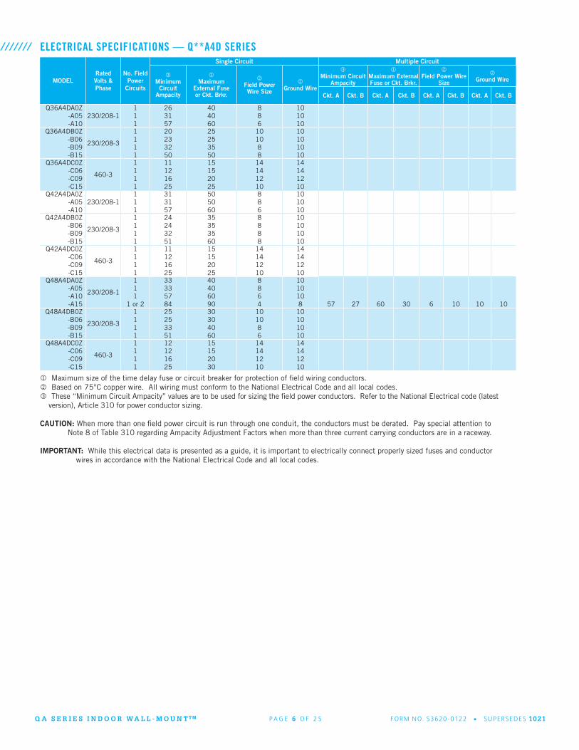
ELECTRICAL SPECIFICATIONS — Q**A4D SERIES///////
Maximum size of the time delay fuse or circuit breaker for protection of field wiring conductors. Based on 75°C copper wire. All wiring must conform to the National Electrical Code and all local codes. These “Minimum Circuit Ampacity” values are to be used for sizing the field power conductors. Refer to the National Electrical code (latest
version), Article 310 for power conductor sizing.
CAUTION: When more than one field power circuit is run through one conduit, the conductors must be derated. Pay special attention to Note 8 of Table 310 regarding Ampacity Adjustment Factors when more than three current carrying conductors are in a raceway.
IMPORTANT: While this electrical data is presented as a guide, it is important to electrically connect properly sized fuses and conductor wires in accordance with the National Electrical Code and all local codes.

Q A S E R I E S I N D O O R W A L L - M O U N T T M P A G E 7 O F 2 5 FO R M N O. S362 0 - 0122 • S U P E R S E D E S 1021
COOLING CAPACITY DATA - STANDARD OPERATION AT OUTDOOR TEMPERATURE///////
MODEL RETURN AIR(DB/WB) COOLING CAPACITY 75°F 80°F 85°F 90°F 95°F 100°F 105°F 110°F 115°F 120°F 125°F
Q36AD4A
75/62Total Cooling
Sensible Cooling38,50030,200
36,30028,800
34,20027,500
32,30026,300
30,60025,400
29,00024,600
27,70023,800
26,40023,200
25,30022,800
24,40022,500
23,50022,300
80/67Total Cooling
Sensible Cooling41,10029,300
39,50028,200
37,90027,200
36,50026,300
35,00025,600
33,80025,000
32,60024,400
31,50024,000
30,40023,700
29,50023,500
28,60023,500
85/72Total Cooling
Sensible Cooling49,00030,000
46,20028,600
43,50027,400
41,20026,100
39,00025,100
37,00024,200
35,20023,300
33,50022,500
32,00021,900
30,70021,300
29,40020,800
Q42AD4A
75/62Total Cooling
Sensible Cooling44,00030,800
41,30030,200
38,80029,800
36,70029,300
34,70028,900
33,00028,300
31,50027,900
30,30027,400
29,30026,900
28,50026,500
27,80026,000
80/67Total Cooling
Sensible Cooling47,00029,800
45,00029,600
43,10029,500
41,40029,300
39,50029,100
38,40028,800
37,20028,600
36,10028,300
35,20028,000
34,50027,700
33,90027,300
85/72Total Cooling
Sensible Cooling56,00030,500
52,60030,100
49,50029,700
46,80029,100
44,20027,900
42,00027,900
40,10027,300
28,40026,600
37,00025,800
35,90025,000
34,90024,200
Q48AD4A
75/62Total Cooling
Sensible Cooling50,10038,400
47,60037,300
45,30036,100
43,10035,000
40,90033,900
39,00032,900
37,10031,900
35,40031,000
33,70030,000
32,20029,200
30,70028,300
80/67Total Cooling
Sensible Cooling53,50037,200
51,90036,500
50,30035,700
48,70035,000
47,00034,200
45,40033,500
43,80032,700
42,20032,000
40,60031,200
39,00030,500
37,40029,800
85/72Total Cooling
Sensible Cooling63,70038,100
60,70037,100
57,80035,900
55,00034,800
52,20033,600
49,70032,400
47,20031,200
44,90030,000
42,70028,800
40,50027,600
38,50026,400
Below 65°F, unit requires a factory or field installed low ambient control. Outdoor temperatures shown are measured at the condenser section air inlet. Return air temperature °F.
COOLING CAPACITY DATA - BALANCED CLIMATE OPERATION AT OUTDOOR TEMPERATURES///////
Below 65°F, unit requires a factory or field installed low ambient control. Outdoor temperatures shown are measured at the condenser section air inlet. Return air temperature °F.
MODEL RETURN AIR(DB/WB) COOLING CAPACITY 75°F 80°F 85°F 90°F 95°F 100°F 105°F 110°F 115°F 120°F 125°F
Q36AD4A
75/62
Total CoolingSensible CoolingLatent Cooling
H2O / Hr.
34,80024,9009,9009.31
33,50024,3009,2008.66
32,30023,7008,6008.09
31,10023,0008,1007.62
29,90022,4007,5007.06
28,70021,8006,9006.49
27,60021,4006,2005.83
26,50020,8005,7005.36
25,40020,2005,2004.89
24,40019,7004,7004.42
23,30019,2004,1003.86
80/67
Total CoolingSensible CoolingLatent Cooling
H2O / Hr.
37,10024,10013,00012.26
36,50023,80012,70011.98
35,80023,40012,40011.70
35,10023,00012,10011.42
34,30022,60011,70011.04
33,40022,20011,20010.57
32,50021,90010,60010.00
31,60021,50010,100
9.53
30,60021,0009,6009.06
29,50020,6008,9008.40
28,40020,2008,2007.74
85/72
Total CoolingSensible CoolingLatent Cooling
H2O / Hr.
44,20024,70019,50018.44
42,70024,20018,50017.50
41,10023,50017,60016.65
39,70022,90016,80015.89
38,10022,20015,90015.04
36,60021,50015,10014.28
35,10020,90014,20013.43
33,60020,20013,40012.67
32,20019,40012,80012.11
30,70018,60012,10011.45
29,20017,90011,30010.69
Q42AD4A
75/62
Total CoolingSensible CoolingLatent Cooling
H2O / Hr.
41,20028,50012,70011.95
39,20027,80011,40010.73
37,40027,00010,400
9.78
35,70026,3009,4008.84
34,10025,6008,5008.00
32,60024,9007,7007.24
31,40024,3007,1006.68
30,20023,6006,6006.21
29,10023,0006,1005.74
28,20022,4005,8005.46
27,300 21,9005,4005.08
80/67
Total CoolingSensible CoolingLatent Cooling
H2O / Hr.
44,00027,60016,40015.47
42,70027,20015,50014.62
41,50026,70014,80013.96
40,30026,30014,00013.21
39,10025,80013,30012.55
38,00025,30012,70011.98
37,00024,90012,10011.42
36,00024,40011,60010.94
35,00023,90011,10010.47
34,10023,40010,70010.09
33,20023,00010,200
9.62
85/72
Total CoolingSensible CoolingLatent Cooling
H2O / Hr.
52,40028,30024,10022.80
49,90027,60022,30021.09
47,70026,80020,90019.77
45,50026,10019,40018.35
43,50025,30018,20017.21
41,60024,50017,10016.17
39,90023,80016,10015.23
38,30022,90015,40014.57
36,80022,00014,80014.00
35,50021,20014,30013.53
34,20020,40013,80013.05
Q48AD4A
75/62
Total CoolingSensible CoolingLatent Cooling
H2O / Hr.
46,30033,00013,30012.51
44,30032,20012,10011.38
42,40031,20011,20010.54
40,60030,30010,300
9.69
38,90029,5009,4008.84
37,10028,6008,5008.00
35,40027,8007,6007.15
33,80026,9006,9006.49
32,20026,1006,1005.74
30,60025,2005,4005.08
29,20024,3004,9004.61
80/67
Total CoolingSensible CoolingLatent Cooling
H2O / Hr.
49,4003,200
17,40016.42
48,30031,50016,80015.85
47,10030,90016,20015.28
45,90030,30015,60014.72
44,60029,70014,90014.06
43,20029,10014,10013.30
41,80028,50013,30012.55
40,30027,80012,50011.79
38,70027,10011,60010.94
37,10026,40010,70010.09
35,50025,6009,9009.34
85/72
Total CoolingSensible CoolingLatent Cooling
H2O / Hr.
58,90032,80026,10024.69
56,50032,00024,50023.17
54,10031,10023,00021.76
21,80030,10021,70020.53
49,60029,20020,40019.30
47,30028,20019,10018.07
45,10027,20017,90016.93
42,90026,10016,80015.89
40,70025,00015,70014.85
38,60023,90014,70013.90
36,50022,70013,80013.05
Q A S E R I E S I N D O O R W A L L - M O U N T T M P A G E 8 O F 2 5 FO R M N O. S362 0 - 0122 • S U P E R S E D E S 1021
NOMINALKW
AT 240V (1) AT 208V (1) AT 480V (2) AT 460V (2)
KW 1-PH AMPS
3-PH AMPS BTUH KW 1-PH
AMPS3-PH AMPS KW KW 3-PH
AMPS KW KW 3-PH AMPS KW
4.0 4.0 16.7 13,652 3.00 14.4 10,239
5.0 5.0 20.8 17,065 3.75 18.0 12,799
6.0 6.0 14.4 20,478 4.50 12.5 15,359 6.0 7.2 20,478 5.52 6.9 18,840
8.0 8.0 33.3 27,304 6.00 28.8 20,478
9.0 9.0 21.7 30,717 6.75 18.7 23,038 9.0 10.8 30,717 8.28 10.4 28,260
10.0 10.0 41.7 34,130 7.50 36.1 25,598
15.0 15.0 62.5 36.1 51,195 11.25 54.1 31.2 38,396 15.0 18.0 51,195 13.80 17.3 47,099
18.0 18.0 43.3 61,434 13.50 37.5 46,076 18.0 21.7 61,434 16.56 20.8 56,519
20.0 20.0 83.3 68,260 15.00 72.1 51,195
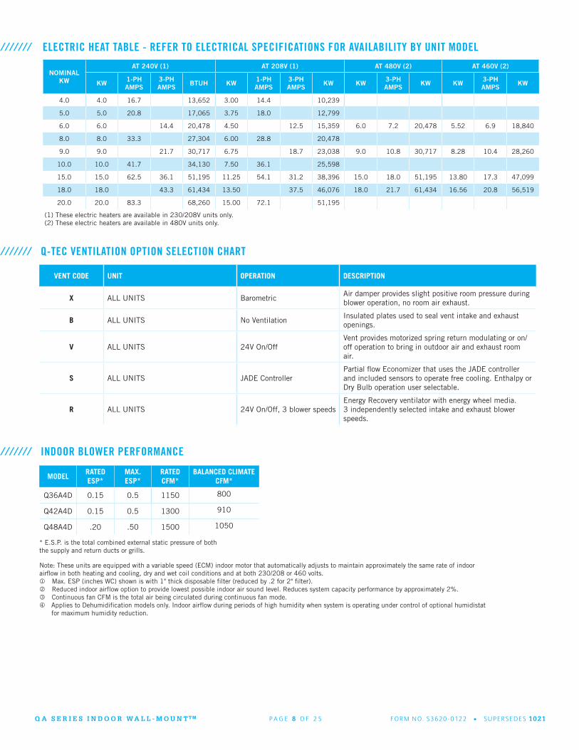
(1) These electric heaters are available in 230/208V units only.(2) These electric heaters are available in 480V units only.
ELECTRIC HEAT TABLE - REFER TO ELECTRICAL SPECIFICATIONS FOR AVAILABILITY BY UNIT MODEL///////
VENT CODE UNIT OPERATION DESCRIPTION
X ALL UNITS BarometricAir damper provides slight positive room pressure during blower operation, no room air exhaust.
B ALL UNITS No VentilationInsulated plates used to seal vent intake and exhaust openings.
V ALL UNITS 24V On/OffVent provides motorized spring return modulating or on/off operation to bring in outdoor air and exhaust room air.
S ALL UNITS JADE ControllerPartial flow Economizer that uses the JADE controller and included sensors to operate free cooling. Enthalpy or Dry Bulb operation user selectable.
R ALL UNITS 24V On/Off, 3 blower speedsEnergy Recovery ventilator with energy wheel media. 3 independently selected intake and exhaust blower speeds.
/////// Q-TEC VENTILATION OPTION SELECTION CHART
/////// INDOOR BLOWER PERFORMANCE
MODELRATEDESP*
MAX.ESP*
RATEDCFM*
BALANCED CLIMATECFM*
Q36A4D 0.15 0.5 1150 800
Q42A4D 0.15 0.5 1300 910
Q48A4D .20 .50 1500 1050
* E.S.P. is the total combined external static pressure of both the supply and return ducts or grills.
Note: These units are equipped with a variable speed (ECM) indoor motor that automatically adjusts to maintain approximately the same rate of indoor airflow in both heating and cooling, dry and wet coil conditions and at both 230/208 or 460 volts. Max. ESP (inches WC) shown is with 1" thick disposable filter (reduced by .2 for 2" filter). Reduced indoor airflow option to provide lowest possible indoor air sound level. Reduces system capacity performance by approximately 2%. Continuous fan CFM is the total air being circulated during continuous fan mode. Applies to Dehumidification models only. Indoor airflow during periods of high humidity when system is operating under control of optional humidistat for maximum humidity reduction.
Q A S E R I E S I N D O O R W A L L - M O U N T T M P A G E 9 O F 2 5 FO R M N O. S362 0 - 0122 • S U P E R S E D E S 1021
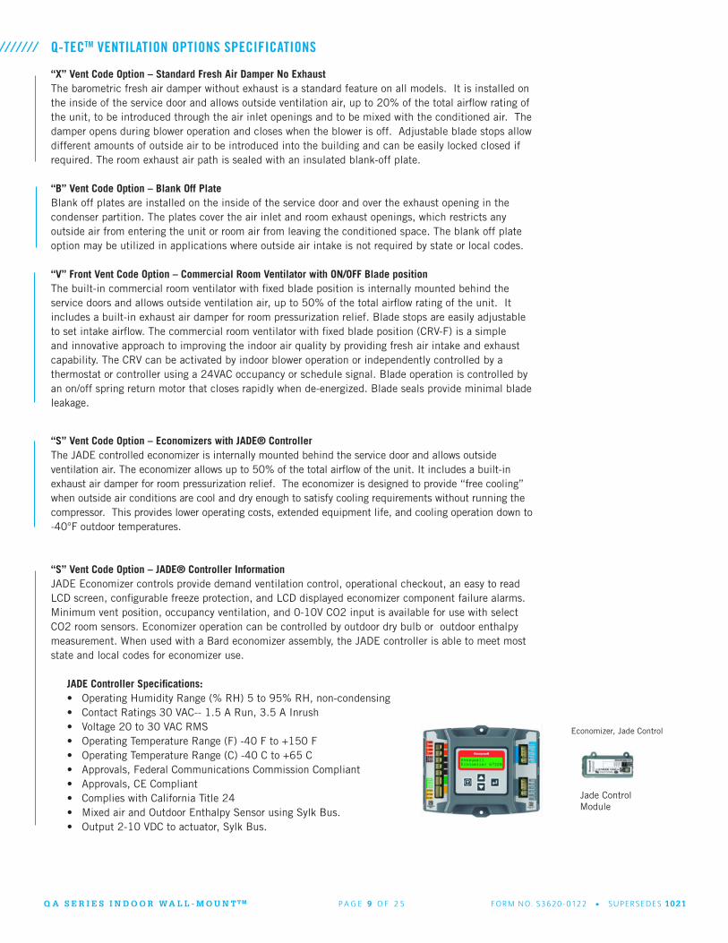
“X” Vent Code Option – Standard Fresh Air Damper No ExhaustThe barometric fresh air damper without exhaust is a standard feature on all models. It is installed on the inside of the service door and allows outside ventilation air, up to 20% of the total airflow rating of the unit, to be introduced through the air inlet openings and to be mixed with the conditioned air. The damper opens during blower operation and closes when the blower is off. Adjustable blade stops allow different amounts of outside air to be introduced into the building and can be easily locked closed if required. The room exhaust air path is sealed with an insulated blank-off plate.
“B” Vent Code Option – Blank Off Plate Blank off plates are installed on the inside of the service door and over the exhaust opening in the condenser partition. The plates cover the air inlet and room exhaust openings, which restricts any outside air from entering the unit or room air from leaving the conditioned space. The blank off plate option may be utilized in applications where outside air intake is not required by state or local codes.
“V” Front Vent Code Option – Commercial Room Ventilator with ON/OFF Blade positionThe built-in commercial room ventilator with fixed blade position is internally mounted behind the service doors and allows outside ventilation air, up to 50% of the total airflow rating of the unit. It includes a built-in exhaust air damper for room pressurization relief. Blade stops are easily adjustable to set intake airflow. The commercial room ventilator with fixed blade position (CRV-F) is a simple and innovative approach to improving the indoor air quality by providing fresh air intake and exhaust capability. The CRV can be activated by indoor blower operation or independently controlled by a thermostat or controller using a 24VAC occupancy or schedule signal. Blade operation is controlled by an on/off spring return motor that closes rapidly when de-energized. Blade seals provide minimal blade leakage.
Q-TECTM VENTILATION OPTIONS SPECIFICATIONS///////
“S” Vent Code Option – Economizers with JADE® ControllerThe JADE controlled economizer is internally mounted behind the service door and allows outside ventilation air. The economizer allows up to 50% of the total airflow of the unit. It includes a built-in exhaust air damper for room pressurization relief. The economizer is designed to provide “free cooling” when outside air conditions are cool and dry enough to satisfy cooling requirements without running the compressor. This provides lower operating costs, extended equipment life, and cooling operation down to -40°F outdoor temperatures.
“S” Vent Code Option – JADE® Controller InformationJADE Economizer controls provide demand ventilation control, operational checkout, an easy to read LCD screen, configurable freeze protection, and LCD displayed economizer component failure alarms. Minimum vent position, occupancy ventilation, and 0-10V CO2 input is available for use with select CO2 room sensors. Economizer operation can be controlled by outdoor dry bulb or outdoor enthalpy measurement. When used with a Bard economizer assembly, the JADE controller is able to meet most state and local codes for economizer use.
JADE Controller Specifications:• Operating Humidity Range (% RH) 5 to 95% RH, non-condensing• Contact Ratings 30 VAC-- 1.5 A Run, 3.5 A Inrush• Voltage 20 to 30 VAC RMS• Operating Temperature Range (F) -40 F to +150 F• Operating Temperature Range (C) -40 C to +65 C• Approvals, Federal Communications Commission Compliant• Approvals, CE Compliant• Complies with California Title 24• Mixed air and Outdoor Enthalpy Sensor using Sylk Bus.• Output 2-10 VDC to actuator, Sylk Bus.
Jade Control Module
Economizer, Jade Control

Q A S E R I E S I N D O O R W A L L - M O U N T T M P A G E 1 0 O F 2 5 FO R M N O. S362 0 - 0122 • S U P E R S E D E S 1021
“R” Vent Code Option – Energy Recovery Ventilator The energy recovery ventilator (ERV) is a highly innovative approach to meeting indoor air quality ventilation requirements as established by ANSI/ASHRAE Standard 62.1. The ERV allows up to 450 CFM (depending upon model) of fresh air and exhaust through the unit while maintaining superior indoor comfort and humidity levels. In most cases this can be accomplished without increasing equipment sizing or operating costs. Heat transfer efficiency is up to 67% during summer and 75% during winter conditions.
The ERV consists of a unique “rotary energy recovery cassette” that provides effective sensible and latent heat transfer capabilities during summer and winter conditions. Various control schemes are addressed including limiting ventilation during building occupancy only. The ERV is designed to be internally mounted behind the service door, and includes independent blowers for intake air and exhaust air balancing.
Q-TECTM VENTILATION OPTIONS SPECIFICATIONS (continued)
Typical load reductions for ERV-F3
///////
Q A S E R I E S I N D O O R W A L L - M O U N T T M P A G E 1 1 O F 2 5 FO R M N O. S362 0 - 0122 • S U P E R S E D E S 1021
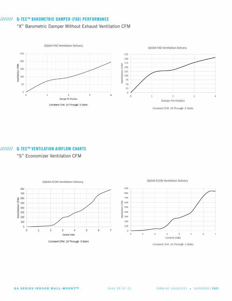
Q-TECTM BAROMETRIC DAMPER (FAD) PERFORMANCE///////“X” Barometric Damper Without Exhaust Ventilation CFM
Q36A4 FAD Ventilation DeliveryQ42A4 FAD Ventilation Delivery
Q-TECTM VENTILATION AIRFLOW CHARTS///////“S” Economizer Ventilation CFM
Q36A4 ECON Ventilation Delivery Q42A4 ECON Ventilation Delivery
Q A S E R I E S I N D O O R W A L L - M O U N T T M P A G E 1 2 O F 2 5 FO R M N O. S362 0 - 0122 • S U P E R S E D E S 1021
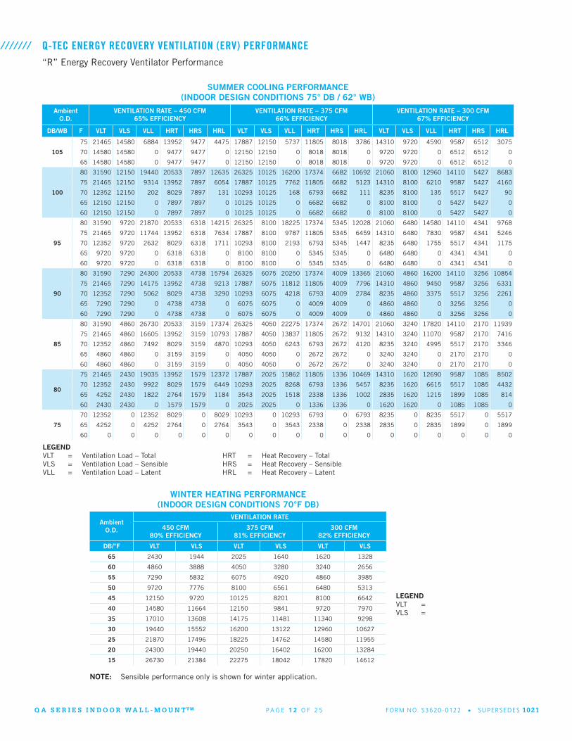
Q-TEC ENERGY RECOVERY VENTILATION (ERV) PERFORMANCE“R” Energy Recovery Ventilator Performance
///////
SUMMER COOLING PERFORMANCE(INDOOR DESIGN CONDITIONS 75° DB / 62° WB)
LEGENDVLT = Ventilation Load – Total HRT = Heat Recovery – TotalVLS = Ventilation Load – Sensible HRS = Heat Recovery – SensibleVLL = Ventilation Load – Latent HRL = Heat Recovery – Latent
WINTER HEATING PERFORMANCE(INDOOR DESIGN CONDITIONS 70°F DB)
NOTE: Sensible performance only is shown for winter application.
LEGENDVLT = VLS =
AmbientO.D.
VENTILATION RATE – 450 CFM65% EFFICIENCY
VENTILATION RATE – 375 CFM66% EFFICIENCY
VENTILATION RATE – 300 CFM67% EFFICIENCY
DB/WB F VLT VLS VLL HRT HRS HRL VLT VLS VLL HRT HRS HRL VLT VLS VLL HRT HRS HRL
105
75 21465 14580 6884 13952 9477 4475 17887 12150 5737 11805 8018 3786 14310 9720 4590 9587 6512 3075
70 14580 14580 0 9477 9477 0 12150 12150 0 8018 8018 0 9720 9720 0 6512 6512 0
65 14580 14580 0 9477 9477 0 12150 12150 0 8018 8018 0 9720 9720 0 6512 6512 0
100
80 31590 12150 19440 20533 7897 12635 26325 10125 16200 17374 6682 10692 21060 8100 12960 14110 5427 8683
75 21465 12150 9314 13952 7897 6054 17887 10125 7762 11805 6682 5123 14310 8100 6210 9587 5427 4160
70 12352 12150 202 8029 7897 131 10293 10125 168 6793 6682 111 8235 8100 135 5517 5427 90
65 12150 12150 0 7897 7897 0 10125 10125 0 6682 6682 0 8100 8100 0 5427 5427 0
60 12150 12150 0 7897 7897 0 10125 10125 0 6682 6682 0 8100 8100 0 5427 5427 0
95
80 31590 9720 21870 20533 6318 14215 26325 8100 18225 17374 5345 12028 21060 6480 14580 14110 4341 9768
75 21465 9720 11744 13952 6318 7634 17887 8100 9787 11805 5345 6459 14310 6480 7830 9587 4341 5246
70 12352 9720 2632 8029 6318 1711 10293 8100 2193 6793 5345 1447 8235 6480 1755 5517 4341 1175
65 9720 9720 0 6318 6318 0 8100 8100 0 5345 5345 0 6480 6480 0 4341 4341 0
60 9720 9720 0 6318 6318 0 8100 8100 0 5345 5345 0 6480 6480 0 4341 4341 0
90
80 31590 7290 24300 20533 4738 15794 26325 6075 20250 17374 4009 13365 21060 4860 16200 14110 3256 10854
75 21465 7290 14175 13952 4738 9213 17887 6075 11812 11805 4009 7796 14310 4860 9450 9587 3256 6331
70 12352 7290 5062 8029 4738 3290 10293 6075 4218 6793 4009 2784 8235 4860 3375 5517 3256 2261
65 7290 7290 0 4738 4738 0 6075 6075 0 4009 4009 0 4860 4860 0 3256 3256 0
60 7290 7290 0 4738 4738 0 6075 6075 0 4009 4009 0 4860 4860 0 3256 3256 0
85
80 31590 4860 26730 20533 3159 17374 26325 4050 22275 17374 2672 14701 21060 3240 17820 14110 2170 11939
75 21465 4860 16605 13952 3159 10793 17887 4050 13837 11805 2672 9132 14310 3240 11070 9587 2170 7416
70 12352 4860 7492 8029 3159 4870 10293 4050 6243 6793 2672 4120 8235 3240 4995 5517 2170 3346
65 4860 4860 0 3159 3159 0 4050 4050 0 2672 2672 0 3240 3240 0 2170 2170 0
60 4860 4860 0 3159 3159 0 4050 4050 0 2672 2672 0 3240 3240 0 2170 2170 0
80
75 21465 2430 19035 13952 1579 12372 17887 2025 15862 11805 1336 10469 14310 1620 12690 9587 1085 8502
70 12352 2430 9922 8029 1579 6449 10293 2025 8268 6793 1336 5457 8235 1620 6615 5517 1085 4432
65 4252 2430 1822 2764 1579 1184 3543 2025 1518 2338 1336 1002 2835 1620 1215 1899 1085 814
60 2430 2430 0 1579 1579 0 2025 2025 0 1336 1336 0 1620 1620 0 1085 1085 0
75
70 12352 0 12352 8029 0 8029 10293 0 10293 6793 0 6793 8235 0 8235 5517 0 5517
65 4252 0 4252 2764 0 2764 3543 0 3543 2338 0 2338 2835 0 2835 1899 0 1899
60 0 0 0 0 0 0 0 0 0 0 0 0 0 0 0 0 0 0
AmbientO.D.
VENTILATION RATE
450 CFM80% EFFICIENCY
375 CFM81% EFFICIENCY
300 CFM82% EFFICIENCY
DB/°F VLT VLS VLT VLS VLT VLS
65 2430 1944 2025 1640 1620 1328
60 4860 3888 4050 3280 3240 2656
55 7290 5832 6075 4920 4860 3985
50 9720 7776 8100 6561 6480 5313
45 12150 9720 10125 8201 8100 6642
40 14580 11664 12150 9841 9720 7970
35 17010 13608 14175 11481 11340 9298
30 19440 15552 16200 13122 12960 10627
25 21870 17496 18225 14762 14580 11955
20 24300 19440 20250 16402 16200 13284
15 26730 21384 22275 18042 17820 14612

Q A S E R I E S I N D O O R W A L L - M O U N T T M P A G E 1 3 O F 2 5 FO R M N O. S362 0 - 0122 • S U P E R S E D E S 1021
Cabinet Finish OptionsUnit models are available in Beige, Buckeye Gray, and Vinyl Coated Steel.
Painted cabinet construction is comprised of 20 gauge Zinc coated steel. Parts are cleaned, rinsed, sealed, and dried before a polyurethane primer is applied. The cabinet coating is completed with a baked on textured enamel. The resulting finish is designed to withstand 1000 hours of salt spray tests per ASTM B117-03.
Vinyl coated steel cabinet construction uses darker color Slate front panels and lighter color Platinum side panels. The coated finish is textured and resistant to marring and scratching.
All QH units use tamper resistant screws for securing doors and panels. Keyed entry fasteners are provided for the front doors.
Green Fin Hydrophilic Evaporator Coils Standard On All UnitsBard Q-TEC products include a green protective coating applied to the aluminum fin stock used for the evaporator coil. The evaporator coil coating is hydrophilic (attracts water) and allows for proper condensate drainage along with mild corrosion protection. Resistance to corrosive agents include ammonia, sodium hydroxide, sodium chloride, acidic solutions and solvents.
Note: The green fin hydrophilic evaporator coil is not a replacement for technicoat coil coating. Green fin stock does provide additional coil protection, but technicoat is recommended for harsh indoor environments where strong acidic or alkali chemicals are being used.
X—Beige 4—Gray
CABINET AND COIL OPTIONS///////
V—Slate front/Platinum sides
Hydrophilic Green Coil(standard)
Q A S E R I E S I N D O O R W A L L - M O U N T T M P A G E 1 4 O F 2 5 FO R M N O. S362 0 - 0122 • S U P E R S E D E S 1021
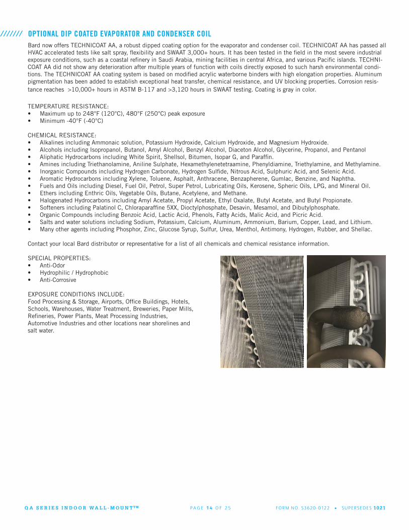
OPTIONAL DIP COATED EVAPORATOR AND CONDENSER COIL///////Bard now offers TECHNICOAT AA, a robust dipped coating option for the evaporator and condenser coil. TECHNICOAT AA has passed all HVAC accelerated tests like salt spray, flexibility and SWAAT 3,000+ hours. It has been tested in the field in the most severe industrial exposure conditions, such as a coastal refinery in Saudi Arabia, mining facilities in central Africa, and various Pacific islands. TECHNI-COAT AA did not show any deterioration after multiple years of function with coils directly exposed to such harsh environmental condi-tions. The TECHNICOAT AA coating system is based on modified acrylic waterborne binders with high elongation properties. Aluminum pigmentation has been added to establish exceptional heat transfer, chemical resistance, and UV blocking properties. Corrosion resis-tance reaches >10,000+ hours in ASTM B-117 and >3,120 hours in SWAAT testing. Coating is gray in color.
TEMPERATURE RESISTANCE:• Maximum up to 248°F (120°C), 480°F (250°C) peak exposure • Minimum -40°F (-40°C)
CHEMICAL RESISTANCE:• Alkalines including Ammonaic solution, Potassium Hydroxide, Calcium Hydroxide, and Magnesium Hydroxide.• Alcohols including Isopropanol, Butanol, Amyl Alcohol, Benzyl Alcohol, Diaceton Alcohol, Glycerine, Propanol, and Pentanol• Aliphatic Hydrocarbons including White Spirit, Shellsol, Bitumen, Isopar G, and Paraffin.• Amines including Triethanolamine, Aniline Sulphate, Hexamethylenetetraamine, Phenyldiamine, Triethylamine, and Methylamine.• Inorganic Compounds including Hydrogen Carbonate, Hydrogen Sulfide, Nitrous Acid, Sulphuric Acid, and Selenic Acid.• Aromatic Hydrocarbons including Xylene, Toluene, Asphalt, Anthracene, Benzapherene, Gumlac, Benzine, and Naphtha.• Fuels and Oils including Diesel, Fuel Oil, Petrol, Super Petrol, Lubricating Oils, Kerosene, Spheric Oils, LPG, and Mineral Oil.• Ethers including Enthric Oils, Vegetable Oils, Butane, Acetylene, and Methane.• Halogenated Hydrocarbons including Amyl Acetate, Propyl Acetate, Ethyl Oxalate, Butyl Acetate, and Butyl Propionate.• Softeners including Palatinol C, Chloraparaffine 5XX, Dioctylphosphate, Desavin, Mesamol, and Dibutylphosphate.• Organic Compounds including Benzoic Acid, Lactic Acid, Phenols, Fatty Acids, Malic Acid, and Picric Acid.• Salts and water solutions including Sodium, Potassium, Calcium, Aluminum, Ammonium, Barium, Copper, Lead, and Lithium.• Many other agents including Phosphor, Zinc, Glucose Syrup, Sulfur, Urea, Menthol, Antimony, Hydrogen, Rubber, and Shellac.
Contact your local Bard distributor or representative for a list of all chemicals and chemical resistance information. SPECIAL PROPERTIES:• Anti-Odor • Hydrophilic / Hydrophobic • Anti-Corrosive
EXPOSURE CONDITIONS INCLUDE: Food Processing & Storage, Airports, Office Buildings, Hotels, Schools, Warehouses, Water Treatment, Breweries, Paper Mills, Refineries, Power Plants, Meat Processing Industries, Automotive Industries and other locations near shorelines and salt water.

Q A S E R I E S I N D O O R W A L L - M O U N T T M P A G E 1 5 O F 2 5 FO R M N O. S362 0 - 0122 • S U P E R S E D E S 1021
Q-TEC FACTORY INSTALLED CONTROLS OPTIONSFactory installed controls are provided by Bard to enhance a Q-TEC product before it is shipped. All Q-TEC products are shipped with an auto-reset high pressure switch and an auto-reset low pressure switch to help protect refrigeration components. A compressor control module with adjustable voltage protection, delay on make and break, and high/low pressure diagnostics is also standard.
CONTROL CODE DESCRIPTION OF FACTORY INSTALLED COMPONENTS
X Hi Pressure Switch, Low Pressure Switch, Compressor Control Module.
E Hi Pressure Switch, Low Pressure Switch, Compressor Control Module, Low Ambient Control
///////
Hi Pressure Control (HPC) - The high pressure control provides a means of protecting the refrigeration circuit when high system pressures occur. It is an auto-reset device that is connected to the Compressor Control Module. When activated, the compressor is disabled until pressures reach an acceptable level. If activated twice in the same cooling call, compressor operation is locked out until the cooling call is interrupted.
Low Pressure Control (LPC) - The low pressure control provides a means of protecting the refrigeration circuit when extremely low system pressures occur. It is an auto-reset device that is connected to the Compressor Control Module. When activated, the compressor is disabled until pressures reach an acceptable level.
Low Ambient Control (LAC) - The low ambient control pressure sensor is attached to the suction line of the system, and monitors low side system pressure. Operation of the LAC occurs as outdoor temperatures drop below the 65°F to 50°F range. On/Off and modulating controls are used. On/Off LAC operation cycles the condenser fan operation based on outdoor temperature. Modulating LAC operation is factory adjusted and slows the condenser fan speed RPM based on outdoor temperature.
OPTIONAL CONTROLS AND KIT COMPONENT DEFINITIONS///////
Q A S E R I E S I N D O O R W A L L - M O U N T T M P A G E 1 6 O F 2 5 FO R M N O. S362 0 - 0122 • S U P E R S E D E S 1021
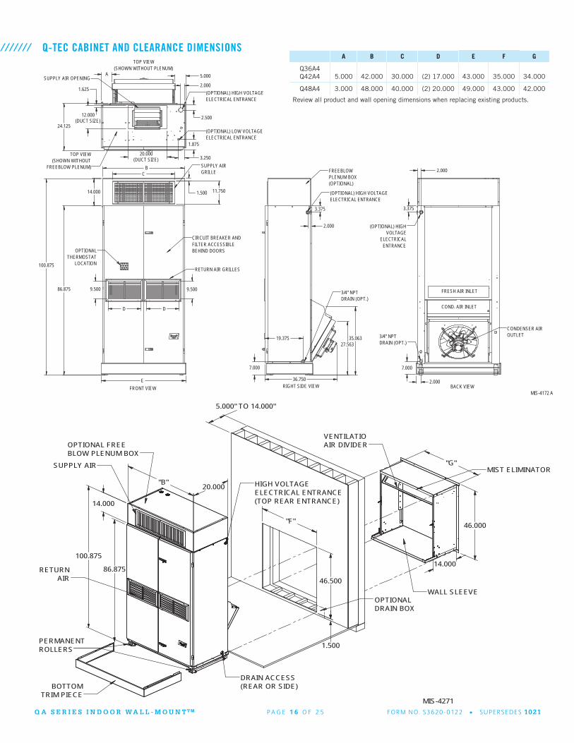
Q-TEC CABINET AND CLEARANCE DIMENSIONS///////A B C D E F G
Q36A4Q42A4 5.000 42.000 30.000 (2) 17.000 43.000 35.000 34.000
Q48A4 3.000 48.000 40.000 (2) 20.000 49.000 43.000 42.000
20.000(DUCT SIZE)
12.000(DUCT SIZE)
7.000
CONDENSER AIROUTLET
COND. AIR INLET
ENTRANCEELECTRICAL
BACK VIEW
FRESH AIR INLET
(OPTIONAL) HIGHVOLTAGE
3/4" NPTDRAIN (OPT.)
3.375
7.000
2.000
2.000
(OPTIONAL) HIGH VOLTAGE
FREEBLOW PLENUM)
(OPTIONAL) LOW VOLTAGEELECTRICAL ENTRANCE
ELECTRICAL ENTRANCE
TOP VIEW(SHOWN WITHOUT
SUPPLY AIR OPENING
TOP VIEW(SHOWN WITHOUT PLENUM)
2.000 1.625
5.000
1.875
3.250
24.125 2.500
A
(OPTIONAL) HIGH VOLTAGEELECTRICAL ENTRANCE
(OPTIONAL)PLENUM BOX
RIGHT SIDE VIEW
FREEBLOW
3/4" NPTDRAIN (OPT.)
36.750
27.563
2.000
3.375
19.375 35.063
MIS-4172 A
GRILLE
LOCATIONTHERMOSTAT
SUPPLY AIR
FRONT VIEW
BEHIND DOORSOPTIONAL
CIRCUIT BREAKER ANDFILTER ACCESSIBLE
RETURN AIR GRILLES
11.750
D
14.000
B C
D
9.500
100.875
E
86.875
1.500
9.500
Review all product and wall opening dimensions when replacing existing products.
MIS-4271
OPTIONALDRAIN BOX
BOTTOMTRIM PIECE
SUPPLY AIR
VENTILATIO
AIR
BLOW PLENUM BOX
RETURN
ELECTRICAL ENTRANCE
AIR DIVIDER
HIGH VOLTAGE
(TOP REAR ENTRANCE)
WALL SLEEVE
OPTIONAL FREE
MIST ELIMINATOR
PERMANENTROLLERS
DRAIN ACCESS(REAR OR SIDE)
"F"
1.500
46.500
100.875
86.875
"B"
46.000
14.000
20.000
"G"
14.000
5.000" TO 14.000"

Q A S E R I E S I N D O O R W A L L - M O U N T T M P A G E 1 7 O F 2 5 FO R M N O. S362 0 - 0122 • S U P E R S E D E S 1021
Q-TEC WALL SLEEVE OPTIONS///////
Wall Sleeve UnitWall Depth
Description
QWS42AQWS48A
Q36A, Q42AQ48A
14” Sleeve designed for 35” x 48” wall opening in 14” or less depth wall.Sleeve designed for 43” x 48” wall opening in 14” or less depth wall.
QWS42A-16QWS48A-16
Q36A, Q42AQ48A
16” Sleeve designed for 35” x 48” wall opening in 16” depth wall.Sleeve designed for 43” x 48” wall opening in 16” depth wall.
QWS42A-19QWS48A-19
Q36A, Q42AQ48A
19” Sleeve designed for 35” x 48” wall opening in 19” depth wall.Sleeve designed for 43” x 48” wall opening in 19” depth wall.
QWS42A-20QWS48A-20
Q36A, Q42AQ48A
20” Sleeve designed for 35” x 48” wall opening in 20” depth wall.Sleeve designed for 43” x 48” wall opening in 20” depth wall.
QWS42A-23QWS48A-23
Q36A, Q42AQ48A
23” Sleeve designed for 35” x 48” wall opening in 23” depth wall.Sleeve designed for 43” x 48” wall opening in 23” depth wall.
QWS42A-30QWS48A-30
Q36A, Q42AQ48A
30” Sleeve designed for 35” x 48” wall opening in 30” depth wall.Sleeve designed for 43” x 48” wall opening in 30” depth wall.
QWS42A-H19QWS48A-H19
Q36A, Q42AQ48A
19” Special sleeve design for hurricane louver. 19” wall depth or less required.
The Q-TEC wall sleeve is a required accessory for the QH unit. It allows for condenser fan air intake and exhaust used during cooling and heating operation. It also provides a path for outdoor ventilation air intake and room air exhaust when using the QH optional ventilation options. It is important to use Bard approved wall sleeve and louver designs to ensure proper condenser airflow and ventilation airflow occurs. Various wall sleeve depths are available to match the building wall depth or to allow QH installation in buildings where the unit will need to have a gap between the wall and the unit.
When performing a replacement installation where you intend to reuse the existing wall sleeve a condenser section blank off plate is required to ensure adequate seal between the condenser inlet and the outdoor louver.
Plate Kit Unit Wall Depth Description
Q3TBOP-16Q4TBOP-16
Q36A, Q42AQ48A
16” Fill plate for 16” wall sleeve
Q3TBOP-20Q4TBOP-20
Q36A, Q42AQ48A
19-20” Fill plate for 19” & 20” wall sleeves
Q3TBOP-23Q4TBOP-23
Q36A, Q42AQ48A
23” Fill plate for 23” wall sleeve
Q3TBOP-30Q4TBOP-30
Q36A, Q42AQ48A
30” Fill plate for 30” wall sleeve
MIS-4247

Q A S E R I E S I N D O O R W A L L - M O U N T T M P A G E 1 8 O F 2 5 FO R M N O. S362 0 - 0122 • S U P E R S E D E S 1021
Q-TEC WALL LOUVER OPTIONS///////
Wall Louver Unit Inner Louver Size Description
QLS2-10QLS4-10
Q36A, Q42AQ48A
32.5 x 45.5”40.5 x 45.5”
Aluminum Finish
QLS2-20QLS4-20
Q36A, Q42AQ48A
32.5 x 45.5”40.5 x 45.5”
Medium Bronze
QLS2-30QLS4-30
Q36A, Q42AQ48A
32.5 x 45.5”40.5 x 45.5”
Dark Bronze
QLS2-12QLS4-12
Q36A, Q42AQ48A
32.5 x 45.5”40.5 x 45.5”
Arctic White
QLS2-14QLS4-14
Q36A, Q42AQ48A
32.5 x 45.5”40.5 x 45.5”
Storm White
QLS2-18QLS4-18
Q36A, Q42AQ48A
32.5 x 45.5”40.5 x 45.5”
Milano Beige
QLS2-40QLS4-40
Q36A, Q42AQ48A
32.5 x 45.5”40.5 x 45.5”
School Bus Yellow
QLS2-42QLS4-42
Q36A, Q42AQ48A
32.5 x 45.5”40.5 x 45.5”
Florida Orange
QLS2-44QLS4-44
Q36A, Q42AQ48A
32.5 x 45.5”40.5 x 45.5”
School House Red
QLS2-46QLS4-46
Q36A, Q42AQ48A
32.5 x 45.5”40.5 x 45.5”
Chili Red
QLS2-50QLS4-50
Q36A, Q42AQ48A
32.5 x 45.5”40.5 x 45.5”
Deep Sea Blue
QLS2-52QLS4-52
Q36A, Q42AQ48A
32.5 x 45.5”40.5 x 45.5”
Bahama Blue
QLS2-54QLS4-54
Q36A, Q42AQ48A
32.5 x 45.5”40.5 x 45.5”
Ivy Green
QLS2-56QLS4-56
Q36A, Q42AQ48A
32.5 x 45.5”40.5 x 45.5”
Sage Green
QLS2-32QLS4-32
Q36A, Q42AQ48A
32.5 x 45.5”40.5 x 45.5”
Jet Black
QLS2-36QLS4-36
Q36A, Q42AQ48A
32.5 x 45.5”40.5 x 45.5”
Graphite Grey
QLS2-75QLS4-75
Q36A, Q42AQ48A
32.5 x 45.5”40.5 x 45.5”
Custom Color
QLG-30-4HQLG-35-4H
Q36A, Q42AQ48A
33.5” x 45.5”41.5 x 45.5”
Dark Bronze, Requires QWS42A-H19 wall sleeve.Dark Bronze, Requires QWS48A-H19 wall sleeve.
The Q-TEC wall sleeve is a required accessory for the QA unit. It allows for condenser fan air intake and exhaust used during cooling and heating operation. It also provides a path for outdoor ventilation air intake and room air exhaust when using the QA optional ventilation options. It is important to use Bard approved wall sleeve and louver designs to ensure proper condenser airflow and ventilation airflow occurs. Various wall sleeve depths are available to match the building wall depth or to allow QA installation in buildings where the unit will need to have a gap between the wall and the unit.

Q A S E R I E S I N D O O R W A L L - M O U N T T M P A G E 1 9 O F 2 5 FO R M N O. S362 0 - 0122 • S U P E R S E D E S 1021
Drain Kit Unit Description
QCDS48A Q36A, Q42A, Q48A Rear Condensate drain system for easy removal of unit from wall sleeve.
QCDS48H Q36A, Q42A, Q48ARear Condensate drain system with 115VAC 20W heated drain for freezing climates. Requires separate electrical circuit.
Q-TEC OPTIONAL DRAIN KITS///////The Q-TEC unit drain kits are designed to allow the rear condensate drain to be used while not hindering the ability to disconnect the unit from the wall sleeve and pull the unit away from the wall for servicability. The drain kit box is mounted inside the wall cavity and the unit drain is enclosed by the box during normal operation.
Kit Unit Description
QDMCKQ24H, Q30H, Q36HQ43H, Q48H
The kit provides a 15 pin male / female connector with wires. The kit also includes wire ties, grommets, bushings, and edge guards.
DOOR MOUNTED THERMOSTAT KITS///////The Q-TEC door mounted thermostat kit provides installation instructions and required wiring to mount a standard thermostat on the left front door.
Q A S E R I E S I N D O O R W A L L - M O U N T T M P A G E 2 0 O F 2 5 FO R M N O. S362 0 - 0122 • S U P E R S E D E S 1021
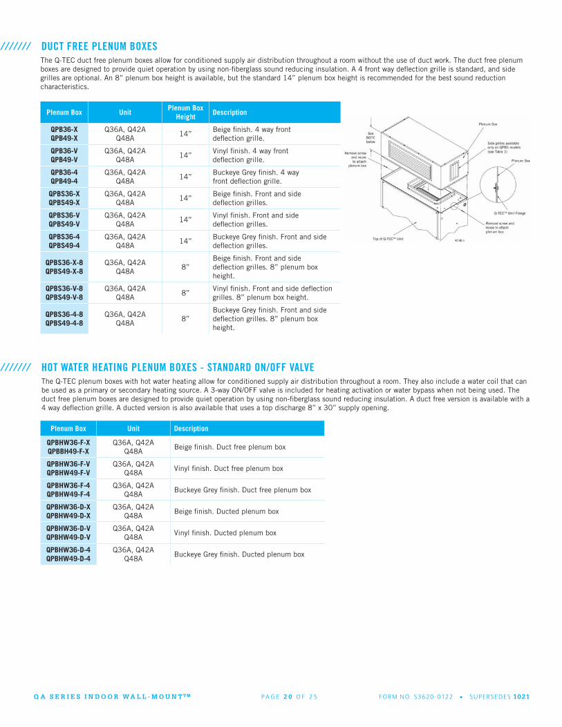
DUCT FREE PLENUM BOXES ///////
Plenum Box UnitPlenum Box
HeightDescription
QPB36-XQPB49-X
Q36A, Q42AQ48A
14”Beige finish. 4 way front deflection grille.
QPB36-VQPB49-V
Q36A, Q42AQ48A
14”Vinyl finish. 4 way front deflection grille.
QPB36-4QPB49-4
Q36A, Q42AQ48A
14”Buckeye Grey finish. 4 way front deflection grille.
QPBS36-XQPBS49-X
Q36A, Q42AQ48A
14”Beige finish. Front and side deflection grilles.
QPBS36-VQPBS49-V
Q36A, Q42AQ48A
14”Vinyl finish. Front and side deflection grilles.
QPBS36-4QPBS49-4
Q36A, Q42AQ48A
14”Buckeye Grey finish. Front and side deflection grilles.
QPBS36-X-8QPBS49-X-8
Q36A, Q42AQ48A
8”Beige finish. Front and side deflection grilles. 8” plenum box height.
QPBS36-V-8QPBS49-V-8
Q36A, Q42AQ48A
8”Vinyl finish. Front and side deflection grilles. 8” plenum box height.
QPBS36-4-8QPBS49-4-8
Q36A, Q42AQ48A
8”Buckeye Grey finish. Front and side deflection grilles. 8” plenum box height.
The Q-TEC duct free plenum boxes allow for conditioned supply air distribution throughout a room without the use of duct work. The duct free plenum boxes are designed to provide quiet operation by using non-fiberglass sound reducing insulation. A 4 front way deflection grille is standard, and side grilles are optional. An 8” plenum box height is available, but the standard 14” plenum box height is recommended for the best sound reduction characteristics.
HOT WATER HEATING PLENUM BOXES - STANDARD ON/OFF VALVE///////The Q-TEC plenum boxes with hot water heating allow for conditioned supply air distribution throughout a room. They also include a water coil that can be used as a primary or secondary heating source. A 3-way ON/OFF valve is included for heating activation or water bypass when not being used. The duct free plenum boxes are designed to provide quiet operation by using non-fiberglass sound reducing insulation. A duct free version is available with a 4 way deflection grille. A ducted version is also available that uses a top discharge 8” x 30” supply opening.
Plenum Box Unit Description
QPBHW36-F-XQPBBH49-F-X
Q36A, Q42AQ48A
Beige finish. Duct free plenum box
QPBHW36-F-VQPBHW49-F-V
Q36A, Q42AQ48A
Vinyl finish. Duct free plenum box
QPBHW36-F-4QPBHW49-F-4
Q36A, Q42AQ48A
Buckeye Grey finish. Duct free plenum box
QPBHW36-D-XQPBHW49-D-X
Q36A, Q42AQ48A
Beige finish. Ducted plenum box
QPBHW36-D-VQPBHW49-D-V
Q36A, Q42AQ48A
Vinyl finish. Ducted plenum box
QPBHW36-D-4QPBHW49-D-4
Q36A, Q42AQ48A
Buckeye Grey finish. Ducted plenum box
Q A S E R I E S I N D O O R W A L L - M O U N T T M P A G E 2 1 O F 2 5 FO R M N O. S362 0 - 0122 • S U P E R S E D E S 1021
Plenum Extension
UnitExtension
HeightDescription
Q4CX10A-XQ36AQ42A
10” + 5”Beige finish 10” height trim kit with 5” height extension angles.
Q4CX10A-VQ36AQ42A
10” + 5”Vinyl finish 10” height trim kit with 5” height extension angles.
Q4CX10A-4Q36AQ42A
10” + 5”Grey finish 10” height trim kit with 5” height extension angles.
Q4CX15A-X Q48A 10” + 5”Beige finish 10” height trim kit with 5” height extension angles.
Q4CX15A-V Q48A 10” + 5”Vinyl finish 10” height trim kit with 5” height extension angles.
Q4CX15A-4 Q48A 10” + 5”Grey finish 10” height trim kit with 5” height extension angles.
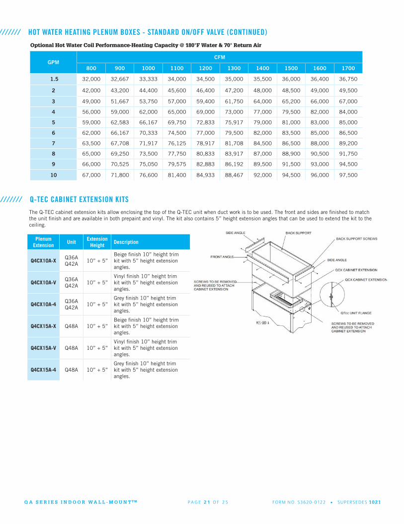
Q-TEC CABINET EXTENSION KITS///////The Q-TEC cabinet extension kits allow enclosing the top of the Q-TEC unit when duct work is to be used. The front and sides are finished to match the unit finish and are available in both prepaint and vinyl. The kit also contains 5” height extension angles that can be used to extend the kit to the ceiling.
Optional Hot Water Coil Performance-Heating Capacity @ 180°F Water & 70° Return Air
GPMCFM
800 900 1000 1100 1200 1300 1400 1500 1600 1700
1.5 32,000 32,667 33,333 34,000 34,500 35,000 35,500 36,000 36,400 36,750
2 42,000 43,200 44,400 45,600 46,400 47,200 48,000 48,500 49,000 49,500
3 49,000 51,667 53,750 57,000 59,400 61,750 64,000 65,200 66,000 67,000
4 56,000 59,000 62,000 65,000 69,000 73,000 77,000 79,500 82,000 84,000
5 59,000 62,583 66,167 69,750 72,833 75,917 79,000 81,000 83,000 85,000
6 62,000 66,167 70,333 74,500 77,000 79,500 82,000 83,500 85,000 86,500
7 63,500 67,708 71,917 76,125 78,917 81,708 84,500 86,500 88,000 89,200
8 65,000 69,250 73,500 77,750 80,833 83,917 87,000 88,900 90,500 91,750
9 66,000 70,525 75,050 79,575 82,883 86,192 89,500 91,500 93,000 94,500
10 67,000 71,800 76,600 81,400 84,933 88,467 92,000 94,500 96,000 97,500
HOT WATER HEATING PLENUM BOXES - STANDARD ON/OFF VALVE (CONTINUED)///////
Q A S E R I E S I N D O O R W A L L - M O U N T T M P A G E 2 2 O F 2 5 FO R M N O. S362 0 - 0122 • S U P E R S E D E S 1021
Extension Kit UnitExtension
HeightDescription
QPBX36-9-XQPBX49-9-X
Q36A, Q42AQ48A
14”Beige finish trim kit for 9’-6” ceiling heights.
QPBX36-9-VQPBX49-9-V
Q36A, Q42AQ48A
14”Vinyl finish trim kit for 9’-6” ceiling heights.
QPBX36-9-4QPBX49-9-4
Q36A, Q42AQ48A
14”Grey finish trim kit for 9’-6” ceiling heights.
QPBX36-10-XQPBX49-10-X
Q36A, Q42AQ48A
22”Beige finish trim kit for 10’-2” ceiling heights.
QPBX36-10-VQPBX49-10-V
Q36A, Q42AQ48A
22”Vinyl finish trim kit for 10’-2” ceiling heights.
QPBX36-10-4QPBX49-10-4
Q36A, Q42AQ48A
22”Grey finish trim kit for 10’-2” ceiling heights.
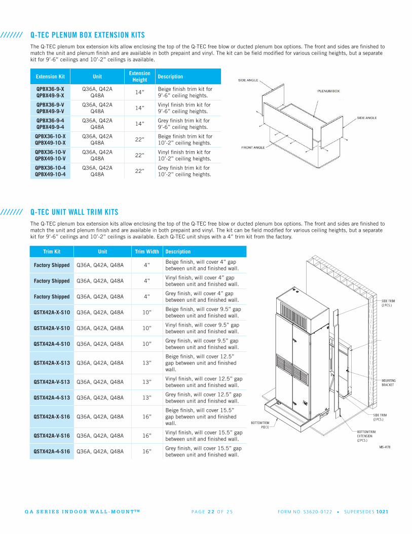
Q-TEC PLENUM BOX EXTENSION KITS///////The Q-TEC plenum box extension kits allow enclosing the top of the Q-TEC free blow or ducted plenum box options. The front and sides are finished to match the unit and plenum finish and are available in both prepaint and vinyl. The kit can be field modified for various ceiling heights, but a separate kit for 9’-6” ceilings and 10’-2” ceilings is available.
Trim Kit Unit Trim Width Description
Factory Shipped Q36A, Q42A, Q48A 4”Beige finish, will cover 4” gap between unit and finished wall.
Factory Shipped Q36A, Q42A, Q48A 4”Vinyl finish, will cover 4” gap between unit and finished wall.
Factory Shipped Q36A, Q42A, Q48A 4”Grey finish, will cover 4” gap between unit and finished wall.
QSTX42A-X-S10 Q36A, Q42A, Q48A 10”Beige finish, will cover 9.5” gap between unit and finished wall.
QSTX42A-V-S10 Q36A, Q42A, Q48A 10”Vinyl finish, will cover 9.5” gap between unit and finished wall.
QSTX42A-4-S10 Q36A, Q42A, Q48A 10”Grey finish, will cover 9.5” gap between unit and finished wall.
QSTX42A-X-S13 Q36A, Q42A, Q48A 13”Beige finish, will cover 12.5” gap between unit and finished wall.
QSTX42A-V-S13 Q36A, Q42A, Q48A 13”Vinyl finish, will cover 12.5” gap between unit and finished wall.
QSTX42A-4-S13 Q36A, Q42A, Q48A 13”Grey finish, will cover 12.5” gap between unit and finished wall.
QSTX42A-X-S16 Q36A, Q42A, Q48A 16”Beige finish, will cover 15.5” gap between unit and finished wall.
QSTX42A-V-S16 Q36A, Q42A, Q48A 16”Vinyl finish, will cover 15.5” gap between unit and finished wall.
QSTX42A-4-S16 Q36A, Q42A, Q48A 16”Grey finish, will cover 15.5” gap between unit and finished wall.
Q-TEC UNIT WALL TRIM KITS///////The Q-TEC plenum box extension kits allow enclosing the top of the Q-TEC free blow or ducted plenum box options. The front and sides are finished to match the unit and plenum finish and are available in both prepaint and vinyl. The kit can be field modified for various ceiling heights, but a separate kit for 9’-6” ceilings and 10’-2” ceilings is available. Each Q-TEC unit ships with a 4” trim kit from the factory.
MIS-4178
PIECEBOTTOM TRIM
MOUNTINGBRACKET
BOTTOM TRIMEXTENSION(2 PCS.)
SIDE TRIM(2 PCS.)
SIDE TRIM(2 PCS.)

Q A S E R I E S I N D O O R W A L L - M O U N T T M P A G E 2 3 O F 2 5 FO R M N O. S362 0 - 0122 • S U P E R S E D E S 1021
Q-TEC SOUND PLENUMS///////The Q-TEC sound plenum reduces sound of unit during operation offering an even quieter experience for the occupied space.
Sound Plenum Unit Width Finish
Q4SP3-X Q36A, Q42A 42” Beige
Q4SP3-V Q36A, Q42A 42” Vinyl
Q4SP3-4 Q36A, Q42A 42” Buckeye Grey
Q4SP5-X Q48A 48” Beige
Q4SP5-V Q48A 48” Vinyl
Q4SP5-4 Q48A 48” Buckeye Grey
THERMOSTAT, HUMIDISTAT AND CO2 VENTILATION CONTROL OPTIONS///////Bard provides a wide variety of controllers for equipment cooling, thermostats for equipment and comfort cooling, humidistats for dehumidification units, and CO2 sensors for ventilation control. Lockable thermostat covers are available for applications where security or supervisory control is desired.
Thermostat Operation Description
8403-060 3 Heat/3 Cool Programmable or Nonprogrammable, ventilation output, dehumidification operation.
8403-095 2 Heat/1 Cool Temp. Settings per Day 4, 2, 1, 0 Programs per Week 7, 5-2, 5-1-1 or Nonprogrammable.
8403-090 2 Heat/2 Cool Temp. Settings per Day 4, 2, 1, 0 Programs per Week 7, 5-2, 5-1-1 or Nonprogrammable.
8403-092 2 Heat/2 Cool Programmable or Nonprogrammable, ventilation output, Wi-Fi
Humidistat Operation Description
8403-038 Humidity %RH Easy to use w/SPDT switching. Ratings: Pilot duty 50VA @24V, 120VA @120/240V
8403-047 Humidity %RH Electronic with display, EEPROM memory, lockable keypad, humidity sensor calibration.
CO2 Operation Description
8403-096 CO2 PPM CO2 cventilation control with digital display. On/Off or modulating ventilation operation.
ThermostatCover*
Size Description
8405-003(Inside) 5-1/16” H x 6-1/16” W,(Outside) 6-1/2” H x 7-1/2” W x 2-15/16” D
Clear acrylic ventilation. Fits all thermostats except 8403-060.
8405-005(Inside) 5-7/8” H x 8-3/8” W,(Outside) 7-1/4” H x 9-3/4” W x 3-3/8” D
Clear acrylic with ventilation. Fits all thermostats.
8405-006(Inside) 5-1/16” H x 6-1/16” W,(Outside) 6-3/8” H x 7-3/8” W x 2-7/8” D
Beige painted steel cover with ventilation. Fits all thermostats except 8403-060.
8405-007(Inside) 5-7/8” H x 8-3/8” W,(Outside) 7-1/8” H x 9-5/8” W x 3-1/4” D
Beige painted steel cover with ventilation. Fits all thermostats.
* Thermostat covers include ventilation, but may affect temperature control reaction time. If security control lockout is needed, the 8403-060 thermostat provides input control lockout features.
MIS-4324
Q A S E R I E S I N D O O R W A L L - M O U N T T M P A G E 2 4 O F 2 5 FO R M N O. S362 0 - 0122 • S U P E R S E D E S 1021
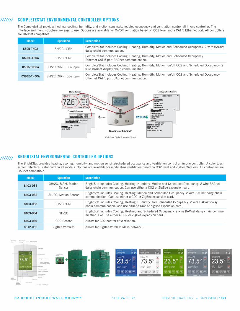
COMPLETESTAT ENVIRONMENTAL CONTROLLER OPTIONS///////The CompleteStat provides heating, cooling, humidity, and motion sensing/scheduled occupancy and ventilation control all in one controller. The interface and menu structure are easy to use. Options are available for On/Off ventilation based on CO2 level and a CAT 5 Ethernet port. All controllers are BACnet compatible.
Model Operation Description
CS9B-THOA 3H/2C, %RHCompleteStat includes Cooling, Heating, Humidity, Motion and Scheduled Occupancy. 2 wire BACnet daisy chain communication.
CS9BE-THOA 3H/2C, %RHCompleteStat includes Cooling, Heating, Humidity, Motion and Scheduled Occupancy.Ethernet CAT 5 port BACnet communication.
CS9B-THOCA 3H/2C, %RH, CO2 ppm.CompleteStat includes Cooling, Heating, Humidity, Motion, on/off CO2 and Scheduled Occupancy. 2 wire BACnet display chain communication.
CS9BE-THOCA 3H/2C, %RH, CO2 ppm.CompleteStat includes Cooling, Heating, Humidity, Motion, on/off CO2 and Scheduled Occupancy. Ethernet CAT 5 port BACnet communication.
BRIGHTSTAT ENVIRONMENTAL CONTROLLER OPTIONS///////The BrightStat provides heating, cooling, humidity, and motion sensing/scheduled occupancy and ventilation control all in one controller. A color touch screen interface is standard on all models. Options are available for modulating ventilation based on CO2 level and ZigBee Wireless. All controllers are BACnet compatible.
Model Operation Description
8403-0813H/2C, %RH, Motion
SensorBrightStat includes Cooling, Heating, Humidity, Motion and Scheduled Occupancy. 2 wire BACnet daisy chain communication. Can use either a CO2 or ZigBee expansion card.
8403-082 3H/2C, Motion SensorBrightStat includes Cooling, Heating, Motion and Scheduled Occupancy. 2 wire BACnet daisy chain communication. Can use either a CO2 or ZigBee expansion card.
8403-083 3H/2C, %RHBrightStat includes Cooling, Heating, Humidity, and Scheduled Occupancy. 2 wire BACnet daisy chain communication. Can use either a CO2 or ZigBee expansion card.
8403-084 3H/2CBrightStat includes Cooling, Heating, and Scheduled Occupancy. 2 wire BACnet daisy chain commu-nication. Can use either a CO2 or ZigBee expansion card.
8403-086 CO2 Sensor Allows for CO2 control of ventilation.
8612-052 ZigBee Wireless Allows for ZigBee Wireless Mesh network.

Q A S E R I E S I N D O O R W A L L - M O U N T T M P A G E 2 5 O F 2 5 FO R M N O. S362 0 - 0122 • S U P E R S E D E S 1021
Due to our continuous product improvement policy, all specifications subject to change without notice. Before purchasing this appliance, read important energy cost and efficiency information available from your retailer.
Bard Manufacturing Company, Inc.1914 Randolph Dr., Bryan, OH 43506419-636-1194
www.bardhvac.com