1.1about the documentation - daikin
TRANSCRIPT
Installer reference guideDaikin room air conditioner English
Installer reference guide
Daikin room air conditioner
FTXP20L2V1BFTXP25L2V1BFTXP35L2V1B
ATXP20L2V1BATXP25L2V1BATXP35L2V1B
FTXF20A2V1BFTXF25A2V1BFTXF35A2V1BFTXF50A2V1BFTXF60A2V1BFTXF71A2V1B
Table of Contents
Installer reference guide
2(A)(F)TXP20~35L2V1B + FTXF20~71A2V1B
Daikin room air conditioner4P513661-1 – 2017.10
Table of Contents
1 General safety precautions 21.1 About the documentation .......................................................... 2
1.1.1 Meaning of warnings and symbols.............................. 21.2 For the installer.......................................................................... 3
1.2.1 General ....................................................................... 31.2.2 Installation site ............................................................ 31.2.3 Refrigerant .................................................................. 51.2.4 Brine............................................................................ 51.2.5 Water .......................................................................... 51.2.6 Electrical ..................................................................... 6
2 About the documentation 62.1 About this document.................................................................. 62.2 Installer reference guide at a glance ......................................... 7
3 About the box 73.1 Overview: About the box ........................................................... 73.2 Indoor unit ................................................................................. 7
3.2.1 To unpack the indoor unit ........................................... 73.2.2 To remove the accessories from the indoor unit......... 7
4 About the units 84.1 System layout............................................................................ 84.2 Operation range ........................................................................ 8
5 Preparation 85.1 Overview: Preparation............................................................... 85.2 Preparing the installation site .................................................... 8
5.2.1 Installation site requirements of the indoor unit .......... 85.3 Preparing refrigerant piping....................................................... 9
5.3.1 Refrigerant piping requirements.................................. 95.3.2 Refrigerant piping insulation ....................................... 9
5.4 Preparing electrical wiring ......................................................... 95.4.1 About preparing electrical wiring................................. 9
6 Installation 106.1 Overview: Installation ................................................................ 106.2 Mounting the indoor unit ............................................................ 10
6.2.1 Precautions when mounting the indoor unit................ 106.2.2 To open the indoor unit ............................................... 106.2.3 To install the mounting plate ....................................... 116.2.4 To install the indoor unit.............................................. 126.2.5 To provide drainage .................................................... 136.2.6 To connect optional accessories (wired user
interface, central user interface, wireless adapter,etc.) ............................................................................. 14
6.2.7 To install the wireless adapter .................................... 146.2.8 To set a different address ........................................... 15
6.3 Connecting the refrigerant piping .............................................. 156.3.1 About connecting the refrigerant piping ...................... 156.3.2 Precautions when connecting the refrigerant piping ... 156.3.3 Guidelines when connecting the refrigerant piping ..... 166.3.4 Pipe bending guidelines.............................................. 166.3.5 To flare the pipe end ................................................... 166.3.6 To connect the refrigerant piping to the indoor unit .... 17
6.4 Connecting the electrical wiring................................................. 176.4.1 About connecting the electrical wiring......................... 176.4.2 Precautions when connecting the electrical wiring ..... 176.4.3 Guidelines when connecting the electrical wiring ....... 176.4.4 Specifications of standard wiring components............ 176.4.5 To connect the electrical wiring on the indoor unit...... 18
7 Commissioning 187.1 Overview: Commissioning......................................................... 187.2 Checklist before commissioning................................................ 187.3 To perform a test run................................................................. 18
7.3.1 To perform a test run in winter season ....................... 18
8 Hand-over to the user 19
9 Disposal 19
10 Technical data 2010.1 Wiring diagram ........................................................................... 20
11 Glossary 21
1 General safety precautions
1.1 About the documentation▪ The original documentation is written in English. All other
languages are translations.
▪ The precautions described in this document cover very importanttopics, follow them carefully.
▪ The installation of the system, and all activities described in theinstallation manual and the installer reference guide MUST beperformed by an authorised installer.
1.1.1 Meaning of warnings and symbols
DANGER
Indicates a situation that results in death or serious injury.
DANGER: RISK OF ELECTROCUTION
Indicates a situation that could result in electrocution.
DANGER: RISK OF BURNING
Indicates a situation that could result in burning because ofextreme hot or cold temperatures.
DANGER: RISK OF EXPLOSION
Indicates a situation that could result in explosion.
WARNING
Indicates a situation that could result in death or seriousinjury.
WARNING: FLAMMABLE MATERIAL
CAUTION
Indicates a situation that could result in minor or moderateinjury.
NOTICE
Indicates a situation that could result in equipment orproperty damage.
INFORMATION
Indicates useful tips or additional information.
Symbol ExplanationBefore installation, read the installation andoperation manual, and the wiring instruction sheet.
Before performing maintenance and service tasks,read the service manual.For more information, see the installer and userreference guide.
1 General safety precautions
Installer reference guide
3(A)(F)TXP20~35L2V1B + FTXF20~71A2V1BDaikin room air conditioner4P513661-1 – 2017.10
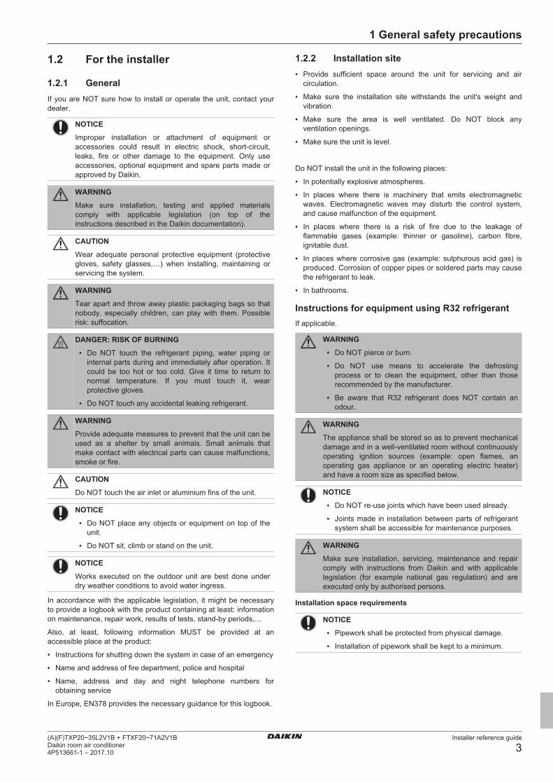
1.2 For the installer
1.2.1 GeneralIf you are NOT sure how to install or operate the unit, contact yourdealer.
NOTICE
Improper installation or attachment of equipment oraccessories could result in electric shock, short-circuit,leaks, fire or other damage to the equipment. Only useaccessories, optional equipment and spare parts made orapproved by Daikin.
WARNING
Make sure installation, testing and applied materialscomply with applicable legislation (on top of theinstructions described in the Daikin documentation).
CAUTION
Wear adequate personal protective equipment (protectivegloves, safety glasses,…) when installing, maintaining orservicing the system.
WARNING
Tear apart and throw away plastic packaging bags so thatnobody, especially children, can play with them. Possiblerisk: suffocation.
DANGER: RISK OF BURNING
▪ Do NOT touch the refrigerant piping, water piping orinternal parts during and immediately after operation. Itcould be too hot or too cold. Give it time to return tonormal temperature. If you must touch it, wearprotective gloves.
▪ Do NOT touch any accidental leaking refrigerant.
WARNING
Provide adequate measures to prevent that the unit can beused as a shelter by small animals. Small animals thatmake contact with electrical parts can cause malfunctions,smoke or fire.
CAUTION
Do NOT touch the air inlet or aluminium fins of the unit.
NOTICE
▪ Do NOT place any objects or equipment on top of theunit.
▪ Do NOT sit, climb or stand on the unit.
NOTICE
Works executed on the outdoor unit are best done underdry weather conditions to avoid water ingress.
In accordance with the applicable legislation, it might be necessaryto provide a logbook with the product containing at least: informationon maintenance, repair work, results of tests, stand-by periods,…
Also, at least, following information MUST be provided at anaccessible place at the product:
▪ Instructions for shutting down the system in case of an emergency
▪ Name and address of fire department, police and hospital
▪ Name, address and day and night telephone numbers forobtaining service
In Europe, EN378 provides the necessary guidance for this logbook.
1.2.2 Installation site▪ Provide sufficient space around the unit for servicing and air
circulation.
▪ Make sure the installation site withstands the unit's weight andvibration.
▪ Make sure the area is well ventilated. Do NOT block anyventilation openings.
▪ Make sure the unit is level.
Do NOT install the unit in the following places:
▪ In potentially explosive atmospheres.
▪ In places where there is machinery that emits electromagneticwaves. Electromagnetic waves may disturb the control system,and cause malfunction of the equipment.
▪ In places where there is a risk of fire due to the leakage offlammable gases (example: thinner or gasoline), carbon fibre,ignitable dust.
▪ In places where corrosive gas (example: sulphurous acid gas) isproduced. Corrosion of copper pipes or soldered parts may causethe refrigerant to leak.
▪ In bathrooms.
Instructions for equipment using R32 refrigerantIf applicable.
WARNING
▪ Do NOT pierce or burn.
▪ Do NOT use means to accelerate the defrostingprocess or to clean the equipment, other than thoserecommended by the manufacturer.
▪ Be aware that R32 refrigerant does NOT contain anodour.
WARNING
The appliance shall be stored so as to prevent mechanicaldamage and in a well-ventilated room without continuouslyoperating ignition sources (example: open flames, anoperating gas appliance or an operating electric heater)and have a room size as specified below.
NOTICE
▪ Do NOT re-use joints which have been used already.
▪ Joints made in installation between parts of refrigerantsystem shall be accessible for maintenance purposes.
WARNING
Make sure installation, servicing, maintenance and repaircomply with instructions from Daikin and with applicablelegislation (for example national gas regulation) and areexecuted only by authorised persons.
Installation space requirements
NOTICE
▪ Pipework shall be protected from physical damage.
▪ Installation of pipework shall be kept to a minimum.
1 General safety precautions
Installer reference guide
4(A)(F)TXP20~35L2V1B + FTXF20~71A2V1B
Daikin room air conditioner4P513661-1 – 2017.10
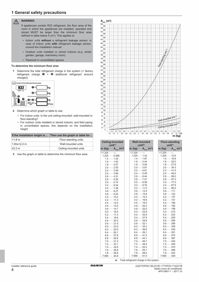
WARNING
If appliances contain R32 refrigerant, the floor area of theroom in which the appliances are installed, operated andstored MUST be larger than the minimum floor areadefined in table below A (m2). This applies to:
▪ Indoor units without a refrigerant leakage sensor; incase of indoor units with refrigerant leakage sensor,consult the installation manual
▪ Outdoor units installed or stored indoors (e.g. wintergarden, garage, machinery room)
▪ Pipework in unventilated spaces
To determine the minimum floor area
1 Determine the total refrigerant charge in the system (= factoryrefrigerant charge + additional refrigerant amountcharged).
Contains fluorinated greenhouse gases
21 1
1
2
2 kgtCO2eq1000
GWP × kg==
+
kg=
kg=GWP: xxxR32
2 Determine which graph or table to use.
▪ For indoor units: Is the unit ceiling-mounted, wall-mounted orfloor-standing?
▪ For outdoor units installed or stored indoors, and field pipingin unventilated spaces, this depends on the installationheight:
If the installation height is… Then use the graph or table for…<1.8 m Floor-standing units1.8≤x<2.2 m Wall-mounted units≥2.2 m Ceiling-mounted units
3 Use the graph or table to determine the minimum floor area.
m (kg)
010
2030
4050
6070
8090
100110
120130
140150
160170
180190
200210
220230
240250
260270
280290
300310
320330
340350
360370
380390
400410
420430
440450
460470
480490
500510
520530
540550
11.2
1.41.6
1.82
2.22.4
2.62.8
33.2
3.43.6
3.84
4.24.4
4.64.8
55.2
5.45.6
5.86
6.26.4
6.66.8
77.2
7.47.6
7.87.956
Amin (m2)
Floor-
stand
ing un
it (c)
Wall-mounted unit (b)
Ceiling-mounted unit (a)
Ceiling-mountedunit(a)
—
4.6 13.5
<1.224 <1.224 —
4.6 182
1.225 0.956
4.8 14.7
1.225 12.9
4.8 198
1.4 1.25
5.0 16.0
1.4 16.8
5.0 215
1.6 1.63
5.2 17.3
1.6 22.0
5.2 232
1.8 2.07
5.4 18.6
1.8 27.8
5.4 250
2.0 2.55
5.6 20.0
2.0 34.3
5.6 269
2.2 3.09
5.8 21.5
2.2 41.5
5.8 289
2.4 3.68
6.0 23.0
2.4 49.4
6.0 309
2.6 4.31
6.2 24.5
2.6 58.0
6.2 330
2.8 5.00
6.4 26.1
2.8 67.3
6.4 351
3.0 5.74
6.6 27.8
3.0 77.2
6.6 374
3.2 6.54
6.8 29.5
3.2 87.9
6.8 397
3.4 7.38
7.0 31.3
3.4 99.2
7.0 420
3.6 8.27
7.2 33.1
3.6 111
7.2 445
3.8 9.22
7.4 34.9
3.8 124
7.4 470
4.0 10.2
7.6 36.9
4.0 137
7.6 496
4.2 11.3
7.8 38.8
4.2 151
7.8 522
4.4 12.4
7.956 40.8
4.4 166
7.956 549
m (kg) Amin (m2)<1.224 —
4.6 20.2
1.225 1.43
4.8 22.0
1.4 1.87
5.0 23.8
1.6 2.44
5.2 25.8
1.8 3.09
5.4 27.8
2.0 3.81
5.6 29.9
2.2 4.61
5.8 32.1
2.4 5.49
6.0 34.3
2.6 6.44
6.2 36.6
2.8 7.47
6.4 39.1
3.0 8.58
6.6 41.5
3.2 9.76
6.8 44.1
3.4 11.0
7.0 46.7
3.6 12.4
7.2 49.4
3.8 13.8
7.4 52.2
4.0 15.3
7.6 55.1
4.2 16.8
7.8 58.0
4.4 18.5
7.956 61.0
Wall-mountedunit(b)
m (kg) Amin (m2)
Floor-standingunit(c)
m (kg) Amin (m2)
m Total refrigerant charge in the system

1 General safety precautions
Installer reference guide
5(A)(F)TXP20~35L2V1B + FTXF20~71A2V1BDaikin room air conditioner4P513661-1 – 2017.10
Amin Minimum floor area(a) Ceiling-mounted unit (= Ceiling-mounted unit)(b) Wall-mounted unit (= Wall-mounted unit)(c) Floor-standing unit (= Floor-standing unit)
1.2.3 RefrigerantIf applicable. See the installation manual or installer reference guideof your application for more information.
NOTICE
Make sure refrigerant piping installation complies withapplicable legislation. In Europe, EN378 is the applicablestandard.
NOTICE
Make sure the field piping and connections are NOTsubjected to stress.
WARNING
During tests, NEVER pressurize the product with apressure higher than the maximum allowable pressure (asindicated on the nameplate of the unit).
WARNING
Take sufficient precautions in case of refrigerant leakage. Ifrefrigerant gas leaks, ventilate the area immediately.Possible risks:
▪ Excessive refrigerant concentrations in a closed roomcan lead to oxygen deficiency.
▪ Toxic gas may be produced if refrigerant gas comesinto contact with fire.
DANGER: RISK OF EXPLOSION
Pump down – Refrigerant leakage. If you want to pumpdown the system, and there is a leakage in the refrigerantcircuit:
▪ Do NOT use the unit's automatic pump down function,with which you can collect all refrigerant from thesystem into the outdoor unit. Possible consequence:Self-combustion and explosion of the compressorbecause of air going into the operating compressor.
▪ Use a separate recovery system so that the unit'scompressor does NOT have to operate.
WARNING
ALWAYS recover the refrigerant. Do NOT release themdirectly into the environment. Use a vacuum pump toevacuate the installation.
NOTICE
After all the piping has been connected, make sure there isno gas leak. Use nitrogen to perform a gas leak detection.
NOTICE
▪ To avoid compressor breakdown, do NOT charge morethan the specified amount of refrigerant.
▪ When the refrigerant system is to be opened,refrigerant MUST be treated according to the applicablelegislation.
WARNING
Make sure there is no oxygen in the system. Refrigerantmay only be charged after performing the leak test and thevacuum drying.
▪ In case re-charge is required, refer to the nameplate of the unit. Itstates the type of refrigerant and necessary amount.
▪ The unit is factory charged with refrigerant and depending on pipesizes and pipe lengths some systems require additional chargingof refrigerant.
▪ Only use tools exclusively for the refrigerant type used in thesystem, this to ensure pressure resistance and prevent foreignmaterials from entering into the system.
▪ Charge the liquid refrigerant as follows:
If ThenA siphon tube is present
(i.e., the cylinder is marked with"Liquid filling siphon attached")
Charge with the cylinder upright.
A siphon tube is NOT present Charge with the cylinder upsidedown.
▪ Open refrigerant cylinders slowly.
▪ Charge the refrigerant in liquid form. Adding it in gas form mayprevent normal operation.
CAUTION
When the refrigerant charging procedure is done or whenpausing, close the valve of the refrigerant tankimmediately. If the valve is NOT closed immediately,remaining pressure might charge additional refrigerant.Possible consequence: Incorrect refrigerant amount.
1.2.4 BrineIf applicable. See the installation manual or installer reference guideof your application for more information.
WARNING
The selection of the brine MUST be in accordance with theapplicable legislation.
WARNING
Take sufficient precautions in case of brine leakage. Ifbrine leaks, ventilate the area immediately and contactyour local dealer.
WARNING
The ambient temperature inside the unit can get muchhigher than that of the room, e.g. 70°C. In case of a brineleak, hot parts inside the unit can create a hazardoussituation.
WARNING
The use and installation of the application MUST complywith the safety and environmental precautions specified inthe applicable legislation.
1.2.5 WaterIf applicable. See the installation manual or installer reference guideof your application for more information.
NOTICE
Make sure water quality complies with EU directive98/83 EC.

2 About the documentation
Installer reference guide
6(A)(F)TXP20~35L2V1B + FTXF20~71A2V1B
Daikin room air conditioner4P513661-1 – 2017.10
1.2.6 Electrical
DANGER: RISK OF ELECTROCUTION
▪ Turn OFF all power supply before removing theswitch box cover, connecting electrical wiring ortouching electrical parts.
▪ Disconnect the power supply for more than 1 minute,and measure the voltage at the terminals of main circuitcapacitors or electrical components before servicing.The voltage MUST be less than 50 V DC before youcan touch electrical components. For the location of theterminals, see the wiring diagram.
▪ Do NOT touch electrical components with wet hands.
▪ Do NOT leave the unit unattended when the servicecover is removed.
WARNING
If NOT factory installed, a main switch or other means fordisconnection, having a contact separation in all polesproviding full disconnection under overvoltage category IIIcondition, MUST be installed in the fixed wiring.
WARNING
▪ ONLY use copper wires.
▪ Make sure the field wiring complies with the applicablelegislation.
▪ All field wiring MUST be performed in accordance withthe wiring diagram supplied with the product.
▪ NEVER squeeze bundled cables and make sure theydo NOT come in contact with the piping and sharpedges. Make sure no external pressure is applied to theterminal connections.
▪ Make sure to install earth wiring. Do NOT earth the unitto a utility pipe, surge absorber, or telephone earth.Incomplete earth may cause electrical shock.
▪ Make sure to use a dedicated power circuit. NEVERuse a power supply shared by another appliance.
▪ Make sure to install the required fuses or circuitbreakers.
▪ Make sure to install an earth leakage protector. Failureto do so may cause electric shock or fire.
▪ When installing the earth leakage protector, make sureit is compatible with the inverter (resistant to highfrequency electric noise) to avoid unnecessary openingof the earth leakage protector.
NOTICE
Precautions when laying power wiring:
▪ Do NOT connect wiring of different thicknesses to thepower terminal block (slack in the power wiring maycause abnormal heat).
▪ When connecting wiring which is the same thickness,do as shown in the figure above.
▪ For wiring, use the designated power wire and connectfirmly, then secure to prevent outside pressure beingexerted on the terminal board.
▪ Use an appropriate screwdriver for tightening theterminal screws. A screwdriver with a small head willdamage the head and make proper tighteningimpossible.
▪ Over-tightening the terminal screws may break them.
WARNING
▪ After finishing the electrical work, confirm that eachelectrical component and terminal inside the electricalcomponents box is connected securely.
▪ Make sure all covers are closed before starting up theunit.
NOTICE
Only applicable if the power supply is three‑phase, and thecompressor has an ON/OFF starting method.
If there exists the possibility of reversed phase after amomentary black out and the power goes on and off whilethe product is operating, attach a reversed phaseprotection circuit locally. Running the product in reversedphase can break the compressor and other parts.
2 About the documentation
2.1 About this documentINFORMATION
Make sure that the user has the printed documentation andask him/her to keep it for future reference.
Target audienceAuthorised installers
INFORMATION
This appliance is intended to be used by expert or trainedusers in shops, in light industry, and on farms, or forcommercial and household use by lay persons.
Documentation setThis document is part of a documentation set. The complete setconsists of:
▪ General safety precautions:
▪ Safety instructions that you MUST read before installing
▪ Format: Paper (in the box of the indoor unit)
▪ Indoor unit installation manual:
▪ Installation instructions
▪ Format: Paper (in the box of the indoor unit)
3 About the box
Installer reference guide
7(A)(F)TXP20~35L2V1B + FTXF20~71A2V1BDaikin room air conditioner4P513661-1 – 2017.10
▪ Installer reference guide:
▪ Preparation of the installation, good practices, reference data,…
▪ Format: Digital files on http://www.daikineurope.com/support-and-manuals/product-information/
Latest revisions of the supplied documentation may be available onthe regional Daikin website or via your dealer.
The original documentation is written in English. All other languagesare translations.
Technical engineering data▪ A subset of the latest technical data is available on the regional
Daikin website (publicly accessible).
▪ The full set of latest technical data is available on the Daikinextranet (authentication required).
2.2 Installer reference guide at aglance
Chapter DescriptionGeneral safetyprecautions
Safety instructions that you MUST readbefore installing
About the documentation What documentation exists for theinstaller
About the box How to unpack the units and removetheir accessories
About the unit ▪ How to identify the units
▪ Operation rangePreparation What to do and know before going
on‑siteInstallation What to do and know to install the
systemCommissioning What to do and know to commission the
system after it is configuredHand‑over to the user What to give and explain to the userDisposal How to dispose of the systemTechnical data Specifications of the systemGlossary Definition of terms
3 About the box
3.1 Overview: About the boxThis chapter describes what you have to do after the box with theindoor unit is delivered on-site.
It contains information about:
▪ Unpacking and handling the units
▪ Removing the accessories from the units
Keep the following in mind:
▪ At delivery, the unit MUST be checked for damage. Any damageMUST be reported immediately to the carrier's claims agent.
▪ Bring the packed unit as close as possible to its final installationposition to prevent damage during transport.
▪ When handling the unit, take into account the following:
Fragile, handle the unit with care.
Keep the unit upright in order to avoid damage.
▪ Prepare the path along which you want to bring the unit inside inadvance.
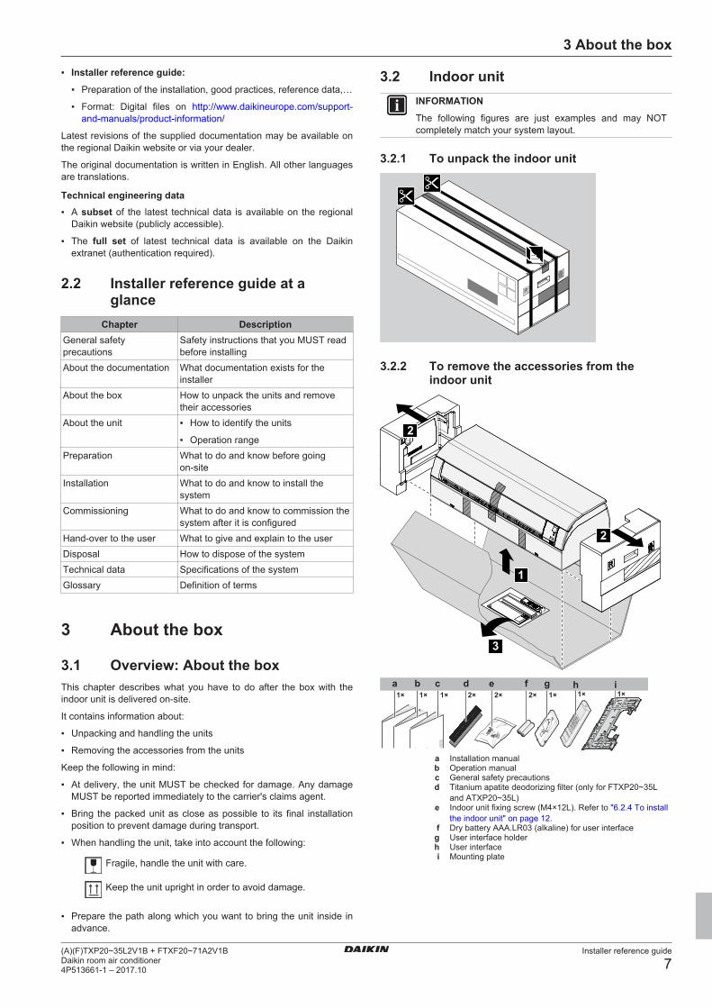
3.2 Indoor unitINFORMATION
The following figures are just examples and may NOTcompletely match your system layout.
3.2.1 To unpack the indoor unit
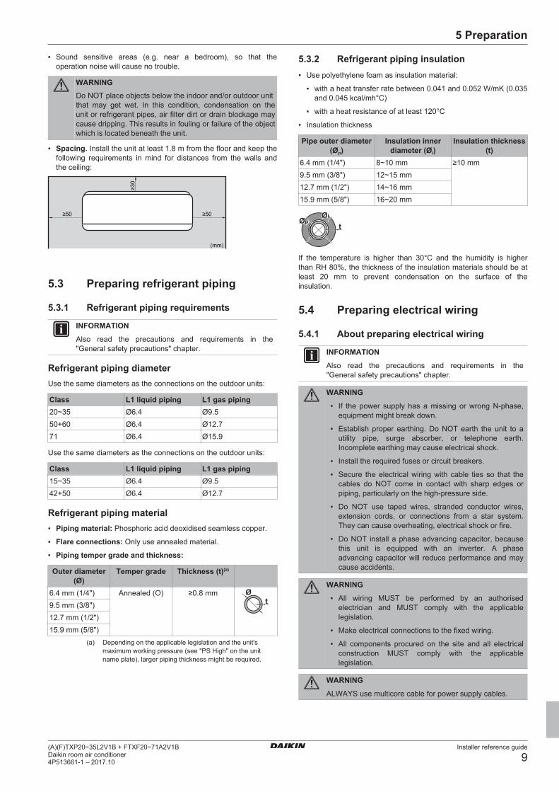
3.2.2 To remove the accessories from theindoor unit
1
3
2
2
2× 2× 2×1× 1× 1×1× 1× 1×edba c f g h i
a Installation manualb Operation manualc General safety precautionsd Titanium apatite deodorizing filter (only for FTXP20~35L
and ATXP20~35L)e Indoor unit fixing screw (M4×12L). Refer to "6.2.4 To install
the indoor unit" on page 12.f Dry battery AAA.LR03 (alkaline) for user interfaceg User interface holderh User interfacei Mounting plate

4 About the units
Installer reference guide
8(A)(F)TXP20~35L2V1B + FTXF20~71A2V1B
Daikin room air conditioner4P513661-1 – 2017.10
4 About the units
4.1 System layoutNOTICE
Design of the system must not be done at temperaturesbelow –15°C.
d
a
f
ce
b
a Indoor unitb Service lidc Air filterd Titanium apatite deodorizing filter (only for ATXP-L and
FTXP-L)e Refrigerant piping, drain hose and interconnection cablef Insulation tape
4.2 Operation rangeUse the system in the following temperature and humidity ranges forsafe and effective operation.
Operation mode Operation rangeCooling(a)(b) ▪ Outdoor temperature: –10~46°C
▪ Indoor temperature: 18~32°C
▪ Indoor humidity: ≤80%Heating(a) ▪ Outdoor temperature: –15~24°C
▪ Indoor temperature: 10~30°CDrying(a) ▪ Outdoor temperature: –10~46°C
▪ Indoor temperature: 18~32°C
▪ Indoor humidity: ≤80%If operated outside the operation range:
(a) A safety device might stop the operation of the system.(b) Condensation might occur on the indoor unit and drip.
5 Preparation
5.1 Overview: PreparationThis chapter describes what you have to do and know before goingon-site.
It contains information about:
▪ Preparing the installation site
▪ Preparing the refrigerant piping
▪ Preparing the electrical wiring
5.2 Preparing the installation siteDo NOT install the unit in places often used as work place. In caseof construction works (e.g. grinding works) where a lot of dust iscreated, the unit MUST be covered.
Choose an installation location with sufficient space for carrying theunit in and out of the site.
WARNING
The appliance shall be stored in a room withoutcontinuously operating ignition sources (example: openflames, an operating gas appliance or an operating electricheater).
5.2.1 Installation site requirements of theindoor unit
INFORMATION
Also read the precautions and requirements in the"General safety precautions" chapter.
INFORMATION
The sound pressure level is less than 70 dBA.
▪ Air flow. Make sure nothing blocks the air flow.
▪ Drainage. Make sure condensation water can be evacuatedproperly.
▪ Wall insulation. When conditions in the wall exceed 30°C and arelative humidity of 80%, or when fresh air is inducted into thewall, then additional insulation is required (minimum 10 mmthickness, polyethylene foam).
▪ Wall strength. Check whether the wall or the floor is strongenough to support the weight of the unit. If there is a risk, reinforcethe wall or the floor before installing the unit.
Install power cables at least 1 metre away from televisions or radiosto prevent interference. Depending on the radio waves, a distance of3 metres may NOT be sufficient.
▪ Choose a location where the hot/cold air discharged from the unitor the operation noise, will NOT disturb anyone.
▪ Fluorescent lights. When installing a wireless user interface in aroom with fluorescent lights, mind the following to avoidinterference:
▪ Install the wireless user interface as close as possible to theindoor unit.
▪ Install the indoor unit as far as possible from the fluorescentlights.
▪ In places where a mineral oil mist, spray or vapour may bepresent in the atmosphere. Plastic parts may deteriorate and falloff or cause water leakage.
It is NOT recommended to install the unit in the following placesbecause it may shorten the life of the unit:
▪ Where the voltage fluctuates a lot
▪ In vehicles or vessels
▪ Where acidic or alkaline vapour is present
▪ In places where a mineral oil mist, spray or vapour may bepresent in the atmosphere. Plastic parts may deteriorate and falloff or cause water leakage.
▪ In places where the unit would be in the path of direct sunlight.
▪ In bathrooms.
5 Preparation
Installer reference guide
9(A)(F)TXP20~35L2V1B + FTXF20~71A2V1BDaikin room air conditioner4P513661-1 – 2017.10
▪ Sound sensitive areas (e.g. near a bedroom), so that theoperation noise will cause no trouble.
WARNINGDo NOT place objects below the indoor and/or outdoor unit that may get wet. In this condition, condensation on the unit or refrigerant pipes, air filter dirt or drain blockage may cause dripping. This results in fouling or failure of the object which is located beneath the unit.
▪ Spacing. Install the unit at least 1.8 m from the floor and keep thefollowing requirements in mind for distances from the walls andthe ceiling:
≥50 ≥50
≥30
(mm)
5.3 Preparing refrigerant piping
5.3.1 Refrigerant piping requirements
INFORMATION
Also read the precautions and requirements in the"General safety precautions" chapter.
Refrigerant piping diameterUse the same diameters as the connections on the outdoor units:
Class L1 liquid piping L1 gas piping20~35 Ø6.4 Ø9.550+60 Ø6.4 Ø12.771 Ø6.4 Ø15.9
Use the same diameters as the connections on the outdoor units:
Class L1 liquid piping L1 gas piping15~35 Ø6.4 Ø9.542+50 Ø6.4 Ø12.7
Refrigerant piping material▪ Piping material: Phosphoric acid deoxidised seamless copper.
▪ Flare connections: Only use annealed material.
▪ Piping temper grade and thickness:
Outer diameter(Ø)
Temper grade Thickness (t)(a)
6.4 mm (1/4") Annealed (O) ≥0.8 mmt
Ø
9.5 mm (3/8")12.7 mm (1/2")15.9 mm (5/8")
(a) Depending on the applicable legislation and the unit'smaximum working pressure (see "PS High" on the unitname plate), larger piping thickness might be required.
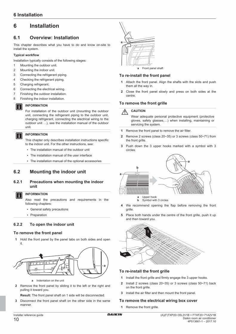
5.3.2 Refrigerant piping insulation▪ Use polyethylene foam as insulation material:
▪ with a heat transfer rate between 0.041 and 0.052 W/mK (0.035and 0.045 kcal/mh°C)
▪ with a heat resistance of at least 120°C
▪ Insulation thickness
Pipe outer diameter(Øp)
Insulation innerdiameter (Øi)
Insulation thickness(t)
6.4 mm (1/4") 8~10 mm ≥10 mm9.5 mm (3/8") 12~15 mm12.7 mm (1/2") 14~16 mm15.9 mm (5/8") 16~20 mm
ØiØi
tØpØp
If the temperature is higher than 30°C and the humidity is higherthan RH 80%, the thickness of the insulation materials should be atleast 20 mm to prevent condensation on the surface of theinsulation.
5.4 Preparing electrical wiring
5.4.1 About preparing electrical wiring
INFORMATION
Also read the precautions and requirements in the"General safety precautions" chapter.
WARNING
▪ If the power supply has a missing or wrong N-phase,equipment might break down.
▪ Establish proper earthing. Do NOT earth the unit to autility pipe, surge absorber, or telephone earth.Incomplete earthing may cause electrical shock.
▪ Install the required fuses or circuit breakers.
▪ Secure the electrical wiring with cable ties so that thecables do NOT come in contact with sharp edges orpiping, particularly on the high-pressure side.
▪ Do NOT use taped wires, stranded conductor wires,extension cords, or connections from a star system.They can cause overheating, electrical shock or fire.
▪ Do NOT install a phase advancing capacitor, becausethis unit is equipped with an inverter. A phaseadvancing capacitor will reduce performance and maycause accidents.
WARNING
▪ All wiring MUST be performed by an authorisedelectrician and MUST comply with the applicablelegislation.
▪ Make electrical connections to the fixed wiring.
▪ All components procured on the site and all electricalconstruction MUST comply with the applicablelegislation.
WARNING
ALWAYS use multicore cable for power supply cables.
6 Installation
Installer reference guide
10(A)(F)TXP20~35L2V1B + FTXF20~71A2V1B
Daikin room air conditioner4P513661-1 – 2017.10
6 Installation
6.1 Overview: InstallationThis chapter describes what you have to do and know on-site toinstall the system.
Typical workflowInstallation typically consists of the following stages:1 Mounting the outdoor unit.2 Mounting the indoor unit.3 Connecting the refrigerant piping.4 Checking the refrigerant piping.5 Charging refrigerant.6 Connecting the electrical wiring.7 Finishing the outdoor installation.8 Finishing the indoor installation.
INFORMATION
For installation of the outdoor unit (mounting the outdoorunit, connecting the refrigerant piping to the outdoor unit,charging refrigerant, connecting the electrical wiring to theoutdoor unit …), see the installation manual of the outdoorunit.
INFORMATION
This chapter only describes installation instructions specificto the indoor unit. For the other instructions, see:
▪ The installation manual of the outdoor unit
▪ The installation manual of the user interface
▪ The installation manual of the optional accessories
6.2 Mounting the indoor unit
6.2.1 Precautions when mounting the indoorunit
INFORMATION
Also read the precautions and requirements in thefollowing chapters:
▪ General safety precautions
▪ Preparation
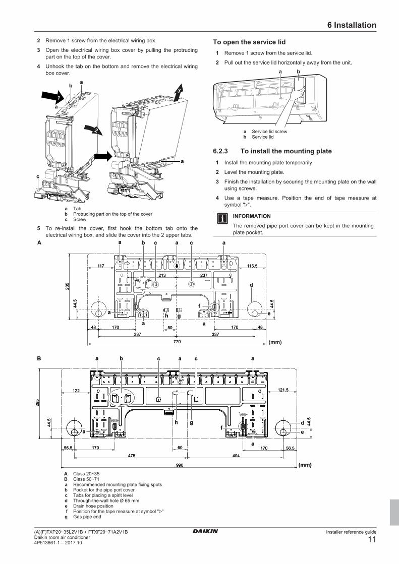
6.2.2 To open the indoor unit
To remove the front panel1 Hold the front panel by the panel tabs on both sides and open
it.
a
a Indentation on the unit
2 Remove the front panel by sliding it to the left or the right andpulling it toward you.
Result: The front panel shaft on 1 side will be disconnected.
3 Disconnect the front panel shaft on the other side in the samemanner.
a
a Front panel shaft
To re-install the front panel1 Attach the front panel. Align the shafts with the slots and push
them all the way in.
2 Close the front panel slowly and press on both sides at thecentre.
To remove the front grille
CAUTION
Wear adequate personal protective equipment (protectivegloves, safety glasses,…) when installing, maintaining orservicing the system.
1 Remove the front panel to remove the air filter.
2 Remove 2 screws (class 20~35) or 3 screws (class 50~71) fromthe front grille.
3 Push down the 3 upper hooks marked with a symbol with 3circles.
a
b
a
a Upper hookb Symbol with 3 circles
4 We recommend opening the flap before removing the frontgrille.
5 Place both hands under the centre of the front grille, push it upand then toward you.
1
2
To re-install the front grille1 Install the front grille and firmly engage the 3 upper hooks.
2 Install 2 screws (class 20~35) or 3 screws (class 50~71) backon the front grille.
3 Install the air filter and then mount the front panel.
To remove the electrical wiring box cover1 Remove the front grille.
6 Installation
Installer reference guide
11(A)(F)TXP20~35L2V1B + FTXF20~71A2V1BDaikin room air conditioner4P513661-1 – 2017.10
2 Remove 1 screw from the electrical wiring box.
3 Open the electrical wiring box cover by pulling the protrudingpart on the top of the cover.
4 Unhook the tab on the bottom and remove the electrical wiringbox cover.
a
a
c
b
a1
3
2
a Tabb Protruding part on the top of the coverc Screw
5 To re-install the cover, first hook the bottom tab onto theelectrical wiring box, and slide the cover into the 2 upper tabs.
To open the service lid1 Remove 1 screw from the service lid.
2 Pull out the service lid horizontally away from the unit.
a b
a Service lid screwb Service lid
6.2.3 To install the mounting plate1 Install the mounting plate temporarily.
2 Level the mounting plate.
3 Finish the installation by securing the mounting plate on the wallusing screws.
4 Use a tape measure. Position the end of tape measure atsymbol " ".
INFORMATION
The removed pipe port cover can be kept in the mountingplate pocket.
337
770
A
A
285
44.5
17048 48
44.5
116.5117
33750
213 237
170
a
ha a
g
aa
d
cb c
eaf
990
295
17060170
44.5
44.5
122 121.5
56.5 56.5
404475
PIPING HOLECENTER:170mmTO THE LEFT
PIPING HOLECENTER:170mmTO THE LEFT
a aab c c
h ga e
d
a
f
A
B
(mm)
337
770
A
A
285
44.5
17048 48
44.5
116.5117
33750
213 237
170
a
ha a
g
aa
d
cb c
eaf
990
295
17060170
44.5
44.5
122 121.5
56.5 56.5
404475
PIPING HOLECENTER:170mmTO THE LEFT
PIPING HOLECENTER:170mmTO THE LEFT
a aab c c
h ga e
d
a
f
A
B
(mm)
(mm)
A Class 20~35B Class 50~71a Recommended mounting plate fixing spotsb Pocket for the pipe port coverc Tabs for placing a spirit leveld Through-the-wall hole Ø 65 mme Drain hose positionf Position for the tape measure at symbol " "g Gas pipe end

6 Installation
Installer reference guide
12(A)(F)TXP20~35L2V1B + FTXF20~71A2V1B
Daikin room air conditioner4P513661-1 – 2017.10
h Liquid pipe end
6.2.4 To install the indoor unit
CAUTION
For walls containing a metal frame or a metal board, use awall embedded pipe and wall cover in the feed-throughhole to prevent possible heat, electrical shock, or fire.
NOTICE
Be sure to seal the gaps around the pipes with sealingmaterial (field supply), in order to prevent water leakage.
1 Bore a 65 mm large feed-through hole in the wall with adownward slope towards the outside.
2 Insert a wall pipe into the hole.
3 Insert a wall cover into the wall pipe.
Ø65
a b
c
4 After completing wiring, refrigerant piping and drain piping, doNOT forget to seal the gap with a putty.
NOTICE
▪ Do NOT bend refrigerant pipes.
▪ Do NOT push the refrigerant pipes onto the bottomframe or the front grille.
5 Cut off the pipe port cover from inside the front grille using acoping saw.
6 Remove any burrs along the cut section using a half roundneedle file.
NOTICE
Do NOT use nippers to remove the pipe port cover, as thiswould damage the front grille.
7 Remove the drain plug from the drain port and connect thedrain hose to the port.
NOTICE
Do NOT apply lubricating oil (refrigerant oil) to the drainplug when inserting it. The drain plug may deteriorate andcause drain leakage from the plug.
aa 4 mm hexagonal wrench
8 Shape the refrigerant pipes along the pipe path marking on themounting plate.
ab
c c d ea Drain hoseb Caulk this hole with putty or caulking material.c Adhesive vinyl taped Insulation tapee Mounting plate (accessory)
9 Pass the drain hose and refrigerant pipes through the wall hole.
10 Set the indoor unit on the mounting plate hooks. Use the " "marks as a guide.
11 Pull in the interconnection cable.
12 Connect the refrigerant pipes.
13 Wrap refrigerant pipes, interconnection cable and drain hosetogether using insulation tape. Overlap at least half the width ofthe tape with each turn.
d
e
cb
f
a
2×a Drain hoseb Interconnection cablec Mounting plate (accessory)d Refrigerant pipese Indoor unit fixing screw M4×12L (accessory)

6 Installation
Installer reference guide
13(A)(F)TXP20~35L2V1B + FTXF20~71A2V1BDaikin room air conditioner4P513661-1 – 2017.10
f Bottom frame
14 Take care so the interconnection cable does NOT catch indoorunit.
15 Press the bottom edge of indoor unit with both hands until it isfirmly caught by the mounting plate hooks.
16 Secure the indoor unit to the mounting plate using 2 indoor unitfixing screws M4×12L (accessory).
Wall embedded piping17 Insert the drain hose in the drain pipe as shown in the following
figure, so it will NOT be pulled out of the drain pipe.
≥50
mm
To connect the piping on right side, right-back, orright-bottom
INFORMATION
The factory default is right-side piping. For left-side piping,remove the piping from the right side and install it on theleft side.
1 Attach the drain hose with adhesive vinyl tape to the bottom ofthe refrigerant pipes.
2 Wrap the drain hose and the refrigerant pipes together usinginsulation tape.
A
BC
a bA Right-side pipingB Right-bottom pipingC Right-back pipinga Remove the pipe port cover here for right-side piping.b Remove the pipe port cover here for right-bottom piping.
3 Pass the drain hose and refrigerant pipes through the wall hole.
4 Set the indoor unit on the mounting plate hooks. Use the " "marks as a guide.
ba
c
a Mounting plate (accessory)b Interconnection cablec Wire guide
5 Open the front panel, and then the service lid. Refer to"6.2.2 To open the indoor unit" on page 10.
6 Pass the interconnection cable from the outdoor unit throughthe feed-through wall hole, through the back of the indoor unitand through the front side. (In case the interconnection cablewas stripped in advance, cover the ends with insulating tape.)
7 Bend the end of the cable up.
8 Press the bottom frame of the unit with both hands to set it onthe bottom hooks of the mounting. Make sure that the wires doNOT get squeezed anywhere.
To connect the piping on left side, left-back, orleft-bottom
INFORMATION
The factory default is is right-side piping. For left-sidepiping, remove the piping from the right side and install iton the left side.
1 Remove the insulation fixing screw on the right side andremove the drain hose.
2 Remove the drain plug on the left side and attach it to the rightside.
3 Insert the drain hose and do not forget to tighten it with thefixing screw; otherwise water leakage may occur.
a
b
a
b
a Insulation fixing screwb Drain hose
4 Attach the drain hose to the refrigerant pipes bottom side usingadhesive vinyl tape.
A
BC
b
a
A Left-side pipingB Left-back pipingC Left-bottom pipinga Remove the pipe port cover here for left-side piping.b Remove the pipe port cover here for left-bottom piping.
6.2.5 To provide drainageMake sure condensation water can be evacuated properly. Thisinvolves:
▪ General guidelines
▪ Connecting the drain piping to the indoor unit
▪ Checking for water leaks
General guidelines▪ Pipe length. Keep drain piping as short as possible.
▪ Pipe size. Keep the pipe size equal to or greater than that of theconnecting pipe (vinyl pipe of 16 mm nominal diameter and18 mm outer diameter).
Ø16 Ø18

6 Installation
Installer reference guide
14(A)(F)TXP20~35L2V1B + FTXF20~71A2V1B
Daikin room air conditioner4P513661-1 – 2017.10
NOTICE
▪ Install the drain hose with a downward slope.
▪ Traps are NOT permitted.
▪ Do NOT put the end of the hose in water.
▪ Drain hose extension. To extend the drain hose, use a fieldsupplied Ø16 mm hose. Do NOT forget to use heat insulation tubeon the indoor section of the extension hose.
a a b c
Ø16
Ø16
a Drain hose supplied with the indoor unitb Heat insulation tube (field supply)c Extension drain hose
▪ Rigid polyvinyl chloride pipe. When connecting a rigid polyvinylchloride pipe (Ø13 mm) directly to the drain hose, use a fieldsupplied drain socket (Ø13 mm).a b c
Ø18
a Drain hose supplied with the indoor unitb Ø13 mm drain socket (field supply)c Rigid polyvinyl chloride pipe (field supply)
▪ Condensation. Take measures against condensation. Insulatethe complete drain piping in the building.
To check for water leaks1 Remove the air filters.
2 Gradually pour approximately 1 l of water in the drain pan, andcheck for water leaks.
6.2.6 To connect optional accessories (wireduser interface, central user interface,wireless adapter, etc.)
1 Remove the electrical wiring box cover (refer to "To remove theelectrical wiring box cover" on page 10).
2 Attach the connection cable to the S21 connector and pull thewire harness as shown in the following figure.
a
b
c
a S21 wire harness routing for wireless adapterb S21 wire harness routing for other applicationsc S21 connector
3 Put the electrical wiring box cover back and pull the wireharness around it as shown in the figure above.
6.2.7 To install the wireless adapterFor class 20, 25, 35
1
2
1
1 Place the wireless adapter against the hooks.
2 Lock the adapter by pressing it down.
3 For removal, perform the above steps in reverse order.
For class 50, 60, 71
1
2
4 Place the wireless adapter into the holder.
5 Fix the adapter in the holder by pressing down on it.
6 For removal, bend one clamp of the holder with a finger torelease the wireless adapter and remove it from the holder.

6 Installation
Installer reference guide
15(A)(F)TXP20~35L2V1B + FTXF20~71A2V1BDaikin room air conditioner4P513661-1 – 2017.10
1
2
6.2.8 To set a different addressIn case 2 indoor units are installed in 1 room, different addresses for2 user interfaces can be set.
1 Remove the batteries from the user interface.
2 Cut the address jumper.
a a
a Address jumper
NOTICE
Be careful NOT to damage any of the surrounding partswhen cutting the address jumper.
3 Turn the power supply on.
Result: The flap of the indoor unit will open and close to set thereference position.
INFORMATION
▪ For FTXF-A units, the following setting MUST becompleted within 5 minutes after the power supply isturned on.
▪ In case you could NOT complete the setting in time,turn the power supply off and wait at least 1 minutebefore turning the power supply back on.
4 Press simultaneously:
Model ButtonsFTXP-L and ATXP-L , and FTXF-A
, and
5 Press:
Model ButtonFTXP-L and ATXP-L
FTXF-A
6 Select:
Model SymbolFTXP-L and ATXP-LFTXF-A
7 Press:
Model ButtonFTXP-L and ATXP-L
FTXF-A
ON/OFF
a
b
a Operation lampb Indoor unit ON/OFF switch
8 Press the indoor unit ON/OFF switch while the operation lampis blinking.
Jumper AddressFactory setting 1After cutting with nippers 2
INFORMATION
If the setting could NOT be completed while the operationlamp was blinking, repeat the setting process from thebeginning.
9 When the setting is complete, press:
Model ButtonFTXP-L and ATXP-L Keep pressed for about
5 seconds.FTXF-A
Result: The user interface will return to the previous screen.
6.3 Connecting the refrigerant piping
6.3.1 About connecting the refrigerant pipingBefore connecting the refrigerant pipingMake sure the outdoor and indoor unit are mounted.
Typical workflowConnecting the refrigerant piping involves:
▪ Connecting the refrigerant piping to the indoor unit
▪ Connecting the refrigerant piping to the outdoor unit
▪ Insulating the refrigerant piping
▪ Keeping in mind the guidelines for:
▪ Pipe bending
▪ Flaring pipe ends
▪ Using the stop valves
6.3.2 Precautions when connecting therefrigerant piping
INFORMATION
Also read the precautions and requirements in thefollowing chapters:
▪ General safety precautions
▪ Preparation
DANGER: RISK OF BURNING

6 Installation
Installer reference guide
16(A)(F)TXP20~35L2V1B + FTXF20~71A2V1B
Daikin room air conditioner4P513661-1 – 2017.10
CAUTION
▪ Do NOT use mineral oil on flared part.
▪ NEVER install a drier to this R32 unit to guarantee itslifetime. The drying material may dissolve and damagethe system.
CAUTION
▪ Use the flare nut fixed to the main unit.
▪ To prevent gas leakage, apply refrigeration oil only tothe inside of the flare. Use refrigeration oil for R32.
▪ Do NOT reuse joints.
NOTICE
Take the following precautions on refrigerant piping intoaccount:
▪ Avoid anything but the designated refrigerant to getmixed into the refrigerant cycle (e.g. air).
▪ Only use R32 when adding refrigerant.
▪ Only use installation tools (e.g. manifold gauge set) thatare exclusively used for R32 installations to withstandthe pressure and to prevent foreign materials (e.g.mineral oils and moisture) from mixing into the system.
▪ Install the piping so that the flare is NOT subjected tomechanical stress.
▪ Protect the piping as described in the following table toprevent dirt, liquid or dust from entering the piping.
▪ Use caution when passing copper tubes through walls(see figure below).
Unit Installation period Protection methodOutdoor unit >1 month Pinch the pipe
<1 month Pinch or tape the pipeIndoor unit Regardless of the
period
INFORMATION
Do NOT open the refrigerant stop valve before checkingthe refrigerant piping. When you need to charge additionalrefrigerant it is recommended to open the refrigerant stopvalve after charging.
6.3.3 Guidelines when connecting therefrigerant piping
Take the following guidelines into account when connecting pipes:
▪ Coat the flare inner surface with ether oil or ester oil whenconnecting a flare nut. Tighten 3 or 4 turns by hand, beforetightening firmly.
▪ ALWAYS use 2 wrenches together when loosening a flare nut.
▪ ALWAYS use a spanner and torque wrench together to tighten theflare nut when connecting the piping. This to prevent nut crackingand leaks.
a b
c
d
a Torque wrenchb Spannerc Piping uniond Flare nut
Piping size(mm)
Tighteningtorque (N•m)
Flaredimensions (A)
(mm)
Flare shape(mm)
Ø6.4 15~17 8.7~9.1
R=0.4~0.8
45° ±2
90°±2
AØ9.5 33~39 12.8~13.2Ø12.7 50~60 16.2~16.6Ø15.9 63~75 19.3~19.7
6.3.4 Pipe bending guidelinesUse a pipe bender for bending. All pipe bends should be as gentleas possible (bending radius should be 30~40 mm or larger).
6.3.5 To flare the pipe end
CAUTION
▪ Incomplete flaring may cause refrigerant gas leakage.
▪ Do NOT re-use flares. Use new flares to preventrefrigerant gas leakage.
▪ Use flare nuts that are included with the unit. Usingdifferent flare nuts may cause refrigerant gas leakage.
1 Cut the pipe end with a pipe cutter.
2 Remove burrs with the cut surface facing down so that thechips do NOT enter the pipe.
a ba Cut exactly at right angles.b Remove burrs.
3 Remove the flare nut from the stop valve and put the flare nuton the pipe.
4 Flare the pipe. Set exactly at the position as shown in thefollowing figure.
A
Flare tool for R32(clutch type)
Conventional flare toolClutch type
(Ridgid-type)
Wing nut type
(Imperial-type)A 0~0.5 mm 1.0~1.5 mm 1.5~2.0 mm
5 Check that the flaring is properly made.
a b
c
a Flare’s inner surface MUST be flawless.b The pipe end MUST be evenly flared in a perfect circle.c Make sure the flare nut is fitted.

6 Installation
Installer reference guide
17(A)(F)TXP20~35L2V1B + FTXF20~71A2V1BDaikin room air conditioner4P513661-1 – 2017.10
6.3.6 To connect the refrigerant piping to theindoor unit
▪ Pipe length. Keep refrigerant piping as short as possible.
▪ Flare connections. Connect refrigerant piping to the unit usingflare connections.
▪ Insulation. Insulate the refrigerant piping, interconnection cableand drain hose on the indoor unit as follows:
c
abf
d
g
e
a Gas pipeb Gas pipe insulationc Interconnection cabled Liquid pipee Liquid pipe insulationf Finishing tapeg Drain hose
NOTICE
Make sure to insulate all refrigerant piping. Any exposedpiping might cause condensation.
6.4 Connecting the electrical wiring
6.4.1 About connecting the electrical wiringTypical workflowConnecting the electrical wiring typically consists of the followingstages:1 Making sure the power supply system complies with the
electrical specifications of the units.2 Connecting the electrical wiring to the outdoor unit.3 Connecting the electrical wiring to the indoor unit.4 Connecting the main power supply.
6.4.2 Precautions when connecting theelectrical wiring
INFORMATION
Also read the precautions and requirements in thefollowing chapters:
▪ General safety precautions
▪ Preparation
DANGER: RISK OF ELECTROCUTION
WARNING
ALWAYS use multicore cable for power supply cables.
WARNING
If the supply cord is damaged, it MUST be replaced by themanufacturer, its service agent or similarly qualifiedpersons in order to avoid a hazard.
WARNING
Do NOT connect the power supply to the indoor unit. Thiscould result in electrical shock or fire.
WARNING
▪ Do NOT use locally purchased electrical parts insidethe product.
▪ Do NOT branch the power supply for the drain pump,etc. from the terminal block. This could result inelectrical shock or fire.
WARNING
Keep the interconnection wiring away from copper pipeswithout thermal insulation as such pipes will be very hot.
6.4.3 Guidelines when connecting the electricalwiring
Keep the following in mind:
▪ If stranded conductor wires are used, install a round crimp-styleterminal on the end of the wire. Place the round crimp-styleterminal on the wire up to the covered part and fasten the terminalwith the appropriate tool.
b aa Stranded conductor wireb Round crimp-style terminal
▪ Use the following methods for installing wires:
Wire type Installation methodSingle-core wire c b
c
aa
AAA´
A´
a Curled single-core wire
b Screw
c Flat washerStranded conductorwire with roundcrimp-style terminal
c b ba c
a
BB
a Terminal
b Screw
c Flat washer
O Allowed
X NOT allowed
Tightening torques
Item Tightening torque (N•m)M4 (X1M) 1.2~1.5M4 (earth)
6.4.4 Specifications of standard wiringcomponents
ComponentInterconnection cable(indoor↔outdoor)
4-core cable ≥1.5 mm²and applicable for
220~240 V
7 Commissioning
Installer reference guide
18(A)(F)TXP20~35L2V1B + FTXF20~71A2V1B
Daikin room air conditioner4P513661-1 – 2017.10
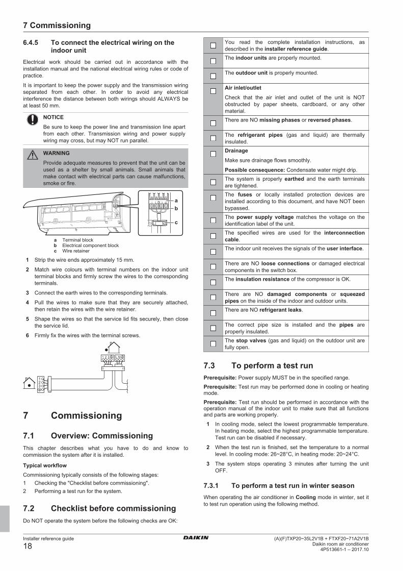
6.4.5 To connect the electrical wiring on theindoor unit
Electrical work should be carried out in accordance with theinstallation manual and the national electrical wiring rules or code ofpractice.
It is important to keep the power supply and the transmission wiringseparated from each other. In order to avoid any electricalinterference the distance between both wirings should ALWAYS beat least 50 mm.
NOTICE
Be sure to keep the power line and transmission line apartfrom each other. Transmission wiring and power supplywiring may cross, but may NOT run parallel.
WARNING
Provide adequate measures to prevent that the unit can beused as a shelter by small animals. Small animals thatmake contact with electrical parts can cause malfunctions,smoke or fire.
ab
c
a Terminal blockb Electrical component blockc Wire retainer
1 Strip the wire ends approximately 15 mm.
2 Match wire colours with terminal numbers on the indoor unitterminal blocks and firmly screw the wires to the correspondingterminals.
3 Connect the earth wires to the corresponding terminals.
4 Pull the wires to make sure that they are securely attached,then retain the wires with the wire retainer.
5 Shape the wires so that the service lid fits securely, then closethe service lid.
6 Firmly fix the wires with the terminal screws.
7 Commissioning
7.1 Overview: CommissioningThis chapter describes what you have to do and know tocommission the system after it is installed.
Typical workflowCommissioning typically consists of the following stages:1 Checking the "Checklist before commissioning".2 Performing a test run for the system.
7.2 Checklist before commissioningDo NOT operate the system before the following checks are OK:
You read the complete installation instructions, asdescribed in the installer reference guide.The indoor units are properly mounted.
The outdoor unit is properly mounted.
Air inlet/outlet
Check that the air inlet and outlet of the unit is NOTobstructed by paper sheets, cardboard, or any othermaterial.There are NO missing phases or reversed phases.
The refrigerant pipes (gas and liquid) are thermallyinsulated.Drainage
Make sure drainage flows smoothly.
Possible consequence: Condensate water might drip.The system is properly earthed and the earth terminalsare tightened.The fuses or locally installed protection devices areinstalled according to this document, and have NOT beenbypassed.The power supply voltage matches the voltage on theidentification label of the unit.The specified wires are used for the interconnectioncable.The indoor unit receives the signals of the user interface.
There are NO loose connections or damaged electricalcomponents in the switch box.The insulation resistance of the compressor is OK.
There are NO damaged components or squeezedpipes on the inside of the indoor and outdoor units.There are NO refrigerant leaks.
The correct pipe size is installed and the pipes areproperly insulated.The stop valves (gas and liquid) on the outdoor unit arefully open.
7.3 To perform a test runPrerequisite: Power supply MUST be in the specified range.
Prerequisite: Test run may be performed done in cooling or heatingmode.
Prerequisite: Test run should be performed in accordance with theoperation manual of the indoor unit to make sure that all functionsand parts are working properly.
1 In cooling mode, select the lowest programmable temperature.In heating mode, select the highest programmable temperature.Test run can be disabled if necessary.
2 When the test run is finished, set the temperature to a normallevel. In cooling mode: 26~28°C, in heating mode: 20~24°C.
3 The system stops operating 3 minutes after turning the unitOFF.
7.3.1 To perform a test run in winter seasonWhen operating the air conditioner in Cooling mode in winter, set itto test run operation using the following method.
8 Hand-over to the user
Installer reference guide
19(A)(F)TXP20~35L2V1B + FTXF20~71A2V1BDaikin room air conditioner4P513661-1 – 2017.10
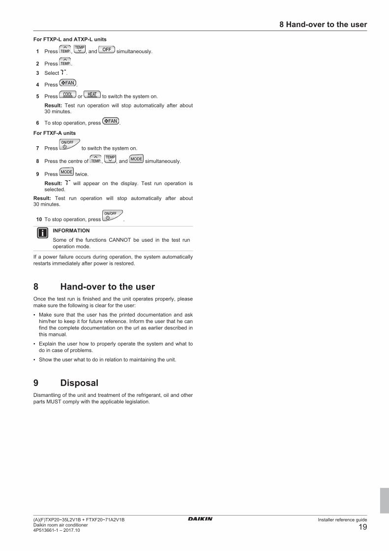
For FTXP-L and ATXP-L units
1 Press , , and simultaneously.
2 Press .
3 Select .
4 Press .
5 Press or to switch the system on.
Result: Test run operation will stop automatically after about30 minutes.
6 To stop operation, press .
For FTXF-A units
7 Press to switch the system on.
8 Press the centre of , , and simultaneously.
9 Press twice.
Result: will appear on the display. Test run operation isselected.
Result: Test run operation will stop automatically after about30 minutes.
10 To stop operation, press .
INFORMATION
Some of the functions CANNOT be used in the test runoperation mode.
If a power failure occurs during operation, the system automaticallyrestarts immediately after power is restored.
8 Hand-over to the userOnce the test run is finished and the unit operates properly, pleasemake sure the following is clear for the user:
▪ Make sure that the user has the printed documentation and askhim/her to keep it for future reference. Inform the user that he canfind the complete documentation on the url as earlier described inthis manual.
▪ Explain the user how to properly operate the system and what todo in case of problems.
▪ Show the user what to do in relation to maintaining the unit.
9 DisposalDismantling of the unit and treatment of the refrigerant, oil and otherparts MUST comply with the applicable legislation.

10 Technical data
Installer reference guide
20(A)(F)TXP20~35L2V1B + FTXF20~71A2V1B
Daikin room air conditioner4P513661-1 – 2017.10
10 Technical dataA subset of the latest technical data is available on the regional Daikin website (publicly accessible). The full set of latest technical data isavailable on the Daikin extranet (authentication required).
10.1 Wiring diagram
Unified Wiring Diagram LegendFor applied parts and numbering refer to the wiring diagram sticker supplied on the unit. Part numbering is realized by Arabic numbers in ascending order for each part and
is represented in the overview below by symbol “*” in the part code.
: CIRCUIT BREAKER : PROTECTIVE EARTH
: CONNECTION : PROTECTIVE EARTH (SCREW)
, : CONNECTOR A : RECTIFIER
: EARTH : RELAY CONNECTOR
: FIELD WIRING : SHORT CIRCUIT CONNECTOR
: FUSE : TERMINAL
INDOOR
: INDOOR UNIT : TERMINAL STRIP
OUTDOOR
: OUTDOOR UNIT : WIRE CLAMP
BLK : BLACK GRN : GREEN PNK : PINK WHT : WHITE
BLU : BLUE GRY : GREY PRP, PPL : PURPLE YLW : YELLOW
BRN : BROWN ORG : ORANGE RED : RED
A*P : PRINTED CIRCUIT BOARD PS : SWITCHING POWER SUPPLY
BS* : PUSH BUTTON ON / OFF, OPERATION SWITCH PTC* : THERMISTOR PTC
BZ, H*O : BUZZER Q* : INSULATED GATE BIPOLAR TRANSISTOR (IGBT)
C* : CAPACITOR Q*DI : EARTH LEAK CIRCUIT BREAKER
AC*, CN*, E*, HA*, HE, HL*, HN*, HR*, MR*_A, MR*_B, S*, U, V, W, X*A, K*R_*
: CONNECTION, CONNECTOR Q*L : OVERLOAD PROTECTOR
D*, V*D : DIODE Q*M : THERMO SWITCH
DB* : DIODE BRIDGE R* : RESISTOR
DS* : DIP SWITCH R*T : THERMISTOR
E*H : HEATER RC : RECEIVER
F*U, FU* (FOR CHARACTERISTICS REFER TO PCB INSIDE YOUR UNIT)
: FUSE S*C : LIMIT SWITCH
FG* : CONNECTOR (FRAME GROUND) S*L : FLOAT SWITCH
H* : HARNESS S*NPH : PRESSURE SENSOR (HIGH)
H*P, LED*, V*L : PILOT LAMP, LIGHT EMITTING DIODE S*NPL : PRESSURE SENSOR (LOW)
HAP : LIGHT EMITTING DIODE (SERVICE MONITOR GREEN) S*PH, HPS* : PRESSURE SWITCH (HIGH)
HIGH VOLTAGE : HIGH VOLTAGE S*PL : PRESSURE SWITCH (LOW)
IES : INTELLIGENT EYE SENSOR S*T : THERMOSTAT
IPM* : INTELLIGENT POWER MODULE S*W, SW* : OPERATION SWITCH
K*R, KCR, KFR, KHuR, K*M : MAGNETIC RELAY SA*, F1S : SURGE ARRESTOR
L : LIVE SR*, WLU : SIGNAL RECEIVER
L* : COIL SS* : SELECTOR SWITCH
L*R : REACTOR SHEET METAL : TERMINAL STRIP FIXED PLATE
M* : STEPPER MOTOR T*R : TRANSFORMER
M*C : COMPRESSOR MOTOR TC, TRC : TRANSMITTER
M*F : FAN MOTOR V*, R*V : VARISTOR
M*P : DRAIN PUMP MOTOR V*R : DIODE BRIDGE
M*S : SWING MOTOR WRC : WIRELESS REMOTE CONTROLLER
MR*, MRCW*, MRM*, MRN* : MAGNETIC RELAY X* : TERMINAL
N ::
NEUTRAL X*M : TERMINAL STRIP (BLOCK)
n = *, N=* NUMBER OF PASSES THROUGH FERRITE CORE Y*E : ELECTRONIC EXPANSION VALVE COIL
PAM : PULSE-AMPLITUDE MODULATION Y*R, Y*S : REVERSING SOLENOID VALVE COIL
PCB* : PRINTED CIRCUIT BOARD Z*C : FERRITE CORE
PM* : POWER MODULE ZF, Z*F : NOISE FILTER
CIRCUIT BREAKER
11 Glossary
Installer reference guide
21(A)(F)TXP20~35L2V1B + FTXF20~71A2V1BDaikin room air conditioner4P513661-1 – 2017.10
11 GlossaryDealer
Sales distributor for the product.
Authorized installerTechnical skilled person who is qualified to install theproduct.
UserPerson who is owner of the product and/or operates theproduct.
Applicable legislationAll international, European, national and local directives,laws, regulations and/or codes that are relevant andapplicable for a certain product or domain.
Service companyQualified company which can perform or coordinate therequired service to the product.
Installation manualInstruction manual specified for a certain product orapplication, explaining how to install, configure and maintainit.
Operation manualInstruction manual specified for a certain product orapplication, explaining how to operate it.
Maintenance instructionsInstruction manual specified for a certain product orapplication, which explains (if relevant) how to install,configure, operate and/or maintain the product orapplication.
AccessoriesLabels, manuals, information sheets and equipment that aredelivered with the product and that need to be installedaccording to the instructions in the accompanyingdocumentation.
Optional equipmentEquipment made or approved by Daikin that can becombined with the product according to the instructions inthe accompanying documentation.
Field supplyEquipment NOT made by Daikin that can be combined withthe product according to the instructions in theaccompanying documentation.


4P513661-1 2017.10
Cop
yrig
ht 2
017
Dai
kin