1112_ehv+xlpe+cable%280229%29
DESCRIPTION
Power CableTRANSCRIPT


One of the World’s largest cable manufacturing plants currently built to suit the global demand in the field of Energy and Telecommunications.
It is also a nation’s leading environment-friendly plant that can not only manufacture wide range of Power Cables from MV/LV to EHV but is also able to produce all sort of telecommunication cables and industrial products at all levels.
Through more than 56 years of its core business in the field of power and telecommunication cables, TAIHAN is gearing up to be a global leading solution provider.
Based on its corporate values of harmony and trust, we will share our vision with our stakeholders, employees, customers and our investors.
TAIHAN will definitely bring a more prosperous future in the years to come.
TAIHAN's All - New Production Plant in DangJin


Introduction of XLPE Cable & AccessoriesIntroductionCable Specification
XLPE CableDesign and Construction of XLPE Cable
ManufacturingManufacturing ProcessVCV LineCDCC SystemQuility Assurance & Test Requirement
EngineeringSystem Design and Engineering WorkInstallation
Accessories
Diagnosis System
AppendixCertificates
7 8
10
20212224
2527
29
34
38

6
TAIHAN provides turnkey cabling solutions to ensure the reliability of energy networks
Having led the establishment of the nation’s power network for the half-century, TAIHAN has led the development of extra high voltage cables since the 1970s and been recognized for the world class technology in XLPE underground cable. We have continued to increase its technology to 230kV and 345kV XLPE cables through advancement of technology and facilities. In step with the ever increasing power consumption and the expansion of extra high voltage cable demand, we reinforced the production capacity by equipping the 125 meters high VCV Tower, to produce high quality extra high voltage XLPE cable up to 500kV grade. Furthermore, we produce and supply quality accessories and joints materials for extra high voltage cables. From raw materials, production process, testing of products, to network design & installation, we have strictly controlled the quality of products and elevated ourselves to an extra high voltage cable specialist trusted by the world’s major markets including Asia, Middle East, US, and Australia.

Introduction of XLPE Cable
XLPE(Cross-Linked Polyethylene) insulated cables have been widely used for electric power distribution of voltage up to 30kV grade since they were develpoed in 1960 to replace the paper insulated cables and other thermoplastic insulated cables. XLPE cables have many excellent characteristics, especially for use in higher operating temperature. Generally PE insulated cables can be used in maximum operating temperature of 70°C and paper insulated cables in 85°C, but XLPE cables, which have more compact crystallity than PE by cross-linking process, can be used up to 90°C in normal condition. The major merits of XLPE cables can be illustrated as follows;
XLPE cables, however, had been scarcely used for extra high voltage exceeding 30kV grade because of its weakness for water treeing phenomena which occurs in the insulation in long-term operating situation. Water treeing is a phenomena of gradual insulation destroying due to water concentration onto some weak points in the insulation.
The water can be invaded through the polymeric materials in gaseous states and /or contained in insulation materials together with small voids and impurities during extrusion, steam-curing and cooling process. These waters can be con-centrated onto weak points due to high electric intensity and repeating switching operation, and eventually formed a treeshaped tunnel from inside to outer surface of insulation.
But nowadays, with the aid of technical development in cable manufacturing field, water treeing phenomenacannot be an obstacle any more to extent the voltage grade higher. Water invasion from the outside of cable can be prevented by adopting water-proof seamless metal sheath and water contents in insulation during manufacturing process can be practically minimized by adopting dry curing cross-linking process instead of steam-curing method.
Many researches and develpoments are accomplished in many develpoed countries including ourselves and it shows excellent operating experiences. 66kV and 77kV grade XLPE cables have already been used since early 1970s and now XLPE cables up to and including 230kV grade are popularly being adopted for power transmission lines. 345kV grade and 500kV grade cables are also developed and under operations.
Introduction of XLPE CableIntroduction
7

Introduction of XLPE Cable
Introduction of XLPE CableCables Specification
ScopeThis specification applies to materials and constructions of cross-linked polyethylene(XLPE) cables for extra high voltage transmission of rated voltage from 66kV grade upto and including 500kV grade. This specification deals manufacturer’s standard models of the cable, however any other models as for buyer’s standard are also available.
ConductorThe conductor shall be formed from plain copper or aluminum complying with Korean Standard KS C 3101, British Standard 6360/6791, IEC Publication 60228 or ICEA S-108-720. The conductor shall be stranded circular, compacted circular, or segmental compacted circular. Segmental compacted circular conductors shall be applied to cables of conductor nominal cross-sectional areas of 800mm2 and above.
Conductor Shielding Conductor shielding of an extruded semi-conducting thermosetting compound shall be applied over the conductor. One or two layer of semi-conducting tape(s) may be applied with a proper lapping between the conductor and the extruded semi-conducting layer.
InsulationThe insulation shall be of dry-cured XLPE compound with a thickness to meet dimensional, electrical and physical requirements specified. The compound shall be high quality, heat-,moisture-, ozone- and resitant. This insulation shall be suitable for operation in wet or dry locations at conductor temperature not exceeding 90°C for normal condition, 105°C for emergency overload conditions and 250°C for short circuit conditions.
Insulation ThicknessThe insulation thickness of XLPE cable must be based on its ability to withstand lightening impulse voltage as well as operating voltage throughout its expected life. For the design of XLPE cable, the nominal thickness of insulation is determined by AC withstand voltage(VAC) or impulse withstand voltage(Vimp), that can be determined by following formula. Larger value of TAC and Timp should be determined as minimum thickness of insulation.
Insulation ShieldingThe insulation shielding shall be applied direct upon the insulation and shall consist of either a semiconducting tape or a layer of extruded semi-conducting compound, or combination of these materials. The extruded semiconducting compound shall be a ther-mosetting or thermosetting compound and firmly and totally bonded to the insulation.
Matallic LayerThe metallic layer can be applied over the insulation shielding to reinforce the capability of carrying fault current specified, if required. The metallic layer will be one of the next forms; (Fig.1)
Fig.1
Copper Wire Shield Type
Metallic Sheath Type
Copper Wire Shield & Lead Alloy Sheath Type
Insulated Wires, Copper Wire Shield & LeadSheath Type (Enamelled Copper Wire Cable)
8

Introduction of XLPE Cable
Inner Plastic BeddingIf required, extruded layer of a thermoplastic compound, PVC or PE canbe applied.
Metal Tape Moisture BarrierWhen the moisture barrier required, a layer of aluminum tape laminated at both or outer side with copolymer shall be applied longitudinally over the cable core with an overlap so as to lap parts of the tape on each other.
Outer JacketThe outer jacket shall consist of thermoplastic compound(PVC, PE or similar materials) extruded continuously over the metallic layer or moisture barrier. A bituminous compound primer shall be applied under the outer jacket to protect the sheath against local corrosion when corrugated aluminum sheath or lead alloy sheath is adopted.
Copper Wire Shield (CWS) When a layer of copper wire shield is required, it shall be applied directly over the insulation shielding with a length of lay of approximately 10 times the diameter over the screen conductors and with gaps not less than 0.1mm, if not specified. One or more layers of suitable separator tape may be applied helically over a layer of CWS.
Corrugated AluminumWhen the corrugated aluminum sheath is required, it shall be applied by extrusion and then passing through a corrugating head. The corrugating head contains rotating dies to form the valleys between the ribs like sine wave and produce to correct diameter of sheath to fit over the insulation. The sheath shall be free from pinholes flaws and other imperfections. When the aluminum sheath is applied directly over the extruded semi-conducting layer or inner plastic bedding, suitable non-metallic tape(s) can be applied under the aluminum sheath to prevent heat transfer onto the plastic material during the manufacturing.
Lead AlloyWhen the lead alloy sheath is required, it shall be applied by a continuous screw extrusion in high quality, smooth surface and free from pinholes and any other imperfections including one associated with oxide inclusions. When the lead sheath is applied directly over the extruded semi-conducting layer or inner plastic bedding, suitable non-magnetic tape(s) can be applied under the lead sheath to prevent heat transfer onto the plastic material during the manufacturing. The composition of lead alloy of composition of Cu 0.04%, Te 0.04% and the remainder for lead will be applied.
9

XLPE CableDesign and Construction of XLPE Cable
Construction
TAC = VAC/EL(AC), Timp = Vimp/EL(imp)
Where,VAC : AC withstand voltageVimp : Impulse withstand voltage
1) Value of EL
EL(AC) : minimum breakdown stress obtained from weibull distribution plot for AC. (kV/mm)EL(imp): minimum breakdown stress obtained from weibull distribution for impulse. (kV/mm)
2) Value of VAC
*VAC = 3 x 1.1 x k1 x k2 x k3
Where,E0 : Nominal voltage(kV)K1 : Safety factorK2 : Deterioration coefficient of XLPE cable under electrical stressesK3: Temperature coefficient corresponding to the ratio of break down stresses of thecable at room temperature to those at maximum permissible temperature(90°C)
3) Value of Vimp
Vimp = BIL x K'1 x K'2 x K'3
Where,BIL : Basic impulse level (kV)k'1 : Safety factork'2 : Deterioration coefficient of XLPE cable under electrical stressesk'3 : Temperature coefficient corresponding to the ratio of breakdown stresses of thecable at room temperature to those at maximum permissible temperature (90°C)
EHV XLPE Cable
E0 1.5
10

EHV XLPE Cable
Design and Construction of XLPE Cable66kV Single Core Cable
Construction : Copper Conductor / XLPE Insulation / Aluminum Sheath / PVC (or PE) Outer Sheath
[Aluminum Sheath Type]
[Copper Wire Shield Type]
Construction : Copper Conductor / XLPE Insulation / Copper Wire Shield / PVC (or PE) Outer Sheath
200
250
325
400
500
600
800
1000
1200
1400
1600
1800
2000
NominalArea[mm²]
Conductor
Shape
Approx.Thickness
ofConductor
Shield[mm]
C.C
C.C
C.C
C.C
C.C
C.C
SEG
SEG
SEG
SEG
SEG
SEG
SEG
1.0
1.0
1.0
1.0
1.0
1.0
2.0
2.0
2.0
2.0
2.0
2.0
2.0
Thicknessof
Insulation[mm]
Approx.Thickness
ofInsulation
Shield[mm]
Thicknessof
Sheath[mm]
Thicknessof
Jacket[mm]
OverallDia.[mm]
Approx.Weight(kg / m)
11.0
11.0
11.0
11.0
11.0
11.0
11.0
11.0
11.0
11.0
11.0
11.0
11.0
1.5
1.5
1.5
1.5
1.5
1.5
1.5
1.5
1.5
1.5
1.5
1.5
1.5
1.5
1.6
1.6
1.7
1.7
1.8
1.9
2.0
2.1
2.1
2.2
2.3
2.3
3.5
3.5
3.5
3.5
3.5
3.5
3.5
3.5
3.5
3.5
3.5
3.5
3.5
64.0
67.0
70.0
74.0
76.0
80.0
87.0
92.0
98.0
101.0
105.0
108.0
111.0
5.2
5.9
7.0
8.1
9.1
10.4
13.2
15.6
18.0
20.3
22.5
24.5
26.9
* C.C : Circular Compacted, SEG : Segmental Compacted
200
250
325
400
500
600
800
1000
1200
1400
1600
1800
2000
NominalArea[mm²]
Conductor
Shape
Approx.Thickness
ofConductor
Shield[mm]
C.C
C.C
C.C
C.C
C.C
C.C
SEG
SEG
SEG
SEG
SEG
SEG
SEG
1.0
1.0
1.0
1.0
1.0
1.0
2.0
2.0
2.0
2.0
2.0
2.0
2.0
Thicknessof
Insulation[mm]
Approx.Thickness
ofInsulation
Shield[mm]
No. of
Wire[mm]
Thicknessof
Jacket[mm]
OverallDia.[mm]
Approx.Weight(kg / m)
11.0
11.0
11.0
11.0
11.0
11.0
11.0
11.0
11.0
11.0
11.0
11.0
11.0
1.5
1.5
1.5
1.5
1.5
1.5
1.5
1.5
1.5
1.5
1.5
1.5
1.5
40
40
40
40
40
40
40
40
40
40
40
40
40
3.5
3.5
3.5
4.0
4.0
4.0
4.5
4.5
4.5
4.5
4.5
4.5
4.5
56.0
58.0
60.0
64.0
67.0
69.0
77.0
81.0
85.0
89.0
92.0
95.0
98.0
4.5
5.1
5.9
6.9
8.0
9.1
11.7
13.7
15.7
17.9
19.8
21.8
23.8
* C.C : Circular Compacted, SEG : Segmental Compacted
Dia. of
Wire[mm]
1.2
1.2
1.2
1.2
1.2
1.2
1.2
1.2
1.2
1.2
1.2
1.2
1.2
11
EHV XLPE Cable
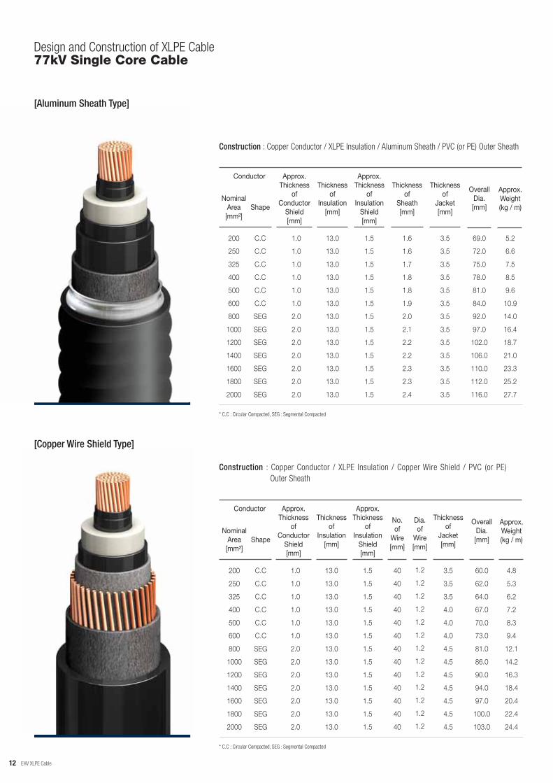
Design and Construction of XLPE Cable77kV Single Core Cable
[Aluminum Sheath Type]
[Copper Wire Shield Type]
Construction : Copper Conductor / XLPE Insulation / Aluminum Sheath / PVC (or PE) Outer Sheath
200
250
325
400
500
600
800
1000
1200
1400
1600
1800
2000
NominalArea[mm²]
Conductor
Shape
Approx.Thickness
ofConductor
Shield[mm]
C.C
C.C
C.C
C.C
C.C
C.C
SEG
SEG
SEG
SEG
SEG
SEG
SEG
1.0
1.0
1.0
1.0
1.0
1.0
2.0
2.0
2.0
2.0
2.0
2.0
2.0
Thicknessof
Insulation[mm]
Approx.Thickness
ofInsulation
Shield[mm]
Thicknessof
Sheath[mm]
Thicknessof
Jacket[mm]
OverallDia.[mm]
Approx.Weight(kg / m)
13.0
13.0
13.0
13.0
13.0
13.0
13.0
13.0
13.0
13.0
13.0
13.0
13.0
1.5
1.5
1.5
1.5
1.5
1.5
1.5
1.5
1.5
1.5
1.5
1.5
1.5
1.6
1.6
1.7
1.8
1.8
1.9
2.0
2.1
2.2
2.2
2.3
2.3
2.4
3.5
3.5
3.5
3.5
3.5
3.5
3.5
3.5
3.5
3.5
3.5
3.5
3.5
69.0
72.0
75.0
78.0
81.0
84.0
92.0
97.0
102.0
106.0
110.0
112.0
116.0
5.2
6.6
7.5
8.5
9.6
10.9
14.0
16.4
18.7
21.0
23.3
25.2
27.7
* C.C : Circular Compacted, SEG : Segmental Compacted
Construction : Copper Conductor / XLPE Insulation / Copper Wire Shield / PVC (or PE) Outer Sheath
200
250
325
400
500
600
800
1000
1200
1400
1600
1800
2000
NominalArea[mm²]
Conductor
Shape
Approx.Thickness
ofConductor
Shield[mm]
C.C
C.C
C.C
C.C
C.C
C.C
SEG
SEG
SEG
SEG
SEG
SEG
SEG
1.0
1.0
1.0
1.0
1.0
1.0
2.0
2.0
2.0
2.0
2.0
2.0
2.0
Thicknessof
Insulation[mm]
Approx.Thickness
ofInsulation
Shield[mm]
No. of
Wire[mm]
Thicknessof
Jacket[mm]
OverallDia.[mm]
Approx.Weight(kg / m)
13.0
13.0
13.0
13.0
13.0
13.0
13.0
13.0
13.0
13.0
13.0
13.0
13.0
1.5
1.5
1.5
1.5
1.5
1.5
1.5
1.5
1.5
1.5
1.5
1.5
1.5
40
40
40
40
40
40
40
40
40
40
40
40
40
3.5
3.5
3.5
4.0
4.0
4.0
4.5
4.5
4.5
4.5
4.5
4.5
4.5
60.0
62.0
64.0
67.0
70.0
73.0
81.0
86.0
90.0
94.0
97.0
100.0
103.0
4.8
5.3
6.2
7.2
8.3
9.4
12.1
14.2
16.3
18.4
20.4
22.4
24.4
* C.C : Circular Compacted, SEG : Segmental Compacted
Dia. of
Wire[mm]
1.2
1.2
1.2
1.2
1.2
1.2
1.2
1.2
1.2
1.2
1.2
1.2
1.2
12
EHV XLPE Cable
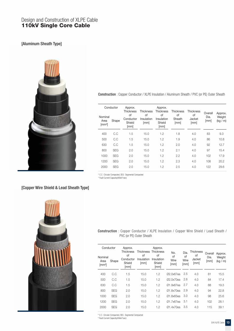
Design and Construction of XLPE Cable110kV Single Core Cable
[Aluminum Sheath Type]
Construction : Copper Conductor / XLPE Insulation / Aluminum Sheath / PVC (or PE) Outer Sheath
400
500
630
800
1000
1200
2000
NominalArea[mm²]
Conductor
Shape
Approx.Thickness
ofConductor
Shield[mm]
C.C
C.C
C.C
SEG
SEG
SEG
SEG
1.5
1.5
1.5
2.0
2.0
2.0
2.0
Thicknessof
Insulation[mm]
Approx.Thickness
ofInsulation
Shield[mm]
Thicknessof
Sheath[mm]
Thicknessof
Jacket[mm]
OverallDia.[mm]
Approx.Weight(kg / m)
15.0
15.0
15.0
15.0
15.0
15.0
15.0
1.2
1.2
1.2
1.2
1.2
1.2
1.2
1.8
1.9
2.0
2.1
2.2
2.3
2.5
4.0
4.0
4.0
4.0
4.0
4.0
4.0
83
86
92
97
102
108
122
9.3
10.8
12.7
15.4
17.9
20.2
29.6
* C.C : Circular Compacted, SEG : Segmental Compacted* Fault Current Capacity(40kA/1sec)
[Copper Wire Shield & Lead Sheath Type]
Construction : Copper Conductor / XLPE Insulation / Copper Wire Shield / Lead Sheath / PVC (or PE) Outer Sheath
400
500
630
800
1000
1200
2000
NominalArea[mm²]
Conductor
Shape
Approx.Thickness
ofConductor
Shield[mm]
C.C
C.C
C.C
SEG
SEG
SEG
SEG
1.5
1.5
1.5
2.0
2.0
2.0
2.0
Thicknessof
Insulation[mm]
Approx.Thickness
ofInsulation
Shield[mm]
No. of
Wire[mm]
Thicknessof
Jacket[mm]
OverallDia.[mm]
Approx.Weight(kg / m)
15.0
15.0
15.0
15.0
15.0
15.0
15.0
1.2
1.2
1.2
1.2
1.2
1.2
1.2
Ø2.0x67ea
Ø2.0x70ea
Ø1.9x67ea
Ø1.8x70ea
Ø1.8x65ea
Ø1.7x67ea
Ø1.4x70ea
4.0
4.0
4.0
4.0
4.0
4.0
4.0
81
84
88
94
98
102
115
15.5
17.4
19.3
22.8
25.6
28.1
39.1
* C.C : Circular Compacted, SEG : Segmental Compacted* Fault Current Capacity(40kA/1sec)
Dia. of
Wire[mm]
2.5
2.6
2.7
2.9
3.0
3.1
3.5
13
EHV XLPE Cable
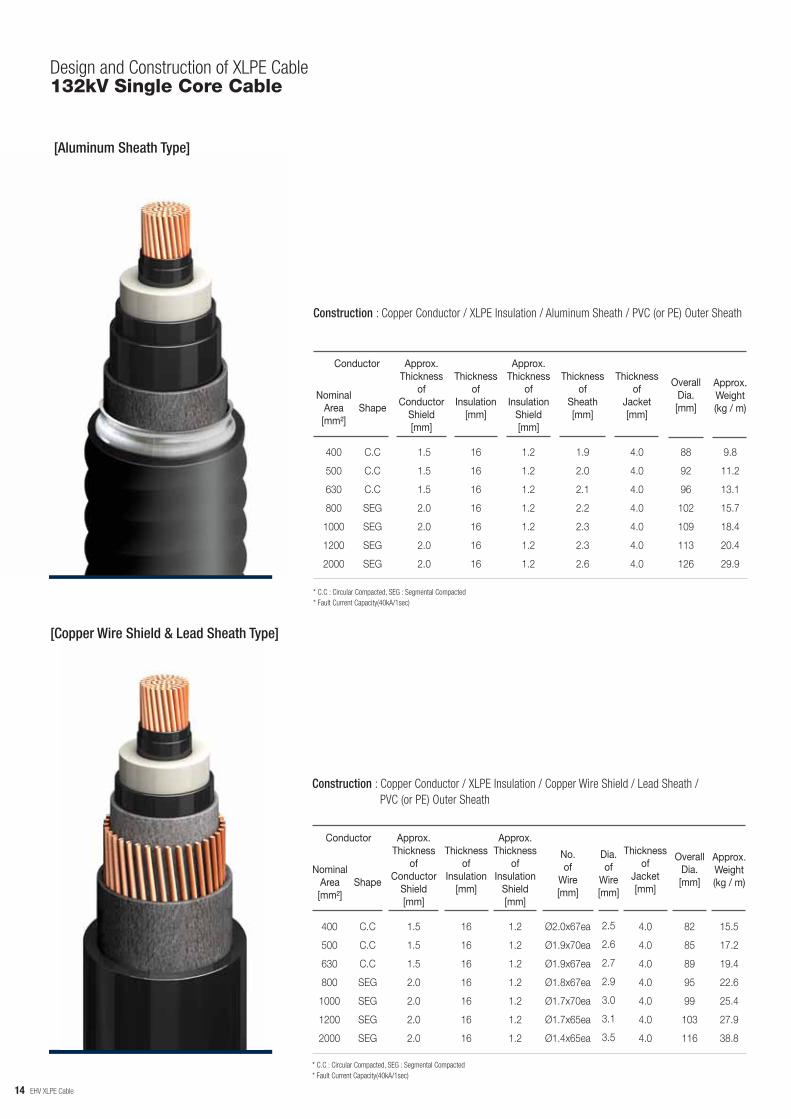
Design and Construction of XLPE Cable132kV Single Core Cable
[Aluminum Sheath Type]
[Copper Wire Shield & Lead Sheath Type]
Construction : Copper Conductor / XLPE Insulation / Aluminum Sheath / PVC (or PE) Outer Sheath
400
500
630
800
1000
1200
2000
NominalArea[mm²]
Conductor
Shape
Approx.Thickness
ofConductor
Shield[mm]
C.C
C.C
C.C
SEG
SEG
SEG
SEG
1.5
1.5
1.5
2.0
2.0
2.0
2.0
Thicknessof
Insulation[mm]
Approx.Thickness
ofInsulation
Shield[mm]
Thicknessof
Sheath[mm]
Thicknessof
Jacket[mm]
OverallDia.[mm]
Approx.Weight(kg / m)
16
16
16
16
16
16
16
1.2
1.2
1.2
1.2
1.2
1.2
1.2
1.9
2.0
2.1
2.2
2.3
2.3
2.6
4.0
4.0
4.0
4.0
4.0
4.0
4.0
88
92
96
102
109
113
126
9.8
11.2
13.1
15.7
18.4
20.4
29.9
* C.C : Circular Compacted, SEG : Segmental Compacted* Fault Current Capacity(40kA/1sec)
Construction : Copper Conductor / XLPE Insulation / Copper Wire Shield / Lead Sheath / PVC (or PE) Outer Sheath
400
500
630
800
1000
1200
2000
NominalArea[mm²]
Conductor
Shape
Approx.Thickness
ofConductor
Shield[mm]
C.C
C.C
C.C
SEG
SEG
SEG
SEG
1.5
1.5
1.5
2.0
2.0
2.0
2.0
Thicknessof
Insulation[mm]
Approx.Thickness
ofInsulation
Shield[mm]
No. of
Wire[mm]
Thicknessof
Jacket[mm]
OverallDia.[mm]
Approx.Weight(kg / m)
16
16
16
16
16
16
16
1.2
1.2
1.2
1.2
1.2
1.2
1.2
Ø2.0x67ea
Ø1.9x70ea
Ø1.9x67ea
Ø1.8x67ea
Ø1.7x70ea
Ø1.7x65ea
Ø1.4x65ea
4.0
4.0
4.0
4.0
4.0
4.0
4.0
82
85
89
95
99
103
116
15.5
17.2
19.4
22.6
25.4
27.9
38.8
* C.C : Circular Compacted, SEG : Segmental Compacted* Fault Current Capacity(40kA/1sec)
Dia. of
Wire[mm]
2.5
2.6
2.7
2.9
3.0
3.1
3.5
14

EHV XLPE Cable
Design and Construction of XLPE Cable154kV Single Core Cable
[Aluminum Sheath Type]
[Copper Wire Shield & Lead Sheath Type]
Construction : Copper Conductor / XLPE Insulation / Aluminum Sheath / PVC (or PE) Outer Sheath
600
1200
2000
2500
NominalArea[mm²]
Conductor
Shape
Approx.Thickness
ofConductor
Shield[mm]
C.C
SEG
SEG
SEG
1.5
2.0
2.0
2.0
Thicknessof
Insulation[mm]
Approx.Thickness
ofInsulation
Shield[mm]
Thicknessof
Sheath[mm]
Thicknessof
Jacket[mm]
OverallDia.[mm]
Approx.Weight(kg / m)
17
17
17
17
1.3
1.3
1.3
1.3
2.9
2.5
2.6
2.8
4.5
4.5
4.5
4.5
103
115
127
135
15.0
21.8
31.2
36.2
* C.C : Circular Compacted, SEG : Segmental Compacted* Fault Current Capacity(50kA/1.7sec)
Construction : Copper Conductor / XLPE Insulation / Copper Wire Shield / Lead Sheath / PVC (or PE) Outer Sheath
600
1200
2000
2500
NominalArea[mm²]
Conductor
Shape
Approx.Thickness
ofConductor
Shield[mm]
C.C
SEG
SEG
SEG
1.5
2.0
2.0
2.0
Thicknessof
Insulation[mm]
Approx.Thickness
ofInsulation
Shield[mm]
No. of
Wire[mm]
Thicknessof
Jacket[mm]
OverallDia.[mm]
Approx.Weight(kg / m)
17
17
17
17
1.3
1.3
1.3
1.3
Ø2.6x70ea
Ø2.5x65ea
Ø2.3x68ea
Ø2.2x66ea
4.5
4.5
4.5
4.5
95
109
122
129
22.7
31.7
42.7
48.5
* C.C : Circular Compacted, SEG : Segmental Compacted* Fault Current Capacity(40kA/1sec)
Dia. of
Wire[mm]
2.9
3.3
3.6
3.8
15

EHV XLPE Cable
Design and Construction of XLPE Cable230kV Single Core Cable
[Aluminum Sheath Type]
[Copper Wire Shield & Lead Sheath Type]
Construction : Copper Conductor / XLPE Insulation / Aluminum Sheath / PVC (or PE) Outer Sheath
600
1200
2000
2500
NominalArea[mm²]
Conductor
Shape
Approx.Thickness
ofConductor
Shield[mm]
C.C
SEG
SEG
SEG
1.5
2.0
2.0
2.0
Thicknessof
Insulation[mm]
Approx.Thickness
ofInsulation
Shield[mm]
Thicknessof
Sheath[mm]
Thicknessof
Jacket[mm]
OverallDia.[mm]
Approx.Weight(kg / m)
23
23
23
23
1.3
1.3
1.3
1.3
2.4
2.6
2.9
3.0
5.0
5.0
5.0
5.0
117
132
146
153
16.8
24.2
34.1
39.1
* C.C : Circular Compacted, SEG : Segmental Compacted* Fault Current Capacity (63kA/1sec)
Construction : Copper Conductor / XLPE Insulation / Copper Wire Shield / Lead Sheath / PVC (or PE) Outer Sheath
600
1200
2000
2500
NominalArea[mm²]
Conductor
Shape
Approx.Thickness
ofConductor
Shield[mm]
C.C
SEG
SEG
SEG
1.5
2.0
2.0
2.0
Thicknessof
Insulation[mm]
Approx.Thickness
ofInsulation
Shield[mm]
No. of
Wire[mm]
Thicknessof
Jacket[mm]
OverallDia.[mm]
Approx.Weight(kg / m)
23
23
23
23
1.3
1.3
1.3
1.3
Ø2.3x66ea
Ø2.2x68ea
Ø2.0x65ea
Ø1.9x65ea
5.0
5.0
5.0
5.0
108
121
134
141
25.7
35.0
46.7
52.4
* C.C : Circular Compacted, SEG : Segmental Compacted* Fault Current Capacity(63kA/1sec)
Dia. of
Wire[mm]
3.2
3.6
4.0
4.1
16

EHV XLPE Cable
Design and Construction of XLPE Cable345kV Single Core Cable
[Aluminum Sheath Type]
[Copper Wire Shield & Lead Sheath Type]
Construction : Copper Conductor / XLPE Insulation / Aluminum Sheath / PVC (or PE) Outer Sheath
600
1200
2000
2500
NominalArea[mm²]
Conductor
Shape
Approx.Thickness
ofConductor
Shield[mm]
C.C
SEG
SEG
SEG
1.5
2.0
2.0
2.0
Thicknessof
Insulation[mm]
Approx.Thickness
ofInsulation
Shield[mm]
Thicknessof
Sheath[mm]
Thicknessof
Jacket[mm]
OverallDia.[mm]
Approx.Weight(kg / m)
27
27
27
27
1.3
1.3
1.3
1.3
3.0
2.8
3.0
3.2
6.0
6.0
6.0
6.0
132
143
157
165
19.3
27.4
37.5
43.0
* C.C : Circular Compacted, SEG : Segmental Compacted* Fault Current Capacity(63kA/1.7sec)
Construction : Copper Conductor / XLPE Insulation / Copper Wire Shield / Lead Sheath / PVC (or PE) Outer Sheath
600
1200
2000
2500
NominalArea[mm²]
Conductor
Shape
Approx.Thickness
ofConductor
Shield[mm]
C.C
SEG
SEG
SEG
1.5
2.0
2.0
2.0
Thicknessof
Insulation[mm]
Approx.Thickness
ofInsulation
Shield[mm]
No. of
Wire[mm]
Thicknessof
Jacket[mm]
OverallDia.[mm]
Approx.Weight(kg / m)
17
17
17
17
1.3
1.3
1.3
1.3
Ø2.9x84ea
Ø2.9x81ea
Ø2.9x78ea
Ø2.9x75ea
6.0
6.0
6.0
6.0
119
132
145
153
31.2
41.1
53.0
60.2
* C.C : Circular Compacted, SEG : Segmental Compacted* Fault Current Capacity(63kA/1.7sec)
Dia. of
Wire[mm]
3.1
3.4
3.7
3.9
17
EHV XLPE Cable
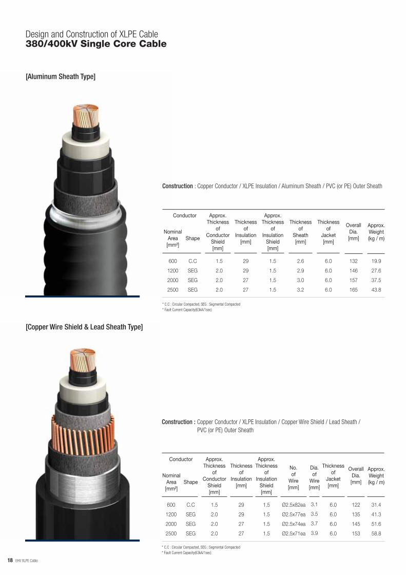
Design and Construction of XLPE Cable380/400kV Single Core Cable
[Aluminum Sheath Type]
[Copper Wire Shield & Lead Sheath Type]
Construction : Copper Conductor / XLPE Insulation / Aluminum Sheath / PVC (or PE) Outer Sheath
600
1200
2000
2500
NominalArea[mm²]
Conductor
Shape
Approx.Thickness
ofConductor
Shield[mm]
C.C
SEG
SEG
SEG
1.5
2.0
2.0
2.0
Thicknessof
Insulation[mm]
Approx.Thickness
ofInsulation
Shield[mm]
Thicknessof
Sheath[mm]
Thicknessof
Jacket[mm]
OverallDia.[mm]
Approx.Weight(kg / m)
29
29
27
27
1.5
1.5
1.5
1.5
2.6
2.9
3.0
3.2
6.0
6.0
6.0
6.0
132
146
157
165
19.9
27.6
37.5
43.8
* C.C : Circular Compacted, SEG : Segmental Compacted* Fault Current Capacity(63kA/1sec)
Construction : Copper Conductor / XLPE Insulation / Copper Wire Shield / Lead Sheath / PVC (or PE) Outer Sheath
600
1200
2000
2500
NominalArea[mm²]
Conductor
Shape
Approx.Thickness
ofConductor
Shield[mm]
C.C
SEG
SEG
SEG
1.5
2.0
2.0
2.0
Thicknessof
Insulation[mm]
Approx.Thickness
ofInsulation
Shield[mm]
No. of
Wire[mm]
Thicknessof
Jacket[mm]
OverallDia.[mm]
Approx.Weight(kg / m)
29
29
27
27
1.5
1.5
1.5
1.5
Ø2.5x82ea
Ø2.5x77ea
Ø2.5x74ea
Ø2.5x71ea
6.0
6.0
6.0
6.0
122
135
145
153
31.4
41.3
51.6
58.8
* C.C : Circular Compacted, SEG : Segmental Compacted* Fault Current Capacity(63kA/1sec)
Dia. of
Wire[mm]
3.1
3.5
3.7
3.9
18

EHV XLPE Cable
Design and Construction of XLPE Cable380/400kV Single Core Cable
[Insulated Wires, Copper Wire Shield & Lead Sheath Type]
[Copper Wire Shield & Aluminum-laminated Tape Type]
Construction : Copper Conductor with Insulated Wires / XLPE Insulation / Copper Wire Shield / Lead Sheath / PVC (or PE) Outer Sheath
* SEG : Segmental Compacted* Construction of metallic sheath is subject to change under the fault current condition.
2000
2500
NominalArea[mm²]
Conductor
Shape
Approx.Thickness
ofConductor
Shield[mm]
SEG
SEG
2.0
2.0
Thicknessof
Insulation[mm]
Approx.Thickness
ofInsulation
Shield[mm]
No. of
Wire[mm]
Thicknessof
Jacket[mm]
OverallDia.[mm]
Approx.Weight(kg / m)
27
27
1.5
1.5
Ø2.54x84ea
Ø2.54x79ea
6.0
6.0
152
160
55
61
Dia. of
Wire[mm]
4.0
4.0
Construction : Copper Conductor with Insulated Wires / XLPE Insulation / Copper Wire Shield / Lead Sheath / PVC (or PE) Outer Sheath
* SEG : Segmental Compacted
2000
2500
NominalArea[mm²]
Conductor
Shape
Approx.Thickness
ofConductor
Shield[mm]
SEG
SEG
2.0
2.0
Thicknessof
Insulation[mm]
Approx.Thickness
ofInsulation
Shield[mm]
No. of
Wire[mm]
Thicknessof
Jacket[mm]
OverallDia.[mm]
Approx.Weight(kg / m)
30
30
1.5
1.5
Ø2.6x66ea
Ø2.6x66ea
6.0
6.0
151
156
35
40
Dia. of
Wire[mm]
4.0
4.0
500kV Single Core Cable
19

Manufacturing
ManufacturingManufacturing Process
Inner Semi-Conductive PEInsulation XLPEOuter Semi-Conductive PE
WireDrawing
WireStranding
Copper or Aluminum Rod
Segmental
Circular or Compact Circular
Taping
Extrusion Dry CuringSimultaneous Process
Taping
ConductorAssembling
Conductor Binder
SemiConductive Tape
SemiConductive Tape
Leads Alloy Sheath
Leads Screw Extrusion
Jacket Extrusion
WireShield
WiringMachine
Jacket Extrusion
Jacket Extrusion
Copper Wire
Aluminum-FoilPE or PVC
Lead Alloy
Flooding CompoundPE or PVC
AluminumPress
CorrugatedAluminum Sheath
Aluminum
Flooding CompoundPE or PVC
Test &Delivery
Flow Chart of Manufacturing Process
20

Manufacturing
ManufacturingVCV Line
Vertical Type Continuous Vulcanizing Equipment
In case of extra high voltage cable, the insulation thickness is so thick that centers of the conductor and the insulation was not coincided each other when catenary type vulcanizing system was adopted. Due to the considerable eccentricity of the insulated core, the insulation thickness should be thicker than the electrically required value.
Our facility of vulcanizing process is installed in vertical in the tower of height of approximately 125m. The insulation is extruded on the highest place of the tower and passed through the vertical tube for vulcanizing and cooling purposes. Since the pass line of the insulated core is vertical, strengthen core is exposed to uniform gravity force through its cross-section that no eccentricity can be occurred. By adopting this method, the insulation thickness can be reduced remarkably and nowadays, and the extruded thermosetting insulated cables are enough competitive to conventional cables.
Metering Capstan
Conductor Preheater
Extruder(3 Layer Triple Common Extrusion)
N2 Gas
Heating Zone
ConductorAccumulator
Pay-off
CoolingZone
N2 Gas Tank
N2 Gas HeatExchanger
Reversing Wheel Water Water Tank
End SealTurn Wheel
Take-up
TensioningCaterpillar
21

Manufacturing
ManufacturingCDCC System
Completely Dry Curing and Cooling Vulcanizing Method
We adopt CDCC system for vulcanizing XLPE insulation that is a continuous vulcanizing and dry curing system using nitrogen gas. This CDCC system has been recently developed to produce extra high voltage XLPE cables and it shows excellent function to reduce faults and imperfections in the insulation.
In this system, extruded thermosetting compounds are cured in the curing tube by thermal radiation through inert nitrogen gas, therefore there is no opportunity that the compounds can absorb any moisture during vulcanizing process. The insulated core may be cooled by water in the lower part of the tube, but to obtain better quality in the absence of moisture, generally cooled by convection and radiation in a nitrogen gas atmosphere.
This system is being wholly controlled by computer so that manufacturing conditions and temperatures are controlled perfectly. These mean that the quality of the insulation is uniform throughout the cross-section and the length. All of the process of this system is perfectly protected from outer atmosphere to prevent the insulation compounds and the insulated core from any contact with moistures, dust, contaminated air, etc.
22

Manufacturing
ManufacturingAdvantage of CDCC
Compared with the case of steam curing cable in which a large amount of water due to the saturated steam remains in the insulation, for CDCC cable, only 100 to 200ppm moisture is detected in insulation. The water content during curing process is shown in Table 1.
Sample Dry Steam
Wt(%) 0.018 0.29
The exteremly small amount of residual water in dry cured insulation minimize micorovoids. The example of comparison of voids in insulation during curing process is shown in Table 2.
0
4
Curing Method Dry
1~3μm 4~5μm 5~10μm 10μm over
Voids Cure
Steam Cure
120
>2,000
3
~300
0
77
Both AC and impulse breakdown strength of insulation by CDCC system have been remarkably improved compared with that by steam curing process. Fig.2 shows the properties.
: SCP-CV
: CDCC
AC Impulse
Pro
babi
lity
of B
reak
dow
n [%
]
Mean Electronical Stress [kV/mm]
23
Water Content
Microvoids
Electrical Strength
Table 2. Example of Voids in XLPE Cable
Table 1. Example of Comparison of Water Content in XLPE Cable
Fig. 2 AC and Impulse Voltage Breakdown Characteristic
Manufacturing
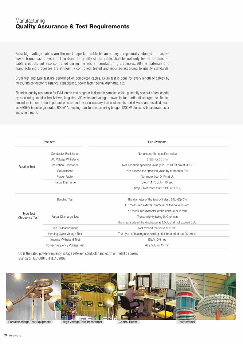
ManufacturingQuality Assurance & Test Requirements
Extra high voltage cables are the most important cable because they are generally adopted to massive power transmission system. Therefore the quality of the cable shall be not only tested for finished cable products but also controlled during the whole manufacturing processes. All the materials and manufacturing processes are stringently controlled, tested and reported according to quality standards.
Drum test and type test are performed on completed cables. Drum test is done for every length of cables by measuring conductor resistance, capacitance, power factor, partial discharge, etc.
Electrical quality assurance for D/M length test program is done for sampled cable, generally one out of ten lengths by measuring impulse breakdown, long-time AC withstand voltage, power factor, partial discharge, etc. Testing procedure is one of the important process and every necessary test equipments and devices are installed, such as 3600kV impulse generator, 600kV AC testing transformer, schering bridge, 1200kV dielectric breakdown tester and shield room.
Test Item Requirements
Routine Test
Type Test(Sequence Test)
Conductor Resistance
AC Voltage Withstand
Insulation Resistance
Capacitance
Power Factor
Partial Discharge
Bending Test
Partial Discharge Test
Tan & Measurement
Heating Cycle Voltage Test
Impulse Withstand Test
Power Frequency Voltage Test
Not exceed the specified value
2.5U0 for 30 min
Not less than specified value (þ:2.5 x 10¹⁵ ·cm at 20˚C)
Not exceed the specified value by more than 8%
Not more than 0.1% at U0
Step 1:1.75U0 for 10 sec
Step 2:Not more than 10pC at 1.5U0
The diameter of the test cylinder : 25(d+D)+5%
D : measured external diameter of the cable in mm
d : measured diameter of the conductor in mm
The sensitivity being 5pC or less
The magnitude of the discharge at 1.5U0 shall not exceed 5pC.
Not exceed the value 10x 10-4
The cycle of heating and cooling shall be carried out 20 times.
BIL/+10 times
At 2.5U0 for 15 min
U0 is the rated power-frequency voltage between conductor and earth or metallic screen.Standard : IEC 60840 & IEC 62067
Partialdischarge Test Equipment High Voltage Test Transformer Control Room Test terminal
24

Engineering
EngineeringSystem Design and Engineering Work
Cable System DesignMost of the extra high voltage cable projects include not only the manufacturing and supply of cables and accessories but also cable system design, civil works, cable laying, erection works, site testing and commissioning. A cable system should be designed to meet the user’s requirements in various respects in technology, economy, and stability. The design flow of cable system is shown in Chart 1.
Determining Cable SizeThe selection of conductor size depends on various system and installation conditions. The system conditions consist of required current ratings, rated system voltages, system frequency, short-circuit current and its duration, and so on. For the maximum current ratings, there are continuous current and emergency current. For the rated system voltages, there are nominal voltage, highest voltage, and basic impulse insulation voltage. The installation conditions consist of cable laying arrangements, laying methods, laying depth, soil thermal resistivity, ambient temperatures, other heat sources, and so on. For the cable laying arrangements, there are flat formation, trefoil formation and distances between phases and circuits. For the laying methods, there are directburial laying, in-duct laying, in-air laying and others.
Determining Sheath Bonding MethedCable sheaths are grounded by various methods. A solid bonding method presents the simplest solution. But the grounded sheaths produce large cable losses and, in turn, it largely reduces the power capacity of cable system. Special bonding methods are applied to reduce the cable losses. A single-point bonding method is applied in case of short route and less then two joints (see Figure 1), and a cross bonding method is applied in case of long route and many joints (see Figure 2). But these methods produce standing sheath-induced voltages, while the cable system shall be designed not to exceed the required maximum sheath voltage.
Determining Cable SpanSince cable products are produced at a certain length, cable jointing is required at a long cable route. Cable drum lengths and number of joints are determined generally on the various terms, cable manufacturing, transportation of drum, cable laying, cable system design and so on. In general, the followings are the most important terms to determine the maximum cable drum length.
25

Engineering
EngineeringSystem Design and Engineering Work
Review on User'sRequirement
Route Survey
Collecting DesignData
Determining Sheath Bonding Method
Selecting Cable Accessories
Calculating System Performance Data
Stady-stateCurrent Rating
EmergencyCurrent Rating
Short-CircuitCurrent Rating
ManufacturingCapability
Transportationin one Drum
Sheath BondingLimits
Cable PullingTension
DeterminingCable Span
Schematic LineDiagram
DeterminingCable Size
Fixing CableSystem
Chart 1.
1. Single Point Bonding SystemThis system is adopted for short length of the single core cable, generally without any joint, or circuit extension portion in addition to cross-bonding system. In this case, induced voltage on the metal layer cannot be diminished, therefore the system can be used, provided the induced voltage is less than dangerous level approximately 65V.
[V]Limitied Voltage Induced Sheath Voltage
Section Length
Bonding Leads
Solid Bond Link Box
Cable Conductor Cable Metallic Sheath
Cable Sealing End
Link Box With SVL's
SheathVoltageLimiters [SVL's]
2. Cross-Bonding SystemThis system is generally adopted for single core cable circuit having two or more joints. In the system, metallic layer of a cable is electrically separated(insulated) and connected to other cable's metallic layer at ends of every three section of the circuit, and then it will be connected to the another cable's layer. In the first section of the circuit, induced voltage is increased in proportion to cable length, but in the next section, it is decreased first time and increased again because induced voltages from two otherphase is mixed together in this section. In same reason, induced voltage at the end of this three section circuit becomes almost zero level remaining small amount of residual voltage due to unbalance of the joint section, etc.
[V] Limited Voltage
Minor Section Minor Section Minor SectionMajor Section
Induced Sheath Voltage
Bonding & Grounding Cable Cable Conductor Cable Metallic SheathInsulated Joint Normal Joint
Link Plate
Solid BondLink Box
Concentric Bonding LeadCross Bond Link Box
Sheath Voltage Limiter
26

Engineering
EngineeringInstallation
TAIHAN has many achievements and excellent techniques related to turnkey-base projects. The turnkey-base projects include the installation and engineering services as well as the supply of cable system. The quality of the cable system at the site depends mainly on cable laying work, and jointing and terminating works. TAIHAN has most qualified engineers and workers who are skillful and experienced in carrying out the installation works. Also TAIHAN has much experience on various cable laying methods. The followings are generally applied as a cable laying method.
Direct in the GroundThis method is shown in Fig.3, and is employed in following cases;
1) Where road is narrow so the construction of conduit under the road not permitted.2) Where the number of cables is few and nofuture increase is expected.3) Where the road digging is easy.
Underground Duct or TunnelThis method is shown in Fig. 4, 5, and is employed in following cases;
1) The case of main underground transmission line where the number of cables are many or expected to be increased in near future.2) The case of hard pavement or where hard pavement will be constructed in future.3) Where digging is difficult due to heavy traffic.
Special LayingIn case cables are installed in special places where there are bridges or railways, special laying methods are employed as follows;
1) When a cable crosses a river or canal, cables are attached to the bridge. If there is no suitable bridge in the neighborhood, an exclusive bridge should be built or a method of submarine laying should be adopted. As long as the strength and space of the bridge permits, it is best to attach the cables to the bridge. Whether it is better to build an exclusive bridge or to lay submarine cable depends on the cost and difficulty of construction.2) In case of crossing a railway, there are two methods; one is digging through the railway bed, and the other is piercing from the side of the railway by using an excavator, when the cable crosses many tracks like a surface from railroad or suburban railway, digging the railway bed is usually adopted. Except for the above case, piercing by using an excavator is adopted.
27

Engineering
EngineeringInstallation
Fig 3. Direct Burial
Fig. 4 Cable Laying at Duct
Fig. 5 Cable Laying at Tunnel
telephone
tension meter
pu l l i ng wire
pulling eyero l ler or caterpillar
caterpillar
power cable for caterpillar
cable drumoperator
telephonecontrol panel
caterpillar cable drum
Manholecable
power cable for caterpillar
pulling eyeDuct
winch car
Manhole
tension meter
control panel
caterpillarcable drum
Manhole
power cable for caterpillar
cable
telephone
pulling eye
Tunnelcaterpillar or roller
Manhole
28
operator
trough, if necessary
operator
pulling wire
pulling wire
Accessories
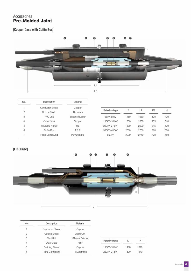
[FRP Case]
AccessoriesPre-Molded Joint
29
[Copper Case with Coffin Box]
No. Description Material
1
2
3
4
5
6
7
Conductor Sleeve
Corona Shield
PMJ Unit
Outer Case
Insulating Flange
Coffin Box
Filling Compound
Copper
Aluminum
Silicone Rubber
Copper
P.E
F.R.P
Polyurethane
Rated voltage L1
66kV~69kV
110kV~161kV
220kV~275kV
330kV~400kV
500kV
1150
1350
1800
2000
2000
L2 D1 H
1650
2300
2500
2750
2750
190
255
315
360
400
420
540
600
660
680
No. Description Material
1
2
3
4
5
6
Conductor Sleeve
Corona Shield
PMJ Unit
Outer Case
Earthing Sleeve
Filling Compound
Copper
Aluminum
Silicone Rubber
F.R.P
Copper
Polyurethane
H
310
370
Rated voltage L
110kV~161kV
220kV~275kV
1400
1800
L2
L1
D1H
L
H
Accessories
H
D
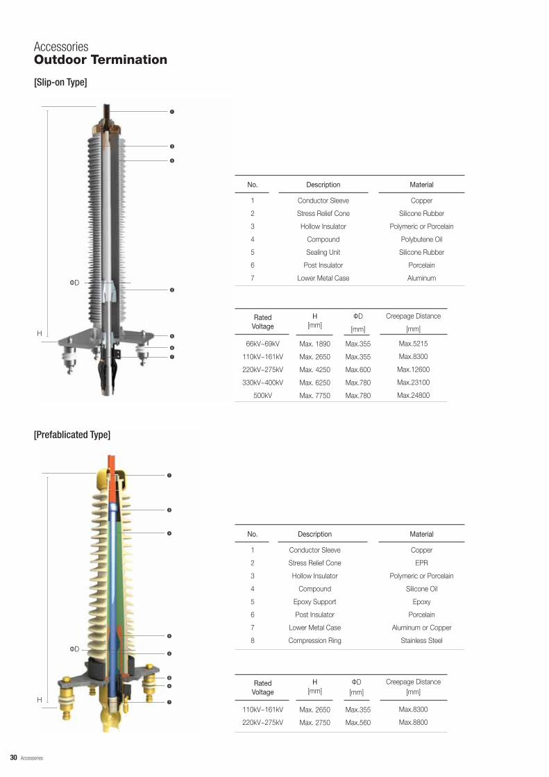
RatedVoltage
Creepage Distance
[mm]
66kV~69kV
110kV~161kV
220kV~275kV
330kV~400kV
500kV
Max.5215
Max.8300
Max.12600
Max.23100
Max.24800
D
[mm]
Max.355
Max.355
Max.600
Max.780
Max.780
H[mm]
Max. 1890
Max. 2650
Max. 4250
Max. 6250
Max. 7750
No. Description
1
2
3
4
5
6
7
Conductor Sleeve
Stress Relief Cone
Hollow Insulator
Compound
Sealing Unit
Post Insulator
Lower Metal Case
Material
Copper
Silicone Rubber
Polymeric or Porcelain
Polybutene Oil
Silicone Rubber
Porcelain
Aluminum
H
D
[Prefablicated Type]
RatedVoltage
Creepage Distance[mm]
110kV~161kV
220kV~275kV
Max.8300
Max.8800
D[mm]
Max.355
Max.560
H[mm]
Max. 2650
Max. 2750
No. Description
1
2
3
4
5
6
7
8
Conductor Sleeve
Stress Relief Cone
Hollow Insulator
Compound
Epoxy Support
Post Insulator
Lower Metal Case
Compression Ring
Material
Copper
EPR
Polymeric or Porcelain
Silicone Oil
Epoxy
Porcelain
Aluminum or Copper
Stainless Steel
AccessoriesOutdoor Termination
[Slip-on Type]
30

Accessories
No. Description
1
2
3
4
5
6
Upper Metal
Epoxy Bushing
Conductor Sleeve
Stress Relief Cone
Compression Ring
Lower Metal Case
Material
Aluminum
Epoxy
Copper
EPR
Stainless Steel
Copper or Aluminum
* All dimensions are complying with IEC60859 and IEC62271-209
RatedVoltage
66kV~88kV
110kV~161kV
220kV~275kV
330kV~400kV
D[mm]
110
110
200
250
H[mm]
583
757
960
1400
D[mm]
110
110
140
140
H[mm]
310
470
620
960
Fluid Filled type Dry Type
[Fluid Filled Type] [Dry Type]
H
DD
H
[Slip-on Type]
D[mm]
110
140
140
RatedVoltage
110kV~161kV
220kV~275kV
330kV~500kV
H[mm]
757
960
1400
Material
Aluminum
Epoxy
Copper
Silicone Rubber
Polybutene Oil
Silicone Rubber
Copper or Aluminum
No. Description
1
2
3
4
5
6
7
Upper Metal
Epoxy Bushing
Conductor Sleeve
Stress Relief Cone
Compound
Sealing Unit
Lower Metal Case
* All dimensions are complying with IEC60859 and IEC62271-209
H
D
AccessoriesSF6 Gas Insulated Termination
[Prefablicated Type]
31

Accessories
AccessoriesCOMPOSITE HOLLOW BUSHING
H
OD
H
OD
Taihan has been developing and producing composite hollow bushing which consists of FRP tube and silicone rubber sheds to withstand various environmental conditions. The advantage of composite bushing over traditional porcelain bushing has been proven and is well known and accepted.
ADVANTAGES Reduced Risk for transport and assembly (no broken sheds) Explosion Safety for personnel and installation Excellent Seismic Performance High Insulating Performance in highly polluted environment
APPLICATIONS Cable Terminations Circuit Breakers Instrument Transformers Lightning arrester
[Normal flange] [Cap flange]
RatedVoltage
110kV~161kV
220kV~275kV
5280
6720
8150
Max.9100
D[mm]
260
260
260
370
H[mm]
1676
2060
2444
2535
Creepage Distance [mm]
1495
1879
2263
Max.2308
Arcing Distance [mm] [mm]
378
378
378
505
* Other creepage distances are on request
32

Accessories
AccessoriesGIS EPOXY INSULATOR
Taihan has been manufacturing several kinds of cast epoxy insulators which are using in GIS systems. With our extensive knowledge regarding material technology with advanced process engineering skills, we have been developed and produced GIS insulator upto 800kV grade.
VACUUM CASTING TECHNOLOGY Void-free Insulation Excellent adhesion to metallic parts Net shape casting
PRODUCT Insulation Spacer Tri-post Insulator Earthing Terminal Insulation Supporter
[420kV × 1P Spacer]
[550kV × 1P Spacer]
[170kV × 3P Spacer]
[420kV Tri-Post Insulator ]
33

Diagnosis System
Diagnosis SystemCable Diagnosis System
DTS menuDetect cable fault symptom, and find out fault location as analyzing distributed temperature.
Alarm works for exceeding limitation of cable surface temperature, conductor temperature, conductor temperature 0deviation, temperature differences between joints, peaks, and cable permitted load. Malfunction of DTS are also sensed based on DTS temperature data.
Section can be set by operator to monitor whole cables separating them into several sections. These sections are usually divided depending on joints, but it’s flexible. Information for recent alarm is shown on the section table.
History menu supports operators to inquire temperature and alarm history data. Operator can choose cable surface temperature, conductor temperature, peaks as inquiry objects, and they are displayed on the chart. Alarm data are listed up at a table. The chart and table can be printed as an image and a table respectively, and they can be exported as an excel file.
1. Total Monitoring System (TMS)As a cable Total Monitoring System, TMS consists of three parts functionally, DTS system which can monitor distributed temperature of the cable, cable model data which includes thermal resistance and capacitance, and cable current value acquisition module. Menus of TMS are DCR, DTS, Alarm, Section, Setup, and History.
DCR menuIncrease efficiency of cable operation as calculating dynamic rating.How long current can be sustained from now on?
This cable can afford 2302[A] up to 8Hr.
8Hr
Input arbitrary current value, thenaffordable time is calculated.
Input arbitrary time, then affordablecurrent value is calculated.
Cable rating can be calculated Just with temperature data.
Cable system configuration
Data Summary Table
1) Location of Bottle Necks2) Cable Surface Temperature3) Cable Conductor Temperature4) Spatial Peak & Time Interval Peak
Bott le neck is the spot which has the highest cable surface temperature decides the cable rating, and it is updated every 1 hour for last 24 hours
34

Diagnosis System
Pulse Generator Spectrum Analyzer HFCT Sensor Foil SensorAmplifier Unit
2. PD (Partial Discharge) MeasurementPartial discharge is an incomplete breakdown of insulation and a kind of discharging phenomenon, which is generated by or at air-gap of solid insulator, gas foam of liquid insulator, contacting surfaces of different insulating materials and peaks on metallic surface. It is generated by the reason that as the permittivity of gas area is lower than that of solid or liquid, electric field is concentrated, and thus electric discharges occur in the gas due to the low dielectric strength of the gas.
1) Measurement MethodImpress an AC voltage of commercial cycle to a conductor to detect partial discharge of the insulator between the conductor and a shielding layer. And measure the starting electric charge and frequency of the partial discharge.
2) Analyzing Measurements
ICM System
(1) Main Components of PD Devices
Acquisition Unit / System Controller
(2) On-site PD Detection on EHV Cable (Insulation Joint)
(3) Patterns of PD Result
Void Discharge of Insulator Internal Discharge from a Joint Electric Tree of XLPE Cable
35

Diagnosis System
Diagnosis SystemCable Diagnosis System
(1) Main Components of PD Devices
PD Base System
Media ConverterPD Base Impedance Matching Box System Controller
Direct Coupler Calibrator Amplifier Unit Synchronization Sensor
(3) Patterns of PD Result
A. Resonant Test Set Induced DisturbanceB. Corona in HV Connections
C. Correlation Disturbance due to the Switching Devices of theAC Resonant Test SetD. HF Noise due to External SourcesE. PD from a Joint
36
(2)On-site PD Detection on EHV Cable (Termination)
3) Available Equipment
Equipment Manufacturer Purchasing Date Diagnosis Performances
ICMSystem
PD BaseSystem
Power Diagnostix(Germany)
TECHIMP(Italy)
2003/08
2005/07
· KEPCO (345kV Yeongseo -Yeongdeungpo T/L, 154kV Seongdong - Heungin T/L, 154KV Daejeon - Shinheung T/L, etc.)· Commercial Clients (Many sites including Korea LNG Gas)
· KEPCO (Many works including 154kV underground T/L in Central P/O of Seoul Electric Power)· Commercial Clients (Many sites including 230kV Singapore, 154kV Changwon Specialty Steel, 154kV Honam Thermal Power Plant and345kV Yangyang Pumping-up Power Plant)

Diagnosis System
3. Thermal infrared imaging measurement
1) Objects of Measurement
2) Measurement Cycle
3) Analyzing Measurement
4) Available Equipment
Equipment Manufacturer Purchasing Date Diagnosis Performances
Therma CAM™
QuickView
FLIR System(Sweden)
2004/01· KEPCO (345kV Yeongseo-Yeongdeungpo T/L, 154kV Seongdong - Heungin T/L, 154Kv Daejeon -Shinheung T/L, etc.)· Consigned patrol(Yeongseo, Seongdong and Daejeon ElectricPower)· Commercial Clients (Many sites including Korea LNG Gas, Changwon Specialty Steel, Yangyang Pumping-up Power Plant) <2 times of measurements a year>
Circuit Measurement
Thermal Infrared Imaging Measurement
4. Other Inspection & Measurements of XLPE Cable
Inspection & Measurement Items Method of Evaluation
Inspecting manhole/electric powerculvert (tray) and cable (on-line)
Inspecting metallic support & joint box (on-line)
Inspecting cable head (on-line)
Sheath Megger Test / withstandvoltage test (10kV) (off-line)
Inspecting fire detecting facility (online)
Partial discharge measurement(on-line / off-line)
Thermal infrared imaging measurement(on-line)
Locking Device of Exits, Installation state of ladder & guard rail, leakage & crack in electric power culvert, cleaning state of electric power culvert, prevention of disaster in electric power culvert, snake deformation of cable, prevention of disaster for cable, state of curvature, disorder of fire shielding plate
Deformation of metallic support, measuring current of metallic sheath, measuring temperature of joint box, measuring insulation resistance of anti-corrosion layer of cable, disorder of Cross-Bonding wire, water-tightness of anti-corrosion layer protecting device
Measuring temperature of overheated place for conductor joining part / PG clamp / lightening arrester joining part, measuring insulation resistance, Dobble Test
Joint places / cable
Fixed temperature detector, firefighting device, etc.
Joint places
Measuring image temperature with Thermal-vision/follow-up
37
* Inspection of power transmission facilities can be performed in on-line or off-line state according to the properties of a facility.

Appendix
APPENDIXCertification
The outstanding quality of TAIHAN EHV XLPE cables are verified by internationally accredited certification institutes.
Type Test Certificates over 132kV
1
2
3
4
5
6
7
8
9
10
11
12
13
14
15
16
17
18
19
20
21
22
23
24
25
No. BIL (kV)Description of Cable & Accessories InstituteDate
Cable, Premolded Straight Joint, Outdoor Termination
Cable
Cable
Cable
Cable
Cable, Outdoor Termination
Cable, NJ, IJ, Outdoor Termination
Cable, NJ, IJ, Outdoor Termination
Cable, PIJ, GIS & Outdoor Termination
Cable, NJ, IJ, Outdoor Termination
Cable, IJ, GIS Termination
Cable, PNJ, PIJ, GIS & Outdoor Termination
Cable, NJ, GIS & Outdoor Termination
Cable, PNJ, PIJ, GIS & Outdoor Termination
Cable, NJ, GIS & Outdoor Termination
Cable, PNJ, PIJ, GIS & Outdoor Termination
Cable, NJ, IJ, GIS & Outdoor Termination
Cable
Cable, IJ, GIS & Outdoor Termination
Cable, PIJ, GIS & Outdoor Termination
Cable, PMIJ, PMNJ, GIS & Outdoor Termination (Polymer type)
Cable, PIJ, GIS & Outdoor Termination
Cable
Cable, NJ
Cable
Specification Voltage Grade
KEMA
KERI
KERI
KERI
Crown Agents
Crown Agents
KERI
KERI
KEMA
KERI
Taihan
KEMA
Taihan
KERI
Taihan
KERI
KEMA
CTL(USA)
SGS
KERI
SGS
KEMA
Taihan
KERI
Taihan
May-86
May-86
Aug-86
Aug-88
May-95
May-96
May-97
Sep-97
Jun-98
Sep-99
Aug-00
Aug-00
Mar-01
Jun-01
Dec-03
Mar-04
Jan-05
Feb-05
Apr-05
Jul-05
Apr-05
Sep-05
Oct-05
Oct-05
Nov-06
IEC 502
KEPCO
KEPCO
KEPCO
IEC 840
IEC 840
KEPCO
KEPCO
IEC 840
KEPCO
IEC 62067
IEC 60840
IEC 60840KEPCO
IEC 62067IEC 60840
KEPCOIEC 62067IEC 62067
AEIC CS7-93
IEC 62067KEPCO
IEC 62067KEPCO
IEC 60840
IEC 60840
IEC 60840
IEC 60840
IEC 61901
132kV 630mm² (CU)
154kV 600mm² (CU)
154kV 1200mm² (CU)
154kV 2000mm² (CU)
132kV 1000mm² (CU)
132kV 630mm² (AL)
154kV 600mm² (CU)
154kV 2000mm² (CU)
230kV 2000mm² (CU)
154kV 2000mm² (CU)
132kV 630mm² (CU)
132kV 1200mm² (CU)
132kV 800mm² (AL)
345kV 2000mm² (CU)
132kV 630mm² (CU)
345kV 600mm² (CU)
400kV 2000mm² (CU)
138kV 1000mm² (CU)
230kV 2000mm² (CU)
345kV 1200mm² (CU)
154kV 2500mm² (CU) with fiber optic cable
132kV 1000mm² (CU)
132kV 1000mm² (CU)
132kV 630mm² (CU)
69kV 2500mm² (CU)
650
750
750
750
650
650
750
750
1050
750
650
650
650
1300
650
1300
1425
650
1050
1300
750
650
650
650
-
38

Appendix
* KERI : Korea Electrotechnology Research Institute * KEPCO : Korea Electricity Power Company( The National Power Utility in Korea) * POSCO : Pohang Steel Corporation
System Certificates
No. Description of Cable & Accessories Institute Date Specification
1
2
Design and manufacture of high voltageinsulators and cable joint accessories
Design and manufacture of electric cable
* SGS-ICS : Systems & Services Certification
39
26
27
28
29
30
31
32
33
34
35
36
37
38
39
40
41
42
43
44
45
46
47
48
49
50
51
52
53
54
55
56
57`
No. BIL (kV)Description of Cable & Accessories InstituteDate
Cable
Cable, PMJ, GIS & Outdoor Termination
Cable, NJ, Outdoor Termination, CONNEX Cable termination system (Size 4, Size 5S)
Cable, Cross Bonding Joint, Outdoor Termination
Cable, NJ, Straight Through Cross Bonking Joint
Cable, Straight Through Cross Bonking Joint, GIS & Outdoor TerminationPMJ
Cable, NJ, GIS & Outdoor Termination
Cable, IJ
Cable
Cable, PMIJ, PMNJ, PIJ, PNJ, GIS & Outdoor Termination
Cable, NJ, GIS Termination
Cable, NJ, GIS Termination
Cable, NJ, PMIJ, PMNJ, GIS & Outdoor Termination
Cable, PMIJ, Outdoor Termination
Cable, PNJ, GIS & Outdoor Termination
Cable, IJ, GIS & Outdoor Termination
Cable, PMIJ, GIS & Outdoor Termination, Oil Immersed Transformer Termination
Cable, PMIJ, PMNJ, GIS & Outdoor Termination
Cable, NJ, GIS & Outdoor Termination
Cable, PMJ, Outdoor Termination
Cable, NJ, GIS & Outdoor Termination, Cross-Bonding Link Box, Solid Link Box with Arrester, Solid Bonding Link Box without SVL's
Cable, IJ, NJ, GIS & Outdoor Termination
Cable, GIS & Outdoor Termination, Pre-Molded Type Cross Bonding Joint, Transformer Sealing End
Cable, PMJ, GIS & Outdoor Termination
Cable, IJ, NJ, GIS & Outdoor Termination
Cable, IJ, NJ, GIS & Outdoor Termination
Cable, NJ, Outdoor Termination
Cable, Outdoor Termination
Cable, PIJ, Outdoor Termination, SF6 Switchagear Sealing end (Oil Type, Dry Type), Transformer Termination (Oil Type, Dry Type)
Cable, GIS Termination, Pre-mold type straight insulated joint
Cable
Specification Voltage Grade
Taihan
KEMA
Taihan
Taihan
KEMA
KEMA
KEMA
KEMA
Taihan
KEMA
KERI
Taihan
Taihan
KERI
KERI
KERI
KEMA
KEMA
KERI
KEMA
Taihan
KEMA
KEMA
Taihan
Taihan
KEMA
KEMA
Taihan
Taihan
Taihan
Taihan
Taihan
Oct-05
Sep-06
Nov-06
Jan-07
Jan-07
May-07
Dec-07
Dec-07
Jul-07
Oct-07
Jul-08
Mar-08
May-08
Jun-09
Jun-09
Jun-09
Dec-09
Jul-09
Feb-10
Jan-10
Mar-10
Apr-10
May-10
Dec-10
Jul-10
Mar-11
Nov-10
Jan-11
Feb-11
May-11
Jul-11
Oct-11
IEC 60840
IEC 62067
IEC 60840
IEC 60840
IEC 60840
IEC 60840
IEC 62067
IEC 62067
IEC 60840
IEC 60840
KEPCO
IEC 60840
IEC 60840
IEC 60840
IEC 60840
IEC 60840
IEC 62027
IEC 60840
KEPCO
IEC 62027
IEC 60840
IEC 60840
IEC 62067AEIC CS9-06
IEC 62067
IEC 62067
IEC 62067
IEC 62067
IEC 62067
IEC 60840
IEC 60840
IEC 60840
IEC 60840
132kV 1000mm² (CU)
220kV 2500mm² (CU)
66kV 500mm² (CU)
132kV 1200mm² (CU)
132kV 630mm² (CU)
132kV 1200mm² (CU)
400kV
380kV 2500mm² (CU)
66kV 1000mm² (CU)
132kV 630mm² (CU)345kV 2500mm²(CU) with
fiber optic cable132kV 1600mm² (CU)
132kV 300mm² (CU)
132kV 2500mm² (CU)
275kV 2500mm² (CU)
220kV 2000mm² (CU)
400kV 2500mm² (Enamel - CU)
132kV 1000mm²
154kV 400mm² (CU) -17t
400kV 2500mm² (Enamel - CU)
132kV 1200 & 2000mm²
132kV 1200mm²
230kV 3500mm²
220kV 1200mm²
230kV 2000mm²
220kV1200mm² (AL)
500kV 2500mm²
230kV 1400mm² (AL)
138kV 1200mm²
132kV 630mm²
66kV 1000mm²
132kV 630mm²
IEC 60840
IEC 62067
IEC 60840
IEC 60840
IEC 60840
IEC 60840
IEC 62067
IEC 62067
IEC 60840
IEC 60840
KEPCO
IEC 60840
IEC 60840
IEC 60840
IEC 60840
IEC 60840
IEC 62027
IEC 60840
KEPCO
IEC 62027
IEC 60840
IEC 60840
IEC 62067AEIC CS9-06
IEC 62067
IEC 62067
IEC 62067
IEC 62067
IEC 62067
IEC 60840
IEC 60840
IEC 60840
IEC 60840
SGS-ICS
SGS-ICS
2001.02
2003.03
ISO 14001
ISO 9001

Appendix
Dubai Representative OfficeFlat No.1204, Al Safa Tower, Sheikh Zayed Road, P.O.Box 117561, Dubai, UAETEL : +971-4-331-7233 FAX : +971-4-331-7322E-mail : [email protected], [email protected]
Singapore Branch Office150 Kampong Ampat #07-04 KA Centre Singapore 368324,Republic of SingaporeTEL : +65-6842-5069 FAX : +65-6842-5076E-mail : [email protected]
Newzealand Branch Office
Suite 2, Level 11, 48 Emily Place, Auckland PO Box 105895,Auckland City, Auckland 1143TEL : +64-9-368-7703 FAX : +64-9 368-7704E-mail: [email protected]
Riyadh Branch OfficeOffice No.613, Al Rossais Commercial CenterOlaya Road, P.O.Box 300201, Riyadh 11372, Kingdom of Saudi ArabiaTEL : +966-1-419-0227 FAX : +966-1-419-0262E-mail : [email protected]
Qatar Branch OfficeDuhail Road Near College of North Atlantic P.O.Box : 18740 - Doha QatarTEL : +974-421-3851E-mail: [email protected]
Kuwait Branch OfficeSabah al Salem, block No.4, Street No.31 House No.7, State of KuwaitTEL : +965-2552-8642 FAX : +965-2552-1498E-mail : [email protected]
Kuala Lumpur Branch OfficeNo. 9, 2nd Floor, Jalan Pandan Prima 1 Dataran Pandan Prima 55100 Kuala Lumpur, MalaysiaTEL : +60-3-9018-9113/9115 FAX : +60-3-9200-1136E-mail : [email protected]
Overseas Branch Office
Overseas Subsidiaries
Subsidiary Company / Branch office
Hong Kong TGH (Taihan Global Holdings, Ltd.)
No.1808, 18F, Tower 2, Admiralty Center,18 Harcourt Road, Admiralty, Hong Kong
Australia Branch OfficeSuite 2, Level 13, 80 Mount Street, North Sydney, NSW 2060, AustraliaTEL : 61-2-9460-3600 FAX : 61-2-9954-4354E MAIL: [email protected]
Argentina Branch OfficeSuipacha Suites, Room 909 Suipacha 1235TEL : +54-911-6413-7430 FAX : 54-911-6413-4694 E MAIL : [email protected]
Venezuela Branch OfficeAvenida Principal Los Chorros de mila Centro Epresarial Villa Los ChorrosPiso4 Oficina 404 Merida, VenezuelaTEL : +58-274-414-1627E-mail : [email protected], [email protected]
South Africa Malesela Taihan Electric Cable Pty., Ltd. (M-TEC)
Steel Road Peacehaven Vereeniging 1930 Gauteng, South AfricaTEL : +27-16-450-8200 FAX : +27-16-450-8202E-mail : [email protected] : www.m-tec.co.za
D.R. Congo STANDARD TELECOM
158, Avenue de la Democratie(Ex- Huilerie) Commune de la Gombe, Kinshasa, D.R.CongoTEL : +243-1511-0007FAX : +243-1511-1100E-mail : [email protected] : www.st.cd
Vietnam Taihan Sacom Cable Co., Ltd (TSC)
7th Floor, 71-73 Dien Bien Phu, phuong 15, Binh Thanh District, VietnamTEL : +84-8-518-0786FAX : +84-8-518-0785E-mail : [email protected] : www.tsc.vn
USA Taihan USA (Taihan Electric USA., Ltd.)
LandMark Building, 99 Tulip Avenue, Suite#106, Floral Park, NY 11001, USATEL : +1-516-355-5600FAX : +1-516-355-5601E-mail : [email protected]
Qatar
New Zealand
APPENDIXGlobal Networks
40

Appendix 41

TPE-0501-1112