11 energy methods
DESCRIPTION
MOSTRANSCRIPT

MECHANICS OF
SOLIDS CHAPTER
GIK Institute of Engineering Sciences and Technology
11 Energy Methods

GIK Institute of Engineering Sciences and Technology
MECHANICS OF SOLIDS
11 - 2
Energy Methods
Strain Energy
Strain Energy Density
Elastic Strain Energy for Normal Stresses
Strain Energy For Shearing Stresses
Sample Problem 11.2
Strain Energy for a General State of Stress
Impact Loading
Example 11.06
Example 11.07
Design for Impact Loads
Work and Energy Under a Single Load
Deflection Under a Single Load
Sample Problem 11.4

GIK Institute of Engineering Sciences and Technology
MECHANICS OF SOLIDS
11 - 3
• A uniform rod is subjected to a slowly increasing load
• The elementary work done by the load P as the rod
elongates by a small dx is
which is equal to the area of width dx under the load-
deformation diagram.
workelementarydxPdU
• The total work done by the load for a deformation x1,
which results in an increase of strain energy in the rod.
energystrainworktotaldxPU
x
1
0
11212
121
0
1
xPkxdxkxU
x
• In the case of a linear elastic deformation,
Strain Energy

GIK Institute of Engineering Sciences and Technology
MECHANICS OF SOLIDS
11 - 4
Strain Energy Density
• To eliminate the effects of size, evaluate the strain-
energy per unit volume,
densityenergy straindu
L
dx
A
P
V
U
x
x
1
1
0
0
• As the material is unloaded, the stress returns to zero
but there is a permanent deformation. Only the strain
energy represented by the triangular area is recovered.
• Remainder of the energy spent in deforming the material
is dissipated as heat.
• The total strain energy density resulting from the
deformation is equal to the area under the curve to 1.

GIK Institute of Engineering Sciences and Technology
MECHANICS OF SOLIDS
11 - 5
Strain-Energy Density
• The strain energy density resulting from
setting 1 R is the modulus of toughness.
• The energy per unit volume required to cause
the material to rupture is related to its ductility
as well as its ultimate strength.
• If the stress remains within the proportional
limit,
E
EdEu x
22
21
21
0
1
1
• The strain energy density resulting from
setting 1 Y is the modulus of resilience.
resilience of modulusE
u YY
2
2

GIK Institute of Engineering Sciences and Technology
MECHANICS OF SOLIDS
11 - 6
Elastic Strain Energy for Normal Stresses
• In an element with a nonuniform stress distribution,
energystrain totallim0
dVuU
dV
dU
V
Uu
V
• For values of u < uY , i.e., below the proportional
limit,
energy strainelasticdVE
U x 2
2
• Under axial loading, dxAdVAPx
L
dxAE
PU
0
2
2
AE
LPU
2
2
• For a rod of uniform cross-section,

GIK Institute of Engineering Sciences and Technology
MECHANICS OF SOLIDS
11 - 7
Elastic Strain Energy for Normal Stresses
I
yMx
• For a beam subjected to a bending load,
dVEI
yMdV
EU x
2
222
22
• Setting dV = dA dx,
dxEI
M
dxdAyEI
MdxdA
EI
yMU
L
L
A
L
A
0
2
0
22
2
02
22
2
22
• For an end-loaded cantilever beam,
EI
LPdx
EI
xPU
PxM
L
62
32
0
22

GIK Institute of Engineering Sciences and Technology
MECHANICS OF SOLIDS
11 - 8
Strain Energy For Shearing Stresses
• For a material subjected to plane shearing
stresses,
xy
xyxy du
0
• For values of xy within the proportional limit,
GGu
xyxyxyxy
2
2
212
21
• The total strain energy is found from
dVG
dVuU
xy
2
2

GIK Institute of Engineering Sciences and Technology
MECHANICS OF SOLIDS
11 - 9
Strain Energy For Shearing Stresses
J
Txy
dVGJ
TdV
GU
xy
2
222
22
• For a shaft subjected to a torsional load,
• Setting dV = dA dx,
L
L
A
L
A
dxGJ
T
dxdAGJ
TdxdA
GJ
TU
0
2
0
22
2
02
22
2
22
• In the case of a uniform shaft,
GJ
LTU
2
2

GIK Institute of Engineering Sciences and Technology
MECHANICS OF SOLIDS
11 - 10
Sample Problem 11.2
a) Taking into account only the normal
stresses due to bending, determine the
strain energy of the beam for the
loading shown.
b) Evaluate the strain energy knowing
that the beam is a W10x45, P = 40
kips, L = 12 ft, a = 3 ft, b = 9 ft, and E
= 29x106 psi.
SOLUTION:
• Determine the reactions at A and B
from a free-body diagram of the
complete beam.
• Integrate over the volume of the
beam to find the strain energy.
• Apply the particular given
conditions to evaluate the strain
energy.
• Develop a diagram of the bending
moment distribution.

GIK Institute of Engineering Sciences and Technology
MECHANICS OF SOLIDS
11 - 11
Sample Problem 11.2
SOLUTION:
• Determine the reactions at A and B
from a free-body diagram of the
complete beam.
L
PaR
L
PbR BA
• Develop a diagram of the bending
moment distribution.
vL
PaMx
L
PbM 21

GIK Institute of Engineering Sciences and Technology
MECHANICS OF SOLIDS
11 - 12
Sample Problem 11.2
vL
PaM
xL
PbM
2
1
BD,portion Over the
AD,portion Over the
43 in 248ksi1029
in. 108in. 36a
in. 144kips45
IE
b
LP
• Integrate over the volume of the beam to find
the strain energy.
baEIL
baPbaab
L
P
EI
dxxL
Pa
EIdxx
L
Pb
EI
dvEI
Mdx
EI
MU
ba
ba
2
2223232
2
2
0
2
0
2
0
22
0
21
6332
1
2
1
2
1
22
EIL
baPU
6
222
in 144in 248ksi 10296
in 108in 36kips4043
222
U
kipsin 89.3 U

GIK Institute of Engineering Sciences and Technology
MECHANICS OF SOLIDS
11 - 13
Strain Energy for a General State of Stress
• Previously found strain energy due to uniaxial stress and plane
shearing stress. For a general state of stress,
zxzxyzyzxyxyzzyyxxu 21
• With respect to the principal axes for an elastic, isotropic body,
distortion todue 12
1
change volume todue 6
21
22
1
222
2
222
accbbad
cbav
dv
accbbacba
Gu
E
vu
uu
Eu
• Basis for the maximum distortion energy failure criteria,
specimen test tensileafor 6
2
Guu Y
Ydd

GIK Institute of Engineering Sciences and Technology
MECHANICS OF SOLIDS
11 - 14

GIK Institute of Engineering Sciences and Technology
MECHANICS OF SOLIDS
11 - 15

GIK Institute of Engineering Sciences and Technology
MECHANICS OF SOLIDS
11 - 16

GIK Institute of Engineering Sciences and Technology
MECHANICS OF SOLIDS
11 - 17
Impact Loading
• Consider a rod which is hit at its
end with a body of mass m moving
with a velocity v0.
• Rod deforms under impact. Stresses
reach a maximum value m and then
disappear.
• To determine the maximum stress m
- Assume that the kinetic energy is
transferred entirely to the
structure,
202
1 mvUm
- Assume that the stress-strain
diagram obtained from a static test
is also valid under impact loading.
dVE
U mm
2
2
• Maximum value of the strain energy,
• For the case of a uniform rod,
V
Emv
V
EUmm
202

GIK Institute of Engineering Sciences and Technology
MECHANICS OF SOLIDS
11 - 18
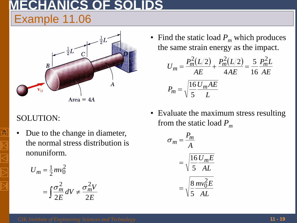
Example 11.06
Body of mass m with velocity v0 hits
the end of the nonuniform rod BCD.
Knowing that the diameter of the
portion BC is twice the diameter of
portion CD, determine the maximum
value of the normal stress in the rod.
SOLUTION:
• Due to the change in diameter, the
normal stress distribution is nonuniform.
• Find the static load Pm which produces
the same strain energy as the impact.
• Evaluate the maximum stress
resulting from the static load Pm
GIK Institute of Engineering Sciences and Technology
MECHANICS OF SOLIDS
11 - 19
Example 11.06
SOLUTION:
• Due to the change in diameter,
the normal stress distribution is
nonuniform.
E
VdV
E
mvU
mm
m
22
22
202
1
• Find the static load Pm which produces
the same strain energy as the impact.
L
AEUP
AE
LP
AE
LP
AE
LPU
mm
mmmm
5
16
16
5
4
22 222
• Evaluate the maximum stress resulting
from the static load Pm
AL
Emv
AL
EU
A
P
m
mm
20
5
8
5
16

GIK Institute of Engineering Sciences and Technology
MECHANICS OF SOLIDS
11 - 20
Example 11.07
A block of weight W is dropped from a
height h onto the free end of the
cantilever beam. Determine the
maximum value of the stresses in the
beam.
SOLUTION:
• The normal stress varies linearly along
the length of the beam as across a
transverse section.
• Find the static load Pm which produces
the same strain energy as the impact.
• Evaluate the maximum stress
resulting from the static load Pm

GIK Institute of Engineering Sciences and Technology
MECHANICS OF SOLIDS
11 - 21
Example 11.07
SOLUTION:
• The normal stress varies linearly
along the length of the beam as
across a transverse section.
E
VdV
E
WhU
mm
m
22
22
• Find the static load Pm which produces
the same strain energy as the impact.
For an end-loaded cantilever beam,
3
32
6
6
L
EIUP
EI
LPU
mm
mm
• Evaluate the maximum stress
resulting from the static load Pm
22
66
cIL
WhE
cIL
EU
I
LcP
I
cM
m
mmm

GIK Institute of Engineering Sciences and Technology
MECHANICS OF SOLIDS
11 - 22
Design for Impact Loads
• For the case of a uniform rod,
V
EUmm
2
V
EU
VLcccLcIL
cIL
EU
mm
mm
24
//
6
412
4124
412
2
• For the case of the cantilever beam
Maximum stress reduced by:
• uniformity of stress
• low modulus of elasticity with
high yield strength
• high volume
• For the case of the nonuniform rod,
V
EU
ALLALAV
AL
EU
mm
mm
8
2/52/2/4
5
16
GIK Institute of Engineering Sciences and Technology
MECHANICS OF SOLIDS
11 - 23

GIK Institute of Engineering Sciences and Technology
MECHANICS OF SOLIDS
11 - 24
Work and Energy Under a Single Load
• Previously, we found the strain
energy by integrating the energy
density over the volume.
For a uniform rod,
AE
LPdxA
E
AP
dVE
dVuU
L
22
2
21
0
21
2
• Strain energy may also be found from
the work of the single load P1,
1
0
x
dxPU
• For an elastic deformation,
11212
121
00
11
xPxkdxkxdxPU
xx
• Knowing the relationship between
force and displacement,
AE
LP
AE
LPPU
AE
LPx
2
211
121
11

GIK Institute of Engineering Sciences and Technology
MECHANICS OF SOLIDS
11 - 25
Work and Energy Under a Single Load
• Strain energy may be found from the work of other types
of single concentrated loads.
EI
LP
EI
LPP
yPdyPU
y
63
321
31
121
1121
0
1
• Transverse load
EI
LM
EI
LMM
MdMU
2
211
121
1121
0
1
• Bending couple
JG
LT
JG
LTT
TdTU
2
211
121
1121
0
1
• Torsional couple

GIK Institute of Engineering Sciences and Technology
MECHANICS OF SOLIDS
11 - 26
Deflection Under a Single Load
• If the strain energy of a structure due to a
single concentrated load is known, then the
equality between the work of the load and
energy may be used to find the deflection.
lLlL BDBC 8.06.0
From statics,
PFPF BDBC 8.06.0
From the given geometry,
• Strain energy of the structure,
AE
lP
AE
lP
AE
LF
AE
LFU BDBDBCBC
2332
22
364.02
8.06.0
22
• Equating work and strain energy,
AE
Ply
yPAE
LPU
B
B
728.0
364.021
2

GIK Institute of Engineering Sciences and Technology
MECHANICS OF SOLIDS
11 - 27
Sample Problem 11.4
Members of the truss shown consist of
sections of aluminum pipe with the
cross-sectional areas indicated. Using
E = 73 GPa, determine the vertical
deflection of the point E caused by the
load P.
SOLUTION:
• Find the reactions at A and B from a
free-body diagram of the entire truss.
• Apply the method of joints to
determine the axial force in each
member.
• Evaluate the strain energy of the
truss due to the load P.
• Equate the strain energy to the work
of P and solve for the displacement.

GIK Institute of Engineering Sciences and Technology
MECHANICS OF SOLIDS
11 - 28
Sample Problem 11.4
SOLUTION:
• Find the reactions at A and B from a free-body
diagram of the entire truss.
821821 PBPAPA yx
• Apply the method of joints to determine the
axial force in each member.
PF
PF
CE
DE
815
817
0
815
CD
AC
F
PF
PF
PF
CE
DE
821
45
0ABF

GIK Institute of Engineering Sciences and Technology
MECHANICS OF SOLIDS
11 - 29
Sample Problem 11.4
• Evaluate the strain energy of the
truss due to the load P.
2
22
297002
1
2
1
2
PE
A
LF
EEA
LFU
i
ii
i
ii
• Equate the strain energy to the work by P
and solve for the displacement.
9
33
2
21
1073
1040107.29
2
2970022
E
E
E
y
E
P
PP
Uy
UPy
mm27.16Ey
GIK Institute of Engineering Sciences and Technology
MECHANICS OF SOLIDS
11 - 30