11. annexure septic tank
DESCRIPTION
sewerageTRANSCRIPT

1
SEPTIC TANK CONSTRUCTION GUIDELINES
Septic tank for this airport will be designed/ built by the general contractor of the building
facilities.
At the time of the project design, availability of a septic tank obtained in market in this
region was not clear. Thus, the general contractor is given a choice of either proposing a
septic tank available in market or design/build one on site by themselves. Consultant strongly
recommends an in-situ concrete septic tank built at site based on the guidelines written
here-under. If the general contractor choose the market available product, a professional
engineer with certified credentials will be required to present the product to the Resident
Engineer and the Consultant with necessary drawings/documents to obtain their approvals
prior to the construction.
The target values of the septic tank treatment shall be as follows;
BOD elimination rate: 90% and over
BOD of the treated water: 20mg/L and less
General Provisions
1. There will be no structural failure or undue distortion under pressure when either full or
empty and be protected from, or designed to withstand, loadings imposed by vehicles,
buildings, soil and or ground waters and the internal loadings,
2. Septic tank will be watertight and retain structural integrity during transportation,
installation and operation,
3. Septic tanks shall be divided into two chambers so that the effective capacity of the first
chamber is twice that of the second chamber,
4. Length to width ratio is not less than 2:1 and a length to depth ratio of approximately 2:1,
5. Effective liquid depth is not less than 900mm,
6. Where required, the dividing partition wall shall be provided with transfer openings
centrally located within the liquid depth and be equally spaced from the vertical axis centre
line and the external wall,
7. Connections to the septic tank shall be such that they permit standard solvent welded joints
or rubber ring joints and enable the inlet and outlet pipe to be installed at grade,
8. Connections for the inlet, outlet and inspection openings are integrally cast for concrete
constructed septic tanks, and for plastic type materials the connections are to be
mechanically and/or chemically sealed or bonded so as to be water-tight and have a strength
equal to that of the parent material,
9. Where the inlet, outlet and inspection opening fittings for plastic type septic tanks are
permitted to be installed at the place of installation they shall be provided with fixing
mechanisms and clear instructions to prevent incorrect installation with regard to grade and
reversal of the inlet and outlet fittings.
2
Design for cast in situ concrete septic tank
1. The tank shall be structurally sound, smooth internally, watertight and the concrete shall
have a compressive strength of not less than 25 MPa (260kg/cm2, FC=25) at 28 days.
Approved construction details
Effective tank capacity:
Dimensions in mm: L: 6000, W: 3000, H: 2000
Reinforcement: Double 13mm dia. reinforcing steel bars @200mm for wall, cover and
floor, additional diagonal reinforcement at all openings
Concrete thickness mm: 200mm or more
2. Water level of the septic tank should be lower than the ground level by 900mm.
3. Rigid insulation should be applied to the top cover of the tank (made easy to remove for
maintenance) if 900mm of the No.2 requirement, above, not to be incorporated
4. All reinforcement is placed centrally
5. Septic tank should not be subject to any vehicular traffic loading
NOTE: For installation of cast in situ septic tanks not in accordance with the data above; or
subject to vehicle loadings; approval is required from the Resident Engineer and will need to
be supported with detail drawings, engineering calculations, material and construction
specifications and comply with the general provision. Any plan must be presented by a
registered professional engineer with the professional background accepted by the Resident
Engineer prior to the presentation.
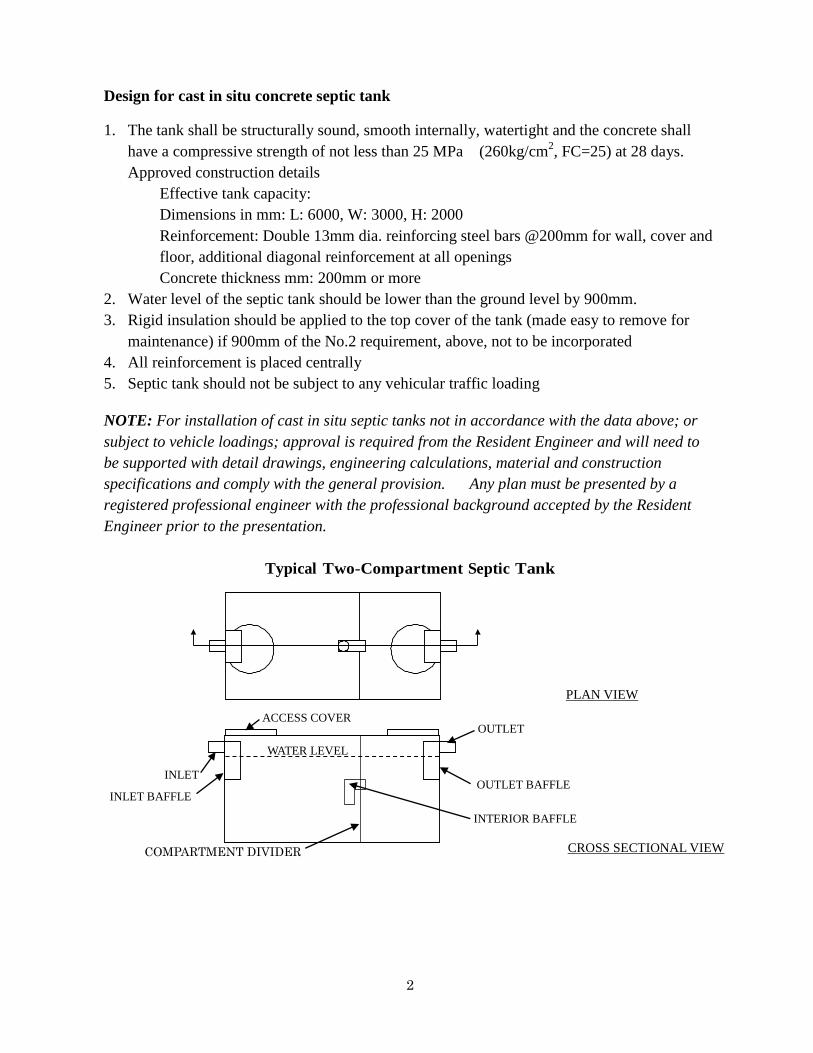
Typical Two-Compartment Septic Tank
WATER LEVEL
ACCESS COVER OUTLET
OUTLET BAFFLE
INTERIOR BAFFLE
COMPARTMENT DIVIDER
INLET
INLET BAFFLE
PLAN VIEW
CROSS SECTIONAL VIEW

3
Baffles are located at the inlet, compartment divider and outlet of a septic tank. The inlet baffle
is designed to slow down the incoming wastewater and direct it downward. The interior baffle
keeps most of the solid material in the first compartment and the outlet baffle retains the
lightweight floating material, such as grease and wax, within the tank, keeping it out of the soil
absorption field. A built-in vertical drop of approximately 80 mm between the inlet and outlet
pipe is common. During installation, if the inlet and outlet ends of the septic tank are reversed,
water will back up into the building sewer, stranding solids that could block the line. Septic
tanks should be pumped when the sludge layer or floating scum layer exceeds 150 mm. The
sludge and scum layer may be checked by using a clear plastic pipe with a foot valve. This pipe
is dipped down into the tank and upon removal visually shows sludge and scum depths. Septic
tanks must be periodically vacuum pumped. If septic tanks are not pumped periodically,
accumulated sludge will overflow with the wastewater into the soil absorption field, resulting in
premature failure of the field. The single most important maintenance item is to vacuum
pump a septic tank every two years.
Soil Absorption Design
Soil absorption system must be designed based on site specific information.
Required site information consists of:
· Sub surface soil conditions and percolation rate of the receiving soil
· Depth to the seasonal high ground water table
· Location of topographical features such as steep slopes, gullies, surface
water and existing nearby sewer systems
· Location of all nearby drinking water wells and determining the well
classification, whether
· Location of permafrost or impermeable soil bedrock
· Lot layout and any limitinig plat notes that may affect the type of onsite
system allowed.
Absorption Field
Once an absorption system is put into operation, a clogging mat or zone forms at the
infiltrative surface, which slows the movement of water into soil. Many factors, some
of which can be prevented by taking proper precautions during construction, contribute
to the development of a clogging mat. Compaction of the receiving soil and smearing
of the infiltrative surface are probably the two most significant errors made during
construction that leads to the development of the clogging mat.
Construction machinery should not be driven over the infiltrative area. Beds and
trenches should be excavated using a backhoe or similar apparatus, not using a dozer. If
during the excavation process, the infiltrative surface becomes smeared, the surface
should be raked or otherwise roughened, to remove the smeared soils. To overcome the
smearing that naturally occurs when a backhoe bucket is drawn through soil, some
4
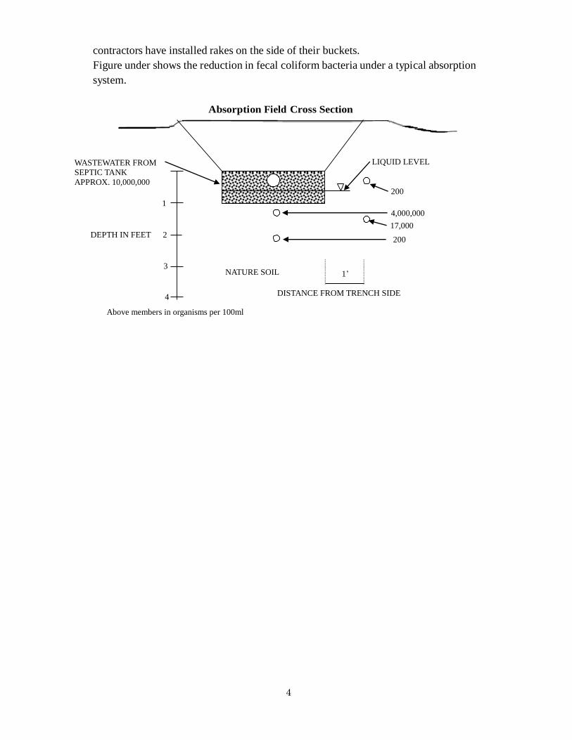
contractors have installed rakes on the side of their buckets.
Figure under shows the reduction in fecal coliform bacteria under a typical absorption
system.
Absorption Field Cross Section
LIQUID LEVEL
200
4,000,000
17,000
200
DISTANCE FROM TRENCH SIDE
NATURE SOIL
1
2
3
4
1’
WASTEWATER FROM
SEPTIC TANK
APPROX. 10,000,000
DEPTH IN FEET
Above members in organisms per 100ml
5
Sizing the absorption field
After selecting the most appropriate type of absorption system for a given site, the
infiltrative surface is sized based on soil conditions. Recognizing soil conditions and
accurately rating the absorption capacity of the soils is vital to the design of a good system.
At least two prospective areas should be investigated.
Pump Station
The original design does not include any pump station between the buildings and the septic
tank. However, in the course of construction, there could be a chance of such a facility need
might arise.
Most septic systems rely on gravity to sustain flow through the system. This requires the
septic
tank inlet to be lower than the building drain and the absorption area to be lower than the
septic tank outlet. Occasionally, site conditions prohibit a gravity flow installation, because
either the septic tank or the absorption area must be placed higher than the building drain.
In these cases, an appropriate pump must be used to lift the sewage or septic tank effluent to
the required elevation.
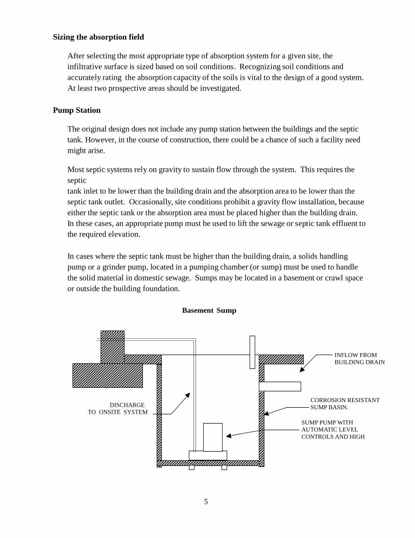
In cases where the septic tank must be higher than the building drain, a solids handling
pump or a grinder pump, located in a pumping chamber (or sump) must be used to handle
the solid material in domestic sewage. Sumps may be located in a basement or crawl space
or outside the building foundation.
Basement Sump
INFLOW FROM
BUILDING DRAIN
CORROSION RESISTANT
SUMP BASIN.
SUMP PUMP WITH
AUTOMATIC LEVEL
CONTROLS AND HIGH
DISCHARGE
TO ONSITE SYSTEM
6
All components must be made from corrosion resistant material and have a sealed
cover. All connections must be water-tight. Because raw sewage contains large
solids, a submersible grinder pump or a properly sized solids handling centrifugal
pump, capable of passing 50mm minimum or larger solids must be used. Grinder
pumps may be used that has cutting blades that grind solids to a size not clogging
the pump or piping.
The liquid level in the basin is usually controlled by a float switch that
automatically cycles the pump when a pre-set liquid level is reached. Many pump
manufacturers offer a complete packaged basin with pump, controls and a high level
alarm. A pump must be selected that is capable of meeting the total dynamic head
requirements of the system (elevation change, pipe friction loss and energy losses).
All pumping systems must conform to the requirements of the Uniform Plumbing
Code and contain a high level alarm.
Pumping systems handling raw sewage should be avoided whenever possible, by
adjusting the house elevation or the onsite system elevation during the planning
stages.
Minimum Construction Requirements
(Items to be discussed with Resident Engineer prior to the construction.)
1. Mechanical watertight couplings, such as Caulder coupling, Fernco
coupling, or equivalent are required on the inlet, outlet, and cleanout
(vent) pipes of septic tanks. Manhole covers must also be watertight.
2. The Wastewater Treatment and Disposal Regulations require that septic
tanks have two compartments.
3. Solid pipe with no joints should span 3m from the inlet and outlet of septic
tanks onto undisturbed earth.
7
4. Pressure distribution should be provided on all elevated bed and mound
systems.
Systems that employ pressure distribution must be designed by a registered
Engineer and approved in writing by Resident Engineer prior to construction.
5. A barrier of geo-textile filter fabric is always required on top of the sewer rock
to prevent soil backfill from migrating into the distribution rock.
6. 30 mm of approved insulation may be substituted for 360 mm of soil cover. If
adequate insulation is used, the soil cover depth may be reduced to 600 mm.
7. When side walls have smearing (glazing) evident, an alternate strata should be
used or a soil test by a professional engineer registered in Alaska can be
performed to determine the soils absorption ability.
8. On sloping lots, leach lines should traverse the slope.
9. Avoid compaction of soil strata to be used for absorption.
10. A foundation cleanout is required by the Uniform Plumbing Code.
11. Perforated pipes in the absorption bed, septic tanks, trench, bed, and pit
bottoms must be level. Septic tanks and solid piping must be laid on
undisturbed or properly compacted soils. Soil in the pipe zone should be
compacted to adequately protect the pipe from excessive deflections.
12. A cleanout is required ahead of the septic tank anytime a bend of 45
degrees or more is used.
13. Excavations should not be left open in order to prevent freeze-up or an unsafe
situation.
Design and Construction will be in line the below guidelines.
www.aed.usace.army.mil/contracting/AED-Design.pdf