108050000-td0010-r00 - oak ridge national … · web viewfault indicator light on mcc ready...
TRANSCRIPT
108050000-TD8023-R00
Spallation Neutron Source
Site Utilities Potable Water SystemFunctional System Design (FSD)
January, 2003
_______________________ SNS Project Engineer

Site Utilities Potable Water System Controls DescriptionTD8023 Rev 0, January 13, 2003
Operating Philosophy
Purpose:
The purpose of the potable water system operation is to:
a) Maintain the tower water at an appropriate level by energizing/de-energizing the three booster pumps.
b) Provide alarms for pump failures, low or high level conditions, low or high pressures, or loss of power.
c) Track pump run time to equalize pump utilization when starting and stopping pumps.
Assumptions: A maximum of 2 pumps will be running at any one time. The third pump is used for a backup in case of failure of one of the other two pumps.
Operator Controls and Operating Modes1) Restart Time Delay – This value determines the number of seconds after a power loss of
greater than 1 second before restarting the pumps. If multiple pumps are required, there is a 10 second delay after starting the first pump before the second pump is started.
2) Off – Booster pumps will be de-energized.3) Auto – Booster pumps will be automatically started and stopped as required to maintain
water tank level. When starting a booster pump, the available pump with the minimum amount of runtime will be started. When stopping a booster pump, the pump with the maximum amount of runtime will be stopped.
OPERATOR INTERFACE DEFINITIONS
Local Hardware/Manual Operator Controls1) Tank water pressure (PI 5701)2) HOA switch for Pump 1 (HS5701)3) HOA switch for Pump 2 (HS5702)4) HOA switch for Pump 3 (HS5703)5) FAULT indicator light on MCC6) READY indicator light on MCC7) RUN indicator light on MCC
Software HMI/EPICS Digital Operator Controls1) Booster Pump Control Mode
a. OFF (default) (XX5700TMO)b. AUTO (XX5700TMA)
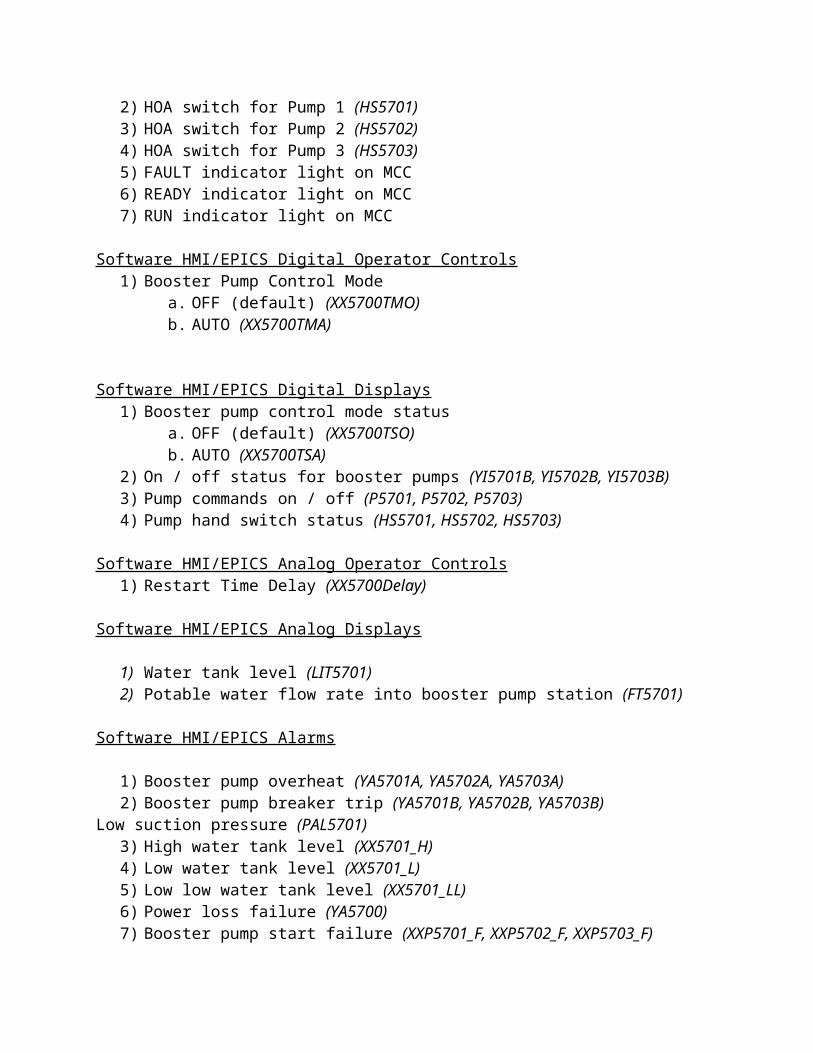
Software HMI/EPICS Digital Displays1) Booster pump control mode status
a. OFF (default) (XX5700TSO)b. AUTO (XX5700TSA)
2) On / off status for booster pumps (YI5701B, YI5702B, YI5703B)3) Pump commands on / off (P5701, P5702, P5703)4) Pump hand switch status (HS5701, HS5702, HS5703)
Software HMI/EPICS Analog Operator Controls1) Restart Time Delay (XX5700Delay)
Software HMI/EPICS Analog Displays
1) Water tank level (LIT5701)2) Potable water flow rate into booster pump station (FT5701)
Software HMI/EPICS Alarms
1) Booster pump overheat (YA5701A, YA5702A, YA5703A)2) Booster pump breaker trip (YA5701B, YA5702B, YA5703B)3) Low suction pressure (PAL5701)4) High water tank level (XX5701_H)5) Low water tank level (XX5701_L)6) Low low water tank level (XX5701_LL)7) Power loss failure (YA5700)8) Booster pump start failure (XXP5701_F, XXP5702_F, XXP5703_F)
Control Logic Description
In the OFF mode, the water tank booster pumps will be de-energized and the booster pump control mode status will be set to OFF.
In AUTO mode, the water tank booster pumps will be automatically started and stopped and the pump runtime hours accumulated as follows:
If the water tank level is between 29.5 and 28 feet, one pump will be started. The pump to start will be decided based on the hand switch being in auto and the minimum amount of run time hours. If the pump fails to return a “run” status within 10 seconds, the pump will be de-energized, an alarm set, and the backup pump will be energized. The backup pump will be determined by the hand switch being in auto and the minimum amount of run time hours. The backup pump will be checked for failure after 10 seconds. This process will continue until all pumps have been tried or a pump successfully returns the “on” status.
If the water tank level is below 27 feet, two pumps will be started. The pumps to start will be based on the hand switch being in auto and the minimum amount of run time
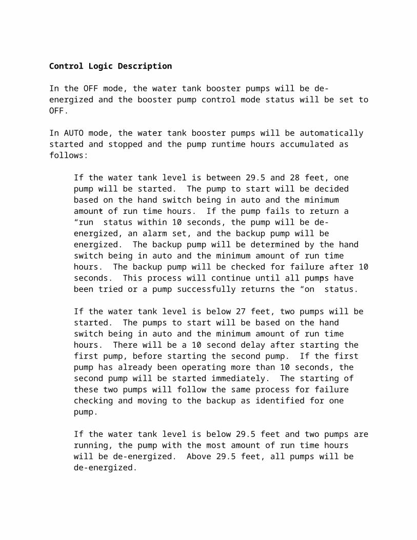
hours. There will be a 10 second delay after starting the first pump, before starting the second pump. If the first pump has already been operating more than 10 seconds, the second pump will be started immediately. The starting of these two pumps will follow the same process for failure checking and moving to the backup as identified for one pump.
If the water tank level is below 29.5 feet and two pumps are running, the pump with the most amount of run time hours will be de-energized. Above 29.5 feet, all pumps will be de-energized.
If the water tank level is above 30 feet, the high water tank level alarm will be activated. If the water tank level is below 17.5 feet, the low low water tank level alarm will be activated. If the water tank level is below 26 feet and above 17.5 feet, the low water tank level will be activated.
If a power loss is detected for less than 1 second, operation of the pumps will continue as normal. However, if the power loss is longer than 1 second, the pumps will be de-energized. Once the power has been restored, the pumps will be started (if needed) after the restart time delay specified by the operator. If multiple pumps are required, the second pump will be started 10 seconds after starting the first pump. The same failure checks will be performed when starting the pumps after a power loss.