10.4.1 - continuous beam i
DESCRIPTION
aTRANSCRIPT
2/18/13 Previous | Next | Contents
www.fgg.uni-lj.si/kmk/esdep/master/wg10/l0410.htm#SEC_1 1/17
Previous | Next | Contents
ESDEP WG 10
COMPOSITE CONSTRUCTION
Lecture 10.4.1: Continuous Beams I
OBJECTIVE/SCOPE
To describe the behaviour of continuous composite beams; to explain the use of rigid-plastic analysis to
determine internal moments and forces, and to derive plastic resistance moments.
PREREQUISITES
Lecture 7.2: Cross-Section Classification
Lecture 7.3: Local Buckling
Lecture 10.2: The Behaviour of Beams
Lecture 10.3: Single Span Beams
RELATED LECTURES
Lecture 10.4.2: Continuous Beams II
Lectures 10.5: Design for Serviceability
Lectures 10.6: Shear Connection
SUMMARY
The advantages of continuous beams are summarised and failure modes which result from continuity in composite
beams are identified. Plastic methods may be used to determine internal moments and forces, provided thatrotation capacity is sufficient and lateral-torsional buckling does not occur. The scope for plastic methods is
related to classification of cross-sections in terms of limiting breadth/thickness ratios for structural steel elements
in compression. Other measures needed to ensure adequate rotation capacity are also described. Simple values
for effective width of the concrete flange are presented and expressions for the negative resistance moment of
Class 1 and Class 2 sections are given. The application of rigid-plastic analysis to determine the distribution of
bending moments is demonstrated.
1. INTRODUCTION
Continuous beams offer the following advantages over simple construction:
2/18/13 Previous | Next | Contents
www.fgg.uni-lj.si/kmk/esdep/master/wg10/l0410.htm#SEC_1 2/17
1. greater load resistance.
2. greater stiffness.
These result in a smaller steel section being required to withstand specified loading.
In this lecture, members are assumed to be continuous over simple supports or to be rigidly connected to
columns in braced frames. Additional cost will be incurred if special methods, such as more complicated jointing,
have to be provided to achieve continuity. However, continuity of structural steel can be achieved economically
by running a single length of section across two or more spans. The concrete is cast continuously over the
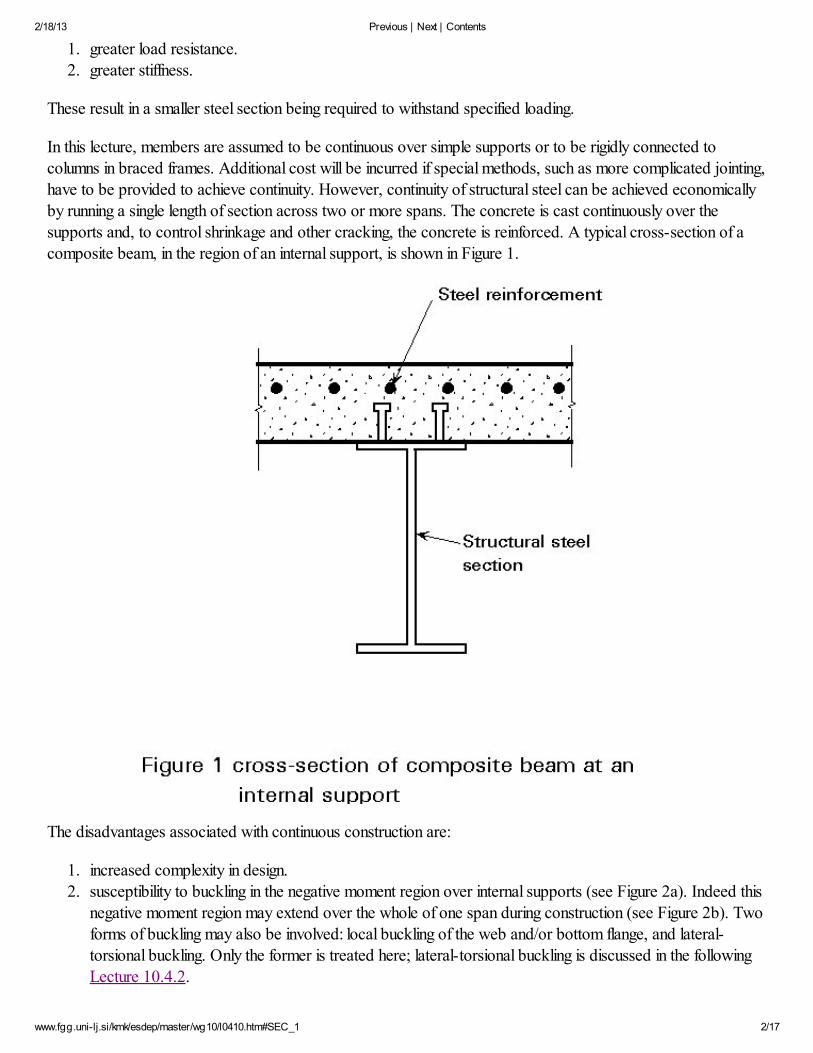
supports and, to control shrinkage and other cracking, the concrete is reinforced. A typical cross-section of a
composite beam, in the region of an internal support, is shown in Figure 1.
The disadvantages associated with continuous construction are:
1. increased complexity in design.
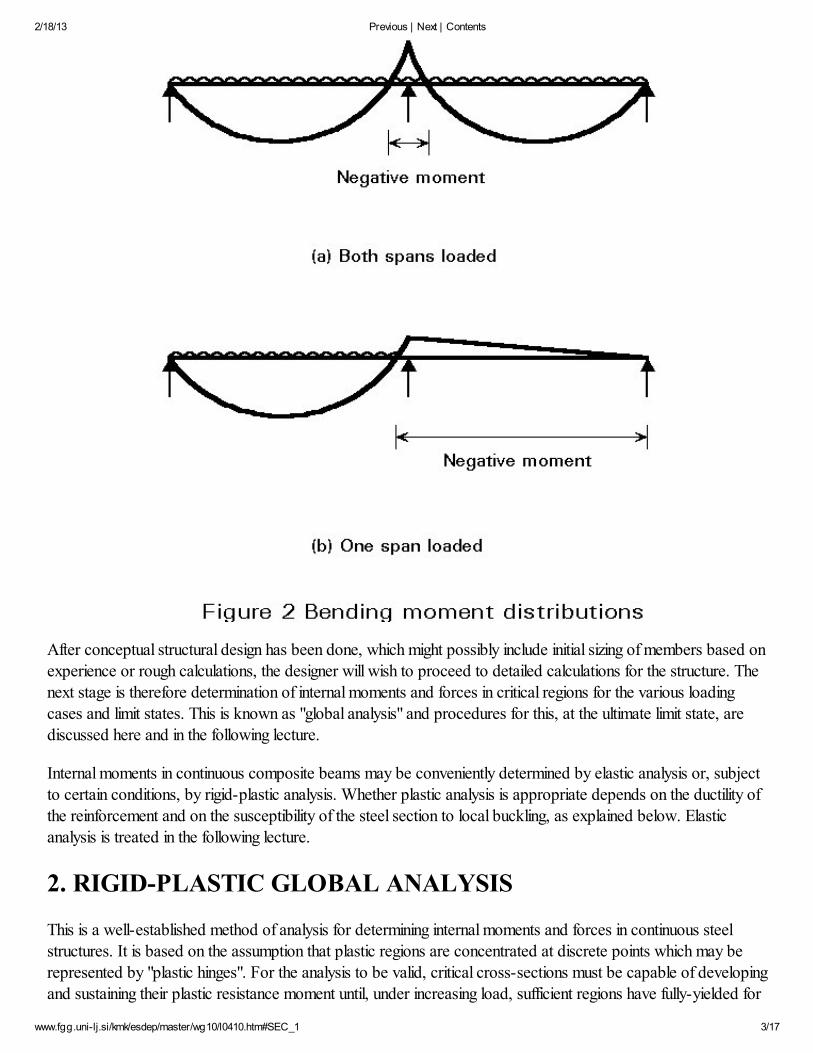
2. susceptibility to buckling in the negative moment region over internal supports (see Figure 2a). Indeed thisnegative moment region may extend over the whole of one span during construction (see Figure 2b). Two
forms of buckling may also be involved: local buckling of the web and/or bottom flange, and lateral-torsional buckling. Only the former is treated here; lateral-torsional buckling is discussed in the following
Lecture 10.4.2.
2/18/13 Previous | Next | Contents
www.fgg.uni-lj.si/kmk/esdep/master/wg10/l0410.htm#SEC_1 3/17
After conceptual structural design has been done, which might possibly include initial sizing of members based onexperience or rough calculations, the designer will wish to proceed to detailed calculations for the structure. The
next stage is therefore determination of internal moments and forces in critical regions for the various loadingcases and limit states. This is known as "global analysis" and procedures for this, at the ultimate limit state, are
discussed here and in the following lecture.
Internal moments in continuous composite beams may be conveniently determined by elastic analysis or, subjectto certain conditions, by rigid-plastic analysis. Whether plastic analysis is appropriate depends on the ductility ofthe reinforcement and on the susceptibility of the steel section to local buckling, as explained below. Elastic
analysis is treated in the following lecture.
2. RIGID-PLASTIC GLOBAL ANALYSIS
This is a well-established method of analysis for determining internal moments and forces in continuous steel
structures. It is based on the assumption that plastic regions are concentrated at discrete points which may be
represented by "plastic hinges". For the analysis to be valid, critical cross-sections must be capable of developing
and sustaining their plastic resistance moment until, under increasing load, sufficient regions have fully-yielded for
2/18/13 Previous | Next | Contents
www.fgg.uni-lj.si/kmk/esdep/master/wg10/l0410.htm#SEC_1 4/17
the plastic hinges to form a mechanism.
The mechanism arises as a result of redistribution of moment which is achieved by rotation of the already-yieldedregions. To ensure that the resulting strains can be accommodated without a reduction in resistance below the
plastic moment, limitations must be placed on the slenderness of the elements of the cross-sections which are in
compression. For steel structures, sections which can form a plastic hinge with the rotation capacity required for
plastic global analysis, are designated Class 1 cross-sections. The limitations on flange slenderness and webslenderness for such sections are given in design recommendations, such as Eurocode 3 [1], as discussed in
Lectures 7.2 and 7.3. These limitations recognise that some loss of rotation capacity due to local buckling will be
offset by beneficial effects such as strain-hardening and the finite length of plastic regions. However, because of
the latter effect, it is necessary that cross-sections away from the theoretical locations are also in Class 1, or atleast in Class 2. By definition, Class 2 cross-sections can develop the plastic resistance moment of the section
although local buckling limits the rotation capacity and prevents full redistribution of moment at such sections.
3. BEHAVIOUR OF CONTINUOUS COMPOSITE BEAMS
The flexural performance of continuous composite beams has been investigated by tests in which the secondary
elements (shear connectors, transverse slab reinforcement) were conservatively designed in order to preclude
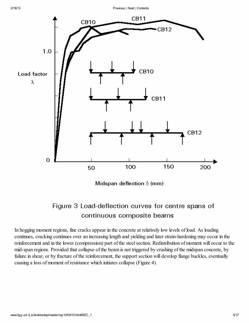
forms of failure such as loss of interaction and longitudinal splitting of the slab. Initially, the behaviour issubstantially linear (Figure 3), but as load increases reduction in flexural stiffness occurs.
2/18/13 Previous | Next | Contents
www.fgg.uni-lj.si/kmk/esdep/master/wg10/l0410.htm#SEC_1 5/17
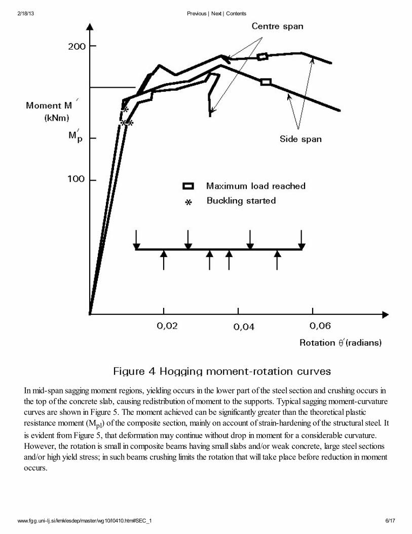
In hogging moment regions, fine cracks appear in the concrete at relatively low levels of load. As loading
continues, cracking continues over an increasing length and yielding and later strain-hardening may occur in the
reinforcement and in the lower (compression) part of the steel section. Redistribution of moment will occur to themid-span regions. Provided that collapse of the beam is not triggered by crushing of the midspan concrete, by
failure in shear, or by fracture of the reinforcement, the support section will develop flange buckles, eventually
causing a loss of moment of resistance which initiates collapse (Figure 4).
2/18/13 Previous | Next | Contents
www.fgg.uni-lj.si/kmk/esdep/master/wg10/l0410.htm#SEC_1 6/17
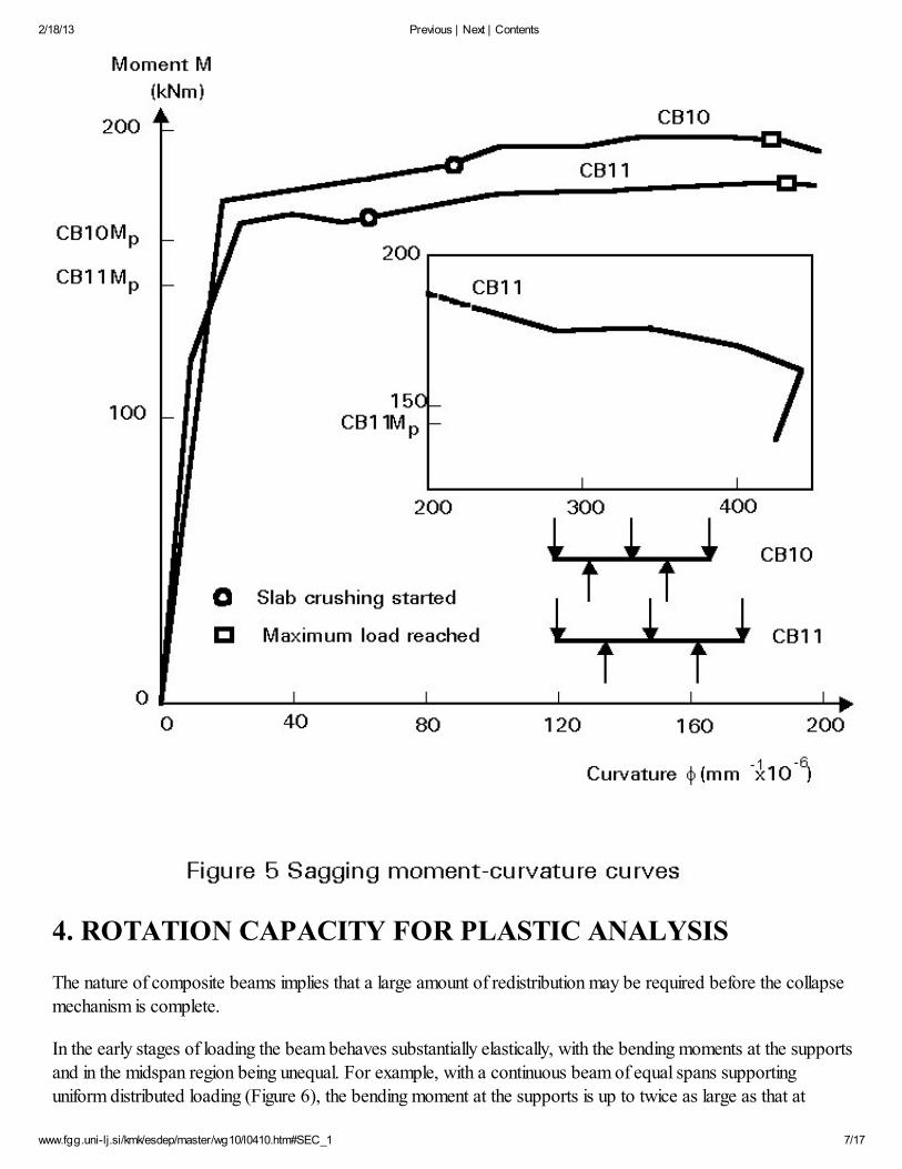
In mid-span sagging moment regions, yielding occurs in the lower part of the steel section and crushing occurs in
the top of the concrete slab, causing redistribution of moment to the supports. Typical sagging moment-curvature
curves are shown in Figure 5. The moment achieved can be significantly greater than the theoretical plastic
resistance moment (Mpl) of the composite section, mainly on account of strain-hardening of the structural steel. It
is evident from Figure 5, that deformation may continue without drop in moment for a considerable curvature.
However, the rotation is small in composite beams having small slabs and/or weak concrete, large steel sections
and/or high yield stress; in such beams crushing limits the rotation that will take place before reduction in moment
occurs.
2/18/13 Previous | Next | Contents
www.fgg.uni-lj.si/kmk/esdep/master/wg10/l0410.htm#SEC_1 7/17
4. ROTATION CAPACITY FOR PLASTIC ANALYSIS
The nature of composite beams implies that a large amount of redistribution may be required before the collapse
mechanism is complete.
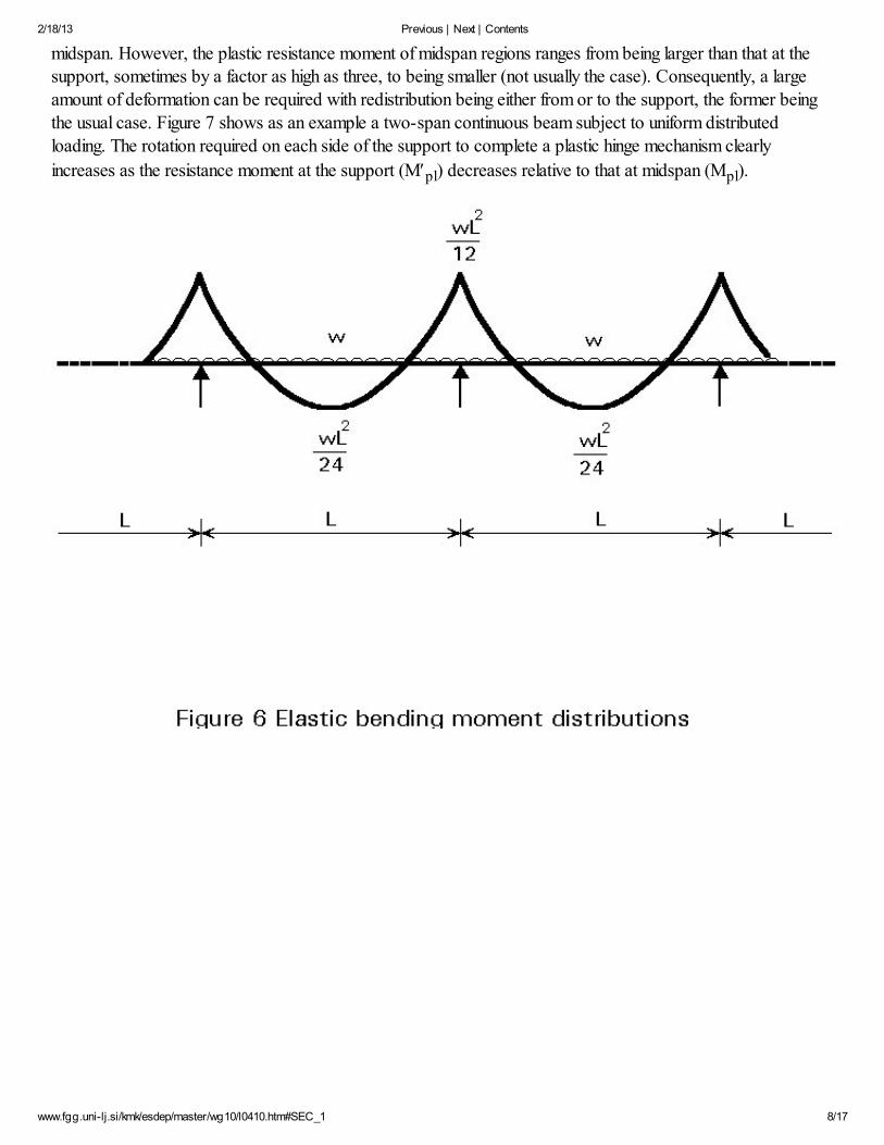
In the early stages of loading the beam behaves substantially elastically, with the bending moments at the supports
and in the midspan region being unequal. For example, with a continuous beam of equal spans supporting
uniform distributed loading (Figure 6), the bending moment at the supports is up to twice as large as that at
2/18/13 Previous | Next | Contents
www.fgg.uni-lj.si/kmk/esdep/master/wg10/l0410.htm#SEC_1 8/17
midspan. However, the plastic resistance moment of midspan regions ranges from being larger than that at thesupport, sometimes by a factor as high as three, to being smaller (not usually the case). Consequently, a large
amount of deformation can be required with redistribution being either from or to the support, the former being
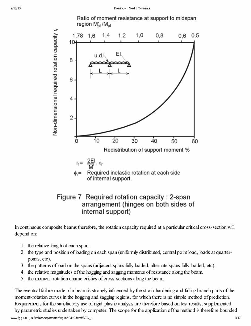
the usual case. Figure 7 shows as an example a two-span continuous beam subject to uniform distributed
loading. The rotation required on each side of the support to complete a plastic hinge mechanism clearly
increases as the resistance moment at the support (M¢pl) decreases relative to that at midspan (Mpl).
2/18/13 Previous | Next | Contents
www.fgg.uni-lj.si/kmk/esdep/master/wg10/l0410.htm#SEC_1 9/17
In continuous composite beams therefore, the rotation capacity required at a particular critical cross-section will
depend on:
1. the relative length of each span.
2. the type and position of loading on each span (uniformly distributed, central point load, loads at quarter-
points, etc).
3. the patterns of load on the spans (adjacent spans fully loaded, alternate spans fully loaded, etc).
4. the relative magnitudes of the hogging and sagging moments of resistance along the beam.
5. the moment-rotation characteristics of cross-sections along the beam.
The eventual failure mode of a beam is strongly influenced by the strain-hardening and falling branch parts of themoment-rotation curves in the hogging and sagging regions, for which there is no simple method of prediction.
Requirements for the satisfactory use of rigid-plastic analysis are therefore based on test results, supplemented
by parametric studies undertaken by computer. The scope for the application of the method is therefore bounded
2/18/13 Previous | Next | Contents
www.fgg.uni-lj.si/kmk/esdep/master/wg10/l0410.htm#SEC_1 10/17
by that of the parametric studies.
5. RIGID-PLASTIC ANALYSIS IN EUROCODE 4
The requirements proposed in Eurocode 4 [2], Section 4.5.2.2, to achieve sufficient rotation capacity, permit thescope for rigid-plastic analysis to be given without reference to the strain-hardening properties of steel, which are
not usually known by the designer. The requirements are:
1. At each plastic hinge location, the cross-section of the structural steel component shall be symmetrical
about the plane of its web.
2. All effective cross-sections at plastic hinge locations are in Class 1; all other effective cross-sections are in
Class 1 or Class 2.
3. Adjacent spans do not differ in length by more than 50% of the shorter span.4. End spans do not exceed 115% of the length of the adjacent span.
5. In any span in which more than half the total design load is concentrated within a length of one-fifth of the
span, then at any hinge location where the concrete slab is in compression, not more than 15% of the
overall depth of the member should be in compression (this condition does not apply if the hinge will be
the last to form in that span).
6. The steel compression flange at a plastic hinge location is laterally restrained (this is usually so, as
explained later).
6. CLASSIFICATION OF CROSS-SECTIONS
It can be seen from the above requirements that, unlike steel structures, the definition of a Class 1 section in
terms of limiting breadth/thickness ratios is not in itself sufficient to ensure always that enough rotation capacitywill be available for plastic analysis in composite construction. Provided, however, that the requirements given
above concerning relative lengths of spans and arrangement of loading are satisfied, the limits on
breadth/thickness ratios for a Class 1 composite section can be taken as those for steel sections given in
Eurocode 3 [1]. The limits for Class 1 and Class 2 sections, given in Tables 1(a) and (b) of this lecture, have
been taken from Tables 4.1 and 4.2, respectively, of Eurocode 4 [2].
For Class 2 sections, web encasement may be assumed to contribute to resistance to local buckling, provided
that it is reinforced and mechanically connected to the steel section.
7. PLASTIC RESISTANCE MOMENTS
The plastic resistance of a composite beam in sagging bending has been described in Lecture 10.2. The upper
flange of the steel section may be in compression but is restrained laterally through its connection to the concrete
slab.
The negative moment of resistance can be determined as described below. The lower flange of the steel section
is now in compression. However, this flange is usually restrained laterally by connection to a supporting element,
such as a column, which is itself prevented, at beam level, from moving out-of-plane.
It is assumed that the effect of co-existent vertical shear on the bending resistance can be neglected. When the
2/18/13 Previous | Next | Contents
www.fgg.uni-lj.si/kmk/esdep/master/wg10/l0410.htm#SEC_1 11/17
shear force exceeds half the plastic shear resistance of the web of the steel section, allowance should be made
for its effect on the resistance moment, as described in the previous lecture.
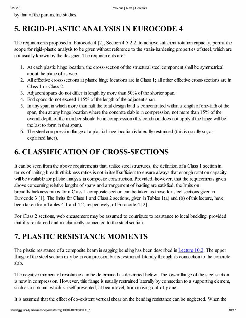
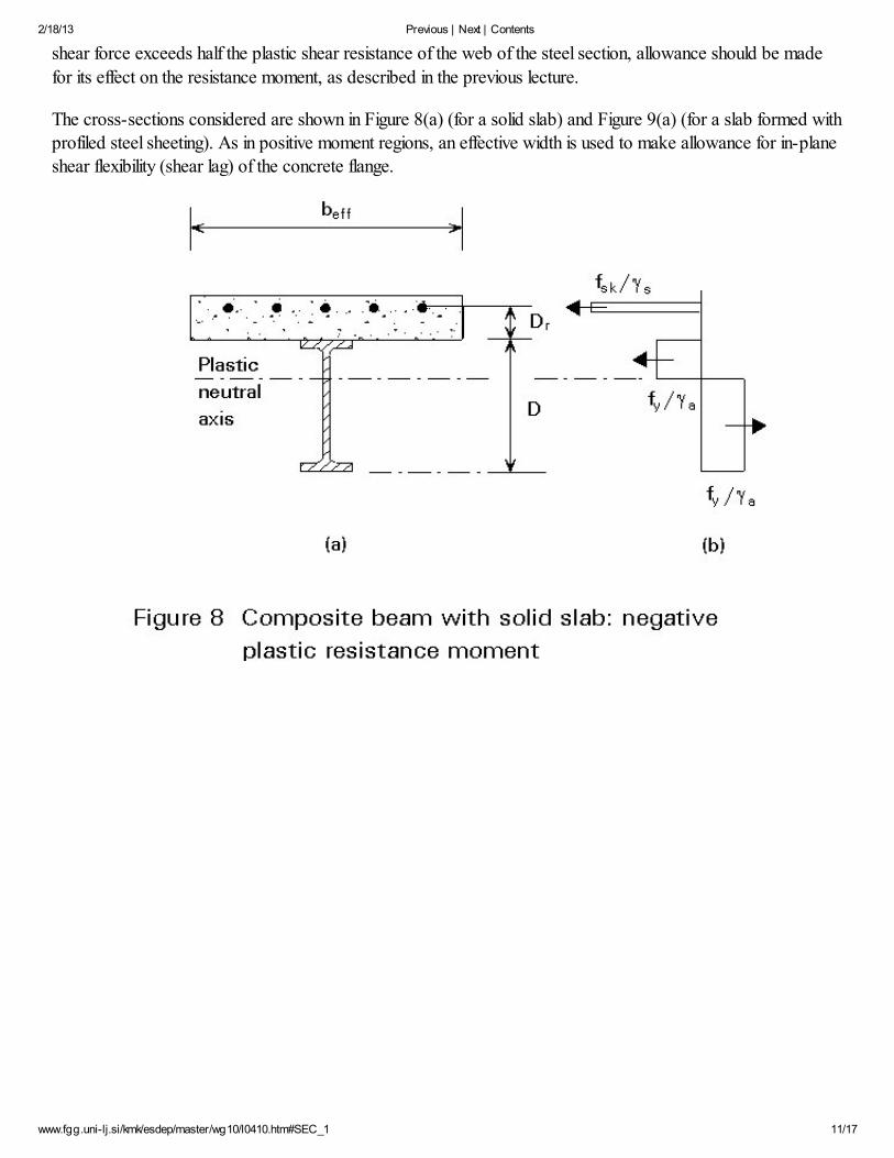
The cross-sections considered are shown in Figure 8(a) (for a solid slab) and Figure 9(a) (for a slab formed with
profiled steel sheeting). As in positive moment regions, an effective width is used to make allowance for in-plane
shear flexibility (shear lag) of the concrete flange.
2/18/13 Previous | Next | Contents
www.fgg.uni-lj.si/kmk/esdep/master/wg10/l0410.htm#SEC_1 12/17
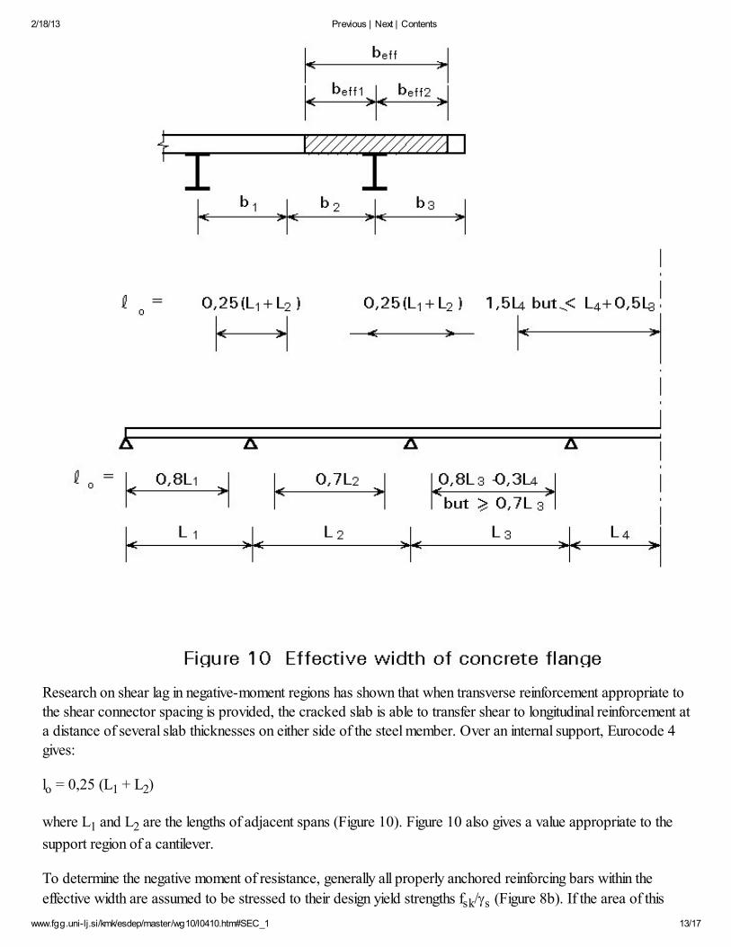
The ratio of the effective width to the real flange width depends on many factors, including the type of loading,the support conditions, the cross-section considered and the ratio of beam spacing to span. In most designrecommendations (particularly for buildings), however, very simple formulae are given for effective width, related
to the span(s) of the beam and expressed in terms of a length lo between points of contraflexure; these should be
taken simply as follows:
End span lo = 0,8L
Internal span lo = 0,7L
where L is the distance between supports for the span concerned, i.e. L1 or L2 in Figure 10, which has been
taken from Figure 4.3 of Eurocode 4 [2]; this also gives a value appropriate for a span next to a cantilever, i.e.
L3.
2/18/13 Previous | Next | Contents
www.fgg.uni-lj.si/kmk/esdep/master/wg10/l0410.htm#SEC_1 13/17
Research on shear lag in negative-moment regions has shown that when transverse reinforcement appropriate tothe shear connector spacing is provided, the cracked slab is able to transfer shear to longitudinal reinforcement at
a distance of several slab thicknesses on either side of the steel member. Over an internal support, Eurocode 4gives:
lo = 0,25 (L1 + L2)
where L1 and L2 are the lengths of adjacent spans (Figure 10). Figure 10 also gives a value appropriate to the
support region of a cantilever.
To determine the negative moment of resistance, generally all properly anchored reinforcing bars within the
effective width are assumed to be stressed to their design yield strengths fsk/gs (Figure 8b). If the area of this
2/18/13 Previous | Next | Contents
www.fgg.uni-lj.si/kmk/esdep/master/wg10/l0410.htm#SEC_1 14/17
reinforcement is Ar, then the tensile resistance of the reinforcement, Rr, within the effective width of the slab
under negative moment is given by:
Rr = (fsk/gs)Ar
Due to the possibility of fracture caused by lack of ductility, nominal slab reinforcement (i.e. welded mesh or bars
of less than 10mm diameter) should be neglected in calculating Rr. All bars included when calculating Rr should
be of high ductility (Class H) as defined in Eurocode 2 [3].
At flexural failure, the whole of the concrete slab may be assumed to be cracked, whilst all the structural steel is
at its design yield strength fy/ga in tension or compression. The plastic neutral axis may be in the top flange or in
the web. For the latter case, the stresses are shown in Figure 8(b). The position of the neutral axis is determined
by considering longitudinal equilibrium.
Let Rw be the axial resistance of the web over a depth d between the flanges. Then for a steel section with equal
flanges, the plastic neutral axis will lie in the web if Rr<Rw, whilst if Rr>Rw, the neutral axis will lie in the steel
flange. For each case an expression for the negative plastic resistance moment M¢pl, can be determined by
considering the moment of each rectangular stress block about the neutral axis.
Case 1: Rr < Rw (plastic neutral axis lies in web)
M¢pl = Ma + Rr
where Ma is the plastic resistance moment of the steel section alone;
D is the overall depth of the steel section;
Dr is the distance from the top of the steel beam to the centroid of the reinforcement.
Case 2: Rr > Rw (plastic neutral axis lies in steel flange)
Assuming the thickness of the flange is small:
M¢pl = Rs + RrDr
where Rs is the tensile resistance of the steel section. For a section of cross-sectional area Aa,
Rs = (fy/ga)Aa.
The cross-section shown in Figure 9 shows a slab formed with profiled steel sheeting. The sheeting component isusually neglected when determining the negative moment of resistance. For construction with profiled steelsheeting, it is common practice to provide only a light mesh reinforcement in the slab, which, as mentioned
above, is neglected when calculating Rr. Thus if no further reinforcement is provided (additional to the sheeting
2/18/13 Previous | Next | Contents
www.fgg.uni-lj.si/kmk/esdep/master/wg10/l0410.htm#SEC_1 15/17
and the mesh), the negative plastic resistance moment is given by M¢pl=Ma.
8. DISTRIBUTION OF BENDING MOMENT
To design a suitable cross-section against flexure, it remains to determine the distribution of bending momentsdue to the applied load.
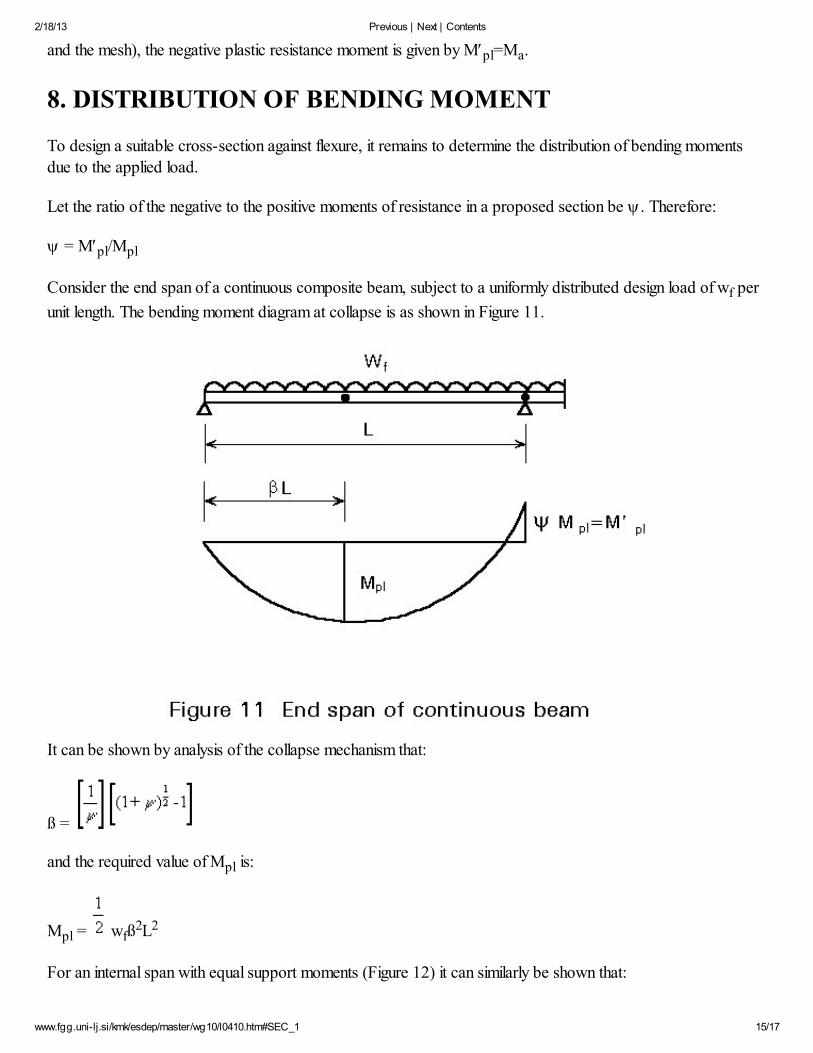
Let the ratio of the negative to the positive moments of resistance in a proposed section be y. Therefore:
y = M¢pl/Mpl
Consider the end span of a continuous composite beam, subject to a uniformly distributed design load of wf per
unit length. The bending moment diagram at collapse is as shown in Figure 11.
It can be shown by analysis of the collapse mechanism that:
ß =
and the required value of Mpl is:
Mpl = wfß2L2
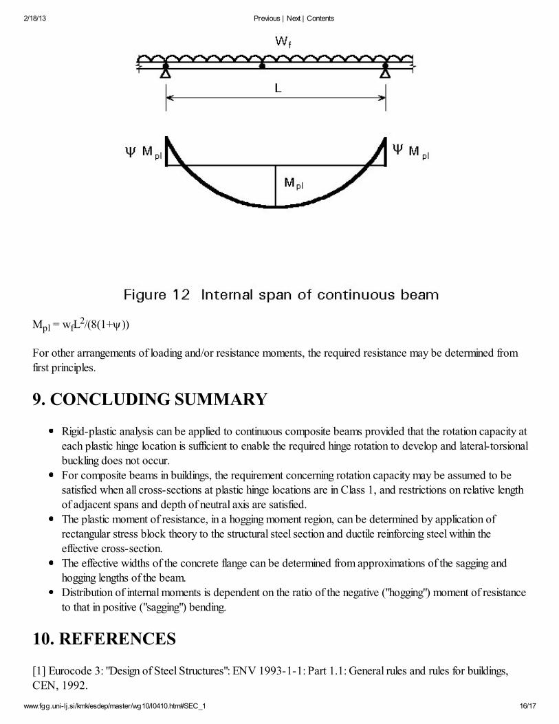
For an internal span with equal support moments (Figure 12) it can similarly be shown that:
2/18/13 Previous | Next | Contents
www.fgg.uni-lj.si/kmk/esdep/master/wg10/l0410.htm#SEC_1 16/17
Mpl = wfL2/(8(1+y))
For other arrangements of loading and/or resistance moments, the required resistance may be determined from
first principles.
9. CONCLUDING SUMMARY
Rigid-plastic analysis can be applied to continuous composite beams provided that the rotation capacity at
each plastic hinge location is sufficient to enable the required hinge rotation to develop and lateral-torsionalbuckling does not occur.For composite beams in buildings, the requirement concerning rotation capacity may be assumed to be
satisfied when all cross-sections at plastic hinge locations are in Class 1, and restrictions on relative lengthof adjacent spans and depth of neutral axis are satisfied.
The plastic moment of resistance, in a hogging moment region, can be determined by application ofrectangular stress block theory to the structural steel section and ductile reinforcing steel within the
effective cross-section.The effective widths of the concrete flange can be determined from approximations of the sagging and
hogging lengths of the beam.Distribution of internal moments is dependent on the ratio of the negative ("hogging") moment of resistanceto that in positive ("sagging") bending.
10. REFERENCES
[1] Eurocode 3: "Design of Steel Structures": ENV 1993-1-1: Part 1.1: General rules and rules for buildings,CEN, 1992.
2/18/13 Previous | Next | Contents
www.fgg.uni-lj.si/kmk/esdep/master/wg10/l0410.htm#SEC_1 17/17
[2] Eurocode 4: "Design of Composite Steel and Concrete Structures": ENV1994-1-1: Part 1.1: General rulesand rules for buildings, CEN (in press).
[3] Eurocode 2: "Design of Concrete Structures": ENV 1992-1-1: Part 1.1: General rules and rules for buildings,
CEN, 1992.
11. ADDITIONAL READING
1. Johnson R.P., "Composite Structures of Steel and Concrete: Volume 1: Beams, Columns, Frames and
Applications in Building", Granada, 1975.2. Johnson R.P. and Buckby R.J., "Composite Structures of Steel and Concrete: Volume 2: Bridges",
Second edition, Collins, 1986.3. Brett P.R., Nethercot D.A. and Owens G.W., "Continuous Construction in Steel for Roofs and
Composite Floors", Structural Engineer, Volume 65A, October 1987, pp. 355-368.4. Johnson R.P. and Hope-Gill M.C., "Tests on Three Three-Span Continuous Composite Beams",
Proc.Inst.Civ.Engrs., Part2, Vol.61, June 1976, pp. 367-381.5. Johnson R.P. and Hope-Gill M.C., "Applicability of Simple Plastic Theory to Continuous Composite
Beams", Proc.Inst.Civ.Engrs., Part 2, Vol.61, March 1976, pp. 127-143.
6. Ansourian P., "Experiments on Continuous Composite Beams", Proc.Inst.Civ.Engrs., Part 2, Vol.71,December 1981, pp. 25-51.
The references given in Lecture 10.1 are also relevant.
Previous | Next | Contents