10151 - static.maerklin.de · ting remains set to “pulling in” (10152 ––> 10151). (point...
TRANSCRIPT
Kehrschleifen-Garnitur
10151

2
Die LGB-Kehrschleifen-Garnitur 10151 enthält ein normales Trenngleis T und ein Spezialgleis K (Diodengleis), das mit einem Fahrtrichtungspfeil gekenn-zeichnet ist. Damit ist das Befahren von Kehrschleifen ohne besondere Verkabelungen und Schalter problem-los möglich. Kehrschleifenfahrt mit oder ohne Halt:Ein Zug fährt mit der Reglereinstellung (1) in die Kehrschleife und wird am Bahnhof angehalten. Reg-lerstellung (0). Dann wird der Reglerknopf in Stellung (2) gedreht, der Zug verlässt die Kehrschleife. Die Wei-chenstellung bleibt immer auf Einfahrt (10152 ––> 10151) stehen (Handweiche) (Bild 1). Bei Durchfahrt ohne Halt wird der Traforeglerknopf schnell von der Stellung 1 über 0 nach 2 gedreht, wäh-rend der Zug im Kehrschleifenbogen fährt.Für technisch neugierige LGB-Bahner ein Blick in das Innere eines Diodengleises Hier sind 4 Dioden eingebaut (Bild 2). Diese Bauele-mente aus der Elektronik haben die Eigenschaft der Polaritätsabhängigkeit: Sie lassen Strom nur in einer be-stimmten Fahrtrichtung durch, die andere wird gesperrt. Wie man an den Funktionsschaltbildern erkennt (Bild 3), bleibt trotz Umpolung am Trafo die Polarität in der Kehrschleifenstrecke die gleiche. Diesen technischen Vorgang kann man vergessen, wenn man die nun
folgenden Einbauvorschläge beachtet. Regeln für Kehrschleifen im Gleisplan • Die Kehrschleifen-Durchfahrt ist nur in einer (festzu-
legenden) Richtung möglich. • Das Trenngleis T wird in Fahrtrichtung nach der
Einfahrweiche (Handweiche) eingebaut. • Das Kehrschleifengleis K wird kurz vor der Ausfahrt
aus der Kehrschleife eingebaut, mit Pfeil zur Weiche zeigend.
• Der gegenseitige Abstand von T- und K-Gleis sollte mindestens die Länge des Zuges haben. Damit besteht genügend Zeit zur Umpolung. Bei Einsatz des beleuchteten Post-Gepäckwagens 30190 muss dieser Abstand mindestens die volle Zuglänge haben.
• Rangieren in diesem Gleisabschnitt ist nicht möglich!• Während der Fahrt durch die Kehrschleife muss der
Fahrreglerknopf über die Nullstellung zur anderen Seite gedreht werden, damit der Zug die Kehrschleife wieder verlassen kann (er fährt ja dann auf dem Streckengleis in entgegengesetzter Richtung!).
3
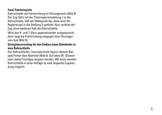
Zwei Fahrbeispiele Kehrschleife mit Fahrtrichtung im Uhrzeigersinn (Bild 4). Der Zug fährt mit der Traforeglereinstellung 1 in die Kehrschleife, hält am Haltepunkt Hp; dann wird der Reglerknopf in die Stellung 2 gedreht. Nun verlässt der Zug ohne weiteren Halt die Kehrschleife. Wird das K- und T-Gleis gegeneinander ausgetauscht, dann liegt die Fahrtrichtung entgegen dem Uhrzeiger-sinn fest (Bild 5).Gleisplanvorschlag für den Einbau eines Bahnhofes in eine Kehrschleife Der Kehrschleifen-Trennabschnitt liegt in diesem Bei-spiel hinter dem Bahnhof (Bild 6). Auf allen Bf.-Gleisen kann daher freizügig rangiert werden. Mit einer zweiten Kehrschleife in einer Anlage ist eine doppelte Zugwen-dung möglich.
4
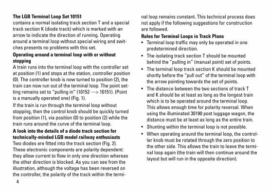
The LGB Terminal Loop Set 10151contains a normal isolating track section T and a special track section K (diode track) which is marked with an arrow to indicate the direction of running. Operating around a terminal loop without special wiring and swit-ches presents no problems with this set. Operating around a terminal loop with or without stopping A train runs into the terminal loop with the controller set at position (1) and stops at the station, controller position (0). The controller knob is now turned to position (2), the train can now run out of the terminal loop. The point set-ting remains set to “pulling in” (10152 ––> 10151). (Point is a manually operated one) (Fig. 1). If the train is run through the terminal loop without stopping, then the control knob should be quickly turned from position (1), via position (0) to position (2) while the train runs around the curve of the terminal loop. A look into the details of a diode track section for technically-minded LGB model railway enthusiastsTwo diodes are fitted into the track section (Fig. 2). These electronic components are polarity dependent: they allow current to flow in only one direction whereas the other direction is blocked. As you can see from the illustration, although the voltage has been reversed on the controller, the polarity of the track within the termi-
nal loop remains constant. This technical process does not apply if the following suggestions for construction are followed. Rules for Terminal Loops in Track Plans • Terminal loop traffic may only be operated in one
predetermined direction. • The isolating track section T should be mounted
behind the “pulling in” (manual point) set of points.• The terminal loop track section K should be mounted
shortly before the “pull out” of the terminal loop with the arrow pointing towards the set of points.
• The distance between the two sections of track T and K should be at least as long as the longest train which is to be operated around the terminal loop. This allows enough time for polarity reversal. When using the illuminated 30190 post luggage wagon, the distance must be at least as long as the entire train.
• Shunting within the terminal loop is not possible. • When operating around the terminal loop, the control-
ler knob must be rotated through the zero position to the other side. This allows the train to leave the termi-nal loop again (the train will then continue around the layout but will run in the opposite direction).
5
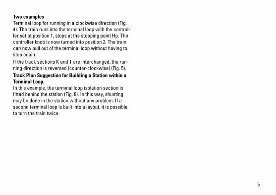
Two examplesTerminal loop for running in a clockwise direction (Fig. 4). The train runs into the terminal loop with the control-ler set at position 1, stops at the stopping point Hp. The controller knob is now turned into position 2. The train can now pull out of the terminal loop without having to stop again. If the track sections K and T are interchanged, the run-ning direction is reversed (counter-clockwise) (Fig. 5). Track Plan Suggestion for Building a Station within a Terminal Loop. In this example, the terminal loop isolation section is fitted behind the station (Fig. 6). In this way, shunting may be done in the station without any problem. If a second terminal loop is built into a layout, it is possible to turn the train twice.
6
Le jeu de boucles de retour LGB10151 comprend une voie normale de séparation T et une voie spéciale K (voie à diodes) qui sont marquées d’une flèche indiquant le sens de marche. Ainsi, il est possible de circuler sans problèmes sur des boucles de retour, sans câblages spéciaux, ni interrupteur. Circulation sur boucle de retour avec ou sans arrêt Un train circule sur la boucle de retour, régulateur en position (1), et s’arrête en gare. Régulateur en position (0). Le train quitte la boucle de retour après avoir amené le bouton du règulateur en position (2). La position de l’aiguillage reste toujours sur entrée (10152 ––> 10151) (aiguillage manuel) (Img. 1). Pour un passage sans arrêt, il faut amener rapidement le bouton du transformateur de la position 1 à la position 2, en passant par 0 pendant que le train circule sur la courbe de la boucle de retour. Un aperçu de la construction de la voie à diode pour les cheminots intéressés par la technique Quatre diodes sont incorporées (Img. 2). Ces compo-sants électroniques sont dépendants de la polarité: ils ne laissent passer le courant que dans un sens détermi-né, l’autre est alors bloqué. Le schéma des connexions montre que la polarité dans la boucle de retour reste la même, et cela malgré une inversion des pôles au trans-formateur (Img. 3). Cette opération n’est pas nécessaire
si l’on observe les propositions suivantes d’installation. Règles à observer pour boucles de retour dans le plan de voies • Le passage des boucles de retour n’est possible que
dans un sens (à définir). • La voie de séparation T est montée dans le sens de
la marche, après l’aiguillage d’entrée (aiguillage manuel).
• La voie de boucle de retour K est montée juste avant de quitter la boucle de retour, avec une flèche indi-quant l’aiguille.
• L’écartement des voies T et K devrait correspondre au moins à la longueur du train afin d’avoir assez de temps pour l’inversion des pôles. Il faut que cet écartement ait au moins la longueur totale du train pour utilisation du fourgon postal 30190 éclairé.
• Une manoeuvre est impossible sur cette section de voie!
• Pendant la circulation par la boucle de retour, il faut amener le bouton de réglage par la position zéro sur l’autre côté afin que le train puisse quitter à nouveau la boucle de retour (il circule alors sur la voie dans le sens contraire!).
7
Deux exemples de marche Boucle de retour avec sens de marche dans les aiguilles d’une montre (Img. 4). Le train entre dans la boucle de retour lorsque le transformateur est en position 1, s’arrête au point Hp. Il faut alors amener le bouton du transformateur en position 2 pour que le train quitte la boucle de retour sans s’arrêter. Si les voies K et T sont échangées, le sens de marche est alors contraire à celui des aiguilles d’une montre (Img. 5). Proposition d’un plan de voies pour l’aménagement d’une gare dans une boucle de retour Dans cet exemple, la section de séparation de la boucle de retour se trouve derrière la gare (Img. 6). On peut alors manoeuvrer librement sur toutes le voies de la gare. Le montage d’une deuxième boucle de retour sur le circuit permet un double changement de marche du train.

8
Bild 1 Kehrschleifenfahrt mit oder ohne HaltFig. 1 terminal loop with or without stoppingImg. 1 Circulation sur boucle de retour avec ou sans
arrêt

9
Bild 2 Fig. 2 Img. 2
Bild 3 Fig. 3 Img. 3

10
Bild 4 Fahrtrichtung im UhrzeigersinnFig. 4 running in a clockwise directionImg. 4 Direction aiguilles d‘une montre
Bild 5 Fahrtrichtung entgegen dem Uhrzeigersinn Fig. 5 running against clockwise directionImg. 5 Direction dans le sens contraire des aiguilles
d‘une montre

11
Bild 6 GleisplanvorschlagFig. 6 Track Plan SuggestionImg. 6 Proposition d’un plan de voies

129046/0211/Sm1EfÄnderungen vorbehalten
© Gebr. Märklin & Cie. GmbHwww.maerklin.com/en/imprint.html
Gebr. Märklin & Cie. GmbH Stuttgarter Straße 55 - 57 73033 Göppingen Deutschland www.lgb.de