10 bench drill press - best woodworking tools - mike's … bench drill press (model dp200) part...
TRANSCRIPT
INS
TRU
CTIO
NM
AN
UA
L10" Bench Drill Press
(Model DP200)
PART NO. 906770 - 07-01-02Copyright © 2002 Delta Machinery
ESPAÑOL: PÁGINA 17To learn more about DELTA MACHINERY visit our website at: www.deltamachinery.com.For Parts, Service, Warranty or other Assistance,
please call 1-800-223-7278 (In Canada call 1-800-463-3582).

2
GENERAL SAFETY RULESWoodworking can be dangerous if safe and proper operating procedures are not followed. As with all machinery, thereare certain hazards involved with the operation of the product. Using the machine with respect and caution willconsiderably lessen the possibility of personal injury. However, if normal safety precautions are overlooked or ignored,personal injury to the operator may result. Safety equipment such as guards, push sticks, hold-downs, featherboards,goggles, dust masks and hearing protection can reduce your potential for injury. But even the best guard won’t makeup for poor judgment, carelessness or inattention. Always use common sense and exercise caution in the workshop.If a procedure feels dangerous, don’t try it. Figure out an alternative procedure that feels safer. REMEMBER: Yourpersonal safety is your responsibility.
This machine was designed for certain applications only. Delta Machinery strongly recommends that this machine notbe modified and/or used for any application other than that for which it was designed. If you have any questions relativeto a particular application, DO NOT use the machine until you have first contacted Delta to determine if it can or shouldbe performed on the product.
Technical Service ManagerDelta Machinery4825 Highway 45 NorthJackson, TN 38305
(IN CANADA: 505 SOUTHGATE DRIVE, GUELPH, ONTARIO N1H 6M7)
WARNING: FAILURE TO FOLLOW THESE RULES MAY RESULT IN SERIOUS PERSONAL INJURY
1. FOR YOUR OWN SAFETY, READ INSTRUCTIONMANUAL BEFORE OPERATING THE TOOL. Learn thetool’s application and limitations as well as the specifichazards peculiar to it.
2. KEEP GUARDS IN PLACE and in working order.3. ALWAYS WEAR EYE PROTECTION. Wear safety
glasses. Everyday eyeglasses only have impact resistantlenses; they are not safety glasses. Also use face or dustmask if cutting operation is dusty. These safety glassesmust conform to ANSI Z87.1 requirements. NOTE:Approved glasses have Z87 printed or stamped on them.
4. REMOVE ADJUSTING KEYS AND WRENCHES. Formhabit of checking to see that keys and adjusting wrenchesare removed from tool before turning it “on”.
5. KEEP WORK AREA CLEAN. Cluttered areas andbenches invite accidents.
6. DON’T USE IN DANGEROUS ENVIRONMENT. Don’tuse power tools in damp or wet locations, or expose themto rain. Keep work area well-lighted.
7. KEEP CHILDREN AND VISITORS AWAY. All childrenand visitors should be kept a safe distance from work area.
8. MAKE WORKSHOP CHILDPROOF – with padlocks,master switches, or by removing starter keys.
9. DON’T FORCE TOOL. It will do the job better and besafer at the rate for which it was designed.10. USE RIGHT TOOL. Don’t force tool or attachment todo a job for which it was not designed.11. WEAR PROPER APPAREL. No loose clothing, gloves,neckties, rings, bracelets, or other jewelry to get caught inmoving parts. Nonslip footwear is recommended. Wearprotective hair covering to contain long hair.12. SECURE WORK. Use clamps or a vise to hold workwhen practical. It’s safer than using your hand and freesboth hands to operate tool.13. DON’T OVERREACH . Keep proper footing andbalance at all times.14. MAINTAIN TOOLS IN TOP CONDITION. Keep toolssharp and clean for best and safest performance. Followinstructions for lubricating and changing accessories.15. DISCONNECT TOOLS before servicing and whenchanging accessories such as blades, bits, cutters, etc.16. USE RECOMMENDED ACCESSORIES. The use ofaccessories and attachments not recommended by Deltamay cause hazards or risk of injury to persons.17. REDUCE THE RISK OF UNINTENTIONAL STARTING.Make sure switch is in “OFF” position before plugging inpower cord. In the event of a power failure, move switchto the “OFF” position.
18. NEVER STAND ON TOOL. Serious injury could occur ifthe tool is tipped or if the cutting tool is accidentallycontacted.19. CHECK DAMAGED PARTS. Before further use of thetool, a guard or other part that is damaged should becarefully checked to ensure that it will operate properly andperform its intended function – check for alignment ofmoving parts, binding of moving parts, breakage of parts,mounting, and any other conditions that may affect itsoperation. A guard or other part that is damaged should beproperly repaired or replaced.20. DIRECTION OF FEED. Feed work into a blade orcutter against the direction of rotation of the blade or cutteronly.21. NEVER LEAVE TOOL RUNNING UNATTENDED.TURN POWER OFF. Don’t leave tool until it comes to acomplete stop.22. STAY ALERT, WATCH WHAT YOU ARE DOING, ANDUSE COMMON SENSE WHEN OPERATING A POWERTOOL. DO NOT USE TOOL WHILE TIRED OR UNDERTHE INFLUENCE OF DRUGS, ALCOHOL, ORMEDICATION. A moment of inattention while operatingpower tools may result in serious personal injury.23. MAKE SURE TOOL IS DISCONNECTED FROMPOWER SUPPLY whi le motor is be ing mounted,connected or reconnected.24. THE DUST GENERATED by certain woods and woodproducts can be injurious to your health. Always operatemachinery in well ventilated areas and provide for properdust removal. Use wood dust collection systems wheneverpossible.25. WARNING: SOME DUST CREATED BYPOWER SANDING, SAWING, GRINDING, DRILLING,AND OTHER CONSTRUCTION ACTIVITIES containschemicals known to cause cancer, birth defects or otherreproductive harm. Some examples of these chemicalsare:· lead from lead-based paints,· crystalline silica from bricks and cement and other
masonry products, and· arsenic and chromium from chemically-treated lumber. Your risk from these exposures varies, depending on howoften you do this type of work. To reduce your exposureto these chemicals: work in a well ventilated area, andwork with approved safety equipment, such as thosedust masks that are specially designed to filter outmicroscopic particles.
SAVE THESE INSTRUCTIONS. Refer to them often and use them to instruct others.

3
ADDITIONAL SAFETY RULES FORFOR DRILL PRESSES
1. DO NOT OPERATE THIS TOOL UNTIL it isassembled and installed according to theinstructions.
2. OBTAIN ADVICE from your supervisor, instructor,or another qualified person if you are not familiarwith the operation of this tool.
3. FOLLOW ALL WIRING CODES and recommendedelectrical connections.
4. NEVER START THE MACHINE BEFORECLEARING THE TABLE of all objects (tools, scrappieces, etc.).
5. NEVER START THE MACHINE with the drill bit,cutting tool, or sander against the workpiece.
6. TIGHTEN ALL LOCK HANDLES before starting themachine.
7. USE ONLY DRILL BITS, CUTTING TOOLS,SANDING DRUMS, OR OTHER ACCESSORIESthat have shanks of 1/2" in diameter or less.
8. USE ONLY DRILL BITS, CUTTING TOOLS, ORSANDING DRUMS that are not damaged.
9. PROPERLY LOCK DRILL BIT, CUTTING TOOL,OR SANDING DRUM IN THE CHUCK beforeoperating this machine.
10. USE RECOMMENDED SPEEDS for all operations.11. AVOID AWKWARD OPERATIONS AND HAND
POSITIONS where a sudden slip could cause ahand to move into the cutting tool.
12. KEEP ARMS, HANDS, AND FINGERS away fromthe cutting tool.
13. HOLD THE WORKPIECE FIRMLY AGAINST THETABLE. Do not attempt to drill a workpiece thatdoes not have a flat surface against the table.Prevent the workpiece from rotating by clamping itto the table or by securing it against the drill presscolumn.
14. TURN THE MACHINE “OFF” AND WAIT FOR THEDRILL BIT, CUTTING TOOL, OR SANDER TOSTOP TURNING prior to cleaning the work area,removing debris, removing or securing workpiece,or changing the angle of the table. A moving drill bit,cutting tool, or sander can be dangerous.
15 PROPERLY SUPPORT LONG OR WIDEworkpieces.
16. NEVER PERFORM LAYOUT, ASSEMBLY, or set-up work on the table/work area when the machine isrunning.
17 TURN THE TOOL “OFF”, disconnect the tool fromthe power source before installing or removingaccessories, before adjusting or changing set-ups,or when making repairs.
18. DISCONNECT THE TOOL from the power source,and clean the table/work area before leaving thetool. LOCK THE SWITCH IN THE “OFF” POSITIONto prevent unauthorized use.
19. ADDITIONAL INFORMATION regarding the safeand proper operation of this tool is available from thePower Tool Institute, 1300 Summer Avenue,Cleveland, OH 44115-2851. Information is alsoavailable from the National Safety Council, 1121Spring Lake Drive, Itasca, IL 60143-3201. Pleasealso refer to the American National StandardsInstitute ANSI 01.1 Safety Requirements forWoodworking Machines and the U.S. Department ofLabor OSHA 1910.213 Regulations.
WARNING: FAILURE TO FOLLOW THESE RULES MAY RESULT IN SERIOUS PERSONAL INJURY.
SAVE THESE INSTRUCTIONS.Refer to them often
and use them to instruct others.

4
POWER CONNECTIONSA separate electrical circuit should be used for your machines. This circuit should not be less than #12 wire and shouldbe protected with a 20 Amp time lag fuse. If an extension cord is used, use only 3-wire extension cords which have 3-prong grounding type plugs and matching receptacle which will accept the machine’s plug. Before connecting themotor to the power line, make sure the switch is in the “OFF” position and be sure that the electric current is of thesame characteristics as indicated on the machine. All line connections should make good contact. Running on lowvoltage will damage the motor.
WARNING: DO NOT EXPOSE THE MACHINE TO RAIN OR OPERATE THE MACHINE IN DAMP LOCATIONS.
MOTOR SPECIFICATIONSYour machine is wired for 120 volt, 60 HZ alternating current. Before connecting the machine to the power source,make sure the switch is in the “OFF” position.
GROUNDING INSTRUCTIONSWARNING: THIS MACHINE MUST BE GROUNDED WHILE IN USE TO PROTECT THE OPERATOR FROMELECTRIC SHOCK.
Fig. A Fig. B
GROUNDED OUTLET BOX
CURRENTCARRYING
PRONGS
GROUNDING BLADEIS LONGEST OF THE 3 BLADES
GROUNDED OUTLET BOX
GROUNDINGMEANS
ADAPTER
2. Grounded, cord-connected machines intended for useon a supply circuit having a nominal rating less than 150volts:
If the machine is intended for use on a circuit that has anoutlet that looks like the one illustrated in Fig. A, themachine will have a grounding plug that looks like the plugillustrated in Fig. A. A temporary adapter, which looks likethe adapter illustrated in Fig. B, may be used to connectthis plug to a matching 2-conductor receptacle as shownin Fig. B if a properly grounded outlet is not available. Thetemporary adapter should be used only until a properlygrounded outlet can be installed by a qualified electrician.The green-colored rigid ear, lug, and the like, extendingfrom the adapter must be connected to a permanentground such as a properly grounded outlet box. Wheneverthe adapter is used, it must be held in place with a metalscrew.
NOTE: In Canada, the use of a temporary adapter is notpermitted by the Canadian Electric Code.
WARNING: IN ALL CASES, MAKE CERTAIN THE RECEPTACLE IN QUESTION IS PROPERLY
GROUNDED. IF YOU ARE NOT SURE HAVE AQUALIFIED ELECTRICIAN CHECK THE RECEPTACLE.
1. All grounded, cord-connected machines:
In the event of a malfunction or breakdown, groundingprovides a path of least resistance for electric current toreduce the risk of electric shock. This machine isequipped with an electric cord having an equipment-grounding conductor and a grounding plug. The plug mustbe plugged into a matching outlet that is properly installedand grounded in accordance with all local codes andordinances.
Do not modify the plug provided - if it will not fit the outlet,have the proper outlet installed by a qualified electrician.
Improper connection of the equipment-groundingconductor can result in risk of electric shock. Theconductor with insulation having an outer surface that isgreen with or without yellow stripes is the equipment-grounding conductor. If repair or replacement of theelectric cord or plug is necessary, do not connect theequipment-grounding conductor to a live terminal.
Check with a qualified electrician or service personnel ifthe grounding inst ruct ions are not complete lyunderstood, or if in doubt as to whether the machine isproperly grounded.
Use only 3-wire extension cords that have 3-pronggrounding type plugs and matching 3-conductorreceptacles that accept the machine’s plug, as shown inFig. A.
Repair or replace damaged or worn cord immediately.

Use proper extension cords. Make sure your extension cord is in good condition and is a 3-wire extension cord whichhas a 3-prong grounding type plug and matching receptacle which will accept the machine’s plug. When using anextension cord, be sure to use one heavy enough to carry the current of the machine. An undersized cord will causea drop in line voltage, resulting in loss of power and overheating. Fig. D, shows the correct gauge to use dependingon the cord length. If in doubt, use the next heavier gauge. The smaller the gauge number, the heavier the cord.
EXTENSION CORDS
OPERATING INSTRUCTIONSFOREWORD
Delta ShopMaster Model DP200 is a 10" bench drill press with a 1/4 H.P. motor, and a flexible work lamp. The DeltaShopMaster Model DP200 can handle most types of drill press operations.
UNPACKING AND CLEANINGCarefully unpack the machine and all loose items from the shipping container(s). Remove the protective coating fromall unpainted surfaces. This coating may be removed with a soft cloth moistened with kerosene (do not use acetone,gasoline or lacquer thinner for this purpose). After cleaning, cover the unpainted surfaces with a good quality householdfloor paste wax.
NOTICE: THE MANUAL COVER PHOTO ILLUSTRATES THE CURRENTPRODUCTION MODEL. ALL OTHER ILLUSTRATIONS ARE REPRESENTATIVE
ONLY AND MAY NOT DEPICT THE ACTUAL COLOR, LABELING ORACCESSORIES AND MAY BE INTENDED TO ILLUSTRATE TECHNIQUE ONLY.
5
Fig. D
MINIMUM GAUGE EXTENSION CORDRECOMMENDED SIZES FOR USE WITH STATIONARY ELECTRIC MACHINES
Ampere Total Length Gauge ofRating Volts of Cord in Feet Extension Cord
0-6 120 up to 25 18 AWG0-6 120 25-50 16 AWG0-6 120 50-100 16 AWG0-6 120 100-150 14 AWG
6-10 120 up to 25 18 AWG6-10 120 25-50 16 AWG6-10 120 50-100 14 AWG6-10 120 100-150 12 AWG
10-12 120 up to 25 16 AWG10-12 120 25-50 16 AWG10-12 120 50-100 14 AWG10-12 120 100-150 12 AWG
12-16 120 up to 25 14 AWG12-16 120 25-50 12 AWG12-16 120 GREATER THAN 50 FEET NOT RECOMMENDED
6
DRILL PRESS PARTS
Fig. 2
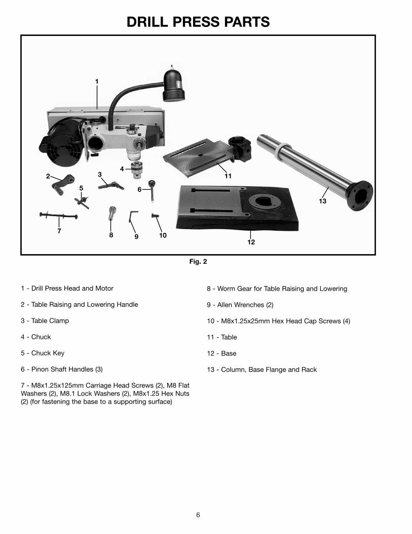
1 - Drill Press Head and Motor
2 - Table Raising and Lowering Handle
3 - Table Clamp
4 - Chuck
5 - Chuck Key
6 - Pinon Shaft Handles (3)
7 - M8x1.25x125mm Carriage Head Screws (2), M8 FlatWashers (2), M8.1 Lock Washers (2), M8x1.25 Hex Nuts(2) (for fastening the base to a supporting surface)
8 - Worm Gear for Table Raising and Lowering
9 - Allen Wrenches (2)
10 - M8x1.25x25mm Hex Head Cap Screws (4)
11 - Table
12 - Base
13 - Column, Base Flange and Rack
1
2 34
65
78 9 10
11
12
13

7
ASSEMBLYWARNING: FOR YOUR OWN SAFETY, DO NOT CONNECT THE MACHINE TO THE POWER SOURCE UNTIL THE
MACHINE IS COMPLETELY ASSEMBLED AND YOU READ AND UNDERSTAND THE ENTIRE INSTRUCTIONMANUAL.
1. Assemble the column (A) Fig. 3, to the base (B) usingthe four screws, three of which are shown at (C). Loosenset screw (D) and remove ring (E) and raising rack (F).
Fig. 3
Fig. 4
Fig. 5
G
H
H
G
Fig. 6
F
G
2. Make certain worm gear (G) Figs. 4 and 5, is in placein table bracket (H) as shown.
3. Insert raising rack (F) Fig. 6, which was removed inSTEP 1, into groove in table bracket making sure teethof worm gear (G) located inside table bracket areengaged with teeth of raising rack (F).
E D
F
A
BC C

8
Fig. 7
Fig. 8
Fig. 9
Fig. 10
G
K
L
F
F
J
D
E
F
4. Slide raising rack (F) Fig. 7, table and table bracketonto drill press column, as shown. Make sure bottom ofraising rack (F) Fig. 8, is inside the flange (J) on drill pressbase.
5. Re-assemble ring (E) Fig. 9, which was removed inSTEP 1. IMPORTANT: Bottom of ring (E) MUST NOT bepushed all the way down onto top of raising rack (F).MAKE SURE top of raising rack (F) is under bottom of ring(E) and that there is enough clearance to allow rack (F) torotate around the column. THEN TIGHTEN SET SCREW(D) BEING CAREFUL NOT TO OVERTIGHTEN.
6. Assemble table raising and lowering handle (K) Fig.10, to worm gear shaft (G) and tighten screw (L) againstflat on shaft.
9
Fig. 12
Fig. 13
Fig. 14
M
N
O
P
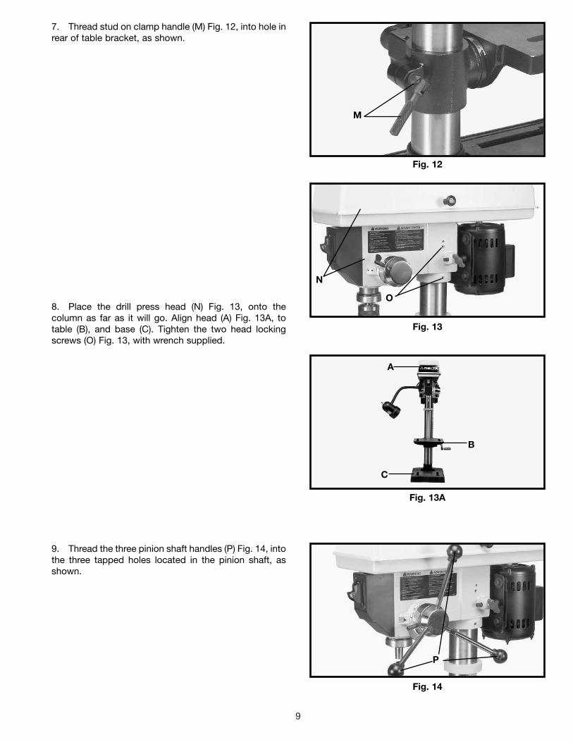
7. Thread stud on clamp handle (M) Fig. 12, into hole inrear of table bracket, as shown.
8. Place the drill press head (N) Fig. 13, onto thecolumn as far as it will go. Align head (A) Fig. 13A, totable (B), and base (C). Tighten the two head lockingscrews (O) Fig. 13, with wrench supplied.
9. Thread the three pinion shaft handles (P) Fig. 14, intothe three tapped holes located in the pinion shaft, asshown.
Fig. 13A
A
B
C
10
Fig. 15
Fig. 16
R
Q
S
T
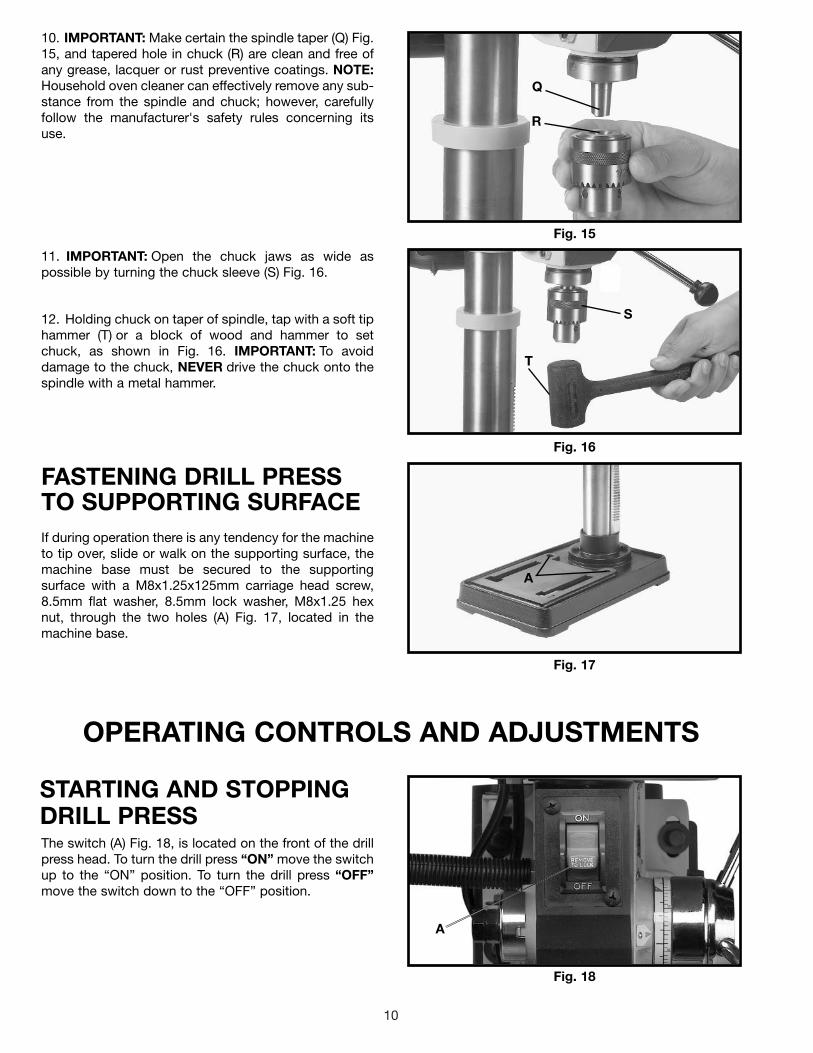
10. IMPORTANT: Make certain the spindle taper (Q) Fig.15, and tapered hole in chuck (R) are clean and free ofany grease, lacquer or rust preventive coatings. NOTE:Household oven cleaner can effectively remove any sub-stance from the spindle and chuck; however, carefullyfollow the manufacturer's safety rules concerning itsuse.
11. IMPORTANT: Open the chuck jaws as wide aspossible by turning the chuck sleeve (S) Fig. 16.
12. Holding chuck on taper of spindle, tap with a soft tiphammer (T) or a block of wood and hammer to setchuck, as shown in Fig. 16. IMPORTANT: To avoiddamage to the chuck, NEVER drive the chuck onto thespindle with a metal hammer.
FASTENING DRILL PRESSTO SUPPORTING SURFACEIf during operation there is any tendency for the machineto tip over, slide or walk on the supporting surface, themachine base must be secured to the supportingsurface with a M8x1.25x125mm carriage head screw,8.5mm flat washer, 8.5mm lock washer, M8x1.25 hexnut, through the two holes (A) Fig. 17, located in themachine base.
Fig. 17
A
OPERATING CONTROLS AND ADJUSTMENTS
STARTING AND STOPPINGDRILL PRESSThe switch (A) Fig. 18, is located on the front of the drillpress head. To turn the drill press “ON” move the switchup to the “ON” position. To turn the drill press “OFF”move the switch down to the “OFF” position.
Fig. 18
A

11
LOCKING SWITCH IN THE “OFF” POSITIONIMPORTANT: When the machine is not in use, theswitch should be locked in the “OFF” position to preventunauthorized use. This can be done by grasping theswitch toggle (B) and pulling it out of the switch, asshown in Fig. 19. With the switch toggle (B) removed,the switch will not operate. However, should the switchtoggle be removed while the drill press is operating, theswitch can be turned “OFF” once, but cannot berestarted without inserting the switch toggle (B). Fig. 19
TABLE ADJUSTMENTS1. The table can be raised or lowered on the drill presscolumn by loosening the table clamp (A) Fig. 20, andturning the table raising and lowering handle (B) Fig. 21.After the table is at the desired height, tighten clamp (A)Fig. 20. NOTE: Final positioning of the drill press tableshould always be from the bottom to the up position.
2. The table can be rotated 360 degrees on the columnby loosening clamp (A) Fig. 20, rotate table to desiredposition and tighten clamp (A).
Fig. 20
Fig. 21
A
B
B
Fig. 19A
FLEXIBLE LAMPThe flexible lamp operates independently of the drillpress. To turn the lamp “ON” and “OFF”, rotate switch(A) Fig. 19A.
WARNING: To reduce the risk of fire, use 40 watt orless, 120 volt, reflector track type light bulb (notsupplied). A standard household light bulb should not beused. The reflector track type light bulb should notextend below the lamp shade.
A

12
Fig. 22 Fig. 23
Fig. 24
3. The table can be tilted right or left by pulling out andremoving table alignment pin (C) Fig. 22. NOTE: If pin (C)is difficult to remove, turn nut (E) clockwise to pull pinout of casting.
4. Fig. 23, illustrates the table alignment pin (C)removed. Loosen table locking bolt (D), tilt table to thedesired angle and tighten bolt (D). When returning tableto the level position, replace table alignment pin (C). Thiswill position the table surface at 90 degrees to thespindle.
5. A tilt scale (E) Fig. 24, is provided on the tablebracket casting to indicate the degree of tilt. A witnessline and zero mark (F) are also provided on the table toline up with the scale (E).
C
D
ED
C
SPINDLE SPEEDSFive spindle speeds of 620, 1100, 1720, 2340 and 3100RPM are available with your drill press. Fig. 25, illustrateswhich step on the motor and spindle pulleys the beltmust be placed on to obtain the five speeds available.
SPINDLE MOTOR
3100
2340
1720
1100
620
Fig. 25
CHANGING SPEEDS ANDADJUSTING BELT TENSIONNOTE: A BELT POSITIONING SPEED CHART (E) FIG.26, IS LOCATED ON THE INSIDE TOP COVER OFTHE DRILL PRESS.
1. DISCONNECT MACHINE FROM POWER SOURCE.
2. Lift up the belt and pulley guard (A) Fig. 26.
3. Release belt tension by loosening tension lock knob(B) Fig. 26, and pivoting the motor (D) toward the front ofthe drill press.
4. While holding the motor toward the front of the drillpress, position the belt (C) on the desired steps of themotor and spindle pulleys, as shown in Fig. 26.
A
B
C
E
Fig. 26
D
FE

13
Fig. 27
DRILLING HOLES TO DEPTHWhere a number of holes are to be drilled to exactly thesame depth, a depth stop is provided in the pinion shafthousing and is used as follows:
1. DISCONNECT MACHINE FROM POWER SOURCE.
2. Insert bit into chuck.
3. Lower the spindle until the pointer (C) Fig. 27, linesup with the mark on the scale (D) you wish the depth ofthe holes to be drilled. Then tighten lock screw (A).Return the spindle to the up position.
4. Place the material to be drilled on the drill presstable. Raise the drill press table until the material to bedrilled just touches the drill bit.
5. Drill a test hole to check the adjustment and readjustif necessary. All holes will then be drilled to the exactdepth as indicated on scale (D) Fig. 27. NOTE: Scale (D)is calibrated in both inches and millimeters.
C A
B
D
ADJUSTING SPINDLERETURN SPRINGThe spindle is automatically returned to its upper mostposition when the handle is released. It is recommendedthat the handle be allowed to slowly return to the topposition after each hole has been drilled in the material.This spring has been properly adjusted at the factoryand should not be disturbed unless absolutelynecessary. To adjust the return spring, proceed asfollows:
1. DISCONNECT MACHINE FROM POWER SOURCE.
2. Loosen nuts (B) and (E) Fig. 28. Make sure springhousing (A) stays engaged with head casting.
3. While FIRMLY HOLDING spring housing (A) Fig. 29pull out housing and rotate it until boss (D) is engagedwith the next notch on the housing. Turn the housingcounterclockwise to increase or clockwise to decreasespring tension. Turn nut (E) until it contacts springhousing (A), then back nut (E) out a 1/4 turn from springhousing (A). Tighten nut (B) against nut (E), to hold thehousing in place. IMPORTANT: Inside nut (E) shouldnot contact spring housing (A) when tightened.
Fig. 28
Fig. 29
5. After the belt is positioned on the desired steps ofthe motor and spindle pulleys, move motor (D) Fig. 26,to the rear until the belt is properly tensioned and tightentension lock knob (B). The belt should be just tightenough to prevent slipping. Excessive tension willreduce the life of the belt, pulleys and bearings. Correcttension is obtained when the belt (C) can be flexedabout 1" out of line midway between the pulleys usinglight finger pressure.
BE
A
A
D
B
E

14
OPERATIONYour drill press is to be used with drill bits with a shank of 1/2" or less in diameter. The following will give the inexperiencedoperator a start on common drill press operations. Use scrap material for practice to get a feel of the machine beforeattempting regular work.
WARNING: The use of accessories and attachments not recommended by Delta may result in risk of injury.
IMPORTANT: When the workpiece is long enough itshould always be positioned on the table with one endagainst the left side of the column, as shown in Fig. 30.This prevents the workpiece from rotating with the drillbit or cutting tool, causing damage to the workpiece orpersonal injury to the operator. If it is not possible tosupport the workpiece against the column, theworkpiece should always be fastened to the table usingclamps or a vise.
Fig. 30
INSTALLING ANDREMOVING DRILL BITS1. DISCONNECT MACHINE FROM POWER SOURCE.
2. Insert smooth end of drill bit (A) Fig. 31, into chuck(B), as far as it will go, and then back the bit out 1/16",or up to the flutes for small bits.
3. Make certain that the drill bit (A) Fig. 31, is centeredin the chuck (B) before tightening the chuck with the key(C).
4. Turn the chuck key (C) Fig. 31, clockwise to tightenand counterclockwise to loosen the chuck jaws.
5. Tighten all three chuck jaws to secure the drill bitsufficiently so that it does not slip while drilling.
6. MAKE SURE chuck key (C) Fig. 31, is removed fromchuck before starting drill press. Your chuck key (C) isequipped with a self-ejecting pin (D) which helpsminimize the hazard of the key being left in the chuck.
Fig. 31
A
B
C
D

15
CORRECT DRILLING SPEEDSFactors which determine the best speed to use are: kind of material being worked, size of hole, type of drill or othercutter, and quality of cut desired.
WARNING: Use the recommended speed for the drill press bit and workpiece material.
BORING IN WOODTwist drills, although intended for metal drilling, may also be used for boring holes in wood. However, machine spur bitsare generally preferred for working in wood; they cut a flat bottom hole and are designed for removal of wood chips.Do not use hand bits which have a screw tip; at drill press speeds they turn into the wood so rapidly as to lift the workoff the table and whirl it.
For through boring, line up the table so that the bit will enter the center hole to avoid damage to the table. Scribe avertical line on the front of the column and a matching mark on the table bracket and the drill press head, so that thetable and drill press head can be clamped in the center position at any height.
Feed slowly when the bit is about to cut through the wood to prevent splintering the bottom face. Use a scrap pieceof wood as a base block under the work; this helps to reduce splintering and protects the point of the bit.
DRILLING METALUse clamps to hold the work when drilling metal. The work should never be held in the bare hand; the drill bit may seizethe work at any time, especially when breaking through the stock. If the piece is whirled out of the operator's hand, theoperator may be injured. The drill bit will be broken if the work strikes the column.
The work must be clamped firmly while drilling; any tilting, twisting or shifting results not only in a rough hole, but alsoincreases drill bit breakage. For flat work, lay the piece on a wooden base and clamp it firmly down against the tableto prevent it from turning. If the piece is of irregular shape and cannot be laid flat on the table, it should be securelyblocked and clamped.

Two Year Limited WarrantyDelta will repair or replace, at its expense and at its option, any Delta machine, machine part, or machine accessory whichin normal use has proven to be defective in workmanship or material, provided that the customer returns the productprepaid to a Delta factory service center or authorized service station with proof of purchase of the product within twoyears and provides Delta with reasonable opportunity to verify the alleged defect by inspection. Delta may require thatelectric motors be returned prepaid to a motor manufacturer’s authorized station for inspection and repair or replacement.Delta will not be responsible for any asserted defect which has resulted from normal wear, misuse, abuse or repair oralteration made or specifically authorized by anyone other than an authorized Delta service facility or representative. Underno circumstances will Delta be liable for incidental or consequential damages resulting from defective products. Thiswarranty is Delta’s sole warranty and sets forth the customer’s exclusive remedy, with respect to defective products; allother warranties, express or implied, whether of merchantability, fitness for purpose, or otherwise, are expresslydisclaimed by Delta.
Printed in U.S.A.
PARTS, SERVICE OR WARRANTY ASSISTANCEAll Delta Machines and accessories are manufactured to high quality standards and are serviced by a networkof Porter-Cable • Delta Factory Service Centers and Delta Authorized Service Stations. To obtain additionalinformation regarding your Delta quality product or to obtain parts, service, warranty assistance, or the locationof the nearest service outlet, please call 1-800-223-7278 (In Canada call 1-800-463-3582).
ACCESSORIESA complete line of accessories is available from your Delta Supplier, Porter-Cable • Delta Factory Service Centers,and Delta Authorized Service Stations. Please visit our Web Site www.deltamachinery.com for a catalog orfor the name of your nearest supplier.
WARNING: Since accessories other than those offered by Delta have not been tested with this product, use of such accessories could be hazardous. For safest operation, only Delta recommended accessories should be used with this product.
16