1 uml basic training. uml basic training2 agenda definitions: requirements, design basics of...
TRANSCRIPT

1
www.methoda.com
UML Basic Training

2UML Basic training
Agenda
Definitions: requirements, design
Basics of Unified Modeling Language 1.4
SysML extensions

3UML Basic training
Definitions
Requirement A description of the behavior of the system or part of
the system (sub-system, component) or a property of it
Design A representation (model) that describes how
something is going to be built
““All models are wrong. Some are All models are wrong. Some are useful”useful”
George Box George Box
““All models are wrong. Some are All models are wrong. Some are useful”useful”
George Box George Box

4UML Basic training
Types of R&D Engineering Activities
SW modeling
UML
HW modeling
VHDL, CAD, …
System modeling
SysMLRequirements definition &
management
SysML extends UML in order to support all system engineering methodology

5UML Basic training
The Basic Development Process
Requirements High level (system view) Review Detailed (per feature) Use case models Review
Design High level (system view) Design models Detailed (per unit/class/interface)
Code

6UML Basic training
Object Oriented Analysis and Design
OOAModel of requirements
(user view)
OODModel of design
(developer view)

7UML Basic training
UML - Unified Modeling Language
A graphical language for visualizing the structure
and behavior of systems and systems parts
Not a methodology. A language
Provides notation (symbols) and meaning
(semantics)
Developed by Object Management Group
(OMG)
Supported by many tools

8UML Basic training
Diagram Types in UML 1.x
Class, Object, Component
Package
Deployment
Use case
Sequence
Activity
Collaboration
State chart

9UML Basic training
Static and Dynamic Models
Static (structure): Class, Object, Component
Package
Deployment
Dynamic (behavior): Use case
Activity
Sequence
Collaboration
State chart

10UML Basic training
Use Case Diagram

11UML Basic training
Use cases (UC)
External view of the system
Expressed in user terms
Use case is used by an actor
Actor is not necessarily human. Can be other systems
Use case can: <<include/use>> other use case
<<extend>> other use case
Each UC is described using an activity diagram or
sequence diagram

12UML Basic training
Use Case Documentation
Title (goal)
Short description
Actors
Trigger
Pre-condition
Post-condition
Normal flow (steps) Using text and/or activity diagrams
Exceptional/alternate flows

13UML Basic training
Activity diagram
Describes logic of flow/process, sequence of actions
* (see later SysML extensions for activity diagrams)

14UML Basic training
Class Diagram
GeneralizationAssociation

15UML Basic training
Class Diagram Terms
Class Name
Attributes
Operations
Visibility: public (+), Private (-), Protected (#)

16UML Basic training
Class Diagram Terms
Relationships Dependency
Change to one may cause change to other Association
Connection exists between classes/objects Generalization
Abstract classes, inheritance Aggregation
Model of Whole/Part. Lifetime of whole & part not linked Composition
Model of Whole/Part. Lifetime of whole & part linked
Multiplicity: m..n, 1, 0..1, * Indicates how many objects may fill the relation

17UML Basic training
Interfaces
Distinguish between interface and the implementation
Abstract class has one or more operations that are abstract
Interface is a class with only abstract operations
*(In SysML “port” is used)

18UML Basic training
Object Diagram
Model specific instances derived from class
diagram

19UML Basic training
Package Diagram
Groups UML elements: By diagram types (other packages, diagrams,
classes, etc.)
By system hierarchy (structure): system, sub-
systems, etc.
In software: model namespaces in C++
and .NET

20UML Basic training
Sequence Diagram
Describes a set of objects that take part in a
flow/sequence
Shows data and behavior in one place
Time line is from top to bottom
Sequence diagrams can refer (ref) to other seq.
diagrams, can include alternative (alt) paths,
loops and more (not shown in the example).

21UML Basic training
Sequence Diagram

22UML Basic training
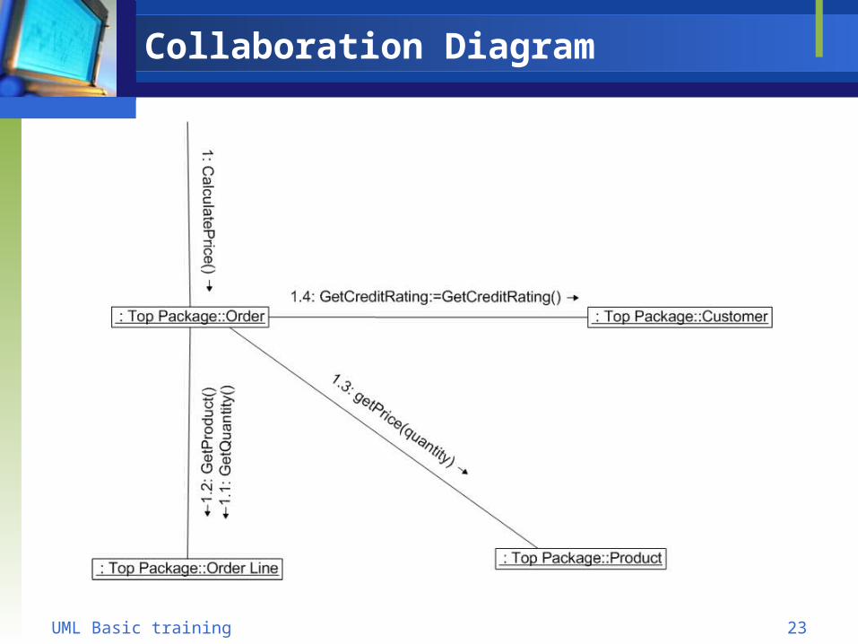
Collaboration Diagram
Describes a set of objects that take part in a
flow/sequence
Shows data and behavior in one place
Time is expressed by numbers on the
association lines
23UML Basic training
Collaboration Diagram

24UML Basic training
State Chart Diagram
Model dynamic aspect of an object, component
or a system
Terms: Initial state
States
Events
Transition activity
Final state

25UML Basic training
Component Diagram
Component is a replaceable SW part of the system
that implements a set of interfaces
Components can be used to define also sub-
systems
*(In SysML “block” is used)

26UML Basic training
Deployment Diagram
Model physical aspect of the system
SysML uses different notation (block diagrams
with <<allocation>>)

27UML Basic training
SysMLSystem engineering Modeling Language

28UML Basic training
UML & SysML
UML 2.0 contains many enhancements to
support systems engineering (SE)
BUT,
It doesn’t satisfy all SE needs
SysML extends UML 2.0
Adopted by Object Management Group in Feb-
2006
Not very popular yet

29UML Basic training
UML & SysML
UML 2
SysML
Not required by SysUML
UML reused by SysUML
SysUML extensions
SysML Extensions:
- Blocks
- Item flows
- Allocations
- Requirements
- Parametrics
- Continuous flows
…

30UML Basic training
SysML Diagrams

31UML Basic training
Example of Block Diagrams in SysML
A block element extends the UML Class element
A block can contain properties, ports,
operations, etc

32UML Basic training
Example of Block Diagrams in SysML

33UML Basic training
Activity in SysML

34UML Basic training
Activity Diagram in SysML

35UML Basic training
For more info
http://www.sparxsystems.com.au/resources/uml2_tutorial
http://omgsysml.org/INCOSE-2007-OMG-SysML-Tutorial.pdf

36UML Basic training
www.methoda.com