1. vector controller based speed control of induction motor drive with 3-level svpwm based...
TRANSCRIPT

8/10/2019 1. Vector Controller based Speed Control of Induction Motor Drive with 3-Level SVPWM based Inverter.pdf
http://slidepdf.com/reader/full/1-vector-controller-based-speed-control-of-induction-motor-drive-with-3-level 1/11
G. Subba Reddy 1
International Journal of Emerging Trends in Electrical and Electronics (IJETEE) Vol. 1, Issue. 4, March-2013.
Vector Controller based Speed Control of
Induction Motor Drive with 3-Level SVPWM
based Inverter
G. Subba Reddy
ABSTRACT: Vector control is becoming the industrial standard
for induction motor control. The vector control technique
decouples the two components of stator current space vector: one
providing the control of flux and the other providing the control
of torque. The two components are defined in the synchronously
rotating reference frame. With the help of this control technique
the induction motor can replace a separately excited dc motor.
The DC motor needs time to time maintenance of commutator,
brushes and brush holders. The main effort is to replace DC
motor by an induction motor and merge the advantages of both
the motors together into variable speed brushless motor driveand eliminate the associated problems. The squirrel cage
induction motor being simple, rugged, and cheap and requiring
less maintenance, has been widely used motor for fixed speed
application. So with the implementation of vector control,
induction motor replaces the separately excited dc motor. The
vector control technique is therefore a better solution so that the
control on flux and torque become independent from each other
and the induction motor is transformed from a non-linear to
linear control plant. With the advent of field oriented control; the
induction motor has become an attractive option. In this report
we will come to know the concept of vector control and different
types of vector control techniques available. And finally we will
be able to compare them.
Keywords : Induction Motor, SVPWM, Vectorl, 3-level
Inverter.
1. INTRODUCTION
Now a day’s more than 60% of all the electrical
energy generated in the world is used by cage induction
machines have been mostly used at fixed speed for more
than a century. An induction motor (IM) is a type of
asynchronous AC motor where power is supplied to the
rotating device by means of electromagnetic induction Onthe other hand, D.C machines have been used for variable
speed applications. Induction motors are widely used,
especially polyphase induction motors, which are frequently
used in industrial drives.
G Subba Reddy is working as Assistant Professor in Electrical andElectronics Engineering Department at V.R. Siddhartha Engineering
College, Vijayawada, Andhra Pradesh, India. Email: [email protected]
In DC machines mmf axis is established at 90˚
electrical to the main field axis. The electromagnetic torque
is proportional to the product of field flux and armature
current. Field flux is proportional to the field current and is
unaffected by the armature current because of orthogonalorientation between armature mmf and field mmf .Therefore
in a separately excited DC machine , with a constant value
of field flux the torque s directly proportional to the
armature current. Hence direct control of armature current
gives direct control of torque and fast response. Hence theyare simple in control and offer better dynamic responseinherently. Numerous economical reasons, for instance high
initial cost, high maintenance cost for commutators, brushes
and brush holders of DC motors call for a substitute which
is capable of eliminating the persisting problems in dc
motors. Freedom from regular maintenance and a brushless
robust structure of the three phase squirrel cage induction
motor are among the prime reasons, which brings it forward
as a good substitute. The history of electrical motors goes
back as far as 1820, when Hans Christian Oersted
discovered the magnetic effect of an electric current. One
year later, Michael Faraday discovered the electromagnetic
rotation and built the first primitive D.C. motor. Faradaywent on to discover electromagnetic induction in 1831, but
it was not until 1883 that Tesla invented the A.C.
asynchronous motor [1]. Currently, the main types of
electric motors are still the same, DC, AC asynchronous and
synchronous, all based on Oested, Faraday and Tesla’stheories developed and discovered more than a hundred
years ago.
An induction motor (IM) is a type of asynchronous
AC motor where power is supplied to the rotating device by
means of electromagnetic induction [2, 3]. Induction motors
are widely used, especially polyphase induction motors,
which are frequently used in industrial drives. These factsare due to the induction motors advantages over the rest of
the motors. Most of the industrial motor applications use AC
induction motors. The reasons for this include high
robustness, reliability, low price and high efficiency [2-4].
1.1. APPLICATIONS
A wide variety of induction motors are available
and are currently in use throughout a range of industrial
applications. Single phase induction motors are widely used,
due to their simplicity, strength and high performance. They
are used in household appliances, such as refrigerators, air
conditioners, hermetic compressors, washing machines, pumps, fans, as well as in some industrial applications.
Before the days of power electronics, a limited speed control

8/10/2019 1. Vector Controller based Speed Control of Induction Motor Drive with 3-Level SVPWM based Inverter.pdf
http://slidepdf.com/reader/full/1-vector-controller-based-speed-control-of-induction-motor-drive-with-3-level 2/11
G. Subba Reddy 2
International Journal of Emerging Trends in Electrical and Electronics (IJETEE) Vol. 1, Issue. 4, March-2013.
of IM was achieved by switching the three-stator windings
from delta connection to star connection, allowing the
voltage at the motor windings to be reduced [1-6].
1.2. VARIABLE-FREQUENCY DRIVES (VFD)
A VFD can easily start a motor at a lower frequency
than the AC line, as well as a lower voltage, so that the
motor starts with full rated torque and with no inrush of current. The rotor circuit's impedance increases with slip
frequency, which is equal to supply frequency for astationary rotor, so running at a lower frequency actually
increases torque [7]. Industries have many applications,
where variable operating speed is a prime requirement.
Principal benefits of variable speed drives in industrial
applications are that they allow the drive speed and torque to
be adjusted to suit the process requirements. In manyapplications, operating the plant at a reduced speed when
full output is not needed produces a further important
benefit: energy savings and reduced cost [7]. Whereas
infinitely variable speed drives with good performances for
DC motors already existed. These drives not only permittedthe operation in four quadrants but also covered a wide
power range. Moreover, they had a good efficiency, and
with a suitable control even a good dynamic response. Its
main drawback was the compulsory requirement of brushes
[4].
Scalar controllers: Despite the fact that “Voltage-
Frequency” (V/F) is the simplest controller, it is the most
widespread, being in the majority of the industrialapplications [2]. It is known as a scalar control and acts by
imposing a constant relation between voltage and frequency,
so as to give nearly constant flux over wide range of speed
variation [3]. More over Constant voltage/hertz controlkeeps the stator flux linkage constant in steady state without
maintaining decoupling between the flux and torque [2].However, this controller does not achieve a good accuracy
in both speed and torque responses, mainly due to the fact
that the stator flux and torque are not directly controlled.
Even though, as long as the parameters are identified, the
accuracy in the speed can be 2% (expect in a very low
speed), and the dynamic response can be approximately
around 50ms [2, 3].
2. INDUCTION MOTOR MATHMATICAL MODEL
The steady-state model and equivalent circuit are
useful for studying the performance of machine in steady
state. This implies that all electrical transients are neglected
during load changes and stator frequency variations. The
dynamic model of IM is derived by using a two-phase motor
in direct and quadrature axes [16]. This approach is
desirable because of the conceptual simplicity obtained with
the two sets of the windings, one on the stator and the other
on the rotor.
The equivalence between the three-phase and two-
phase machine models is derived from the simple
observation. The concept of power invariance is introduced
[2, 3, 8]. The reference frames are chosen to arbitrary and particular cases such as stationary, rotor, and synchronous
reference frames, are simple instances of the general case.
The space-phasor model is derived from the dynamic model
in direct and quadrature axes [16].
2.1 DYNAMIC d-q MODEL
The assumptions are made to derive the dynamic
model as uniform air gap, balanced rotor and stator
windings, with sinusoidal distributed mmf, inductance vs.rotor position in sinusoidal, and Saturation and parameter
changes are neglected.
The dynamic performance of an AC machine is
somewhat complex because the three-phase rotor windingsmove with respect to the three-phase stator windings as
shown in Fig 1(a). Basically, it can be looked on as a
transformer with a moving secondary, where the coupling
coefficients between the stator and rotor phases change
continuously with the change of rotor position
correspond to rotor direct and quadrature axes [2-4, 7, 8].
Note that a three-phase machine can be represented by anequivalent two-phase machine as shown in Fig 1(b), where
ds ~ qs correspond to stator direct and quadrature axes, and
d r ~q r is corresponding to rotor.
Although it is somewhat simple, the problem of time-
varying parameters still remains. R.H. Park, in the 1920s,
proposed a new theory of electric machine analysis to solvethis problem. Essentially, he transformed or referred, the
stator variables to a synchronously rotating reference frame
fixed in the rotor [17]. With such a transformation (called
Park’s transformation), he showed that all the time-varying
inductances that occur due to an electric circuit in relative
motion and electric circuits with varying magneticreluctances can be eliminated [3,7]. Later, in the 1930s, H.
C. Stanley showed that time- varying inductances in the
voltage equations of an induction machine due to electric
circuits in relative motion can be eliminated by
transforming the rotor variables to variables associated
with fictitious stationary windings. Later, G. Kron proposed
a transformation of both stator and rotor variables to a
synchronously rotating reference frame that moves with the
rotating magnetic field. D. S. Brereton proposed a
transformation of stator variables to a rotating reference
frame that is fixed on the rotor. In fact, it was shown later by
Krause and Thomas that time-varying inductances can be
eliminated by referring the stator and rotor variables to acommon reference frame which may rotate at any speed.
r

8/10/2019 1. Vector Controller based Speed Control of Induction Motor Drive with 3-Level SVPWM based Inverter.pdf
http://slidepdf.com/reader/full/1-vector-controller-based-speed-control-of-induction-motor-drive-with-3-level 3/11

8/10/2019 1. Vector Controller based Speed Control of Induction Motor Drive with 3-Level SVPWM based Inverter.pdf
http://slidepdf.com/reader/full/1-vector-controller-based-speed-control-of-induction-motor-drive-with-3-level 4/11
G. Subba Reddy 4
International Journal of Emerging Trends in Electrical and Electronics (IJETEE) Vol. 1, Issue. 4, March-2013.
csbsas
csbscsbsas
s
ds
s
qs
V aaV V
V V jV V V
jV V V
2
3
2
3
1
3
1
3
1
3
1
3
2
For convenience, the superscript e has been
dropped from now on from the synchronously rotating
frame parameters. Again, resolving the rotating frame
parameters into a stationary frame, the relations are.
(5)
(6)
The qe -de components can also be combined into a
vector form:
(7)
Or inversely
(8)
Note that the vector magnitudes in stationary and
rotating frames are equal, that is,
(9)
In Equation (7),e j
e
is defined as the inverse vector
rotator that converts ds -qs variables into de - qe variables.
The vector V and its components projected on rotating and
stationary axes are shown in Fig 3. The as-bs-cs variables
can also be expressed in vector form. And also:
(10)
Where a=e j 2∏ / 3. The parameters a and a 2can be
interpreted as unit vectors. Similar transformations can be
made for rotor circuit variables also [3, 8, 17].
2.3. SYNCHRONOUSLY ROTATING REFERENCE
FRAME - DYNAMIC MODEL.
For the two-phase machine shown in Fig 3, we need
to represent both ds -qs and dr – qr circuits and their
variables in a synchronously rotating de -qe frame. We can
write the following stator circuit equations:
(11)
s
ds
s
ds s
s
dsdt
d I RV (12)
Where and are q- axis and d-axis stator fluxlinkages, respectively. When these equations are converted
to de -qe frame, the following equations can be written:
(13)
qsedsds sdsdt
d I RV (14)
If the rotor is not moving, that is, , the rotor
equations for a doubly fed wound-rotor machine will be
similar to Equations (13) - (14):
(15)
qr edr dr r dr dt
d i RV (16)
The rotor actually moves at speed r , the d - q axes
fixed on the rotor move at a speed e - r relative to the
synchronously rotating frame. Therefore, rotor equations
should be modified as.
(17)
(18)
The de -qe dynamic model equivalent circuits that
satisfy Equations (13), (14) and (17), (18). A special
advantage of the de -qe dynamic model of the machine is
that all the sinusoidal variables in stationary frame appear as
dc quantities in synchronous frame. The flux linkage
expressions in terms of the currents can be written from Fig
3(b) as follows:
(19)
)( qr qsmqr lr qr ii Li L (20)
)( qr qsmqm ii L (21)
)( dr dsmdslsds ii Li L (22)
)( dr dsmdr lr dr ii Li L (23)
)( dr dsmdm ii L (24)
edseqs
s
qs V V V sincos
edseqs sds V V V cossin
ee j j s
ds
s
qs
e
s
dse
s
qse
s
dse
s
qsdsqs
e
qds
eV e jV V
V V jV V jV V V
)(
)cossin()sincos(
e jdsqs sds sqs e jV V jV V V
)(
22ˆdsqsm V V V V
s
qs
s
qs s
s
qsdt
d I RV
s
qs s
ds
dseqsqs sqsdt
d I RV
0r
dr eqr qr r qr dt
d i RV
dr r eqr qr r qr dt d i RV )(
qr r edr dr r dr dt
d i RV )(
)( qr qsmqslsqs ii Li L

8/10/2019 1. Vector Controller based Speed Control of Induction Motor Drive with 3-Level SVPWM based Inverter.pdf
http://slidepdf.com/reader/full/1-vector-controller-based-speed-control-of-induction-motor-drive-with-3-level 5/11
G. Subba Reddy 5
International Journal of Emerging Trends in Electrical and Electronics (IJETEE) Vol. 1, Issue. 4, March-2013.
Combining the above expressions with Equations
(13), (14), (17) and (18), the electrical transient model in
terms of voltages and currents can be given in matrix form
as
(25).
Where S is Laplace operator. For a cage motor,
Vrq=Vdr= 0. If the speed is considered constant. Then,
knowing the inputs Vsq, Vsd and , the currents iqs, ids,
iqr and idr can be solved from Equation (25). If the machine
is fed by current source, iqs, ids and are independent.
Then the dependent variables Vsq,Vsd, iqr and idr can be
solved from Equation (25). The speed in Equation (25)
cannot normally be treated as a constant. It can be related to
the torques as
(26)
Where TL = load torque, J = rotor inertia, and =
mechanical speed. Often, for compact representation, themachine model and equivalent circuits are expressed in
complex form [3]. Multiplying Equation (14) by –j andadding with Equation (13) gives.
(27)
Or
(28)
Similarly, the rotor equations (17)-(18) can be
combined to represent
qdr r eqdr qdr r qdr jdt
d i RV )( (29)
Where Vqdr=0. Therefore, the steady-state equations
can be derived as
(30)
(31)
If the parameter Rm is neglected. We know that
sin22
3r me I
P T
(32)
From Equation (32), the torque can be generally
expressed in the vector form as
(33)
dr qmqr dme I i P
T
22
3(34)
Some other torque expressions can be derived easily
as follows:
dsqmqsdme I i P
T
22
3(35)
dsqsqsdse I i P
T
22
3(36)
)(22
3qr dsdr qsme iiii L
P T
(37)
)(22
3dr I qr qr idr
P eT
(38)
Equations (25), (26), and (37) give the complete model
of the electro-mechanical dynamics of an IM in synchronousframe. Fig 4 shows the block diagram of the machine model
along with input voltage & output current transformation [2,
8] and resolving variables into dqe components.
3. 3-LEVEL INVERTER
Three-level inverters have attracted the attention of
researchers since their introduction by Nabae et al. [27] in
1981. Though simple and elegant, neutral-clamped circuit
topology has a few disadvantages. Neutral point fluctuation
is commonly encountered as the capacitors connected to
DC-bus carry load currents. Also, there is ambiguityregarding the voltage rating of the semiconductor devices,
which are connected to the neutral point. This calls for aconservative selection of devices for reliable operation,
which, however, increases cost. H-bridge topology [28, 29]
eliminates the problem of neutral fluctuation, but requires
three isolated power supplies. Diode clamped inverter
method alleviates the problem but does not eliminate it.
Three-Ievel inversion may also be achieved with two 2-level
inverters, driving an open-end winding induction motor
from either end [5], [6]. The inverters in this case require
isolated power supplies to eliminate the harmonic currents
of the triple order in the individual motor phases.
While two level-shifted triangular carrier waves are
generally employed to compare the modulating sine wave to
dr
qr
ds
qs
r r r r emmr e
r r er r mr em
mme s s se
mem se s s
dr
qr
ds
qs
i
i
i
i
SL R LSL L
LSL R LSL
SL LSL R L
LSL LSL R
V
V
V
V
)()(
)()(
r
e
e
r
dt
d J
P T
dt
d J T T r
Lm
Le
2
m
)()()( dsqsedsqsdsqs sdsqs j j jdt
d jii R jV V
qdsr eqdsqds sqds jdt
d i RV )(
se s s s j I RV
r er r j I
S
R 0
r me I x P
T
22
3

8/10/2019 1. Vector Controller based Speed Control of Induction Motor Drive with 3-Level SVPWM based Inverter.pdf
http://slidepdf.com/reader/full/1-vector-controller-based-speed-control-of-induction-motor-drive-with-3-level 6/11
G. Subba Reddy 6
International Journal of Emerging Trends in Electrical and Electronics (IJETEE) Vol. 1, Issue. 4, March-2013.
generate PWM signals for a 3-level Inverter [28], one
bipolar triangular carrier wave is sufficient for a 2-level
inverter, As mentioned earlier, one of the important
advantages of the proposed 3-level inverter is that it can be
operated as a 2-level inverter in the lower output voltagerange. This is accomplished by comparing the modulating
sine wave with only one triangular carrier wave for the
generation of PWM signals in the lower output voltage
range and with two triangular carrier waves in the higher output voltage range. To get a clear picture to facilitate the
explanation of the proposed SPWM strategy, the frequency
of the triangular carrier wave was chosen to be only 11
times that of the frequency of the modulating sine wave.
Also, to simplify the illustration of the concept of the
proposed SPWM strategy, it is assumed that the frequency
of the modulating sine wave is constant. But, in reality, it isvaried by the speed controller as in V/f control or the vector
control. Also, the frequency of the triangular carrier wave
will be significantly higher in practice.
Fig 4. Synchronously rotating frame machine models with input voltage and output current transformations.
In this paper, a sine-triangle PWM scheme is also
proposed for the inverter scheme. The scheme does not
require look-up tables to realize the switching sequences as
in the case of space vector modulation. Also, the switching
criterion that there should be only one switching of the
power devices of the constituent inverters during the
subinterval of the sampling time period is automatically
ensured in the sine-triangle PWM scheme [29]. The salient
features of the proposed scheme are(i) A new 3-level voltage source inverter, obtained by
cascading two 2-level inverters, is proposed in this
paper. The DC link capacitors of individual
inverters carry only the ripple currents and not the
load current. Hence the voltage fluctuations of the
neutral point are avoided in the proposed scheme.
However, three switches in the proposed schememust be rated to block the entire DC bus voltage.
.In the lower range of output voltage, 2-level
inversion can be achieved by switching only one
inverter and therefore the switching losses are
lower when compared to a conventional 3-level
inverter.
(ii) A modified sine-triangle-based PWM is also
presented in this paper. The scheme is capable of
ensuring a smooth changeover from 2- to 3-level
inversion mode and vice versa.
(iii) Simulation results indicate that the proposed
inverter scheme is capable of rendering good
performance in closed loop applications also.
(iv) This scheme may be extended to higher number of
levels also.
This Application Note reviews three level inverter
topology, often referred to as Neutral Point Clamped (NPC)
inverter. The three level inverter offers several advantagesover the more common two level inverter. As compared to
two level inverters, three level inverters have smaller output
voltage steps that mitigate motor issues due to long power
cables between the inverter and the motor. These issues
include surge voltages and rate of voltage rise at the motor
terminals and motor shaft bearing currents. In addition, thecleaner output waveform provides an effective switching
frequency twice that of the actual switching frequency.
Should an output filter be required, the components will besmaller and less costly than for an equivalent rated two level
8/10/2019 1. Vector Controller based Speed Control of Induction Motor Drive with 3-Level SVPWM based Inverter.pdf
http://slidepdf.com/reader/full/1-vector-controller-based-speed-control-of-induction-motor-drive-with-3-level 7/11
G. Subba Reddy 7
International Journal of Emerging Trends in Electrical and Electronics (IJETEE) Vol. 1, Issue. 4, March-2013.
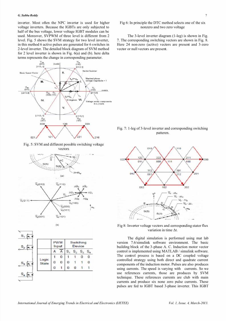
inverter. Most often the NPC inverter is used for higher
voltage inverters. Because the IGBTs are only subjected to
half of the bus voltage, lower voltage IGBT modules can be
used. Moreover, SVPWM of three level is different from 2
level. Fig. 5 shows the SVM strategy for two level inverter,in this method 6 active pulses are generated for 6 switches in
2-level inverter. The detailed block diagram of SVM method
for 2 level inverter is shown in Fig. 6(a) and (b). here delta
terms represents the change in corresponding parameter.
Fig. 5: SVM and different possible switching voltage
vectors
Fig 6: In principle the DTC method selects one of the six
nonzero and two zero voltage
The 3-level inverter diagram (1-leg) is shown in Fig.
7. The corresponding switching vectors are shown in Fig. 8.Here 24 non-zero (active) vectors are present and 3-zero
vector or null vectors are present.
Fig. 7: 1-leg of 3-level inverter and corresponding switching
patteren.
Fig 8: Inverter voltage vectors and corresponding stator fluxvariation in time Δt.
The digital simulation is performed using mat lab
version 7.6/simulink software environment. The basic
building block of the 3-phase A. C. Induction motor vector
control is implemented using MATLAB / simulink software.
The control process is based on a DC coupled voltage
controlled strategy using both direct and quadrate current
components of the induction motor. Pulses are also produces
using currents. The speed is varying with currents. So we
use references currents, those are produces by SVM
technique. These references currents are club with main
currents and produce six none zero pulse currents. These pulses are fed to IGBT based 3-phase inverter. This IGBT
8/10/2019 1. Vector Controller based Speed Control of Induction Motor Drive with 3-Level SVPWM based Inverter.pdf
http://slidepdf.com/reader/full/1-vector-controller-based-speed-control-of-induction-motor-drive-with-3-level 8/11
G. Subba Reddy 8
International Journal of Emerging Trends in Electrical and Electronics (IJETEE) Vol. 1, Issue. 4, March-2013.
based inverter out puts are ac voltages (but not a sinusoidal.
Because filters are not use in this model).
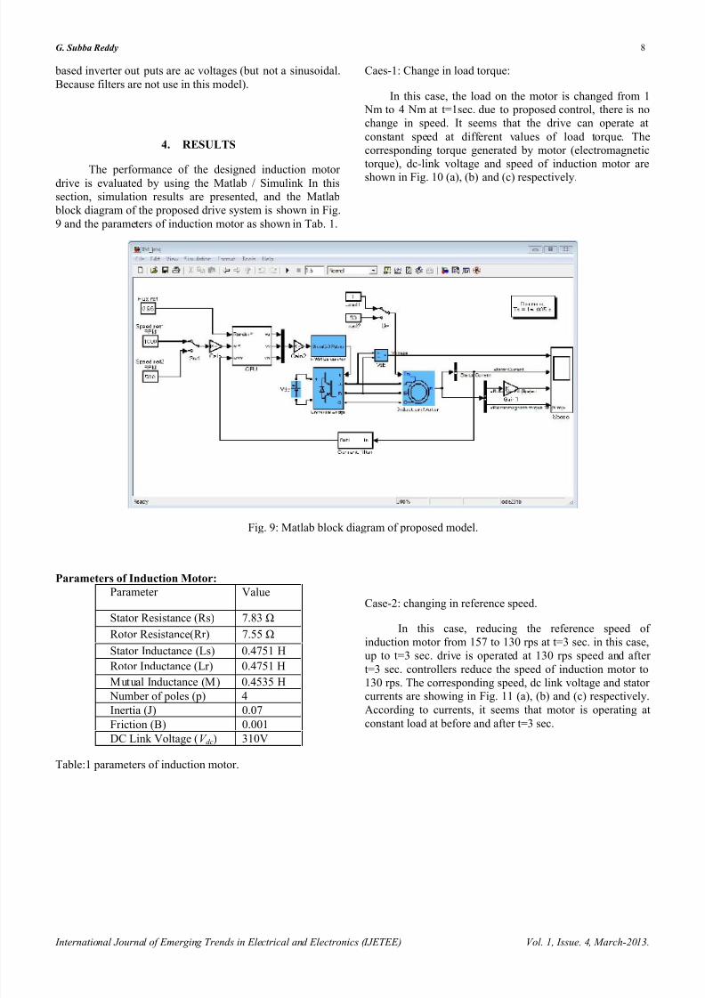
4. RESULTS
The performance of the designed induction motor drive is evaluated by using the Matlab / Simulink In this
section, simulation results are presented, and the Matlab
block diagram of the proposed drive system is shown in Fig.
9 and the parameters of induction motor as shown in Tab. 1.
Caes-1: Change in load torque:
In this case, the load on the motor is changed from 1 Nm to 4 Nm at t=1sec. due to proposed control, there is no
change in speed. It seems that the drive can operate at
constant speed at different values of load torque. The
corresponding torque generated by motor (electromagnetic
torque), dc-link voltage and speed of induction motor are
shown in Fig. 10 (a), (b) and (c) respectively.
Fig. 9: Matlab block diagram of proposed model.
Parameters of Induction Motor:
Parameter Value
Stator Resistance (Rs) 7.83 Ω
Rotor Resistance(Rr) 7.55 Ω
Stator Inductance (Ls) 0.4751 H
Rotor Inductance (Lr) 0.4751 H
Mutual Inductance (M) 0.4535 H
Number of poles (p) 4Inertia (J) 0.07
Friction (B) 0.001
DC Link Voltage (V dc) 310V
Table:1 parameters of induction motor.
Case-2: changing in reference speed.
In this case, reducing the reference speed of
induction motor from 157 to 130 rps at t=3 sec. in this case,
up to t=3 sec. drive is operated at 130 rps speed and after
t=3 sec. controllers reduce the speed of induction motor to
130 rps. The corresponding speed, dc link voltage and stator
currents are showing in Fig. 11 (a), (b) and (c) respectively.According to currents, it seems that motor is operating at
constant load at before and after t=3 sec.

8/10/2019 1. Vector Controller based Speed Control of Induction Motor Drive with 3-Level SVPWM based Inverter.pdf
http://slidepdf.com/reader/full/1-vector-controller-based-speed-control-of-induction-motor-drive-with-3-level 9/11

8/10/2019 1. Vector Controller based Speed Control of Induction Motor Drive with 3-Level SVPWM based Inverter.pdf
http://slidepdf.com/reader/full/1-vector-controller-based-speed-control-of-induction-motor-drive-with-3-level 10/11
G. Subba Reddy 10
International Journal of Emerging Trends in Electrical and Electronics (IJETEE) Vol. 1, Issue. 4, March-2013.
Fig. 11: (a) Speed of induction motor, (b) dc link voltage, (c) stator currents.
5. CONCLUSION
This paper presented Space vector pulse widthmodulation based 3 level inverter for vector controller based
induction motor drive. The main advantage in this proposed
method is incorporated vector control based induction motor control with multi level inverter. So that the advantages in 3-
level with SVPWM as increased the performance and life
time of drive. Extensive simulation results are presented
with different case studies. These advantages allow
implementing controllers for electric vehicles; because,
mainly electric vehicles need high starting torque so this is
produce the required torque with minimum torque ripplesand in electric vehicles, operation of drive is depends on
variable torque with constant speed applications as well as
variable speed with constant torque application. These two
types of application we are discussed in case-1 and case-2.
6. REFERENCES
[1] I.P. Kopylov, Mathematical Models of Electric Machines,
Translated from the Russian by P.S. Ivanov, Revised fromthe Russian edition, 1980.
[2] Bose B.K, Modern Power Electronics and AC Drives, 4thEdition, 2004.
[3] Bose B.K, Power Electronics and Motor Drives, AcademicPress, Imprint of Elsevier, 2006.

8/10/2019 1. Vector Controller based Speed Control of Induction Motor Drive with 3-Level SVPWM based Inverter.pdf
http://slidepdf.com/reader/full/1-vector-controller-based-speed-control-of-induction-motor-drive-with-3-level 11/11
G. Subba Reddy 11
International Journal of Emerging Trends in Electrical and Electronics (IJETEE) Vol. 1, Issue. 4, March-2013.
[4] B.L. Theraja, A.K. Theraja, A Textbook of Electrical
Technology, Vol.2.[5] G. K. Dubey, Power Semiconductor Controlled Drives,
Prentice Hall, Englewood, NJ, 1989.[6] B. K. Bose, Energy, environment, and advances in power
electronics, IEEE Trans. Power Electronics, vol. 15, pp. 688–
701, July 2000.[7] B. K. Bose (Ed.), Power Electronics and Variable Frequency
Drives, IEEE Press, New York, 1996.
[8] R. Krishnan, Electric Motor Drives, Modeling, Analysis, andControl, First Indian Reprint, Pearson Education, 2003.
[9] A.M. Trzynadlowski, Control of Induction Motors,
Academic Press, 2001.[10] I. Takahashi, Y. Ohmori, High-performance direct torque
control of induction motor, IEEE Trans. Ind. Appl., vol. 25,no. 2, pp. 257–264, 1989.
[11] A. M. Khambadkone and J. Holtz, Vector controlledinduction motor drive with a self- commissioning scheme,
IEEE Trans. Ind. Elec., vol. 38, pp. 322–327, October 1991.[12] P. Vas, Sensorless Vector and Direct Torque Control, Oxford
University Press, New York, 1998.[13] G. S. Buja and M. P. Kazmierkowski, Direct torque control
of PWM inverter-fed ac motors—a survey, IEEE IE Trans.,
vol. 51, pp. 744–757, August 2004.[14] P.Marino, M.D. Incecco and N.Visciano, A comparison of
Direct Torque Control Methodologies for Induction Motor,
IEEE trans. 2001.[15] G. Buja et al., Direct torque control of induction motor
drives, IEEE ISIE Conf. Rec., pp. TU2–TU8, 1997.[16] Burak Ozpineci, L.M.Tolbertr, Simulink Implementation of
Induction Machine Model-A modular approach, IEEE Trans.
2003.[17] R. H. Park, Two-reaction theory of synchronous machines-
generalized method of analysis -Part 1, AIEE Trans., vol. 48,
pp. 716–727, July 1929.[18] Xingyi.Xu, D.W.Novotny, Implementation of Direct stator
flux orientation control on versatile DSP based system, IEEE
Trans. Ind. Appl., vol. 24, no. 4, July/August 1991.[19] Y.A.Chapuis, D.Roye, J.Davoine, Principles andImplementation of Direct Torque Control by stator fluxorientation of Induction Motor, IEEE Trans. 1995.
[20] S.Vamsidhar, B.G.Fernades, Design and Development of
Energy Efficient Sensor less Direct Torque Controlled
Induction Motor Drive in Real Time Simulation, The 30thAnnual conference of IEEE Industrial Electronics Society November 2-6, 2004.
[21] S.Vamsidhar, B.G.Fernades, Hardware-in-loop-simulation
based design and experimental evaluation of DTC strategies,35th Annual IEEE power Electronics Special Conference,
2004.[22] C. Lascu, I. Boldea, F. Blaabjerg, A Modified Direct Torque
Control for Induction Motor Sensor less Drive. IEEE Tram
on Ind. Appl., vol 36, No-1, 122-130, January/ February2000.
[23] Hoang Le-Huy, Comparison of Field-Oriented Control and
Direct Torque Control for Induction Motor Drives, IEEE
Thirty-Fourth IAS Annual Meeting, 1999.[24] P. Z. Grabowski, M. P. Kazmierkowski, B. K. Bose, and F.
Blaabjerg, A simple direct-torque Neuro-fuzzy control of
PWM-inverter-fed induction motor drive, IEEE Trans. Ind.Elec., vol. 47, pp. 863–870, August 2000.
[25] G. C. D. Sousa, B. K. Bose, and K. S. Kim, Fuzzy logic
based on-line tuning of slip gain for an indirect vector
controlled induction motor drive, IEEE IECON Conf. Rec., pp. 1003–1008, 1993.
[26] B. K. Bose, Expert system, fuzzy logic, and neural network
applications in power electronics and motion control, Proc.IEEE, vol. 82, pp. 1303–1323, August 1994.
[27] A. Nabae, I. Takahashi, and H. Agaki, A new neutral-point-
clamped PWM inverter, IEEE Trans. IA.17, 518-523 (1981).[28] M. D. Manjrekar and A. Lipo, A hybrid multilevel inverter
topology for drive applications, /EEE-APEC-/998,California, pp. 523-529.
[29] A. Rufer, M. Veenstra and K. Gopakumar, Asymmetric
multilevel converter for high resolution voltage phasor generation, EPE'99, Lausanne, pp. PI-PI0.
[30] B. S. Suh and D. S. Hyun, A new N-level high voltage
inversion system, IEEE Trans., IE-44, 107-115 (1997).[31] H. Stemmler and P. Guggenbach, Configurations of high
power voltage source inverter drives, EPE Conf-/993,
Brighton, UK, pp. 7-12.[32] E. G. Shivakumar, K. Gopakumar and V. T. Ranganathan,
Space vector PWM control of dual inverter fed openendwinding induction motor drive, /EEE-APEC-200/ ,California, pp. 394-404.
[33] V. T. Somasekhar, K. Gopakumar Andre Pittet and V. T.
Ranganathan, A novel PWM switching strategy for a dualtwo-level inverter fed open-end winding induction motor drive, /EEE-PEDS 200/, Indonesia, pp. 196-202.
[34] Ned Mohan, T. M. Undeland and W. P. Robbins, Power
electronics-Converters, applications and design, Ch. 8,
second edition, Wiley (1995).[35] Joseph Vithayathil, Power electronics-Principles and
applications, Ch. 9, McGraw-Hill (1995).
[36] Peter Vas, Vector control of AC machines, Clarendon Press(1990).
G.Subba Reddy received hisBachelor degree in Electrical and
Electronics Engineering from PrasadV Potluri Siddhartha Institute Of Technology , Vijayawada (INDIA)
in 2006 and M.Tech in Power Systems from RVR&JC College Of Engineering, Acharya NagarunaUniversity Guntur, (INDIA) in 2008.He is currently working as an
Assistant Professor in Electrical and Electronics Engineering
Department at V.R.Siddhartha Engineering College Vijayawada,(INDIA). His research interests include Power Transmission,Distribution, protection and Digital Signal Processing.