1 the medium access control sublayer chapter 4. 2 the medium access control sublayer network...
Post on 20-Dec-2015
224 views
TRANSCRIPT

1
The Medium Access ControlSublayer
Chapter 4

2
The Medium Access ControlSublayer
• Network Classification 1. Use point-to-point connections - most WANs,
except satellite.
2. Use broadcast channels - most LANs.
• This chapter deals with broadcast networks and their protocol.
• The objective is to allocate the channel to: – maximize channel utilization, and – minimize channel access delay.

3
Channel Allocation
• Static Channel Allocation in LANs and MANs
• Dynamic Channel Allocation in LANs and MANs

4
Static Channel Allocation
• In static channel allocation, a subchannel is statically assigned to each station (computer or terminal).
• For example, in FDM, a frequency band is assigned to each station.
• This is inherently inefficient (w.r.t. channel utilization) for bursty traffic.
• Note, however, the channel access delay is minimal.

5
Static Channel Allocation
• We use the queueing system to analyze the above scheme.
• Single station case: Let C = channel capacity (in bps)
T = mean time delay to send one frame (in sec.) λ = arrival rate (in frames/sec.) 1/μ = mean frame size (in bits/frame)
From queueing theory, we obtain: T = 1 / (μ C - λ) For example, if 1/ μ = 10,000 bits/frame, C = 100
Mbps, and λ = 5000 frames/sec, then T = 1 / ((1/104)(108) - 5000) = 1 / 5000 = 200 μsec. per frame.

6
Static Channel Allocation
• N station case: Divide the channel up into N subchannels, each with
capacity C/N.
Let: λ /N = arrival rate at each station (divide the load).
Then, TFDM = 1 / (μ(C/N) - λ/N) = N / (μC - λ) = N T.
So, the N station case is N times worse than the 1 station case.
For example, as above, N = 10 TFDM = 2 msec. per
frame.

7
Dynamic Channel Allocation
• Assumptions: 1. Station Model – N independent stations generate
frames. 2. Single Channel – A single channel is available for
all communication. 3. Collision – Frames that overlap in time destroy
each other; this is called a COLLISION. All stations can detect collisions. The only errors are those caused by collisions.

8
Dynamic Channel Allocation
• Assumptions:4. Continuous Time means that transmission of
frames can begin at any time. Slotted Time means that time is divided into
discrete intervals, and frame transmission always begins at the start of a slot.
5. Carrier Sense means that stations can tell if the channel is in use by listening to the channel.
No Carrier Sense means that stations cannot tell if the channel is in use by listening to the channel.

9
Pure ALOHA
• In the Pure Aloha Protocol (by Abramson in 1970s), a station transmits the data whenever there is data to be sent. Then, the station listens to the channel to see if a collision occurred. If the frame was destroyed, the station waits for a random length of time and tries again.
• Systems in which multiple users share a common channel in a way that can lead to conflicts are widely known as contention systems.

10
Pure ALOHA
In pure ALOHA, frames are transmitted at completely arbitrary times.

11
Pure ALOHA - Analysis
• Let FRAME TIME be the time required to transmit a standard, fixed-length frame; that is, (1/μC).
• Assume there is an infinite population of stations that transmit frames according to a Poisson process with a mean of N frames transmitted per frame time.
• Note, if N>1, the channel will not be able to handle the load. So, we expect 0<N<1. The offered load, G, is the total number of frames sent on the channel per frame time; that is, G = N + (number of retransmissions per frame time).

12
Pure ALOHA - Analysis
• Let P0 = probability that no collisions occur during one frame time; that is, a transmission is successful. Then: the throughput, S = GP0
• Since the offered load is a Poisson distribution, with mean G, the probability that k frames are generated during a frame time is: Pr[k] = (Gk * e-G) / k!
• So, Pr[0] = e-G. The probability of no other traffic during the vulnerable period is e-G e-G = e-2G. Thus, P0 = e-2G, and it follows that S = Ge-2G
• dS/dG = e-2G (-2G + 1) = 0 G = 0.5• Note, the maximum occurs when G = 0.5. S = 0.184.

13
FYI: Poisson Distribution• The Poisson Distribution is used to model the number of
events occurring within a given time interval.
– It is often used to model events such as the number of telephone calls at a business or the number of accidents at an intersection in a specific time period.
– It is also useful in ecological studies, e.g., to model the number of prairie dogs found in a square mile of prairie.
• The formula for the Poisson probability mass function is:
p(x, λ) = e-λ λx / x! for x = 0, 1, 2, 3, ….
λ is a is the shape parameter which indicates the
average number of events in the given time interval.

14
FYI: Poisson Distribution• The following is the plot of the Poisson probability density
function for four values of λ.

15
Pure ALOHA
Vulnerable period for the shaded frame.

16
Slotted ALOHA
• In slotted Aloha (by Roberts in 1972) A computer is not permitted to send whenever a carriage return is typed but wait for a time slot.
• Time is divided into fixed slots of one frame time each. A station waits until the start of the next slot before transmitting a frame. Thus, P0 = e-G (the vulnerable period is only one time slot). S = G e-G Note that as G increases, the number of collisions increases exponentially.
• Note, the maximum occurs when G = 1. S = 0.368.• Slotted Aloha can be used to allocate a shared cable
channel.

17
Pure ALOHA
Throughput versus offered traffic for ALOHA systems.

18
Carrier Sense Multiple Access (CSMA) • Protocols in which stations listen for a carrier (i.e.
transmission) and act accordingly are called carrier sense protocols.
1. 1-persistent CSMA Channel Busy Continue sensing until free and then grab. Channel Idle Transmit with probability 1. Collision Wait for a random length of time and try again.
2. nonpersistent CSMA: Channel Busy Does not continually sense the channel. Wait
for a random length of time and try again. Channel Idle Transmit. Collision Wait for a random length of time and try again.

19
Carrier Sense Multiple Access (CSMA) 3. p-persistent CSMA: Channel Busy Continue sensing until free (same as idle). Channel Idle Transmit with probability p, and defer
transmitting until the next slot with probability q = 1-p. Collision Wait for a random length of time and try again. • The nonpersistent CSMA has better channel utilization but
longer delays than 1-persistent CSMA.• CSMA are an improvement over ALOHA because they ensure
that no station begins to transmit when it senses the channel busy.
• Another improvement is for stations to abort their transmissions as soon as they detect a collision. Quickly terminating damaged frames saves time and bandwidth. This protocol is called CSMA/CD (CSMA with Collision Detection).

20
Persistent and Nonpersistent CSMA
Comparison of the channel utilization versus load for various random access protocols.

21
CSMA with Collision Detection
CSMA/CD can be in one of three states: contention, transmission, or idle.

22
CSMA with Collision Detection• Stations detect collisions using analog hardware
and abort transmissions immediately.• Let τ be the propagation delay (the time for a
signal to propagate between the two farthest stations be τ). The contention interval is modeled as a slotted Aloha system with slot width 2τ.
• Then, 2τ is the time required for a station to detect collision with certainty.
For example, on a 1-km long coaxial cable, τ = 5 μsec. 2τ = 10 μsec to detect a collision.

23
Collision-Free Protocols• Assumptions:
– There are N stations, uniquely numbered 0, 1, 2, …, N – 1. – Each contention period consists of N slots.– Data frames consist of d time units.
1. Basic Bit-Map Protocol– Low load bit map is simply repeated over and over.
• Low # stations: wait ~ 1.5N slots• High # stations: wait ~ 0.5N slots
– The overhead to transmit a data frame is N bits. The channel efficiency at low load is d/(N + d)
– The channel efficiency at high load dN /(N + dN) = d/(1 + d)
2. Binary Countdown – stations overwrite the low numbered stations, and low numbered stations give up.

24
Collision-Free Protocols
The basic bit-map protocol.

25
Collision-Free Protocols
The binary countdown protocol. A dash indicates silence.

26
Limited-Contention Protocols• Contention Limited Collision free
(CSMA) contention (Binary Countdown)
small delay for Good channel efficiency
low load stations at high load• Analysis: Contention protocols (symmetric case)
Let k = # of stations
P = prob. that one station successfully requires the channel during a given slot.
ρ = prob. that a station transmits a frame during a given slot.

27
Limited-Contention Protocols• Analysis: Contention protocols (Symmetric case)
P = kρ(1 – ρ)k-1
↓
prob. That the other stations do not transmit
dP/dρ = –kρ(k – 1)(1 – ρ)k-2 + k(1 - ρ)k-1
= k(1 – ρ)k-2 [(ρ(k – 1) + (1 – ρ)]
= k(1 – ρ)k-2 (-ρk + ρ + 1 – ρ) = 0
ρk = 1 ρ = 1/k
P = k (1/k)(1 – 1/k)k-l = [(k – 1)/k]k-1 (4.4)

28
Limited-Contention Protocols
Acquisition probability for a symmetric contention channel.

29
Limited-Contention Protocols
• Idea: Limit the number of stations contending for a slot.
• Question: How to assign stations to a slot?
• Static assignment:One station/slot (group) Binary countdown
Two stations/slot P = 1 – ρ2 ≈ 1
(ρ 0 collision is small)
All stations/slot Slotted ALOHA

30
Adaptive Tree Walk Protocol• Use the algorithm devised by U.S. Army test for
syphilis in 1943)• Example: There are 8 stations. Suppose that stations 0,
2, 4, and 5 want to transmitSlot 0 – All try CollisionSlot 1 B Subtree try CollisionSlot 2 D Subtree try No collision – 0Slot 3 E Subtree try No collision – 2Slot 4 C Subtree try CollisionSlot 5 F Subtree try CollisionSlot 6 4Slot 7 5Slot 8 G Subtree try No Collision

31
Adaptive Tree Walk Protocol
The tree for eight stations.

32
Wavelength Division Multiple Access Protocols
• Each station is assigned two channels: a narrow band control channel and a wide band data channel.
• Each channel is divided into groups of time slots. All channels are synchronized by a single global clock.
• The protocol support three traffic classes:1. Constant data rate connection-oriented traffic such as
uncompressed video.2. Variable data rate connection-oriented traffic such as file
transfer.3. Datagram traffic such as UDP packet-oriented traffic.

33
Wavelength Division Multiple Access Protocols
Wavelength division multiple access.

34
Wireless LAN Protocols• Because signal strength is not uniform throughout the space in
which wireless LANs operate, carrier detection and collision may fail in the following ways: - Hidden nodes:
• Hidden stations: Carrier sensing may fail to detect another station. For example, A and D.
• Fading: The strength of radio signals diminished rapidly with the distance from the transmitter. For example, A and C.
- Exposed nodes: • Exposed stations: B is sending to A. C can detect it. C might want to
send to E but conclude it cannot transmit because C hears B.• Collision masking: The local signal might drown out the remote
transmission.
• The result scheme is carrier sensing multiple access with collision avoidance (CSMA/CA).

35
Wireless LAN configuration
LAN
Server
WirelessLAN
Laptops
Base station/access point
Palmtop
radio obstruction
A B C
DE

36
Wireless LAN Protocols
A wireless LAN. (a) A transmitting. (b) B transmitting.
• Hidden station problem: A is transmitting to B. C cannot hear A. If C starts transmitting, it will interfere at B.
• Exposed station problem: B is transmitting to A. C concludes that it may not send to D but the interference exists only between B and C.

37
MACA and MACAW• The sender transmits a RTS (Request To Send) frame.• The receiver replies with a CTS (Clear To Send)
frame.• Neighbors
– see CTS, then keep quiet.– see RTS but not CTS, then keep quiet until the CTS is back
to the sender.• The receiver sends an ACK when receiving an frame.
– Neighbors keep silent until see ACK.• Collisions
– There is no collision detection.– The senders know collision when they don’t receive CTS.– They each wait for the exponential backoff time.
• MACAW (MACA for Wireless) is a revision of MACA.

38
Wireless LAN Protocols
The MACA protocol. (a) A sending an RTS to B.
(b) B responding with a CTS to A.

39
Ethernet• Ethernet Cabling• Manchester Encoding• The Ethernet MAC Sublayer Protocol• The Binary Exponential Backoff Algorithm• Ethernet Performance• Switched Ethernet• Fast Ethernet• Gigabit Ethernet• IEEE 802.2: Logical Link Control• Retrospective on Ethernet

40
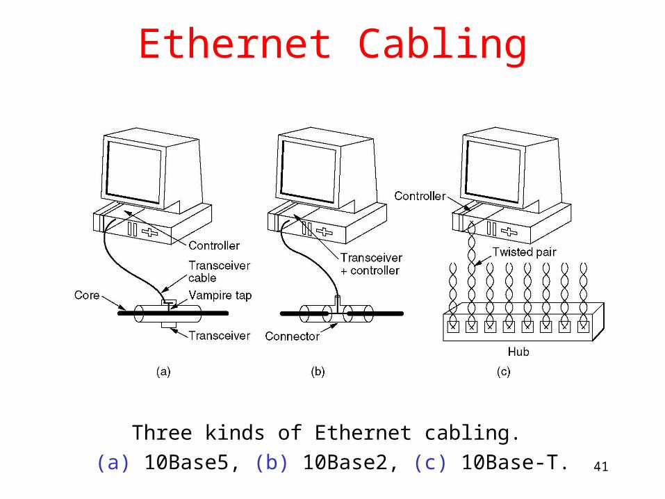
Ethernet Cabling
The most common kinds of Ethernet cabling.
• 10Base2 means that is operates at 10 Mbps, uses baseband signaling, and support segments up to 200 meters.
• 10Base-T became dominant due to its use of existing wiring and the ease of maintenance .
41
Ethernet Cabling
Three kinds of Ethernet cabling.
(a) 10Base5, (b) 10Base2, (c) 10Base-T.

42
Ethernet Cabling
Cable topologies. (a) Linear, (b) Spine, (c) Tree, (d) Segmented.
• Different ways of wiring a building are shown as follows:

43
Ethernet Cabling
• Devices used for connecting Ethernet cable:– A repeater is a physical layer device that receives,
amplifies and retransmits the signal.– A hub will take a network packet and transmit it to
all other ports on the hub. – A switch will take a network packet and transmit it
only to a specific port on the switch that the packet is addressed to. So, a switch greatly reduces network transmissions thus providing better network throughput.

44
Ethernet Cabling
(a) Binary encoding, (b) Manchester encoding, (c) Differential Manchester encoding.
• All Ethernet systems use Manchester encoding due to its simplicity (high at 0.85 V and low at -0.85 V).

45
Ethernet MAC Sublayer Protocol
Frame formats. (a) DIX Ethernet, (b) IEEE 802.3.
• Preamble – used for sender and receiver to synchronize their clock.
• Addresses– unique, 48-bit unicast address assigned to each adapter
– example: 8:0:e4:b1:2– broadcast: all 1s, the set of all recipient nodes
– Multicast: first bit is 1,a group of recipient nodes

46
Ethernet Transmit Algorithm
• If line is idle:– send immediately– upper bound message size of 1500 bytes– must wait some time (9.6µs) between back-to-back
frames• If line is busy:
– wait until idle and transmit immediately– called 1-persistent (a frame to send transmits with
probability 1)

47
The Binary Exponential Backoff Algorithm• If collision
– Time is divided into discrete slots whose length is equal to the worst-case round-trip propagation time on the ether (2τ).
• minimum frame is 64 bytes (header + 46 bytes of data) = 512 bits
• Channel capacity 10 Mbps, 512/10 M = 51.2µ
– delay and try again (binary exponential backoff)• 1st time: waits 0 or 1 slotted time (51.2µs)
• 2nd time: waits 0, 1, 2, or 3 slotted time
• nth time: k slotted time, for randomly selected k=0..2n - 1
• Frozen at 1023 slots and give up after several tries (usually 16)

48
Ethernet MAC Sublayer Protocol
Collision detection can take as long as 2 .

49
Ethernet Performance
Efficiency of Ethernet at 10 Mbps with 512-bit slot times.

50
Switched Ethernet
A simple example of switched Ethernet.
• To deal with increased load, the switched Ethernet is devised with a switch to route the frame to the destination.

51
Fast Ethernet
The original fast Ethernet cabling.
• The 802.3 committee decided to keep 802.3 for the fast Ethernet (802.3u).– Backward compatible– A new protocol might have problems.– Get job done before the technology changed.
• 100Base-T4 – 4 twisted pairs achieve 100 Mbps.

52
Gigabit Ethernet• 802.3z is the standard for gigabit Ethernet.• All configurations of gigabit Ethernet are point-to-
point rather than multidrop with two possible configurations:– Two computers are directly connected to each other.– Multiple computers are connected through a switch
and a hub.• Two operation mode:
– Full-duplex – connected by a switch. CSMA/CD is not used.– Half-duplex – connected by a hub.
• 802.3z increase the radius by carrier extension (padding to extend the frame to 512 bytes).
• Gigabit Ethernet supports flow control.• 802.3ae is 10-gigabit Ethernet standard.

53
Gigabit Ethernet
(a) A two-station Ethernet. (b) A multistation Ethernet.

54
Gigabit Ethernet
Gigabit Ethernet cabling.

55
IEEE 802.2: Logical Link Control
• All Ethernet protocols offer a best-efforts datagram service.
• LLC (Logical Link Control) forms the upper half of the data link layer. MAC forms the lower sublayer.– error-controlled, flow-controlled
– Adds an LCC header, containing sequence and acknowledgement numbers.
• LLC provides three service options:– Unreliable datagram service
– Acknowledged datagram service
– Reliable connection-oriented service

56
IEEE 802.2: Logical Link Control
(a) Position of LLC. (b) Protocol formats.

57
Retrospective on Ethernet
• Ethernet has been around for over 20 years.• The main reason for its success is simple and flexible.
– Simple translates into reliable, cheap, and easy to maintain.
• IP is a connectionless protocol, so it fits perfectly with Ethernet. IP fits much less well with ATM.
• Ethernet evolves with time. FDDI, Fibre Channel, and ATM were faster when introduced, but they are incompatible with Ethernet, complex, and hard to manage. Only ATM is used within the telephone system.

58
Wireless LANs
• The 802.11 Protocol Stack
• The 802.11 Physical Layer
• The 802.11 MAC Sublayer Protocol
• The 802.11 Frame Structure
• Services

59
802.11 Physical Layers
• IEEE 802.11 physical layers:– Infrared – 1 Mbps and 2 Mbps– FHSS (Frequency Hopping Spread Spectrum) uses
79 channels, each 1 MHz wide, starting in the 2.4 GHz band.
• A psudorandom number generator is used to produce the sequence of frequencies hopped to.
• The amount of time spent at each frequency, dwell time, is adjustable.
– DSSS (Direct Sequence Spread Spectrum) delivers 1 or 2 Mbps in the 2.4 GHz band.

60
802.11 Physical Layers
• IEEE 802.11 physical layers:– 802.11a uses OFDM (Orthogonal Frequency
Division Multiplexing) to deliver up to 54 Mbps in the 5 GHz band.
– 802.11b uses HR-DSSS (High Rate Direct Sequence Spread Spectrum) to achieve 11 Mbps in the 2.4 GHz band.
– 802.11g uses OFDM to achieve 54 Mbps in the 2.4 GHz band.

61
The 802.11 Protocol Stack
Part of the 802.11 protocol stack.

62
Wireless LAN Standard
Standard Modulation Spectrum Max physical Rate
Working distance
802.11 WDM, FHSS
DSSS
2.4 GHz 2 Mbps ≈100 m
802.11a OFDM 5 GHz 54 Mbps ≈ 50 m
802.11b HR-DSSS 2.4 GHz 11 Mbps ≈ 200 m
802.11g OFDM 2.4 GHz 54 Mbps ≈ 200 m

63
Wireless LANS Devices
a)wireless router b) wireless network card

64
802.11 MAC Sublayer
• Problems: Hidden and exposed stations• 802.11 supports two modes of operation:
– DCF (Distributed Coordination Function) does not use any kind of central control.
– PCF (Point Coordination Function) uses the base station to control all activity in its cell. Optional.
• CSMA/CA (CSMA with Collision Avoidance) is based on MACAW.– Use NAV (Network Allocation Vector) to indicate
the channel is busy.

65
The 802.11 MAC Sublayer Protocol
(a) The hidden station problem.(b) The exposed station problem.

66
The 802.11 MAC Sublayer Protocol
The use of virtual channel sensing using CSMA/CA.

67
The 802.11 MAC Sublayer Protocol
A sequence of fragments is called a fragment burst.
• The deal with the problem of noisy channels, 802.11 allows frames to be fragmented.

68
The 802.11 MAC Sublayer Protocol
• In the PCF mode, the base station polls the other stations, asking them if they have any frames to send.– Completely controlled by the base station. No collisions
occur.
– A beacon frame which contains system parameters is periodically (10 to 100 times per second) broadcasted to invite new stations to sign up for polling service.
• PCF and DCF can coexist within one cell by carefully defining the interframe time interval.

69
The 802.11 MAC Sublayer Protocol
• The four intervals are depicted:– SIFS (Short InterFrame Spacing) is used to allow the
parties in a single dialog the chance to go first including letting the receiver send a CTS and an ACK and the sender to transmit the next fragment.
– PIFS (PCF InterFrame Spacing) is used to allow the base station to send a beacon frame or poll frame.
– DIFS (DCF InterFrame Spacing) is used to allow any station to grab the channel and to send a new frame.
– EIFS (Extended InterFrame Spacing) is used only by a station that has just received a bad or unknown frame to report the bad frame.

70
The 802.11 MAC Sublayer Protocol
Interframe spacing in 802.11.

71
802.11 MAC Sublayer
• Three different classes of frames: data, control, management.
• The fields of data frame:– Frame control – 2 bytes and 11 subfields– Duration – 2 bytes indicate how long the frame and its
acknowledgement will occupy the channel– Addresses – 24 bytes identify source and destination
addresses and source and destination addresses of base stations
– Sequence – 12 bits identify the frame and 4 identify the fragment
– Data – the payload up to 2312 bytes– Checksum – 4 bytes

72
802.11 MAC Sublayer• The Frame control field:
– Version – allows two versions of the protocol operating at the same time
– Type – data, control, management– Subtype – RTS, CTS– To/Frame DS indicate the frame is going to or coming from
the intercell distribution– MF – more fragments will follow– Retry – marks a retransmission frame– Power management – puts the receiver into sleep stateor take
it out of sleep state– The W bit specifies that the frame body has been encrypted
using the WEP (Wired Equivalent Privacy) algorithm.– The O bit tells a sequence of frames with this bits must be
processed strictly in order.

73
The 802.11 Frame Structure
The 802.11 data frame.

74
802.11 Services• Distribution Services
– Association – mobile stations connect themselves to base stations
– Disassociation – the station or base station breaks the association
– Reassociation – a station may change its preferred base station
– Distribution – determines how to route frames sent to the base station
– Integration – handles the translation from the 802.11 format to the format of the destination network

75
802.11 Services
• Intracell Services– Authentication – a station must authenticate itself
before permitted to send data. – Deauthentication – a authenticated station wanting
to leave the network is deauthenticated.– Privacy – manages the encryption and decryption.
The algorithm specified is RC4 by Ronald Rivest of MIT.
– Data Delivery – not reliable.

76
Broadband Wireless
• Comparison of 802.11 and 802.16
• The 802.16 Protocol Stack
• The 802.16 Physical Layer
• The 802.16 MAC Sublayer Protocol
• The 802.16 Frame Structure

77
Comparison of 802.11 and 802.16• Similarity - Provide high-bandwidth wireless
communications.• Differences
• 802.16 provides service to stationary buildings which can have multiple computers. High quality full-duplex link is used. Higher cost is affordable. 802.11 provides service to individual mobile users.
• Longer transmission range security/privacy
• More user in each cell more spectrum is needed, operate in 10-66 GHz absorbed by water

78
The 802.16 Protocol Stack• Physical layer
– Physical medium dependent sublayer – narrow-band radio (which means that it contains all of its power in a very narrow portion of the radio frequency bandwidth, prone to interference ) is used with conventional modulation schemes.
– Transmission convergence sublayer – hide the different physical medium technologies from the data link layer.
• Data link layer– Security layer – deal with privacy and security
– MAC sublayer common part – channel management
– Service specific convergence sublayer – integrate with both datagram protocols (PPP, IP, and Ethernet) and ATM.

79
The 802.16 Protocol Stack
The 802.16 Protocol Stack.

80
The 802.16 Physical Layer
• Physical media:– 10-to-66 GHz millimeter waves travel in the straight line. – Transfer up to 155 Mbps– 30 miles range
• The base station has multiple antennas, each pointing at a different sector.
• The signal-to-noise ratio drops sharply with distance. Three modulation schemes are used depending on distance: – QAM-64 (6 bits/baud)– QAM-16 (4 bits/baud)– QPSK (2 bits/baud)

81
The 802.16 Physical Layer
The 802.16 transmission environment.

82
Broadband Wireless

83
The 802.16 Physical Layer• Unlike equal bandwidth allocation in the cell phone
system, more bandwidth is allocated for downstream than upstream traffic.
• Two schemes are used to allocate the bandwidth:– FDD (frequency division duplex)
– TDD (time division duplex) – downstream, guard, and upstream time slots
• The Hamming code is used for forward error correction.

84
The 802.16 Physical Layer
Frames and time slots for time division duplexing.

85
The 802.16 MAC Sublayer Protocol• Base station sends out frames• Each frame includes a number of subframes, which
include a number of time slots• The first two subframes are the downstream and
upstream maps, which tell what is in which time slot.• Downstream subframes (channels) are straight
forward. The base station decides what to send• Upstream channel is more complex, due to
competition.

86
The 802.16 MAC Sublayer Protocol• Four classes of service are defined and are connection-
oriented:– Constant bit rate service: transmit uncompressed voice
(similar to a T1 channel). Certain time slots are dedicated to each user.
– Real-time variable bit rate service: compressed multimedia and other soft real-time applications (bandwidth needed at each instant may vary). Polling is used.
– Non-real-time variable bit rate service: e.g., file transfer. • User can request a poll to send constant rate• If a station does not respond to a poll K times, the base station put it in
a multicast group. The user will content for service.– Best efforts service
• No polling. User compete for channel in the time slots marked inthe upstream map for contention.
• If a request is successful, it will be noticed in the next downstream map.

87
The 802.16 MAC Sublayer Protocol• Generic frame:
– EC: tells whether the payroll is encrypted
– Type: frame type (fragmentation)
– CI: whether checksum presents (optional as FEC in physical layer)
– EK: which encryption key is used
– Length: complete length including header
– Connection ID: which connection this frame belongs to
– CRC: checksum over header only
• Bandwidth request frame: indicate bytes needed

88
The 802.16 Frame Structure
(a) A generic frame. (b) A bandwidth request frame.

89
Bluetooth
• Bluetooth Architecture
• Bluetooth Applications
• The Bluetooth Protocol Stack
• The Bluetooth Radio Layer
• The Bluetooth Baseband Layer
• The Bluetooth L2CAP Layer
• The Bluetooth Frame Structure

90
Bluetooth• In 1994, Ericsson was interested in connecting mobile
phone with other devices without cables• Started by Ericsson, a SIG was formed with four other
companies (IBM, Intel, Nokia, and Toshiba) to develop a wireless standard for short range, low power, and inexpensive wireless radios.
• This project was named as Bluetooth, after Harald Blaatand (Bluetooth), a Viking king who unified Denmark and Norway, also without cable
• In 1999, 1500 page specification of V1.0• IEEE 802.15 adopts the Bluetooth as a personal area
network standard.

91
Bluetooth Architecture• The basic unit of Bluetooth is piconet, including a
master node, and up to seven active slave nodes within 10 m, and up to 255 parked nodes
• Multiple piconets can coexist. An interconnected collection of piconets is called a scatternet.

92
Bluetooth Architecture
Two piconets can be connected to form a scatternet.

93
Bluetooth Applications
The Bluetooth profiles.

94
The Bluetooth Protocol Stack• The Bluetooth Protocol Stack does not follow OSI
model and revised by IEEE to fix 802.11.• The Physical Radio layer corresponds to the ISO
physical layer and deals with radio transmission and modulation.
• The Baseband layer corresponds to MAC sublayer and some physical layer and handles how the master control time slots.
• The link manager handles establishment of logic channel (power management, authentication, QoS).
• The logical link control adaptation protocol (L2CAP) shields the upper layer from lower layer

95
The Bluetooth Protocol Stack• Audio and Control protocols deal with audio and
control.• LLC (Logical Link Control) is inserted by IEEE to
make it compatible with other 802.• RFcomm (Radio Frequency communication) emulates
serial port for connecting mouse, keyboard, modem.• Telephony protocol real-time speech, call setup and
termination• The service discovery protocol is used to locate service
in a network.• Each application uses a specific subset of protocols

96
The Bluetooth Protocol Stack
The 802.15 version of the Bluetooth protocol architecture.

97
The Bluetooth Frame Structure
• The address field identifies which of the eight active devices the frame is intended for.
• The type field identifies the frame type.• The flow bit is asserted by a slave when its buffer is
full.• The acknowledge bit is used to piggyback an ACK.• The sequence bit is used to number the frames to detect
retransmissions.

98
The Bluetooth Frame Structure
A typical Bluetooth data frame.

99
Data Link Layer Switching
• Bridges from 802.x to 802.y
• Local Internetworking
• Spanning Tree Bridges
• Remote Bridges
• Repeaters, Hubs, Bridges, Switches, Routers, Gateways
• Virtual LANs

100
Bridges• Connect LANs• Do not exam payload of the frames (so it can support
any L3 protocols, IPv4, IPv6, etc)• In contrast, routers exam addresses in packets

101
Data Link Layer Switching
Multiple LANs connected by a backbone to handle a total load higher than the capacity of a single LAN.

102
Bridges from 802.x to 802.y
Operation of a LAN bridge from 802.11 to 802.3.

103
Bridges from 802.x to 802.y• Difficulties
– Different frame format, copying data takes CPU time
– Different data rate (gigabit Ethernet 11 Mbps WLAN)
– Different maximum frame length segmentation/reassembly
– Security: 802.11/802.16 support encryption in L2, but Ethernet doesn’t.
– QoS: 802.11/802.16 support, but Ethernet doesn’t.

104
Bridges from 802.x to 802.y
The IEEE 802 frame formats. The drawing is not to scale.

105
Local Internetworking• Connecting multiple LANs (same network)
– Accept all frame– Decide to discard it or forward it, by looking up the
destination address in a big table• If destination is on the same LAN, discards it• If destination is in on a different LAN, forward to that
LAN• If destination is unknown, flooding
– At beginning, floods all frames– Learn the destinations by looking at the source
address of received frames– Each entry in the table has a life time

106
Local Internetworking
A configuration with four LANs and two bridges.

107
Spanning Tree Bridges
Two parallel transparent bridges.

108
Spanning Tree Bridges
(a) Interconnected LANs. (b) A spanning tree covering the LANs. The dotted lines are not part of the spanning tree.

109
Remote Bridges
Remote bridges can be used to interconnect distant LANs.
• Connect remote LANs by point-to-point line
• PPP can be used on the point-to-point lines

110
Repeaters, Hubs, Bridges, Switches, Routers and Gateways
(a) Which device is in which layer.
(b) Frames, packets, and headers.

111
Repeaters and Hubs• Repeater
– An analog device connecting two cable– A signal appearing on one cable is amplified and put
out on the other – E.g., classic Ethernet allow four repeaters
• Hub– Has a number of input lines that it joins electrically– Frames arriving on any of the lines are sent out on all others– Entire hub is a collision domain– All the lines coming into a hub must operate at the same
speed– Don’t amplify signal– Both hub and repeat don’t exam MAC addresses

112
Bridges and Switches
• Bridge– Connects two or more LANs– Maintains a table including hosts attached in the LANs– When bridge receives frame, software in bridge extracts the
destination MAC address and forward frames– May have different speed lines
• Switch– Similar to bridge, check MAC address– Switch is used to connect individual computers– No frame loss due to collision (if with buffer) – If frame come in faster than it can handle frame loss– Cut-through Switch: start forwarding frames as soon as the
destination address field comes in

113
Routers and Gateways• Router
– Payload packet is extracted and passed to routing software
– A out-going line is chosen based on L3 address
• Gateway – Transport gateway: connect two computers using different
connection-oriented transport protocols (TCP, ATM)
– Application gateway: translate format and contents of data. E.g., email gateway: translate Internet message into SMS for mobile phones.

114
Repeaters, Hubs, Bridges, Switches, Routers and Gateways
(a) A hub. (b) A bridge. (c) a switch.

115
Virtual LANs
A building with centralized wiring using hubs and a switch.

116
Virtual LANs• Network administrators like to group users on LANs to
reflect organizational structure. Issues are:– Security: prevent one group from sniffing the data of another
group.– Load: separate load, e.g., prevent the heavy traffic of
research group to affect the communication in accounting group
– Broadcasting storm
• It can be done by plugging lines to hubs carefully. But when one changes office frequently or changes group frequently, the overhead comes.
• Solution: Virtual LAN (VLAN) is a way to rewire building entirely in software.

117
VLAN• VLAN is based on specially designed VLAN-aware
switches (or bridges). Administrators determine:– How many VLANs needed
– Which computer on which VLAN
– What’s the names for VLANs (color)
• Configuration tables have to be set up in the switches (or bridges)– Tells which VLAN is accessible via which port
– E.g., a frame from gray VLAN must be forwarded on all the ports marked G.
– A port may be labeled with multiple VLAN colors

118
Virtual LANs
(a) Four physical LANs organized into two VLANs, gray and white, by two bridges. (b) The same 15 machines organized into two VLANs by switches.

119
VLAN• How to know the coming frame in which VLAN
– Ports - Only works if all machines on a port belong to the same VLAN
– MAC address - Notebook can be docked in any place where the dock station has aMAC address MAC address does not always reflect the user
– IP address - Solve the problem. However, has to check the IP address violate the fundamental rule in networking: independence of layers
• Solution– Put a label in MAC header, so that no need to check IP– For 802.11 and 802.16, easy– For 802.3, difficult because there is no free space in its header
802.1Q

120
The IEEE 802.1Q Standard
Transition from legacy Ethernet to VLAN-aware Ethernet. The shaded symbols are VLAN aware. The empty ones are not.

121
The IEEE 802.1Q Standard
The 802.3 (legacy) and 802.1Q Ethernet frame formats.

122
Summary
Channel allocation methods and systems for a common channel.