1 specification and implementation of a microcomputer ... · pdf filespecification and...
TRANSCRIPT

1SPECIFICATION AND IMPLEMENTATION OF A MICROCOMPUTER
• BASIC COMPONENTS OF A COMPUTER SYSTEM
• INFORMAL AND µvhdl-BASED DESCRIPTION
• ARCHITECTURE
• IMPLEMENTATION
• OPERATION OF SIMPLE MICROCOMPUTER SYSTEM:
XMC: eXample MicroComputer
• ITS CYCLE TIME
Introduction to Digital Systems 15 – Specification and Implementation of a Microcomputer

2BASIC COMPONENTS OF A COMPUTER
• PROCESSOR;
• MEMORY SUBSYSTEM;
• INPUT/OUTPUT (I/O) SUBSYSTEM
Processor
Memorysubsystem
I/Osubsystem
I/O devices
Memory bus(Address, data, control)
I/O bus(Address, data, control)
Figure 15.1: COMPUTER SYSTEM.
Introduction to Digital Systems 15 – Specification and Implementation of a Microcomputer
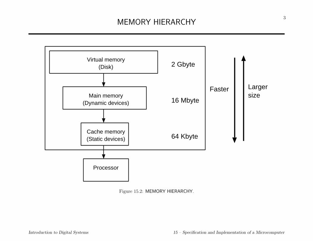
3MEMORY HIERARCHY
Virtual memory(Disk)
Main memory(Dynamic devices)
Cache memory(Static devices)
Processor
Faster Largersize
2 Gbyte
16 Mbyte
64 Kbyte
Figure 15.2: MEMORY HIERARCHY.
Introduction to Digital Systems 15 – Specification and Implementation of a Microcomputer

4
SPECIFICATION (architecture) OF A SIMPLE MICROCOMPUTER SYSTEM
Processor Memory subsystem
MemAddr
I/Osubsystem
IOAddr
MemDataIOData
MemLength
MemRd
MemWr
MemRdy
IOLength
IORd
IOWr
IORdy
Clk Reset
I/O devices
I/O Bus Memory Bus
24
1
1
1
1
32
11
1
1
1
1
32
Status
MemEnable 1IOEnable1
Figure 15.3: STRUCTURE OF XMC.
Introduction to Digital Systems 15 – Specification and Implementation of a Microcomputer
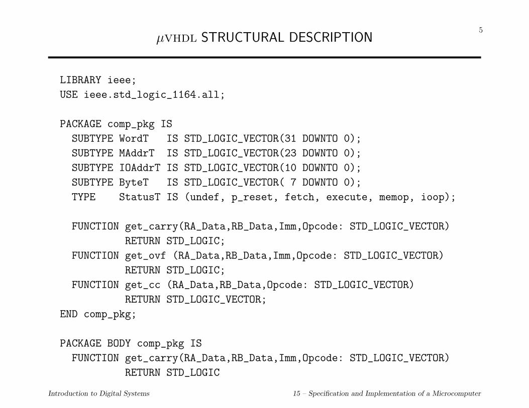
5µvhdl STRUCTURAL DESCRIPTION
LIBRARY ieee;
USE ieee.std_logic_1164.all;
PACKAGE comp_pkg IS
SUBTYPE WordT IS STD_LOGIC_VECTOR(31 DOWNTO 0);
SUBTYPE MAddrT IS STD_LOGIC_VECTOR(23 DOWNTO 0);
SUBTYPE IOAddrT IS STD_LOGIC_VECTOR(10 DOWNTO 0);
SUBTYPE ByteT IS STD_LOGIC_VECTOR( 7 DOWNTO 0);
TYPE StatusT IS (undef, p_reset, fetch, execute, memop, ioop);
FUNCTION get_carry(RA_Data,RB_Data,Imm,Opcode: STD_LOGIC_VECTOR)
RETURN STD_LOGIC;
FUNCTION get_ovf (RA_Data,RB_Data,Imm,Opcode: STD_LOGIC_VECTOR)
RETURN STD_LOGIC;
FUNCTION get_cc (RA_Data,RB_Data,Opcode: STD_LOGIC_VECTOR)
RETURN STD_LOGIC_VECTOR;
END comp_pkg;
PACKAGE BODY comp_pkg IS
FUNCTION get_carry(RA_Data,RB_Data,Imm,Opcode: STD_LOGIC_VECTOR)
RETURN STD_LOGIC
Introduction to Digital Systems 15 – Specification and Implementation of a Microcomputer
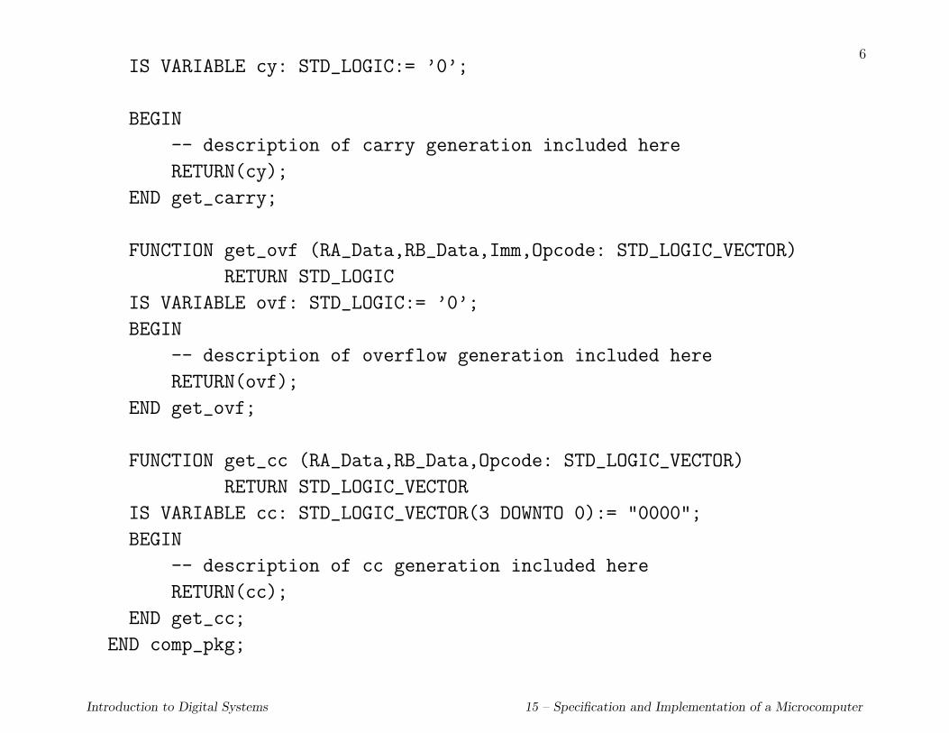
6IS VARIABLE cy: STD_LOGIC:= ’0’;
BEGIN
-- description of carry generation included here
RETURN(cy);
END get_carry;
FUNCTION get_ovf (RA_Data,RB_Data,Imm,Opcode: STD_LOGIC_VECTOR)
RETURN STD_LOGIC
IS VARIABLE ovf: STD_LOGIC:= ’0’;
BEGIN
-- description of overflow generation included here
RETURN(ovf);
END get_ovf;
FUNCTION get_cc (RA_Data,RB_Data,Opcode: STD_LOGIC_VECTOR)
RETURN STD_LOGIC_VECTOR
IS VARIABLE cc: STD_LOGIC_VECTOR(3 DOWNTO 0):= "0000";
BEGIN
-- description of cc generation included here
RETURN(cc);
END get_cc;
END comp_pkg;
Introduction to Digital Systems 15 – Specification and Implementation of a Microcomputer

7
LIBRARY ieee;
USE ieee.std_logic_1164.ALL;
USE WORK.ALL, WORK.comp_pkg.ALL;
ENTITY Computer IS
PORT (Reset, Clk : IN STD_LOGIC);
END Computer;
ARCHITECTURE structural OF Computer IS
SIGNAL MemAddr : MAddrT ; -- memory address bus
SIGNAL MemLength, MemRd : STD_LOGIC; -- memory control signals
SIGNAL MemWr, MemEnable : STD_LOGIC;
SIGNAL MemRdy : STD_LOGIC; -- memory status signal
SIGNAL MemData : WordT ; -- memory data bus
SIGNAL IOAddr : IOAddrT ; -- I/O address bus
SIGNAL IOLength, IORd : STD_LOGIC; -- I/O control signals
SIGNAL IOWr, IOEnable : STD_LOGIC;
SIGNAL IORdy : STD_LOGIC; -- I/O status signal
SIGNAL IOData : WordT ; -- I/O data bus
SIGNAL Status : StatusT;
Introduction to Digital Systems 15 – Specification and Implementation of a Microcomputer

8
BEGIN
U1: ENTITY Memory
PORT MAP (MemAddr, MemLength, MemRd, MemWr, MemEnable,
MemRdy, MemData);
U2: ENTITY IO
PORT MAP (IOAddr, IOLength, IORd, IOWr, IOEnable,
IORdy, IOData);
U3: ENTITY Processor
PORT MAP (MemAddr, MemData, MemLength, MemRd, MemWr,
MemEnable, MemRdy,
IOAddr, IOData, IOLength, IORd, IOWr,
IOEnable, IORdy,
Status, Reset, Clk);
END structural;
Introduction to Digital Systems 15 – Specification and Implementation of a Microcomputer

9MEMORY SUBSYSTEM
Addr
Length
Rd
Wr
Data
Rdy
Memory32
24
Word 0Word 4
32 bits
Byte 3 Byte 2 Byte 1 Byte 0
(b)
Word 2 -424
Byte 7 Byte 6 Byte 5 Byte 4
(a)
Enable
Addr
Rd
Wr
Data
Rdy
tmemIdle Idle
Enable
tsu tmemtsu
tmem= mem. cycle
= setup timetsu
= data validt dv
tdv
tdv
(c)
Figure 15.4: MEMORY SUBSYSTEM. (a) EXTERNAL SIGNALS. (b) INTERNAL ORGANIZATION. (c) TIMING DIAGRAM
Introduction to Digital Systems 15 – Specification and Implementation of a Microcomputer

10µvhdl ENTITY DECLARATION FOR MEMORY SUBSYSTEM
LIBRARY ieee;
USE ieee.std_logic_1164.all;
USE WORK.comp_pkg.ALL;
ENTITY Memory IS
PORT (Addr : IN MAddrT ; -- memory address bus
Length : IN STD_LOGIC; -- byte/word operand
Rd, Wr : IN STD_LOGIC; -- access control signals
Enable : IN STD_LOGIC; -- enable signal
Rdy : OUT STD_LOGIC; -- access completion signal
Data : INOUT WordT ); -- memory data bus
END Memory;
Introduction to Digital Systems 15 – Specification and Implementation of a Microcomputer

11µvhdl BEHAVIORAL DESCRIPTION OF MEMORY SUBSYSTEM
LIBRARY ieee;
USE ieee.std_logic_unsigned.ALL;
ARCHITECTURE behavioral OF Memory IS
CONSTANT Tmem : TIME := 8 ns; -- nanoseconds
CONSTANT Td : TIME := 200 ps; -- picoseconds
CONSTANT Tsu : TIME := 200 ps; -- picoseconds
BEGIN
PROCESS (Rd, Wr, Enable)
CONSTANT byte_l: STD_LOGIC:= ’0’; -- constant declarations
CONSTANT word_l: STD_LOGIC:= ’1’;
-- memory declaration
CONSTANT MaxMem : NATURAL := 16#FFFFFF#; -- 2**24 bytes
TYPE MemArrayT IS ARRAY(0 TO MaxMem-1) OF ByteT;
VARIABLE Mem : MemArrayT;
-- working variables
VARIABLE tAddr : NATURAL;
VARIABLE tData : WordT ;
VARIABLE tCtrls: STD_LOGIC_VECTOR(2 DOWNTO 0);
Introduction to Digital Systems 15 – Specification and Implementation of a Microcomputer

12
BEGIN
tCtrls:= Rd & Wr & Enable; -- group signals for simpler decoding
CASE tCtrls IS
-- output to tri-state
WHEN "000" => Data <= (OTHERS => ’Z’) AFTER Td;
WHEN "011" => -- write access;
-- indicate module busy
Rdy <= ’0’ AFTER Td, ’1’ AFTER Tmem;
IF (Length = byte_l) THEN -- read address
tAddr:= CONV_INTEGER(Addr); -- bit-vector to integer
-- from pkg std_logic_unsigned
ELSE
tAddr:= CONV_INTEGER(Addr(23 DOWNTO 2) & "00");
END IF;
CASE Length IS
WHEN byte_l => Mem(tAddr) := (Data( 7 DOWNTO 0));
WHEN word_l => Mem(tAddr) := (Data( 7 DOWNTO 0));
Mem(tAddr+1):= (Data(15 DOWNTO 8));
Mem(tAddr+2):= (Data(23 DOWNTO 16));
Mem(tAddr+3):= (Data(31 DOWNTO 24));
WHEN OTHERS => NULL;
Introduction to Digital Systems 15 – Specification and Implementation of a Microcomputer

13END CASE;
WHEN "101" => -- read access
-- indicate module busy
Rdy <= ’0’ AFTER Td, ’1’ AFTER Tmem;
IF (Length = byte_l) THEN -- read address
tAddr:= CONV_INTEGER(Addr); -- bit-vector to integer
ELSE
tAddr:= CONV_INTEGER(Addr(23 DOWNTO 2) & "00");
END IF;
CASE Length IS
WHEN byte_l => tData( 7 DOWNTO 0):= (Mem(tAddr));
WHEN word_l => tData( 7 DOWNTO 0):= (Mem(tAddr));
tData(15 DOWNTO 8):= (Mem(tAddr+1));
tData(23 DOWNTO 16):= (Mem(tAddr+2));
tData(31 DOWNTO 24):= (Mem(tAddr+3));
WHEN OTHERS => NULL;
END CASE;
Data <= tData AFTER Tmem; -- deliver data
WHEN OTHERS => NULL; -- memory not enabled
END CASE;
END PROCESS;
Introduction to Digital Systems 15 – Specification and Implementation of a Microcomputer

14
-- timing verifications
ASSERT NOT (Rd’EVENT AND Rd=’1’ AND NOT Addr’STABLE(Tsu))
REPORT "Read address setup time violation";
ASSERT NOT (Rd’EVENT AND Rd=’1’ AND NOT Enable’STABLE(Tsu))
REPORT "Read enable setup time violation";
ASSERT NOT (Wr’EVENT AND Wr=’1’ AND NOT Addr’STABLE(Tsu))
REPORT "Write address setup time violation";
ASSERT NOT (Wr’EVENT AND Wr=’1’ AND NOT Enable’STABLE(Tsu))
REPORT "Write enable setup time violation";
END behavioral;
Introduction to Digital Systems 15 – Specification and Implementation of a Microcomputer

15
INPUT/OUTPUT (I/O) SUBSYSTEM
I/O Port 0I/O Port 1
I/O Port 2047
32 bits
Addr
Length
Rd
Wr
Data
Rdy
I/Osubsystem
(a) (b)
32
11
Enable
Figure 15.5: INPUT/OUTPUT SUBSYSTEM.
Introduction to Digital Systems 15 – Specification and Implementation of a Microcomputer
16
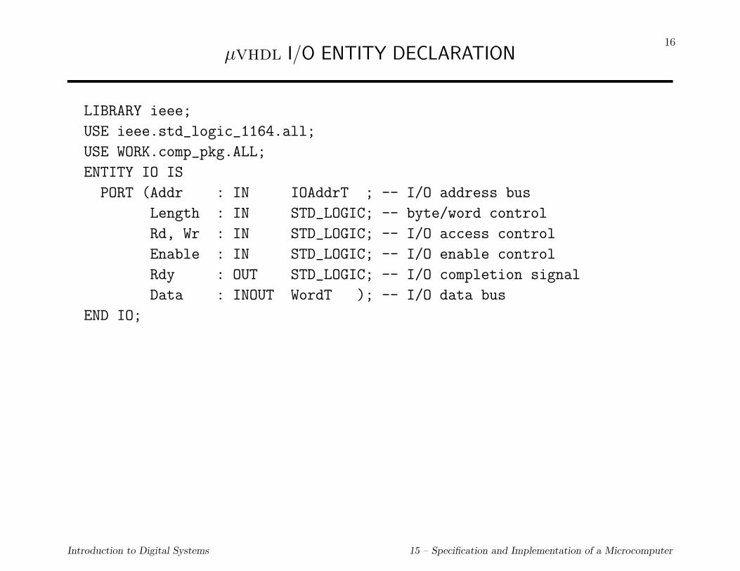
µvhdl I/O ENTITY DECLARATION
LIBRARY ieee;
USE ieee.std_logic_1164.all;
USE WORK.comp_pkg.ALL;
ENTITY IO IS
PORT (Addr : IN IOAddrT ; -- I/O address bus
Length : IN STD_LOGIC; -- byte/word control
Rd, Wr : IN STD_LOGIC; -- I/O access control
Enable : IN STD_LOGIC; -- I/O enable control
Rdy : OUT STD_LOGIC; -- I/O completion signal
Data : INOUT WordT ); -- I/O data bus
END IO;
Introduction to Digital Systems 15 – Specification and Implementation of a Microcomputer

17PROCESSOR
Processor state
• 32 general-purpose registers (32-bits wide), called R0, R1, ..., R31;
• a 24-bit Program Counter register (PC);
• a 4-bit Condition Register (CR); and
• a 32-bit Instruction Register (IR).
Memory Bus I/O Bus
CR Z N C V
PC
IR
General Purpose Registers
R0R1R2
R31
Figure 15.6: PROCESSOR STATE.
Introduction to Digital Systems 15 – Specification and Implementation of a Microcomputer

18BEHAVIOR OF PROCESSOR
Fetch instruction
Execute instruction andcompute address of next instr.
(a)
MemAddr
Clk
DataBus
MemRdy
MemRd
Fetch ExecuteMemoryaccess
Inst. Data
Inst. Addr. Data Addr.
Execute(Addr. calc.)
Fetch
(i) (ii)
Inst.
Inst. Addr.
MemEnable
Figure 15.7: BEHAVIOR OF THE PROCESSOR. (a) INSTRUCTION LOOP. (b) MEMORY BUS BEHAVIOR FOR REGISTEROPERATION. (c) MEMORY BUS BEHAVIOR FOR LOAD OPERATION.
Introduction to Digital Systems 15 – Specification and Implementation of a Microcomputer

19BEHAVIOR OF INSTRUCTIONS
R1
R5
R7
CR
conds.
Memory
IR= branch 2000
addr.gen.
(a) (b)
Memory
IR= add R7,R1,R5
PC
+4
branch 2000add R7,R1,R5
PC
Memory
IR= branch cond,2000
addr.gen.
(c)
branch cond,2000
PC
cond?
+4
selector
Figure 15.8: BEHAVIOR OF INSTRUCTIONS. (a) ADD instruction. (b) UNCONDITIONAL BRANCH INSTRUCTION. (c) CON-DITIONAL BRANCH INSTRUCTION.
Introduction to Digital Systems 15 – Specification and Implementation of a Microcomputer

20INSTRUCTION SEQUENCING
• SEQUENTIAL UNLESS
1. UNCONDITIONAL BRANCH
2. CONDITIONAL BRANCH
Introduction to Digital Systems 15 – Specification and Implementation of a Microcomputer

21
31 25 20 15 10 0
RT:= op(RA) Opcode RT RA --
RT:= RA op RB Opcode RT RA RB --
RT:= RA op SI Opcode RT RA SI
RT:= RA op UI Opcode RT RA UI
RT:= M[RA+D] Opcode RT RA D
M[RA+D]:= RS Opcode RS RA D
RT:= IO[PN] Opcode RT RA -- PN
IO[PN]:= RS Opcode RS RA -- PN
PC:= PC + 4 + D Opcode -- D
PC:= RA Opcode -- RA --
Figure 15.9: INSTRUCTION FORMATS.
Introduction to Digital Systems 15 – Specification and Implementation of a Microcomputer

22
Table 15.2: INSTRUCTION SET
Name Opcode Function CR Assembly Language
No-op 000000 no operation nop
not 000010 RT:= not(RA) Y not RT,RALeft shift 000100 RT:= lshift(RA) Y lsh RT,RARight shift 000110 RT:= rshift(RA) Y rsh RT,RALeft rotate 001000 RT:= lrot(RA) Y lrt RT,RARight rot. 001010 RT:= rrot(RA) Y rrt RT,RA
Add 010000 RT:= RA + RB Y add RT,RA,RBAdd immed. 010001 RT:= RA + SI Y adi RT,RA,SISubtract 010010 RT:= RA - RB Y sub RT,RA,RBSub. immed. 010011 RT:= RA - SI Y sbi RT,RA,SIand 010100 RT:= RA and RB Y and RT,RA,RBand immed. 010101 RT:= RA and UI Y ani RT,RA,UIor 010110 RT:= RA or RB Y or RT,RA,RBor immed. 010111 RT:= RA or UI Y ori RT,RA,UIxor 011000 RT:= RA xor RB Y xor RT,RA,RBxor immed. 011001 RT:= RA xor UI Y xri RT,RA,UI
Introduction to Digital Systems 15 – Specification and Implementation of a Microcomputer

23
Table 15.3: INSTRUCTION SET (cont.)
Name Opcode Function CR Assembly Language
Load byte 100000 RT( 7 to 0):= Mem(RA+D,1) ldb RT,D(RA)Load word 100001 RT(31 to 0):= Mem(RA+D,4) ldw RT,D(RA)Store byte 100010 Mem(RA+D,1):= RS( 7 to 0) stb RS,D(RA)Store word 100011 Mem(RA+D,4):= RS(31 to 0) stw RS,D(RA)I/O Rd byte 100100 RT( 7 to 0):= IO(PN,1) irb RT,PNI/O Rd word 100101 RT(31 to 0):= IO(PN,4) irw RT,PNI/O Wr byte 100110 IO(PN,1):= RS( 7 to 0) iwb RS,PNI/O Wr word 100111 IO(PN,4):= RS(31 to 0) iww RS,PN
Introduction to Digital Systems 15 – Specification and Implementation of a Microcomputer

24
Table 15.4: INSTRUCTION SET (cont.)
Name Opcode Function CR Assembly Language
Branch 111000 PC:= PC + 4 + D br DBranch indirect 111001 PC:= RA bri RABranch if N=0 110000 If N=0 then PC:= PC+4+D brp DBranch if N=1 110001 If N=1 then PC:= PC+4+D brn DBranch if Z=0 110010 If Z=0 then PC:= PC+4+D bnz DBranch if Z=1 110011 If Z=1 then PC:= PC+4+D brz DBranch if C=0 110100 If C=0 then PC:= PC+4+D bnc DBranch if C=1 110101 If C=1 then PC:= PC+4+D brc DBranch if V=0 110110 If V=0 then PC:= PC+4+D bnv DBranch if V=1 110111 If V=1 then PC:= PC+4+D brv D
Introduction to Digital Systems 15 – Specification and Implementation of a Microcomputer

25µvhdl SPECIFICATION OF PROCESSOR
LIBRARY ieee;
USE ieee.std_logic_1164.all;
USE WORK.comp_pkg.ALL;
ENTITY processor IS
PORT (MemAddr : OUT MAddrT ; -- memory address bus
MemData : INOUT WordT ; -- data bus to/from memory
MemLength: OUT STD_LOGIC; -- memory operand length
MemRd : OUT STD_LOGIC; -- memory read control signal
MemWr : OUT STD_LOGIC; -- memory write control signal
MemEnable: OUT STD_LOGIC; -- memory enable signal
MemRdy : IN STD_LOGIC; -- memory completion signal
IOAddr : OUT IOAddrT ; -- I/O address bus
IOData : INOUT WordT ; -- data bus to/from I/O
IOLength : OUT STD_LOGIC; -- I/O operand length
IORd : OUT STD_LOGIC; -- I/O read control signal
IOWr : OUT STD_LOGIC; -- I/O write control signal
IOEnable : OUT STD_LOGIC; -- memory enable signal
IORdy : IN STD_LOGIC; -- I/O completion signal
Status : OUT StatusT ; -- processor status signal
Reset : IN STD_LOGIC; -- reset signal
Clk : IN STD_LOGIC); -- clock signal
END processor;
Introduction to Digital Systems 15 – Specification and Implementation of a Microcomputer

26µvhdl SPECIFICATION OF BEHAVIOR
LIBRARY ieee;
USE ieee.std_logic_arith.all; -- use definitions and operations
USE ieee.std_logic_signed.all; -- on signed values
ARCHITECTURE behavioral OF processor IS
-- registers (processor state)
TYPE RegFileT IS ARRAY(0 to 31) OF WordT;
SIGNAL GPR: RegFileT ; -- general registers
SIGNAL PC : MAddrT ; -- Program Counter register
SIGNAL CR : STD_LOGIC_VECTOR( 3 DOWNTO 0); -- Condition Register
SIGNAL IR : STD_LOGIC_VECTOR(31 DOWNTO 0); -- Instruction register
-- signals used by output function
SIGNAL Phase: StatusT ; -- instr. cycle phase
SIGNAL tMemAddr: WordT ; -- memory address
SIGNAL tData : WordT ; -- memory/io data
ALIAS Z : STD_LOGIC IS CR(0) ; -- Condition code Zero
ALIAS N : STD_LOGIC IS CR(1) ; -- Condition code Negative
ALIAS C : STD_LOGIC IS CR(2) ; -- Condition code Carry
ALIAS O : STD_LOGIC IS CR(3) ; -- Condition code Overflow
Introduction to Digital Systems 15 – Specification and Implementation of a Microcomputer

27
ALIAS Opcode : STD_LOGIC_VECTOR(5 DOWNTO 0) IS IR(31 DOWNTO 26);
ALIAS RT : STD_LOGIC_VECTOR(4 DOWNTO 0) IS IR(25 DOWNTO 21);
ALIAS RA : STD_LOGIC_VECTOR(4 DOWNTO 0) IS IR(20 DOWNTO 16);
ALIAS RB : STD_LOGIC_VECTOR(4 DOWNTO 0) IS IR(15 DOWNTO 11);
ALIAS RS : STD_LOGIC_VECTOR(4 DOWNTO 0) IS IR(15 DOWNTO 11);
ALIAS Imm : STD_LOGIC_VECTOR(15 DOWNTO 0) IS IR(15 DOWNTO 0);
ALIAS D : STD_LOGIC_VECTOR(15 DOWNTO 0) IS IR(15 DOWNTO 0);
ALIAS PN : STD_LOGIC_VECTOR(10 DOWNTO 0) IS IR(10 DOWNTO 0);
ALIAS dlength: STD_LOGIC IS IR(26) ;
-- other declarations
CONSTANT delay : TIME := 200 ps; -- register delay
CONSTANT Reset_delay: TIME := 5 ns;
CONSTANT Exec_delay : TIME := 10 ns; -- Execute delay
CONSTANT Mdelay : TIME := 600 ps; -- MemEnable signal delay
CONSTANT Pulse_Width: TIME := 2.6 ns; -- memory signals width
CONSTANT Fetch_delay: TIME := 3 ns; -- disable memory after
-- access completed
Introduction to Digital Systems 15 – Specification and Implementation of a Microcomputer
28
BEGIN
PROCESS -- transition function
-- working variables
VARIABLE RS_data, RA_data, RB_data : WordT;
VARIABLE RT_addr, RA_addr, RB_addr, RS_addr : Natural;
BEGIN
WAIT ON Clk,Reset;
IF (Reset’Event AND Reset = ’1’) THEN -- reset function
PC <= (OTHERS => ’0’); CR <= "0000"; IR <= (OTHERS => ’0’);
FOR i IN 0 TO 31 LOOP
GPR(i) <= (OTHERS => ’0’);
END LOOP;
Phase <= p_reset;
Status <= p_reset;
WAIT UNTIL (Reset = ’0’) AND (Clk = ’1’);
END IF;
Introduction to Digital Systems 15 – Specification and Implementation of a Microcomputer

29
IF (Clk’Event AND Clk=’1’) THEN
-- Instruction cycle
Status <= Fetch AFTER delay;
Phase <= Fetch AFTER delay;
-- instruction fetch
PC <= PC + 4 AFTER Exec_delay;
WAIT UNTIL MemRdy=’1’; -- wait instr. fetch completed
IR <= MemData;
WAIT FOR Fetch_delay;
-- instruction execution
Status <= Execute;
Phase <= Execute;
RA_addr := CONV_INTEGER(’0’ & RA); RB_addr := CONV_INTEGER(’0’ & RB);
-- ’0’ to force bit-vector to positive value
RA_data := GPR(RA_addr) ; RB_data := GPR(RB_addr) ;
RT_addr := CONV_INTEGER(’0’ & RT);
RS_addr := CONV_INTEGER(’0’ & RS); -- source reg. for store
RS_data := GPR(RS_addr) ; -- or I/O write
WAIT FOR Exec_delay;
Introduction to Digital Systems 15 – Specification and Implementation of a Microcomputer

30
CASE Opcode IS
WHEN "000000" => null; -- nop
WHEN "000010" => GPR(RT_Addr)<= not(RA_data); -- not
WHEN "000100" => GPR(RT_Addr)<= RA_data(30 DOWNTO 0) & ’0’; -- lshift
WHEN "000110" => GPR(RT_Addr)<= ’0’ & RA_data(31 DOWNTO 1); -- rshift
-- lrotate
WHEN "001000" => GPR(RT_Addr)<= RA_data(30 DOWNTO 0) & RA_data(31);
-- rrotate
WHEN "001010" => GPR(RT_Addr)<= RA_DATA(0) & RA_data(31 DOWNTO 1);
WHEN "010000" => GPR(RT_Addr)<= RA_data + RB_data ; -- add
WHEN "010001" => GPR(RT_Addr)<= RA_data + Imm;
WHEN "010010" => GPR(RT_Addr)<= RA_data - RB_data ; -- sub
WHEN "010011" => GPR(RT_Addr)<= RA_data - Imm;
WHEN "010100" => GPR(RT_Addr)<= RA_data and RB_data ; -- and
WHEN "010101" => GPR(RT_Addr)<= RA_data and ext(Imm,RA_data’LENGTH);
-- ext: zero extension from ieee pkg
WHEN "010110" => GPR(RT_Addr)<= RA_data or RB_data ; -- or
WHEN "010111" => GPR(RT_Addr)<= RA_data or ext(Imm,RA_data’LENGTH);
Introduction to Digital Systems 15 – Specification and Implementation of a Microcomputer
31WHEN "011000" => GPR(RT_Addr)<= RA_data xor RB_data ; -- xor
WHEN "011001" => GPR(RT_Addr)<= RA_data xor ext(Imm,RA_data’LENGTH);
WHEN "100000" | "100001" => -- ldb, ldw
Phase <= MemOp;
Status <= MemOp;
tMemAddr <= RA_data + D; -- mem.addr.
WAIT until MemRdy = ’1’;
WHEN "100010" | "100011" => -- stb, stw
Phase <= MemOp;
Status <= MemOp;
tMemAddr <= RA_data + D; -- mem. addr.
tData <= RS_data; -- mem. data
WAIT until MemRdy = ’1’;
WHEN "100100" | "100101" => -- irb, irw
Phase <= IOOp;
Status <= IOOp;
WAIT until IORdy = ’1’ ;
Introduction to Digital Systems 15 – Specification and Implementation of a Microcomputer

32WHEN "100110" | "100111" => -- iwb, iww
Phase <= IOOp;
Status <= IOOp;
tData <= RS_data; -- io data
WAIT until IORdy = ’1’ ;
WHEN "111000" => PC <= PC + D; -- branch
WHEN "111001" => PC <= RA_data(23 DOWNTO 0); -- br.ind.
WHEN "110000" | "110001"
=> IF (N = Opcode(0)) THEN -- br on N
PC <= PC + D;
END IF;
WHEN "110010" | "110011"
=> IF (Z = Opcode(0)) THEN -- br on Z
PC <= PC + D;
END IF;
WHEN "110100" | "110101"
=> IF (C = Opcode(0)) THEN -- br on C
PC <= PC + D;
END IF;
WHEN "110110" | "110111"
=> IF (O = Opcode(0)) THEN -- br on V
PC <= PC + D;
Introduction to Digital Systems 15 – Specification and Implementation of a Microcomputer

33END IF;
WHEN others => null;
END CASE;
IF ((Opcode(5 DOWNTO 4) = 0) or (Opcode(5 DOWNTO 4) = 1))
and (Opcode /= 0) THEN
-- set condition register
IF (GPR(RT_Addr) = 0) THEN CR(0) <= ’1’; -- zero result
ELSE CR(0) <= ’0’;
END IF;
IF (GPR(RT_Addr)(31) = ’1’) THEN CR(1) <= ’1’; -- negative result
ELSE CR(1) <= ’0’;
END IF;
-- check if operation Opcode generates carry out
CR(2) <= get_carry(RA_Data,RB_Data,Imm,Opcode);
-- check if operation Opcode generates overflow
CR(3) <= get_ovf(RA_Data,RB_Data,Imm,Opcode);
END IF;
WAIT FOR 0 ns; -- force signals to be updated
Introduction to Digital Systems 15 – Specification and Implementation of a Microcomputer

34IF (Phase = MemOp) THEN
IF (dlength = ’1’) THEN -- ldw
GPR(RT_addr) <= MemData;
ELSE -- ldb
GPR(RT_addr)( 7 DOWNTO 0) <= MemData(7 DOWNTO 0);
GPR(RT_addr)(31 DOWNTO 8) <= (OTHERS => ’0’);
END IF;
WAIT FOR Fetch_delay;
END IF;
IF (Phase = IOOp) THEN
IF (dlength = ’1’) THEN -- irw
GPR(RT_addr) <= IOData;
ELSE -- irb
GPR(RT_addr)( 7 DOWNTO 0) <= IOData(7 DOWNTO 0);
GPR(RT_addr)(31 DOWNTO 8) <= (OTHERS => ’0’);
END IF;
WAIT FOR Fetch_delay;
END IF;
END IF;
END PROCESS;
PROCESS -- output function
Introduction to Digital Systems 15 – Specification and Implementation of a Microcomputer

35BEGIN
-- Instruction cycle
WAIT ON Phase;
IF (Phase = p_reset) THEN -- reset
MemRd <= ’0’; MemWr <= ’0’; MemEnable <= ’0’; MemLength <= ’0’;
MemData <= (OTHERS => ’Z’);
IORd <= ’0’; IOWr <= ’0’; IOEnable <= ’0’; IOLength <= ’0’;
IOData <= (OTHERS => ’Z’);
ELSIF (Phase = Fetch) THEN -- instruction fetch
MemAddr <= PC AFTER delay;
MemEnable <= ’1’ AFTER delay;
MemRd <= ’1’ AFTER Mdelay, ’0’ AFTER Pulse_Width;
MemLength <= ’1’ AFTER delay;
WAIT UNTIL MemRdy=’1’; -- wait instr. fetch completed
MemEnable <= ’0’ AFTER Fetch_delay;
ELSIF (Phase = Execute) THEN NULL; -- instruction execution
-- no output signals
ELSIF (Phase = MemOp) THEN
MemAddr <= tMemAddr(23 DOWNTO 0) AFTER delay;
MemEnable <= ’1’ AFTER delay;
Introduction to Digital Systems 15 – Specification and Implementation of a Microcomputer

36MemLength <= dlength AFTER delay;
IF ((To_Bitvector(Opcode) = "100000") OR
(To_Bitvector(Opcode) = "100001")) THEN -- ldb, ldw
MemRd <= ’1’ AFTER Mdelay, ’0’ AFTER Pulse_Width;
WAIT until MemRdy = ’1’;
MemEnable <= ’0’ AFTER Fetch_delay;
WAIT FOR Fetch_delay;
END IF;
IF ((To_Bitvector(Opcode) = "100010") OR
(To_Bitvector(Opcode) = "100011")) THEN -- stb, stw
MemWr <= ’1’ AFTER Mdelay, ’0’ AFTER Pulse_Width;
IF (dlength = ’1’) THEN -- stw
MemData <= tData AFTER delay;
ELSE -- stb
MemData(7 DOWNTO 0) <= tData(7 DOWNTO 0) AFTER delay;
END IF;
WAIT until MemRdy = ’1’;
MemEnable <= ’0’ AFTER delay;
MemData <= (OTHERS => ’Z’) AFTER delay;
WAIT FOR delay;
END IF;
ELSIF (Phase = IOOp) THEN
Introduction to Digital Systems 15 – Specification and Implementation of a Microcomputer

37IOAddr <= PN AFTER delay;
IOEnable <= ’1’ AFTER delay;
IOLength <= dlength AFTER delay;
IF ((To_Bitvector(Opcode) = "100100") OR
(To_Bitvector(Opcode) = "100101")) THEN -- irb, irw
IORd <= ’1’ AFTER Mdelay, ’0’ AFTER Pulse_Width;
WAIT until IORdy = ’1’ ;
IOEnable <= ’0’ AFTER Fetch_delay;
WAIT FOR Fetch_delay;
END IF;
IF ((To_Bitvector(Opcode) = "100110") OR
(To_Bitvector(Opcode) = "100111")) THEN -- iwb, iww
IF (dlength = ’1’) THEN -- iww
IOData <= tData AFTER delay;
ELSE -- iwb
IOData(7 DOWNTO 0) <= tData(7 DOWNTO 0) AFTER delay;
END IF;
IOWr <= ’1’ AFTER Mdelay, ’0’ AFTER Pulse_Width;
WAIT until IORdy = ’1’;
IOEnable <= ’0’ AFTER delay;
IOData <= (OTHERS => ’Z’) AFTER delay;
WAIT FOR delay;
END IF;
Introduction to Digital Systems 15 – Specification and Implementation of a Microcomputer

38END IF;
END PROCESS;
END behavioral;
Introduction to Digital Systems 15 – Specification and Implementation of a Microcomputer

39µvhdl SPECIFICATION OF MEMORY CONTENTS
-- memory declaration
CONSTANT MaxMem: NATURAL:= 16#FFF#; -- 4Kbytes
TYPE MemArrayT IS ARRAY(0 to MaxMem-1) OF ByteT;
VARIABLE Mem : MemArrayT:=
(-- program
3=>"01100000", 2=>"00000000", 1=>"00000000", 0=>"00000000",
7=>"01000100", 6=>"00100000", 5=>"00000000", 4=>"00110010",
11=>"10000110", 10=>"10000001", 9=>"00000000", 8=>"00000000",
15=>"10000110", 14=>"10100001", 13=>"00000000", 12=>"00000100",
19=>"01000100", 18=>"01000000", 17=>"00000000", 16=>"00111111",
23=>"10001000", 22=>"01000001", 21=>"00000000", 20=>"00000000",
-- data
51=>"00110011", 50=>"00001111", 49=>"11110000", 48=>"11001100",
55=>"00110011", 54=>"00001111", 53=>"11110000", 52=>"11001100",
OTHERS => "00000000");
where the memory contents corresponds to the following instructions:0x000000: xor R0,R0,R0 ; R0 = 0
0x000004: adi R1,R0,50 ; R1 = 50
0x000008: ldw R20,0(R1) ; R20= Mem(50,4)= Mem(48,4)
0x00000C: ldw R21,4(R1) ; R21= Mem(54,4)= Mem(52,4)
0x000010: adi R2,R0,63 ; R2 = 63
0x000014: stb R2,0(R1) ; Mem(50,1) = 63
0x000048: 0x330FF0CC
0x000052: 0x330FF0CC
Introduction to Digital Systems 15 – Specification and Implementation of a Microcomputer

40IMPLEMENTATION OF XMC
• MEMORY SUBSYSTEM
• PROCESSOR
1. DATA SUBSYSTEM
2. CONTROL SUBSYSTEM
Introduction to Digital Systems 15 – Specification and Implementation of a Microcomputer

41MEMORY SUBSYSTEM
Byte 3 Byte 2 Byte 1 Byte 0
Address
2
Length Selector/Distributor
32
Data
8 8 8 8
Rd
Wr MRdyController
22
Controls
2 x1 bits22
Enable
Figure 15.10: IMPLEMENTATION OF THE MEMORY SUBSYSTEM.
Introduction to Digital Systems 15 – Specification and Implementation of a Microcomputer

42PROCESSOR
Datasubsystem
Controlsubsystem
InstrZE,NG,CY,OV
MemRdMemWr
MemAddr
ClkReset
MemData
IOData
IOAddr
MemEnableIORd
MemRdy
IOWr
MemLength
IORdy
4
32
24
32
11
32
Condition signals
Control signals
Datasignals
Status
IOLengthIOEnable
Figure 15.11: IMPLEMENTATION OF THE PROCESSOR.
Introduction to Digital Systems 15 – Specification and Implementation of a Microcomputer

43DATA SUBSYSTEM
Registerfile
IR
PC
Z N C V
WrCRALU
DataA
DataB
WrPC
ALUOp
Mux4
MemAddr
MemData
ALU_PC
WrIR
IR_RB
Instr
ZE,NG,CY,OV
ALUdataCond
Sw
itch
Mux1
Mem_ALU
Reset
AddrC
MemData
Mux3
Reset
Reset
AddrA
AddrB
Reset
WrC
DataC
01
01
01
PCout
PCin
Bin
Sin_Sout
Ain
0
1
SE_ZEExt
ndr.
Mux210
PC_RA
BA
C
B
AC
Clk
Clk
Clk
Clk
Figure 15.12: IMPLEMENTATION OF DATA SUBSYSTEM (I/O signals not shown).
Introduction to Digital Systems 15 – Specification and Implementation of a Microcomputer

44ALU
ALUop Operation0000 Zero 320001 A + B0010 A - B0011 -B0100 A and B0101 A or B0110 A xor B0111 not(B)1000 unused1001 B1010 shiftl(A)1011 shiftr(A)1100 rotl(A)1101 rotr(A)1110 A + 41111 unused
Introduction to Digital Systems 15 – Specification and Implementation of a Microcomputer

45EVENT SEQUENCE FOR ALU INSTRUCTION
Registerfile
IR
PC
Z N C V
MemAddr
MemData
ALU_PC
Instr
ZE,NG,CY,OV
1AddrA
AddrB
3
ALUOpCond
AddrCWrC
3
2
WrCR
IR_RB
Mem_ALU
PC_RA22
2
2
2
2
2
2
4
4
DataA
DataB
Clk
Clk
DataC
Mux1
Mux3Mux2
2
2
Figure 15.13: SEQUENCE OF EVENTS IN DATA SUBSYSTEM FOR ALU INSTRUCTION.
Introduction to Digital Systems 15 – Specification and Implementation of a Microcomputer

46TIMING DIAGRAM FOR ALU INSTRUCTION
Instr
Clk
AddrA
instructiondecode
registerread delay
Add Instruction
AddrB
DataA
DataB
ALUop
DataC
Cond
AddrC
WrC
ALUopdelay
registersetup
WrCR
3 421
Figure 15.14: TIMING DIAGRAM FOR ALU INSTRUCTION IN DATA SUBSYSTEM.
Introduction to Digital Systems 15 – Specification and Implementation of a Microcomputer
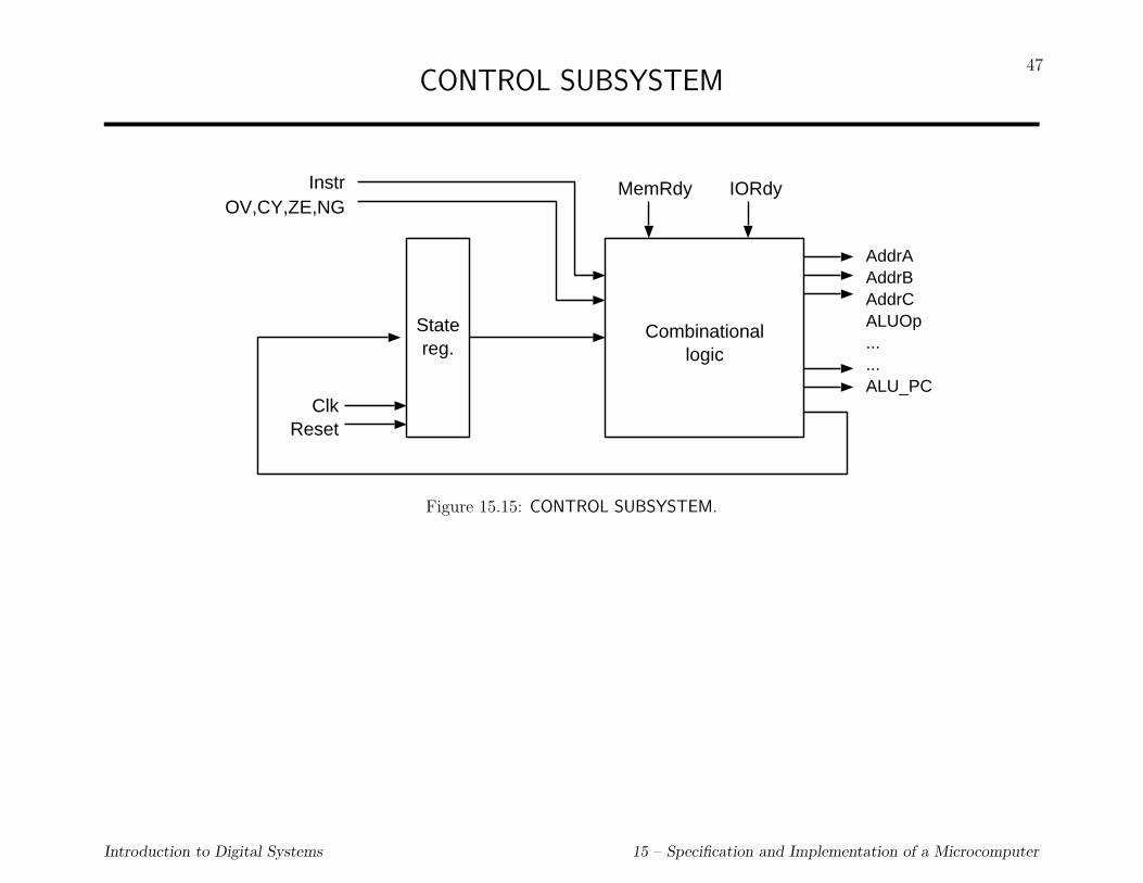
47CONTROL SUBSYSTEM
InstrOV,CY,ZE,NG
ClkReset
Statereg.
Combinationallogic
AddrAAddrBAddrCALUOp......ALU_PC
MemRdy IORdy
Figure 15.15: CONTROL SUBSYSTEM.
Introduction to Digital Systems 15 – Specification and Implementation of a Microcomputer
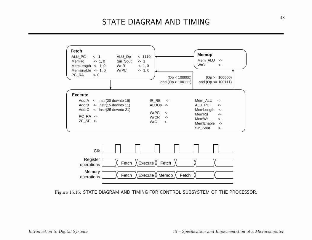
48STATE DIAGRAM AND TIMING
Fetch
Execute
Memop
Fetch Execute Fetch
Fetch Execute Memop Fetch
Clk
Register operations
Memoryoperations
ALU_PC <- 1MemRd <- 1, 0MemLength <- 1, 0MemEnable <- 1, 0PC_RA <- 0
AddrA <- Instr(20 downto 16)AddrB <- Instr(15 downto 11)AddrC <- Instr(25 downto 21)
ALU_Op <- 1110Sin_Sout <- 1WrIR <- 1, 0WrPC <- 1, 0
PC_RA <- ZE_SE <-
IR_RB <- ALUOp <-
WrPC <- WrCR <- WrC <-
Mem_ALU <- ALU_PC <-MemLength <- MemRd <- MemWr <-MemEnable <-Sin_Sout <-
Mem_ALU <- WrC <-
(Op < 100000)and (Op > 100111)
(Op >= 100000)and (Op <= 100111)
Figure 15.16: STATE DIAGRAM AND TIMING FOR CONTROL SUBSYSTEM OF THE PROCESSOR.
Introduction to Digital Systems 15 – Specification and Implementation of a Microcomputer
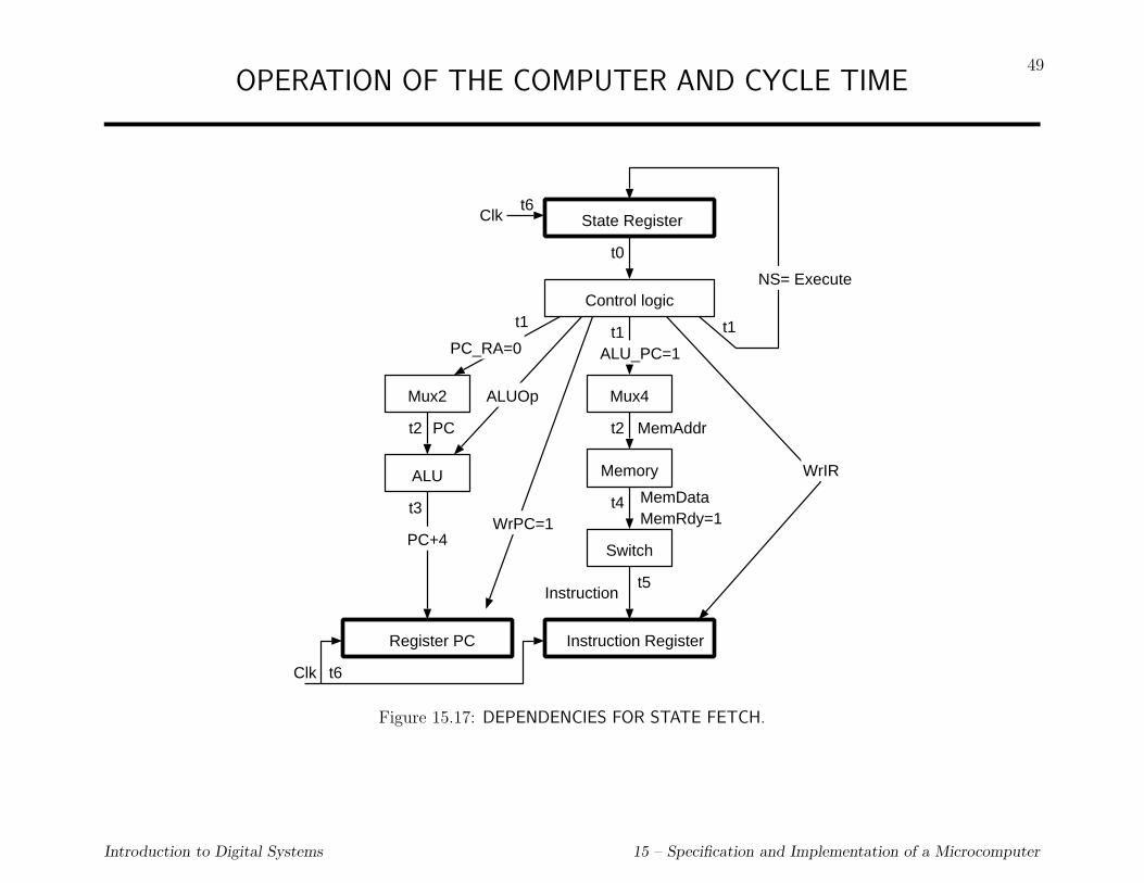
49OPERATION OF THE COMPUTER AND CYCLE TIME
State Register
t0
Control logic
t1t1t1
Mux4
t2
t4
Switch
Instruction Register
NS= Execute
ALU_PC=1
MemAddr
MemDataMemRdy=1
Instruction
Mux2
t2
ALU
Register PC
t6
PC+4
PC_RA=0
ALUOp
WrPC=1
WrIR
PC
Clk
t6Clk
Memory
t3
t5
Figure 15.17: DEPENDENCIES FOR STATE FETCH.
Introduction to Digital Systems 15 – Specification and Implementation of a Microcomputer

50STATE EXECUTE
State Register
t7
Control logic
t8
NS= Fetch or Memop t18Clk
Decode logic
AddrA, AddrB, AddrC
Reg. File
t10DataA
t9
Instr. specific control signals
Zero/Sign Extender
t11
Mux3 Mux2
ALU
t12
t14ALUData
PC
Mux1
DataC t15
IRt7
t10DataB
t13
Reg. File (t16)t17Clk
t9
t9 t9
t9
t9
t7
Figure 15.18: DEPENDENCIES FOR STATE EXECUTE.
Introduction to Digital Systems 15 – Specification and Implementation of a Microcomputer

51STATE MEMOP
Clk
State Register
t19
Control logicNS= Fetch
t25Clk
WrC=1
MemRdy
Reg. File (t24)
t23 DataC
t18
Memory
t21
Switch
t22
Mux1
t25
t15 t20
t19
Figure 15.19: DEPENDENCIES FOR STATE Memop.
Introduction to Digital Systems 15 – Specification and Implementation of a Microcomputer

52EXAMPLE 15.1: OBTAIN MIN CYCLE PERIOD
Register Reg delay tR 2 ns (setup and propagation delay)
Register file RF delay tRF 4 ns
ALU ALU delay tALU 6 ns
Multiplexer Mux delay tmux 0.5 ns
Zero/sign ext. Ext delay tZSE 0.5 ns
Switch Switch delay tsw 0.5 ns
Control delay Ctrl delay tctl 0.5 ns
Decode delay Dec delay tdec 3 ns
Memory Mem delay tmem 8 ns (static memory)
CRITICAL PATHS ARE OBTAINED:
tfetch = tR + tctl + tmux + tmem + tsw
= 2 + 0.5 + 1 + 8 + 0.5 = 12ns
texec = tR + tctl + tRF + tmux + tALU + tmux + tRF
= 2 + 0.5 + 4 + 0.5 + 6 + 0.5 + 4 = 17.5ns
tmemop = tR + tctl + tmem + tsw + tmux + tRF
= 2 + 0.5 + 8 + 0.5 + 0.5 + 4 = 15ns
Introduction to Digital Systems 15 – Specification and Implementation of a Microcomputer

53µvhdl DESCRIPTION OF IMPLEMENTATION
LIBRARY ieee; USE ieee.std_logic_1164.ALL; USE WORK.comp_pkg.ALL, WORK.ALL;
ARCHITECTURE structural OF Processor IS
SIGNAL Instr : WordT;
SIGNAL ZE, NG, CY, OV : STD_LOGIC;
SIGNAL AddrA, AddrB, AddrC : STD_LOGIC_VECTOR(4 DOWNTO 0);
SIGNAL ALUOp : STD_LOGIC_VECTOR(3 DOWNTO 0);
SIGNAL WrC, WrPC, WrCR, WrIR : STD_LOGIC;
SIGNAL Mem_ALU, PC_RA, IR_RB : STD_LOGIC;
SIGNAL ALU_PC, ZE_SE, SinSout: STD_LOGIC;
BEGIN
P1: ENTITY Data_Subsystem
PORT MAP (MemAddr, MemData, IOAddr, IOData,
Instr, ZE, NG, CY, OV, AddrA, AddrB, AddrC, ALUOp,
WrC, WrPC, WrCR, WrIR, Mem_ALU, PC_RA, IR_RB, ALU_PC,
ZE_SE, SinSout, Clk, Reset);
P2: ENTITY Ctrl_Subsystem
PORT MAP (Instr, ZE, NG, CY, OV, AddrA, AddrB, AddrC, ALUOp,
WrC, WrPC, WrCR, WrIR, Mem_ALU, PC_RA, IR_RB, ALU_PC,
ZE_SE, SinSout, MemRd, MemWr, MemLength, MemEnable,
MemRdy, IORd, IOWr, IOLength, IOEnable, IORdy, Status,
Clk, Reset);
END structural;
Introduction to Digital Systems 15 – Specification and Implementation of a Microcomputer

54µvhdl DESCRIPTION OF DATA SUBSYSTEM
LIBRARY ieee;
USE ieee.std_logic_1164.ALL;
USE WORK.comp_pkg.ALL, WORK.ALL;
ENTITY Data_Subsystem IS
PORT(MemAddr : OUT MAddrT ;
MemData : INOUT WordT ;
IOAddr : OUT IOAddrT ;
IOData : INOUT WordT ;
Instr : OUT WordT ;
ZE, NG, CY, OV : OUT STD_LOGIC ;
AddrA, AddrB, AddrC : IN STD_LOGIC_VECTOR(4 DOWNTO 0);
ALUOp : IN STD_LOGIC_VECTOR(3 DOWNTO 0);
WrC, WrPC, WrCR, WrIR : IN STD_LOGIC ;
Mem_ALU, PC_RA, IR_RB : IN STD_LOGIC ;
ALU_PC, ZE_SE, Sin_Sout: IN STD_LOGIC ;
Clk, Reset : IN STD_LOGIC);
END Data_Subsystem;
Introduction to Digital Systems 15 – Specification and Implementation of a Microcomputer

55
µvhdl DESCRIPTION OF DATA SUBSYSTEM (cont.)
ARCHITECTURE structural OF Data_Subsystem IS
SIGNAL DataA, DataB, DataC : WordT ;
SIGNAL Ain , Bin : WordT ;
SIGNAL ALUdata, IRdata : WordT ;
SIGNAL tMemdata : WordT ;
SIGNAL Cond, CRout : STD_LOGIC_VECTOR(3 DOWNTO 0);
SIGNAL IRreg, IRext : WordT ;
SIGNAL PCout : WordT:= (OTHERS => ’0’);
BEGIN
ALU1: ENTITY ALU
PORT MAP(Ain,Bin,ALUop,ALUdata,Cond);
GPR: ENTITY Reg_File
PORT MAP(AddrA,AddrB,AddrC,DataA,DataB,DataC,
WrC,Reset,Clk);
PC: ENTITY Reg
PORT MAP(ALUdata(23 DOWNTO 0),PCout(23 DOWNTO 0),
WrPC,Reset,Clk);
CR: ENTITY Reg
PORT MAP(Cond,CRout,WrCR,Reset,Clk);
ZE <= CRout(0); CY <= CRout(1);
NG <= CRout(2); OV <= CRout(3);
Introduction to Digital Systems 15 – Specification and Implementation of a Microcomputer
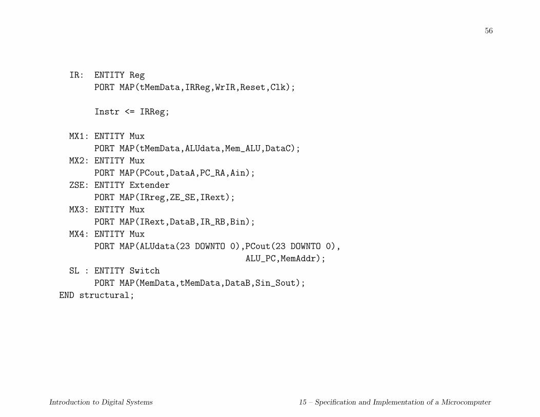
56
IR: ENTITY Reg
PORT MAP(tMemData,IRReg,WrIR,Reset,Clk);
Instr <= IRReg;
MX1: ENTITY Mux
PORT MAP(tMemData,ALUdata,Mem_ALU,DataC);
MX2: ENTITY Mux
PORT MAP(PCout,DataA,PC_RA,Ain);
ZSE: ENTITY Extender
PORT MAP(IRreg,ZE_SE,IRext);
MX3: ENTITY Mux
PORT MAP(IRext,DataB,IR_RB,Bin);
MX4: ENTITY Mux
PORT MAP(ALUdata(23 DOWNTO 0),PCout(23 DOWNTO 0),
ALU_PC,MemAddr);
SL : ENTITY Switch
PORT MAP(MemData,tMemData,DataB,Sin_Sout);
END structural;
Introduction to Digital Systems 15 – Specification and Implementation of a Microcomputer

57µvhdl DESCRIPTION OF REGISTER FILE
LIBRARY ieee;
USE ieee.std_logic_1164.ALL;
USE ieee.std_logic_unsigned.ALL;
USE WORK.comp_pkg.ALL;
ENTITY Reg_File IS
PORT(AddrA, AddrB, AddrC : IN STD_LOGIC_VECTOR(4 DOWNTO 0);
DataA, DataB : OUT WordT;
DataC : IN WordT;
WrC : IN STD_LOGIC ;
Reset, Clk : IN STD_LOGIC);
END Reg_File;
ARCHITECTURE behavioral OF Reg_File IS
TYPE RegFileT IS ARRAY(0 to 31) OF WordT;
SIGNAL GPR : RegFileT ;
BEGIN
PROCESS(AddrA,AddrB) -- output function
CONSTANT RF_delay : TIME := 4 ns;
BEGIN
DataA <= GPR(CONV_INTEGER(AddrA)) AFTER RF_delay;
DataB <= GPR(CONV_INTEGER(AddrB)) AFTER RF_delay;
END PROCESS;
Introduction to Digital Systems 15 – Specification and Implementation of a Microcomputer

58
PROCESS(Reset,Clk) -- transition function
BEGIN
IF (Reset’EVENT and (Reset = ’1’)) THEN
FOR i IN 0 TO 31 LOOP
GPR(i) <= (OTHERS => ’0’);
END LOOP;
END IF;
IF (Clk’EVENT AND Clk = ’1’ AND WrC = ’1’) THEN
GPR(CONV_INTEGER(AddrC)) <= DataC;
END IF;
END PROCESS;
END behavioral;
Introduction to Digital Systems 15 – Specification and Implementation of a Microcomputer

59µvhdl DESCRIPTION OF ALU
LIBRARY ieee;
USE ieee.std_logic_1164.ALL;
USE ieee.std_logic_signed.ALL;
USE WORK.comp_pkg.ALL;
ENTITY ALU IS
PORT(A, B: IN STD_LOGIC_VECTOR(31 DOWNTO 0);
Op : IN STD_LOGIC_VECTOR( 3 DOWNTO 0);
C : OUT STD_LOGIC_VECTOR(31 DOWNTO 0);
Cond: OUT STD_LOGIC_VECTOR( 3 DOWNTO 0));
END ALU;
ARCHITECTURE behavioral OF ALU IS
BEGIN
PROCESS(A,B,Op)
CONSTANT ALU_delay : TIME := 6 ns;
BEGIN
CASE Op IS
WHEN "0000" => C <= (OTHERS => ’0’) AFTER ALU_delay;
WHEN "0001" => C <= A + B AFTER ALU_delay;
WHEN "0010" => C <= A - B AFTER ALU_delay;
WHEN "0011" => C <= (OTHERS => ’0’) AFTER ALU_delay;
WHEN "0100" => C <= A and B AFTER ALU_delay;
WHEN "0101" => C <= A or B AFTER ALU_delay;
WHEN "0110" => C <= A xor B AFTER ALU_delay;
WHEN "0111" => C <= (OTHERS => ’0’) AFTER ALU_delay;
Introduction to Digital Systems 15 – Specification and Implementation of a Microcomputer

60WHEN "1000" => C <= A AFTER ALU_delay;
WHEN "1001" => C <= B AFTER ALU_delay;
WHEN "1010" => C <= A(30 DOWNTO 0) & ’0’ AFTER ALU_delay;
WHEN "1011" => C <= ’0’ & A(31 DOWNTO 1) AFTER ALU_delay;
WHEN "1100" => C <= A(30 DOWNTO 0) & A(31) AFTER ALU_delay;
WHEN "1101" => C <= A(0) & A(31 DOWNTO 1) AFTER ALU_delay;
WHEN "1110" => C <= A + 4 AFTER ALU_delay;
WHEN "1111" => C <= not(A) AFTER ALU_delay;
WHEN OTHERS => NULL;
END CASE;
Cond <= get_cc(A,B,Op) AFTER ALU_delay;
END PROCESS;
END behavioral;
Introduction to Digital Systems 15 – Specification and Implementation of a Microcomputer

61µvhdl DESCRIPTION OF REGISTERS
LIBRARY ieee; USE ieee.std_logic_1164.ALL;
ENTITY Reg IS
PORT(Data_in : IN STD_LOGIC_VECTOR;
Data_out: OUT STD_LOGIC_VECTOR;
Wr : IN STD_LOGIC ;
Reset : IN STD_LOGIC ;
Clk : IN STD_LOGIC);
END Reg;
ARCHITECTURE behavioral OF Reg IS
BEGIN
PROCESS(Wr,Reset,Clk)
CONSTANT Reg_delay: TIME := 2 ns;
VARIABLE BVZero: STD_LOGIC_VECTOR(Data_in’RANGE):= (OTHERS => ’0’);
BEGIN
IF (Reset = ’1’) THEN
Data_out <= BVZero AFTER Reg_delay;
END IF;
IF (Clk’EVENT AND Clk = ’1’ AND Wr = ’1’) THEN
Data_out <= Data_in AFTER Reg_delay;
END IF;
END PROCESS;
END behavioral;
Introduction to Digital Systems 15 – Specification and Implementation of a Microcomputer

62µvhdl DESCRIPTION OF OTHER MODULES: MUX
LIBRARY ieee;
USE ieee.std_logic_1164.ALL;
ENTITY Mux IS
PORT(A_in,B_in: IN STD_LOGIC_VECTOR;
Sel : IN STD_LOGIC ;
Data_out : OUT STD_LOGIC_VECTOR);
END Mux;
ARCHITECTURE behavioral OF Mux IS
BEGIN
PROCESS(A_in, B_in, Sel)
CONSTANT Mux_delay: TIME := 500 ps;
BEGIN
IF (Sel = ’0’) THEN
Data_out <= A_in AFTER Mux_delay;
ELSE
Data_out <= B_in AFTER Mux_delay;
END IF;
END PROCESS;
END behavioral;
Introduction to Digital Systems 15 – Specification and Implementation of a Microcomputer

63µvhdl DESCRIPTION OF EXTENDER
LIBRARY ieee;
USE ieee.std_logic_1164.ALL;
ENTITY Extender IS
PORT(X_in : IN STD_LOGIC_VECTOR(31 DOWNTO 0);
ZE_SE : IN STD_LOGIC ;
X_out : OUT STD_LOGIC_VECTOR(31 DOWNTO 0));
END Extender;
ARCHITECTURE behavioral OF Extender IS
BEGIN
PROCESS(X_in, ZE_SE)
CONSTANT Ext_delay: TIME := 500 ps;
BEGIN
IF (ZE_SE = ’0’) THEN
X_out(31 DOWNTO 16) <= (OTHERS => ’0’) AFTER Ext_delay;
X_out(15 DOWNTO 0) <= X_in(15 DOWNTO 0) AFTER Ext_delay;
ELSE
X_out(31 DOWNTO 16) <= (OTHERS => X_in(15)) AFTER Ext_delay;
X_out(15 DOWNTO 0) <= X_in(15 DOWNTO 0) AFTER Ext_delay;
END IF;
END PROCESS;
END behavioral;
Introduction to Digital Systems 15 – Specification and Implementation of a Microcomputer
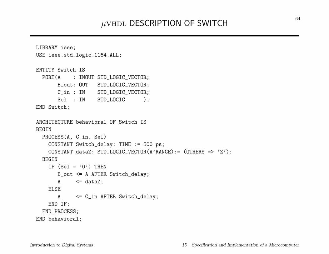
64µvhdl DESCRIPTION OF SWITCH
LIBRARY ieee;
USE ieee.std_logic_1164.ALL;
ENTITY Switch IS
PORT(A : INOUT STD_LOGIC_VECTOR;
B_out: OUT STD_LOGIC_VECTOR;
C_in : IN STD_LOGIC_VECTOR;
Sel : IN STD_LOGIC );
END Switch;
ARCHITECTURE behavioral OF Switch IS
BEGIN
PROCESS(A, C_in, Sel)
CONSTANT Switch_delay: TIME := 500 ps;
CONSTANT dataZ: STD_LOGIC_VECTOR(A’RANGE):= (OTHERS => ’Z’);
BEGIN
IF (Sel = ’0’) THEN
B_out <= A AFTER Switch_delay;
A <= dataZ;
ELSE
A <= C_in AFTER Switch_delay;
END IF;
END PROCESS;
END behavioral;
Introduction to Digital Systems 15 – Specification and Implementation of a Microcomputer

65µvhdl DESCRIPTION OF CONTROL SYSTEM
LIBRARY ieee;
USE ieee.std_logic_1164.ALL;
USE WORK.comp_pkg.ALL;
ENTITY Ctrl_Subsystem IS
PORT(Instr : IN WordT ;
ZE, NG, CY, OV : IN STD_LOGIC ;
AddrA, AddrB, AddrC : OUT STD_LOGIC_VECTOR(4 DOWNTO 0);
ALUOp : OUT STD_LOGIC_VECTOR(3 DOWNTO 0);
WrC, WrPC, WrCR, WrIR : OUT STD_LOGIC ;
Mem_ALU, PC_RA, IR_RB : OUT STD_LOGIC ;
ALU_PC, ZE_SE, Sin_Sout: OUT STD_LOGIC ;
MemRd,MemWr : OUT STD_LOGIC ;
MemLength : OUT STD_LOGIC ;
MemEnable : OUT STD_LOGIC ;
MemRdy : IN STD_LOGIC ;
IORd, IOWr : OUT STD_LOGIC ;
IOLength : OUT STD_LOGIC ;
IOEnable : OUT STD_LOGIC ;
IORdy : IN STD_LOGIC ;
Status : OUT StatusT ;
Clk, Reset : IN STD_LOGIC );
END Ctrl_Subsystem;
Introduction to Digital Systems 15 – Specification and Implementation of a Microcomputer

66
µvhdl DESCRIPTION OF CONTROL SYSTEM (cont.)
LIBRARY ieee;
USE ieee.std_logic_signed.ALL;
ARCHITECTURE behavioral OF Ctrl_Subsystem IS
SIGNAL State: StatusT;
BEGIN
PROCESS -- transition function
ALIAS Opcode : STD_LOGIC_VECTOR(5 DOWNTO 0) IS Instr(31 DOWNTO 26);
CONSTANT Reset_delay: TIME:= 500 ps ;
CONSTANT Ctrl_delay : TIME:= 500 ps ;
BEGIN
WAIT ON Clk,Reset;
IF (Reset’EVENT AND Reset = ’1’) THEN
State <= p_reset AFTER Reset_delay;
Status <= p_reset AFTER Reset_delay;
WAIT UNTIL Clk = ’1’;
END IF;
IF (Clk’EVENT) AND (Clk = ’1’) THEN
CASE State IS
WHEN p_reset => Status <= fetch AFTER Ctrl_delay;
State <= fetch AFTER Ctrl_delay;
WHEN fetch => Status <= execute AFTER Ctrl_delay;
State <= execute AFTER Ctrl_delay;
Introduction to Digital Systems 15 – Specification and Implementation of a Microcomputer

67
WHEN execute => CASE Opcode IS
WHEN "100000" | "100001" => State <= memop AFTER Ctrl_delay;
Status <= memop AFTER Ctrl_delay;
WHEN "100010" | "100011" => State <= memop AFTER Ctrl_delay;
Status <= memop AFTER Ctrl_delay;
WHEN OTHERS => State <= fetch AFTER Ctrl_delay;
Status <= fetch AFTER Ctrl_delay;
END CASE;
WHEN memop | ioop => Status <= fetch AFTER Ctrl_delay;
State <= fetch AFTER Ctrl_delay;
WHEN undef => NULL;
END CASE;
END IF;
END PROCESS;
PROCESS(State,Instr,MemRdy) -- output function
ALIAS Opcode : STD_LOGIC_VECTOR( 5 DOWNTO 0) IS Instr(31 DOWNTO 26);
ALIAS Imm : STD_LOGIC_VECTOR(15 DOWNTO 0) IS Instr(15 DOWNTO 0);
ALIAS D : STD_LOGIC_VECTOR(15 DOWNTO 0) IS Instr(15 DOWNTO 0);
ALIAS PN : STD_LOGIC_VECTOR(10 DOWNTO 0) IS Instr(10 DOWNTO 0);
CONSTANT Dec_delay : TIME:= 3 ns;
CONSTANT Ctrl_delay : TIME:= 500 ps;
CONSTANT MemRd_delay: TIME:= 2500 ps;
CONSTANT MemRd_pulse: TIME:= MemRd_delay + 3 ns ;
CONSTANT MemWr_delay: TIME:= 2500 ps;
CONSTANT MemWr_pulse: TIME:= MemWr_delay + 3 ns ;
Introduction to Digital Systems 15 – Specification and Implementation of a Microcomputer
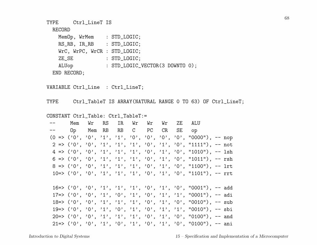
68TYPE Ctrl_LineT IS
RECORD
MemOp, WrMem : STD_LOGIC;
RS_RB, IR_RB : STD_LOGIC;
WrC, WrPC, WrCR : STD_LOGIC;
ZE_SE : STD_LOGIC;
ALUop : STD_LOGIC_VECTOR(3 DOWNTO 0);
END RECORD;
VARIABLE Ctrl_Line : Ctrl_LineT;
TYPE Ctrl_TableT IS ARRAY(NATURAL RANGE 0 TO 63) OF Ctrl_LineT;
CONSTANT Ctrl_Table: Ctrl_TableT:=
-- Mem Wr RS IR Wr Wr Wr ZE ALU
-- Op Mem RB RB C PC CR SE op
(0 => (’0’, ’0’, ’1’, ’1’, ’0’, ’0’, ’0’, ’0’, "0000"), -- nop
2 => (’0’, ’0’, ’1’, ’1’, ’1’, ’0’, ’1’, ’0’, "1111"), -- not
4 => (’0’, ’0’, ’1’, ’1’, ’1’, ’0’, ’1’, ’0’, "1010"), -- lsh
6 => (’0’, ’0’, ’1’, ’1’, ’1’, ’0’, ’1’, ’0’, "1011"), -- rsh
8 => (’0’, ’0’, ’1’, ’1’, ’1’, ’0’, ’1’, ’0’, "1100"), -- lrt
10=> (’0’, ’0’, ’1’, ’1’, ’1’, ’0’, ’1’, ’0’, "1101"), -- rrt
16=> (’0’, ’0’, ’1’, ’1’, ’1’, ’0’, ’1’, ’0’, "0001"), -- add
17=> (’0’, ’0’, ’1’, ’0’, ’1’, ’0’, ’1’, ’1’, "0001"), -- adi
18=> (’0’, ’0’, ’1’, ’1’, ’1’, ’0’, ’1’, ’0’, "0010"), -- sub
19=> (’0’, ’0’, ’1’, ’0’, ’1’, ’0’, ’1’, ’1’, "0010"), -- sbi
20=> (’0’, ’0’, ’1’, ’1’, ’1’, ’0’, ’1’, ’0’, "0100"), -- and
21=> (’0’, ’0’, ’1’, ’0’, ’1’, ’0’, ’1’, ’0’, "0100"), -- ani
Introduction to Digital Systems 15 – Specification and Implementation of a Microcomputer

69
22=> (’0’, ’0’, ’1’, ’1’, ’1’, ’0’, ’1’, ’0’, "0101"), -- or
23=> (’0’, ’0’, ’1’, ’0’, ’1’, ’0’, ’1’, ’0’, "0101"), -- ori
24=> (’0’, ’0’, ’1’, ’1’, ’1’, ’0’, ’1’, ’0’, "0110"), -- xor
25=> (’0’, ’0’, ’1’, ’0’, ’1’, ’0’, ’1’, ’0’, "0110"), -- xri
32=> (’1’, ’0’, ’0’, ’0’, ’1’, ’0’, ’0’, ’1’, "0001"), -- ldb
33=> (’1’, ’0’, ’0’, ’0’, ’1’, ’0’, ’0’, ’1’, "0001"), -- ldw
34=> (’1’, ’1’, ’0’, ’0’, ’0’, ’0’, ’0’, ’1’, "0001"), -- stb
35=> (’1’, ’1’, ’0’, ’0’, ’0’, ’0’, ’0’, ’1’, "0001"), -- stw
36=> (’1’, ’0’, ’0’, ’1’, ’1’, ’0’, ’0’, ’0’, "1001"), -- irb
37=> (’1’, ’0’, ’0’, ’1’, ’1’, ’0’, ’0’, ’0’, "1001"), -- irw
38=> (’1’, ’1’, ’0’, ’1’, ’0’, ’0’, ’0’, ’0’, "1001"), -- iwb
39=> (’1’, ’1’, ’0’, ’1’, ’0’, ’0’, ’0’, ’0’, "1001"), -- iww
56=> (’0’, ’0’, ’1’, ’0’, ’0’, ’1’, ’0’, ’1’, "0001"), -- br
57=> (’0’, ’0’, ’1’, ’0’, ’0’, ’1’, ’0’, ’1’, "1000"), -- bri
48=> (’0’, ’0’, ’1’, ’0’, ’0’, ’1’, ’0’, ’1’, "0001"), -- brp
49=> (’0’, ’0’, ’1’, ’0’, ’0’, ’1’, ’0’, ’1’, "0001"), -- brn
50=> (’0’, ’0’, ’1’, ’0’, ’0’, ’1’, ’0’, ’1’, "0001"), -- bnz
51=> (’0’, ’0’, ’1’, ’0’, ’0’, ’1’, ’0’, ’1’, "0001"), -- brz
52=> (’0’, ’0’, ’1’, ’0’, ’0’, ’1’, ’0’, ’1’, "0001"), -- bnc
53=> (’0’, ’0’, ’1’, ’0’, ’0’, ’1’, ’0’, ’1’, "0001"), -- brc
54=> (’0’, ’0’, ’1’, ’0’, ’0’, ’1’, ’0’, ’1’, "0001"), -- bnv
55=> (’0’, ’0’, ’1’, ’0’, ’0’, ’1’, ’0’, ’1’, "0001"), -- brv
OTHERS => (’0’, ’0’, ’1’, ’1’, ’0’, ’0’, ’0’, ’1’, "0000")
);
Introduction to Digital Systems 15 – Specification and Implementation of a Microcomputer

70
BEGIN
IF (State’EVENT) THEN
CASE State IS
WHEN undef => NULL;
WHEN p_reset => ALUOp <= "0000";
MemRd <= ’0’; MemWr <= ’0’;
MemEnable <= ’0’; MemLength <= ’0’;
IORd <= ’0’; IOWr <= ’0’;
IOEnable <= ’0’; IOLength <= ’0’;
WHEN fetch =>
-- disable write signals from previous cycle
WrCR <= ’0’ AFTER Ctrl_delay;
WrC <= ’0’ AFTER Ctrl_delay;
-- fetch instruction
ALU_PC <= ’1’ AFTER Ctrl_delay;
MemLength<= ’1’ AFTER Ctrl_delay;
MemEnable<= ’1’ AFTER Ctrl_delay;
MemRd <= ’1’ AFTER MemRd_delay, ’0’ AFTER MemRd_pulse;
Sin_Sout <= ’0’ AFTER Ctrl_delay; -- switch in
-- increment PC
PC_RA <= ’0’ AFTER Ctrl_delay;
ALUop <= "1110" AFTER Ctrl_delay; -- PC + 4
WrIR <= ’1’ AFTER Ctrl_delay;
WrPC <= ’1’ AFTER Ctrl_delay;
Introduction to Digital Systems 15 – Specification and Implementation of a Microcomputer
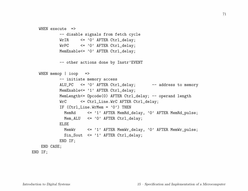
71
WHEN execute =>
-- disable signals from fetch cycle
WrIR <= ’0’ AFTER Ctrl_delay;
WrPC <= ’0’ AFTER Ctrl_delay;
MemEnable<= ’0’ AFTER Ctrl_delay;
-- other actions done by Instr’EVENT
WHEN memop | ioop =>
-- initiate memory access
ALU_PC <= ’0’ AFTER Ctrl_delay; -- address to memory
MemEnable<= ’1’ AFTER Ctrl_delay;
MemLength<= Opcode(0) AFTER Ctrl_delay; -- operand length
WrC <= Ctrl_Line.WrC AFTER Ctrl_delay;
IF (Ctrl_Line.WrMem = ’0’) THEN
MemRd <= ’1’ AFTER MemRd_delay, ’0’ AFTER MemRd_pulse;
Mem_ALU <= ’0’ AFTER Ctrl_delay;
ELSE
MemWr <= ’1’ AFTER MemWr_delay, ’0’ AFTER MemWr_pulse;
Sin_Sout <= ’1’ AFTER Ctrl_delay;
END IF;
END CASE;
END IF;
Introduction to Digital Systems 15 – Specification and Implementation of a Microcomputer
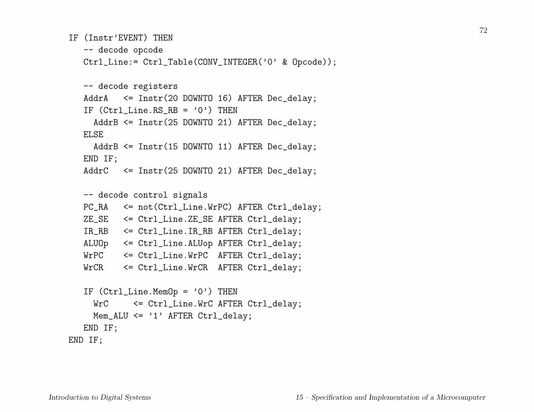
72IF (Instr’EVENT) THEN
-- decode opcode
Ctrl_Line:= Ctrl_Table(CONV_INTEGER(’0’ & Opcode));
-- decode registers
AddrA <= Instr(20 DOWNTO 16) AFTER Dec_delay;
IF (Ctrl_Line.RS_RB = ’0’) THEN
AddrB <= Instr(25 DOWNTO 21) AFTER Dec_delay;
ELSE
AddrB <= Instr(15 DOWNTO 11) AFTER Dec_delay;
END IF;
AddrC <= Instr(25 DOWNTO 21) AFTER Dec_delay;
-- decode control signals
PC_RA <= not(Ctrl_Line.WrPC) AFTER Ctrl_delay;
ZE_SE <= Ctrl_Line.ZE_SE AFTER Ctrl_delay;
IR_RB <= Ctrl_Line.IR_RB AFTER Ctrl_delay;
ALUOp <= Ctrl_Line.ALUop AFTER Ctrl_delay;
WrPC <= Ctrl_Line.WrPC AFTER Ctrl_delay;
WrCR <= Ctrl_Line.WrCR AFTER Ctrl_delay;
IF (Ctrl_Line.MemOp = ’0’) THEN
WrC <= Ctrl_Line.WrC AFTER Ctrl_delay;
Mem_ALU <= ’1’ AFTER Ctrl_delay;
END IF;
END IF;
Introduction to Digital Systems 15 – Specification and Implementation of a Microcomputer
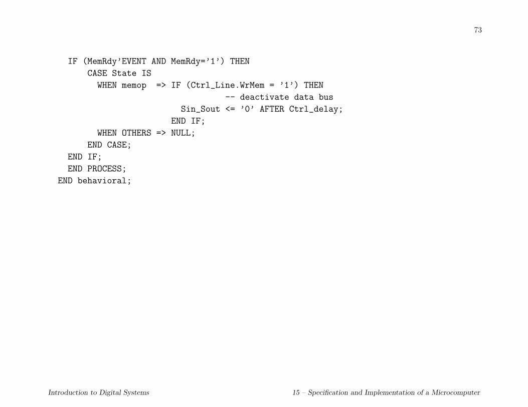
73
IF (MemRdy’EVENT AND MemRdy=’1’) THEN
CASE State IS
WHEN memop => IF (Ctrl_Line.WrMem = ’1’) THEN
-- deactivate data bus
Sin_Sout <= ’0’ AFTER Ctrl_delay;
END IF;
WHEN OTHERS => NULL;
END CASE;
END IF;
END PROCESS;
END behavioral;
Introduction to Digital Systems 15 – Specification and Implementation of a Microcomputer