1 sites input using the integrated development environment __________________________ sites 2005...
TRANSCRIPT

1
SITES INPUTSITES INPUTusing the
Integrated Development EnvironmentIntegrated Development Environment
____________________________________________________SITES 2005SITES 2005
INTEGRATED DEVELOPMENT ENVIRONMENTINTEGRATED DEVELOPMENT ENVIRONMENTfor
WATER RESOURCE SITE ANALYSIS

2
OBJECTIVEOBJECTIVE
• Understand SITES inputs • Navigate Integrated Development
Environment (IDE)

3
Starting Out Starting Out
1. Start a new project2. Create initial data file3. Modify original data file
for other runs

4
New ProjectNew Project
• Browse parent directory
• Type name of the new project (folder)

5
Home ScreenHome ScreenFile MenuFile Menu
•Proceed – select Proceed – select CContinueontinue

6
Global WatershedGlobal Watershed Data Data
Determines data to enter and analyses to perform

7
Watershed Schematic Watershed Schematic
Hydrologic Model• Structures• Subwatersheds• Channel reaches• Junctions• Click icon menu
to add element to schematic
•Single Structure•Uncontrolled Drainage Area
Dbl-click to edit element

8
Watershed InfoWatershed Info

9
Hydrologic Data OptionsHydrologic Data Options
Rainfall Hydrographs
Compute Areal
Correction(SITES)
Enter Areally
Corrected Rainfall

10
Structure Data TableStructure Data Table
Normal Entries
(SA or Vol)
Norm
al
En
tries
Sp
ecia
l
Sp
ecia
l• 20 entries max20 entries max

11
Structure Data TableStructure Data Table
• Enter PS rating Special riser/conduit not defined by
SITES First row must be crest of PS
• Enter AS rating Preferred to let SITES create the AS
rating Crest of AS spwy is line preceding 1st
AS discharge entry
12
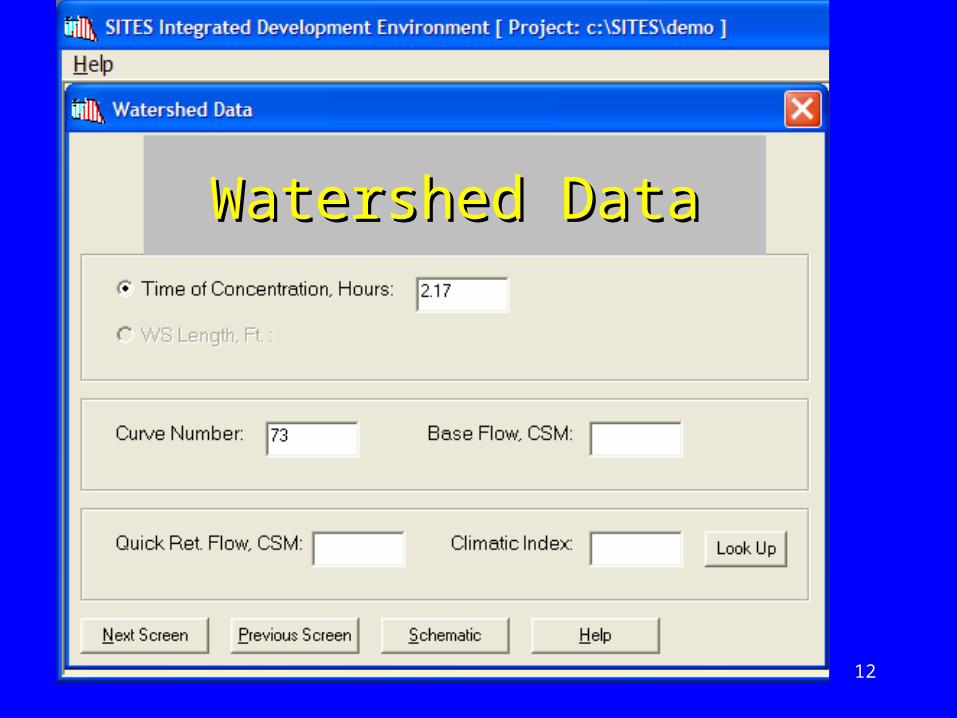
Watershed DataWatershed Data
13
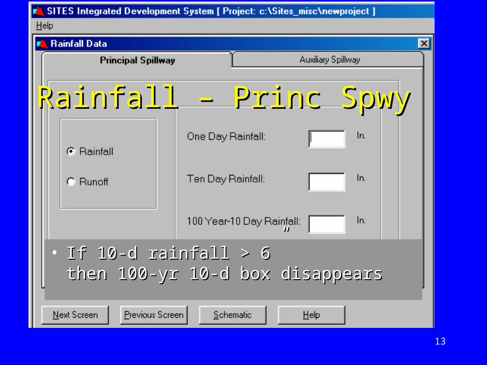
Rainfall – Princ SpwyRainfall – Princ Spwy
• If 10-d rainfall > 6” If 10-d rainfall > 6” then 100-yr 10-d box disappearsthen 100-yr 10-d box disappears
14
PS Rainfall & RunoffPS Rainfall & Runoff
• Rainfall/Runoff Screen ONLY applies to PSH No PSH run, screen doesn’t appear
• RUNOFF option used where snowmelt flooding should be checked North-central and Northeastern US AZ not included See TR-60 Figure 2-1

15
Rainfall – Aux SpwyRainfall – Aux Spwy
% PMP
16
Standard DistributionsStandard Distributions
• NRCS 6 hr• NRCS 24 hr Type I• NRCS 24 hr Type Ia• NRCS 24 hr Type II• NRCS 24 hr Type III
• Can enter non-standard distribution

17
Distribution TableDistribution Table• Dimensionless or rainfall depth• Values increasing

18
Pool Data ScreenPool Data Screen

19
Pool DataPool Data
• Flood Pool Sediment Optional entry Value > crest of PS Generally FP sediment = PS crest
• Permanent Pool Optional entry Sets wave berm elevation
20
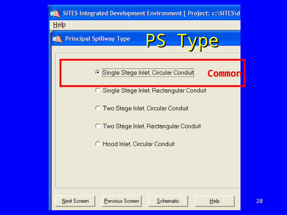
PS TypePS Type
Common

21
PS InletPS Inlet
• Ke -energy loss inlet entrance to just inside the conduit
• See NRCS Design Note 8

22
PS ConduitPS Conduit
• Constant• CL pipe
outlet

23
Valley ElevationsValley ElevationsAS can erode down to “Elev of Valley Floor”
Dam Height for classification
Profile for embankment quantity computation (optional)

24
Profile Valley XSCProfile Valley XSCStripping depth
99 profile station/elev entries

25
Embankment DataEmbankment Data

26
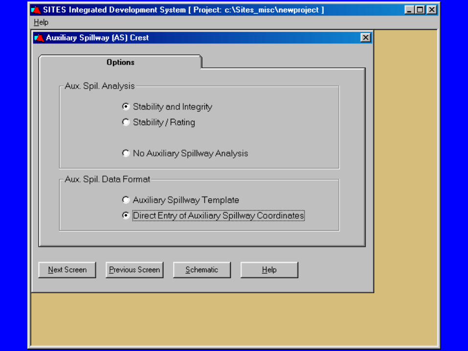
AS Crest OptionsAS Crest Options

27
AS Crest DataAS Crest Data
• PSH checked on Global WS Data SITES sets crest of AS
• PSH unchecked on Global WS Data screen User specifies AS crest elevation

28
Tie StationTie Station
• Tie station is downstream end of level crest of auxiliary spillway
• Ties auxiliary spillway crest information with geologic materials

29
AS Inlet TemplateAS Inlet Template
Distance & Depth - from Tie Station
30
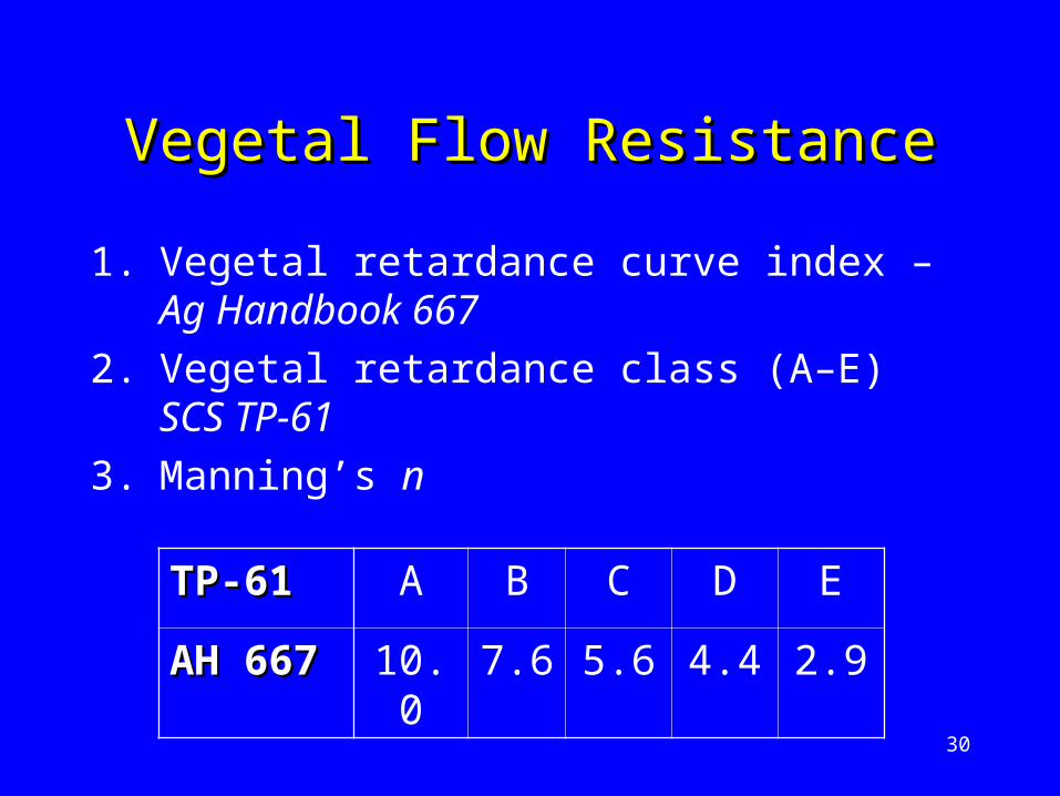
Vegetal Flow ResistanceVegetal Flow Resistance
1. Vegetal retardance curve index – Ag Handbook 667
2. Vegetal retardance class (A–E) SCS TP-61
3. Manning’s n
TP-61TP-61 A B C D E
AH 667AH 667 10.0 7.6 5.6 4.4 2.9
31
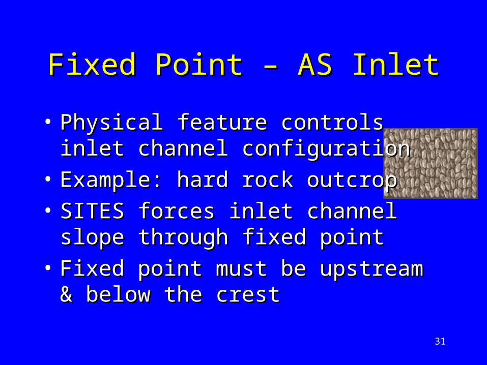
Fixed Point – AS InletFixed Point – AS Inlet
• Physical feature controls inlet Physical feature controls inlet channel configurationchannel configuration
• Example: hard rock outcrop Example: hard rock outcrop • SITES forces inlet channel slope SITES forces inlet channel slope
through fixed pointthrough fixed point• Fixed point must be upstream & Fixed point must be upstream &
below the crestbelow the crest
32
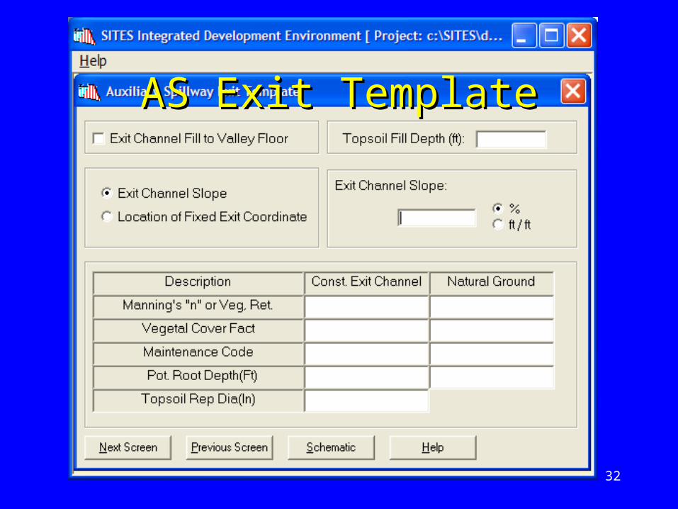
AS Exit TemplateAS Exit Template
33
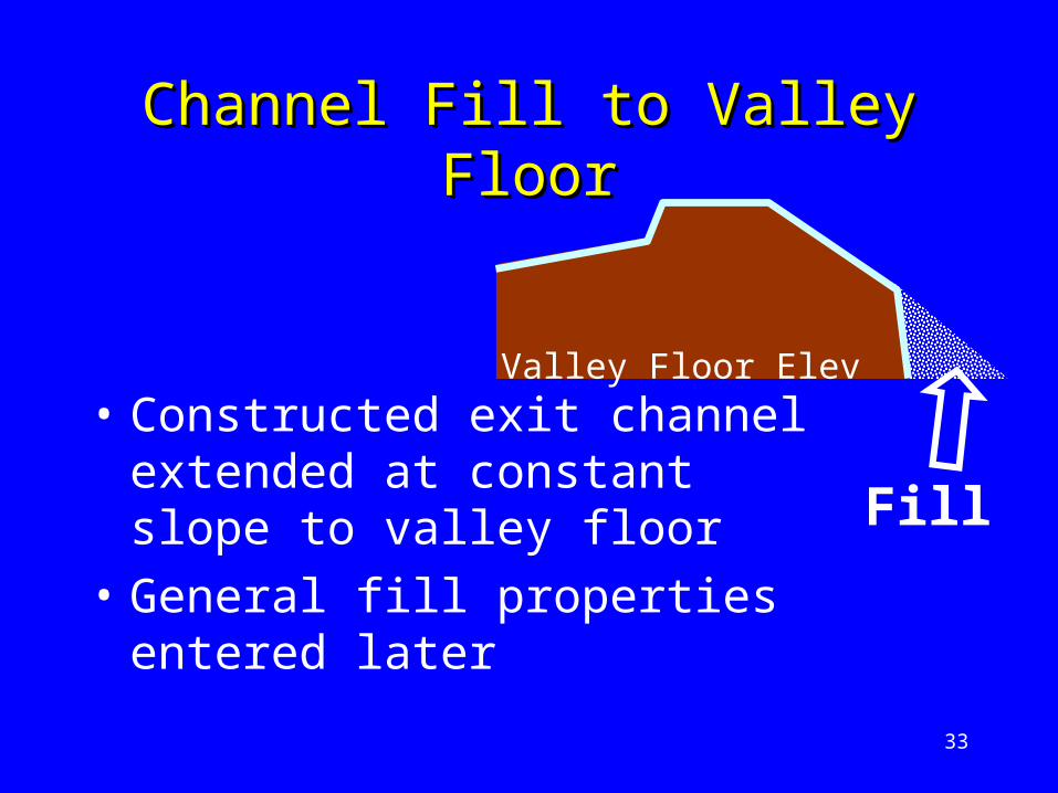
Channel Fill to Valley FloorChannel Fill to Valley Floor
Fill
• Constructed exit channel extended at constant slope to valley floor
• General fill properties entered later
Valley Floor Elev

34
Vegetal Cover Factor & Vegetal Cover Factor & Maintenance CodeMaintenance Code
• Used to compute effective stress Used to compute effective stress on erodible boundary for uniform on erodible boundary for uniform vegetal conditionsvegetal conditions
• Discontinuities in cover minimize Discontinuities in cover minimize effect of cover factor (MC 2 or 3)effect of cover factor (MC 2 or 3) Erosion occurs in areas without coverErosion occurs in areas without cover
• See Ag Handbook 667See Ag Handbook 667

35
Potential Rooting DepthPotential Rooting Depth& Topsoil Diameter& Topsoil Diameter
• Rooting Depth > 1’ – protected• Rooting Depth < 1’ – strips away• Topsoil representative diameter only
for stability analysis Constructed exit channel only
(no fill in natural ground) Coarse-grained materials only
(d75>0.05 inches)

36
AS Cross-sectionAS Cross-sectionTrapezoidal
3 Methods
Peak SDH
Peak SDH

37
AS MaterialsAS Materials

38
AS Materials NotesAS Materials Notes• Integrity evaluation of auxiliary spillway
Describe materials exposed to erosive attack Geologic profile through spillway Spillway centerline profile?? Erosion occurs at weakest materials Input weakest geologic profile in spillway
• Material Description only for labeling Be descriptive “CL1, CH2, Limestone” are better than 1, 2

39
PI - Dry Density - % ClayPI - Dry Density - % Clay
• PI for time of phase 1 (surface-vegetation) failure
• PI most important for materials initially exposed at spillway surface
• Dry density and percent clay determe the erosion rate coefficient of downcutting for concentrated flow and headcuts in cohesive materials
• Use either % clay or detach rate (jet erosion test)

40
Rep Diameter & KRep Diameter & Khh
• Size of material detached as single unit
Fine grained materials & sediments - d75
Large materials -
Governs computed threshold where surface shear
detaches material in concentrated flow or headcut
downcutting
• Headcut erodibility index (Kh) governs threshold and rate for headcut advance
3 BlockDetachableofVolume

41
SPILLWAY GEOLOGY
STATION
EL
EV
AT
ION
, ft
, ft
AS Geology PlotAS Geology Plot

42
AS TopsoilAS Topsoil

43
Output OptionsOutput Options

44
SDH FBH OnlySDH FBH Only
45
46
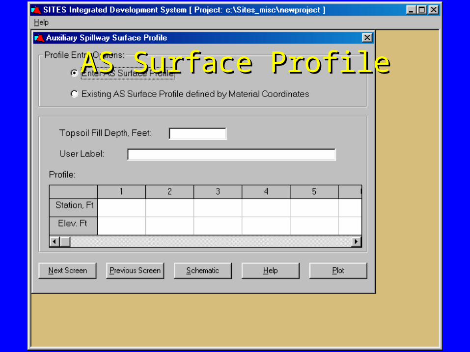
AS Surface ProfileAS Surface Profile

47
AS Surface ConditionsAS Surface Conditions

48
After the desired input data set is developed, the data is normally stored under a new file name.
Save As . . .Save As . . .

49
Input TipsInput Tips
• Create project directory for each dam• Select projects from MRU list• Descriptive file names help• Use comments to document the
alternative• Let SITES be the file manager• Send input file (*.d2c) to reviewer• Send input file (*.d2c) to reviewer

50
Typical Opening SequenceTypical Opening Sequence
• Open Project Directory (select from list)• Open File (select file, NOT folder)
SITES build creates a folder with same name as input file
• Continue – Next Screen Schematic• Dbl-click design structure
User spends most time editing design structure

51
Jump to ScreenJump to Screen
• Right-click in empty area• Select specific screen

52
Typical Post-edit SequenceTypical Post-edit Sequence
• Schematic• Home Screen• Save As . . . (enter filename)• Build File
SITES builds folder and places all output files into the folder

53
Pictures of the year by NBC
EndEnd
Don’t forget to send input file (*.d2c) to reviewer!