1-s2.0-s0038092x13000571-main.pdf
TRANSCRIPT

Available online at www.sciencedirect.com
www.elsevier.com/locate/solener
Solar Energy 91 (2013) 242–255
Thermal performance analysis of a line-focus Fresnel lens solarcollector using different cavity receivers
W.T. Xie a, Y.J. Dai b,⇑, R.Z. Wang b
a Research Center of Solar Power and Refrigeration, Shanghai Jiao Tong University, Shanghai 200240, PR Chinab Institute of Refrigeration and Cryogenics, Shanghai Jiao Tong University, Shanghai 200240, PR China
Received 25 February 2012; received in revised form 30 January 2013; accepted 31 January 2013Available online 22 March 2013
Communicated by: Associate Editor Brian Norton
Abstract
In this paper, a line-focus Fresnel lens solar collector using different cavity receivers are studied and compared. Thermal performanceof the line-focus Fresnel lens solar collector with each cavity receiver is studied experimentally at different temperature levels. The effi-ciency factors and heat removal factors of Fresnel lens solar collectors using different kinds of line-focus cavity receivers are obtainedboth theoretically and experimentally. Eight kinds of cavity receivers, namely: triangular, arc-shaped, rectangular, semicircular, positivetrapezoidal, reverse trapezoidal, hetero trapezoidal and convex, are tested and analyzed. It is found that the theoretical results agree wellwith the test results. For the line-focus Fresnel lens solar collector, the triangular cavity receiver shows the best thermal performance. Thehighest experimental heat removal factor is about 0.805 when the operation temperature is 180 �C. Results show that under given oper-ation conditions, the optimum width of cavity aperture, the optimum inside diameter of the receiver tube and the optimum vertex angleof the cross section of the receiver are 50 mm, 18 mm and 60�, respectively. It is recommended that the geometrical concentration ratio ofthe studied Fresnel lens solar collector should be more than 55. The experimental heat removal factors for triangular cavity receivers areincreased to 0.879 (using rectangular pipelines as the absorber plate) and 0.873 (using tube bundles as the absorber plate) respectively,after optimization.� 2013 Elsevier Ltd. All rights reserved.
Keywords: Solar energy; Fresnel lens solar collector; Line-focus; Cavity receiver; Heat removal factor
1. Introduction
Fresnel lens was first demonstrated as a collimator inlighthouses by Augustine Jean Fresnel (Leutz and Suzuki,2001) in 1822, since then, it has been widely used in manyfields. In solar thermal conversion applications, Fresnel lenshas advantages of small volume, light weight, suitability formass production at low cost, and effectively increasing theenergy density. Fresnel lenses have been becoming animportant choice for solar thermal conversion applications(Xie et al., 2011). Fresnel lens was originally made from
0038-092X/$ - see front matter � 2013 Elsevier Ltd. All rights reserved.
http://dx.doi.org/10.1016/j.solener.2013.01.029
⇑ Corresponding author. Tel.: +86 21 34204358; fax: +86 21 34206814.E-mail address: [email protected] (Y.J. Dai).
glass, but now is produced by injection molding a plasticmaterials that have optical specifications similar to glass,such as acrylic, polycarbonate and polymethylmethacrylate(PMMA), become available in the 1950s (Xie et al., 2011).Moreover, Fresnel lenses can be scaled as large or as smallas desired, restricted only by fabrication capabilities (Val-miki et al., 2011). So, the processing parameters (melt tem-perature, mold temperature, packing pressure, and injectionspeed) should be investigated in fabrication of Fresnel lenssolar collector (Kuo, 2012). Generally, there are two typesof Fresnel lenses: line-focus Fresnel lens and point-focusFresnel lens. Line-focus Fresnel lens is usually usedfor low concentrated and medium concentrated (thegeometrical concentration ratio is less than 100) solarthermal, photovoltaic or photovoltaic/thermal systems
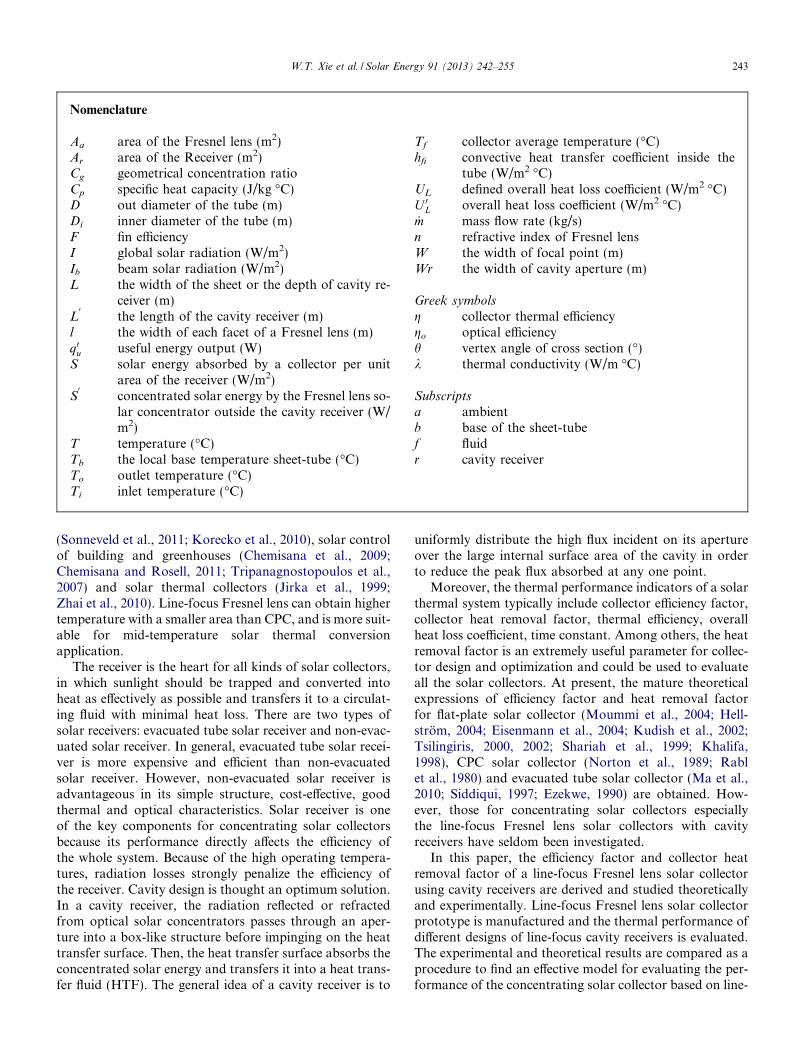
Nomenclature
Aa area of the Fresnel lens (m2)Ar area of the Receiver (m2)Cg geometrical concentration ratioCp specific heat capacity (J/kg �C)D out diameter of the tube (m)Di inner diameter of the tube (m)F fin efficiencyI global solar radiation (W/m2)Ib beam solar radiation (W/m2)L the width of the sheet or the depth of cavity re-
ceiver (m)L0
the length of the cavity receiver (m)l the width of each facet of a Fresnel lens (m)q0u useful energy output (W)S solar energy absorbed by a collector per unit
area of the receiver (W/m2)S0
concentrated solar energy by the Fresnel lens so-lar concentrator outside the cavity receiver (W/m2)
T temperature (�C)Tb the local base temperature sheet-tube (�C)To outlet temperature (�C)Ti inlet temperature (�C)
Tf collector average temperature (�C)hfi convective heat transfer coefficient inside the
tube (W/m2 �C)UL defined overall heat loss coefficient (W/m2 �C)U 0L overall heat loss coefficient (W/m2 �C)_m mass flow rate (kg/s)n refractive index of Fresnel lensW the width of focal point (m)Wr the width of cavity aperture (m)
Greek symbols
g collector thermal efficiencygo optical efficiencyh vertex angle of cross section (�)k thermal conductivity (W/m �C)
Subscripts
a ambientb base of the sheet-tubef fluidr cavity receiver
W.T. Xie et al. / Solar Energy 91 (2013) 242–255 243
(Sonneveld et al., 2011; Korecko et al., 2010), solar controlof building and greenhouses (Chemisana et al., 2009;Chemisana and Rosell, 2011; Tripanagnostopoulos et al.,2007) and solar thermal collectors (Jirka et al., 1999;Zhai et al., 2010). Line-focus Fresnel lens can obtain highertemperature with a smaller area than CPC, and is more suit-able for mid-temperature solar thermal conversionapplication.
The receiver is the heart for all kinds of solar collectors,in which sunlight should be trapped and converted intoheat as effectively as possible and transfers it to a circulat-ing fluid with minimal heat loss. There are two types ofsolar receivers: evacuated tube solar receiver and non-evac-uated solar receiver. In general, evacuated tube solar recei-ver is more expensive and efficient than non-evacuatedsolar receiver. However, non-evacuated solar receiver isadvantageous in its simple structure, cost-effective, goodthermal and optical characteristics. Solar receiver is oneof the key components for concentrating solar collectorsbecause its performance directly affects the efficiency ofthe whole system. Because of the high operating tempera-tures, radiation losses strongly penalize the efficiency ofthe receiver. Cavity design is thought an optimum solution.In a cavity receiver, the radiation reflected or refractedfrom optical solar concentrators passes through an aper-ture into a box-like structure before impinging on the heattransfer surface. Then, the heat transfer surface absorbs theconcentrated solar energy and transfers it into a heat trans-fer fluid (HTF). The general idea of a cavity receiver is to
uniformly distribute the high flux incident on its apertureover the large internal surface area of the cavity in orderto reduce the peak flux absorbed at any one point.
Moreover, the thermal performance indicators of a solarthermal system typically include collector efficiency factor,collector heat removal factor, thermal efficiency, overallheat loss coefficient, time constant. Among others, the heatremoval factor is an extremely useful parameter for collec-tor design and optimization and could be used to evaluateall the solar collectors. At present, the mature theoreticalexpressions of efficiency factor and heat removal factorfor flat-plate solar collector (Moummi et al., 2004; Hell-strom, 2004; Eisenmann et al., 2004; Kudish et al., 2002;Tsilingiris, 2000, 2002; Shariah et al., 1999; Khalifa,1998), CPC solar collector (Norton et al., 1989; Rablet al., 1980) and evacuated tube solar collector (Ma et al.,2010; Siddiqui, 1997; Ezekwe, 1990) are obtained. How-ever, those for concentrating solar collectors especiallythe line-focus Fresnel lens solar collectors with cavityreceivers have seldom been investigated.
In this paper, the efficiency factor and collector heatremoval factor of a line-focus Fresnel lens solar collectorusing cavity receivers are derived and studied theoreticallyand experimentally. Line-focus Fresnel lens solar collectorprototype is manufactured and the thermal performance ofdifferent designs of line-focus cavity receivers is evaluated.The experimental and theoretical results are compared as aprocedure to find an effective model for evaluating the per-formance of the concentrating solar collector based on line-

Line-focus Fresnel lens
Cavity receiver
Thermostat
Tracking unit
Heat exchanger
Pyranometer
Fig. 2. Photos of the line-focus Fresnel lens solar collector test rig.
244 W.T. Xie et al. / Solar Energy 91 (2013) 242–255
focus Fresnel lens and determining the optimal cavity ofthe receiver for solar thermal applications.
2. Line-focus Fresnel lens solar collector
The line-focus Fresnel lens solar collector prototypeusing different cavity receivers was built. The schematicdiagram of the test rig is shown in Fig. 1. The practical testrig, which is shown in Fig. 2, consists of a line-focus Fres-nel lens solar concentrator whose geometrical concentra-tion ratio is about 15, a line-focus cavity receiver and asingle-axis tracking unit, a thermostat oil bath, a circulat-ing oil pump, a ball valve, a heat exchanger, etc. In thiswork, eight kinds of line-focus cavity receivers, namely, tri-angular, arc-shaped, rectangular, semicircular, positivetrapezoidal, reverse trapezoidal, hetero trapezoidal andconvex, are tested so as to compare their thermal perfor-mance theoretically and experimentally. The ambient con-ditions were: the minimum direct normal solar irradianceaveraged over each test period was 630 W/m2 and the dif-ference between the maximum and minimum irradiancevalues was less than 200 W/m2; the allowable range ofthe ambient temperature was between 0 �C and 30 �Cand the maximum allowable variation in ambient temper-ature for quasi-steady state conditions was ±2.0 �C;the average wind speed across the collector was less than4 m/s.
2.1. Geometrical concentration ratio
The surface of a Fresnel lens is made up of many smallconcentric grooves or parallel groves which behave likemany prisms. A schematic diagram of a line-focus Fresnellens for solar thermal application is illustrated in Fig. 3. Inthis case, the flat side of the Fresnel lens is facing up toreceive the solar rays without chromatic aberration andspherical aberration. It is assumed that the receiver is aplane. The geometrical concentration ratio is defined as:
·
Line-focus Fresnel
lens
Cavity receiver
Heat exchanger
Valve
Thermostat
Pump
Sunlight
Ta
To TiF
Ib
Computer
Fig. 1. Schematic diagram of the line-focus Fresnel lens solar collector testrig.
Cg ¼Aa
Ar¼ b
Wð1Þ
If all the solar radiation refracted by the Fresnel lenscould fall on the plane, the condition is:
W 0 P 2Rn tan ds ð2Þ
where ds is the half field angle between the solar and theearth which is 160. Because b and b
0are almost the same,
then:
tan b � tan b0 ¼ WW 0 ð3Þ
So the geometrical concentration ratio of the Fresnellens is:
Cg ¼b
2Rn tan ds tan bð4Þ
According to the geometrical relationship in Fig. 3
Rn ¼
ffiffiffiffiffiffiffiffiffiffiffiffiffiffiffiffiffiffiffiffiffiffiffiffiffiffiffiffiffiffiffiffiffiffiffiffiffiffiffiffiffiffiffiffiffiffiffiffir2
2 þ f� tþ l2
tan a
� �2s
ð5Þ
tan b ¼ r2
f� tþ l2
tan að6Þ
Substituting Rn and tan b into Eq. (4), then:
Cg ¼107:4b f� tþ l
2tan a
� �r2
ffiffiffiffiffiffiffiffiffiffiffiffiffiffiffiffiffiffiffiffiffiffiffiffiffiffiffiffiffiffiffiffiffiffiffiffiffiffiffiffiffiffiffiffir2
2 þ f� tþ l2
tan a� �2
q ð7Þ
where a is the slope angle of each facet in the Fresnel lens.Finally, the geometrical concentration ratio of a line-focusFresnel lens is obtained.
2.2. Cavity receivers
Fig. 4 shows eight kinds of line-focus cavity receivers. Thereceiver pipes are treated with selective coating and placed ina cuboid cavity. The aperture of the cavity is covered with a

Facet of Fresnel lens
Focal plane
Fig. 3. Schematic diagram of a line-focus Fresnel lens for solar thermal application.
W.T. Xie et al. / Solar Energy 91 (2013) 242–255 245
ultra-white plane glass with the thickness is 2 mm and thetransmissivity is about 0.915 to reduce heat loss.
3. Collector efficiency factors and heat removal factors
The collector efficiency factor F0 represents the ratio ofthe actual useful energy gain to the useful gains that wouldresult if the collector absorbing surface was at the localfluid temperature. The collector efficiency factor F
0is the
physical quantity of collector heat exchange structure.However, the collector heat removal factor FR relates theactual useful energy gain of a collector to the useful gainif the whole collector surface were at a temperature equalto the fluid inlet temperature. The collector heat removalfactor FR is a dimensionless parameter which indicatesthe heat transfer characteristics of the collector and theinfluence of fluid convective heat transfer on the collector
thermal performance (Duffie and Beckman, 2006; He,2009; Liu, 2010).
Generally, the collector efficiency factor F0
is a measureof how well the heat transfer is between the heat transferfluid and the receiver, while the collector heat removal fac-tor FR is a measure of the solar collector performance as aheat exchanger, as it can be interpreted as the ratio ofactual heat transfer to the maximum possible heat transfer.Moreover, both factors could reflect the physical construc-tion features, optical performance and operating parame-ters of a solar collector, and are affected only by thesolar collector characteristics such as the fluid type andthe fluid flow rate. Consequently, these factors could beused to evaluate the thermal performance of any solar col-lector more conveniently, especially for Fresnel lens solarcollectors to deriving the optimal line-focus cavity receiverin this paper.

Triangular cavity receiver Arc-shaped cavity receiver (a) (b)
Rectangular cavity receiver Semicircular cavity receiver (d)(c)
Positive trapezoidal cavity receiver Reverse trapezoidal cavity receiver (e) (f)
Heterotrapezoidal cavity receiver Convex cavity receiver (h)(g)
Fig. 4. Schematic diagrams and some photos of eight kinds line-focus cavity receivers used for Fresnel lens solar collector.
246 W.T. Xie et al. / Solar Energy 91 (2013) 242–255
W.T. Xie et al. / Solar Energy 91 (2013) 242–255 247
3.1. Line-focus Fresnel lens solar collectors
In order to model the Fresnel lens collectors using line-focus cavity receivers, a number of assumptions are madebellow:
(1) The collector is in steady state.(2) Two-dimensional temperature field of the collector
plate is divided into two mutually independent one-dimensional temperature field: x direction of the col-lector plate and y direction of heat transfer fluid flow(Fig. 5).
(3) Glass cover is opaque to infrared radiation.(4) No solar energy is absorbed by the cover.(5) The sky can be considered as a blackbody for the
long-wavelength radiation at an equivalent sky tem-perature. Since the sky temperature does not affectthe results much, this is considered equal to the ambi-ent temperature.
(6) Temperature gradients around tubes can beneglected.
(7) Properties of materials are independent oftemperature.
(8) Dust and dirt effects on the glass cover and Fresnellens solar concentrator are negligible.
(9) Shading of the collector absorber plate is negligible.
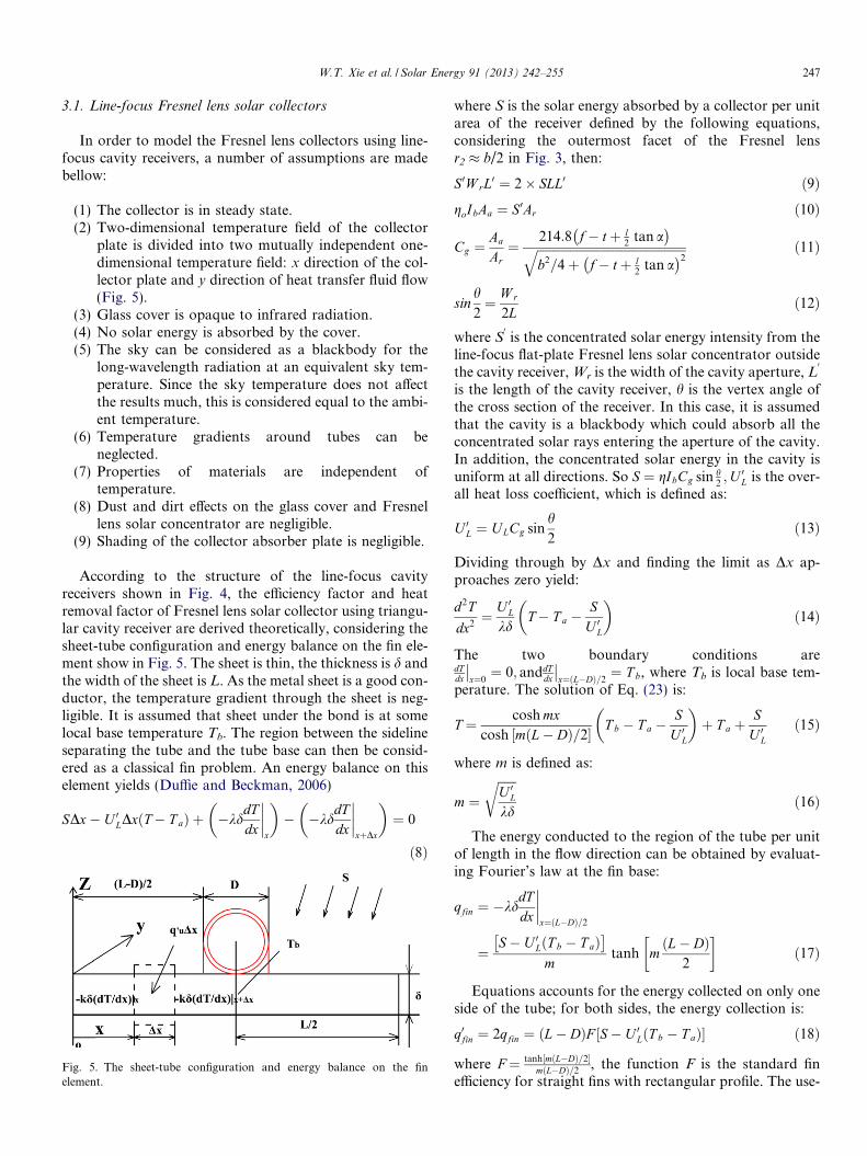
According to the structure of the line-focus cavityreceivers shown in Fig. 4, the efficiency factor and heatremoval factor of Fresnel lens solar collector using triangu-lar cavity receiver are derived theoretically, considering thesheet-tube configuration and energy balance on the fin ele-ment show in Fig. 5. The sheet is thin, the thickness is d andthe width of the sheet is L. As the metal sheet is a good con-ductor, the temperature gradient through the sheet is neg-ligible. It is assumed that sheet under the bond is at somelocal base temperature Tb. The region between the sidelineseparating the tube and the tube base can then be consid-ered as a classical fin problem. An energy balance on thiselement yields (Duffie and Beckman, 2006)
SDx� U 0LDxðT� T aÞ þ �kddTdx
����x
� �� �kd
dTdx
����xþDx
� �¼ 0
ð8Þ
Fig. 5. The sheet-tube configuration and energy balance on the finelement.
where S is the solar energy absorbed by a collector per unitarea of the receiver defined by the following equations,considering the outermost facet of the Fresnel lensr2 � b/2 in Fig. 3, then:
S0W rL0 ¼ 2� SLL0 ð9ÞgoIbAa ¼ S0Ar ð10Þ
Cg ¼Aa
Ar¼
214:8 f� tþ l2
tan a� �
ffiffiffiffiffiffiffiffiffiffiffiffiffiffiffiffiffiffiffiffiffiffiffiffiffiffiffiffiffiffiffiffiffiffiffiffiffiffiffiffiffiffiffiffiffiffiffiffiffib2=4þ f� tþ l
2tan a
� �2q ð11Þ
sinh2¼ W r
2Lð12Þ
where S0is the concentrated solar energy intensity from the
line-focus flat-plate Fresnel lens solar concentrator outsidethe cavity receiver, Wr is the width of the cavity aperture, L
0
is the length of the cavity receiver, h is the vertex angle ofthe cross section of the receiver. In this case, it is assumedthat the cavity is a blackbody which could absorb all theconcentrated solar rays entering the aperture of the cavity.In addition, the concentrated solar energy in the cavity isuniform at all directions. So S ¼ gIbCg sin h
2;U 0L is the over-
all heat loss coefficient, which is defined as:
U 0L ¼ ULCg sinh2
ð13Þ
Dividing through by Dx and finding the limit as Dx ap-proaches zero yield:
d2T
dx2¼ U 0L
kdT� T a �
SU 0L
� �ð14Þ
The two boundary conditions aredTdx
��x¼0¼ 0; anddT
dx
��x¼ðL�DÞ=2
¼ T b, where Tb is local base tem-perature. The solution of Eq. (23) is:
T ¼ cosh mxcosh mðL� DÞ=2½ � T b � T a �
SU 0L
� �þ T a þ
SU 0L
ð15Þ
where m is defined as:
m ¼ffiffiffiffiffiffiU 0Lkd
rð16Þ
The energy conducted to the region of the tube per unitof length in the flow direction can be obtained by evaluat-ing Fourier’s law at the fin base:
qfin ¼ �kddTdx
����x¼ðL�DÞ=2
¼S� U 0LðT b � T aÞ�
mtanh m
ðL� DÞ2
�ð17Þ
Equations accounts for the energy collected on only oneside of the tube; for both sides, the energy collection is:
q0fin ¼ 2qfin ¼ ðL� DÞF ½S� U 0LðT b � T aÞ� ð18Þ
where F ¼ tanh½mðL�DÞ=2�mðL�DÞ=2
, the function F is the standard finefficiency for straight fins with rectangular profile. The use-
248 W.T. Xie et al. / Solar Energy 91 (2013) 242–255
ful energy gain of the collector also includes the energy col-lected above the tube region. The energy gain is:
q0tube ¼pD2
S� U 0LðT b � T aÞ�
ð19Þ
The useful energy gain of the tube and fin per unit length inthe flow direction is the sum of Eqs. (27) and (28).
q0u ¼ q0fin þ q0tube
¼ ðL� DÞFþ pD2
�½S� U 0LðT b � T aÞ�Þ ð20Þ
Ultimately the useful gain from Eq. (29) must be trans-ferred to the fluid, which can be expressed in terms of thetwo resistances as:
q0u ¼T b � T f
1pDihfiþ 1
Cb
ð21Þ
where Cb is the bond conductance defined as:
Cb ¼kbbc
ð22Þ
where kb is the bond thermal conductivity, b is the bondwidth, c is the average bond thickness. Solving Eq. (30)for Tb, substituting it into Eq. (29) and solving the resultsfor the useful gain:
q0u ¼S� U 0LðT f � T aÞ
1ðL�DÞFþpD=2
þ 1pDihfiþ 1
Cb
� U 0L
¼ W rF 0½goIb � U LðT f � T aÞ� ð23Þ
where F0is collector efficiency factor, which is expressed as:
F 0 ¼ 1=W r
2Cgf½W r�2D sinðh=2Þ�FþpD sinðh=2Þg þ 1
pDihfiþ 1
Cb
� U L
ð24Þ
The useful gain per unit flow length as calculated fromEq. (32) is ultimately transferred to the fluid. The fluidenters the collector at temperature Ti, and increase in tem-perature until at the exit it is To. An energy balance on thefluid flowing through a single tube of length Dy as:
_mCpdT f
dy� W rF 0 goIb � U LðT f � T aÞ
� ¼ 0 ð25Þ
It is assumed that F0
and UL are independent of position,then the solution is:
T f � T a � goIb=UL
T i � T a � goIb=UL¼ exp �ULW ryF 0
_mCp
� �ð26Þ
If the receiver has a length of L0
in the flow direction thenthe outlet fluid temperature To is obtained by substitutingL0
for y in Eq. (35). The quantity WrL0
is the collector re-ceiver area Ar:
T o � T a � goIb=U L
T i � T a � goIb=UL¼ exp �U LW rL0F 0
_mCp
� �ð27Þ
The collector heat removal factor FR is defined as:
F R ¼_mCpðT o � T iÞ
Ar½S� U 0LðT fi � T aÞ�
¼_mCp 1� expð� W rL0ULF 0
_mCpÞ
h iW rL0UL
214:8 f�tþl2 tan að Þffiffiffiffiffiffiffiffiffiffiffiffiffiffiffiffiffiffiffiffiffiffiffiffiffiffiffiffiffi
b2=4þ f�tþl2 tan að Þ2
q sinðh=2Þð28Þ
then the actual useful energy gain is:
q0u ¼ W rF R214:8 f� tþ l
2tan a
� �ffiffiffiffiffiffiffiffiffiffiffiffiffiffiffiffiffiffiffiffiffiffiffiffiffiffiffiffiffiffiffiffiffiffiffiffiffiffiffiffiffiffiffiffiffiffiffiffiffib2=4þ f� tþ l
2tan a
� �2q sinðh=2Þ½goIb
� ULðT i � T aÞ� ð29Þ
For other kinds of line-focus Fresnel lens solar collectorusing cavity receivers, the same method is adopted toobtain the theoretical expressions. A summary of collectorefficiency factors and collector heat removal factors arepresented in Table 1.
3.2. Experimental validation
In order to compare the thermal performance of Fresnellens solar collector using line-focus cavity receivers, someuniform geometrical parameters of these cavities are speci-fied which are illustrated in Table 2. During the experi-ment, two PT-100 sensors of which the measurementprecision is ±0.1 �C are positioned to measure the temper-ature rise across the line-focus Fresnel lens solar collector.Another PT-100 sensor is positioned close to the concen-trator to measure the ambient temperature. The fluid flowrate is measured by a flow meter of which the relative erroris no more than 1%. The solar radiation is measured by apyranometer which can track the sun automatically andmeasure beam, diffused and total solar radiation respec-tively. Particularly, beam radiation is measured by a pyrhe-liometer designed specifically to measure the direct beamsolar irradiance with a field of view limited to 5�, and itis highly accurate and relative error is no more than 1%.All measuring transducers are connected to a data loggerKeithley 2700. Based on two standards ANSI/ASHRAE93-2010 and ASTM E905-1987(2007), the thermal perfor-mance of the line-focus Fresnel lens solar collector witheach cavity receiver is studied experimentally at differentinlet fluid temperature levels. Firstly, the experimental dataare obtained and recorded; secondly, the experimental dataare processed and the solar thermal efficiency fitting curvesand formulas are derived; thirdly, the overall heat loss coef-ficients are obtained; and finally, the experimental collectorfactors are determined from the gradient of each fitted for-mula divided by the overall heat loss coefficient. Moreover,the theoretical collector factors are obtained using theexperimentally obtained overall heat loss coefficient, struc-tural parameters of the cavities and the appropriate physi-cal parameters.
The theoretical and experimental values of the efficiencyfactors and the heat removal factors are presented in

Table 1A summary of the collector efficiency factors and collector heat removal factors of Fresnel lens solar collector using line-focus cavity receivers.*
Types of cavity receiver Collector efficiency factors Collector heat removal factors
Triangular cavity receiver F 0 ¼ 1=W r2
Cg f½W r�2D sinðh=2Þ�FþpD sinðh=2Þgþð1
pDi hfiþ 1
CbÞUL
F ¼ tanh½mðL�DÞ=2�mðL�DÞ=2 F R ¼ _mCp
W r L0ULCg sinðh=2Þ 1� exp � W rL0ULF 0
_mCp
� h i
Arc-shaped cavity receiver F 0 ¼ 1=W r
4p�2hCg f½ð2p�hÞW r�4D sinðh=2Þ�Fþ2pD sinðh=2Þgþ
1pDihfi
þ 1Cb
� UL
F R ¼ _mCp
W r L0UL2Cg sinðh=2Þ
2p�h
1� exp � W rL0ULF 0
_mCp
� h i
F ¼ tanhfm½ð2p�hÞW r�4D sinðh=2Þ�=½8 sinðh=2Þ�gm½ð2p�hÞW r�4D sinðh=2Þ�=½8 sinðh=2Þ�
Rectangular cavity receiver F 0 ¼ 1=W r
W rþ2lCg W r ½ðW r�2DÞF 1=2þðL�DÞF 2þpD=2�þ
1pDi hfi
þ 1Cb
� UL
F R ¼ _mCp
W r L0ULCg W rW rþ2L
1� exp � W rL0ULF 0
_mCp
� h i
F 1 ¼ tanh½mðW r�2DÞ=2�mðW r�2DÞ=2 ; F 2 ¼ tanh½mðL�DÞ�
mðL�DÞ
Semicircular cavity receiver F 0 ¼ 1=W r
p2Cg ½ðpW r�4DÞF =4þpD=2�þ
1pDi hfi
þ 1Cb
� UL
F R ¼ _mCp
W r L0UL2Cgp
1� exp � W rL0ULF 0
_mCp
� h i
F ¼ tanh½mðpW r�4DÞ=8�mðpW r�4DÞ=8
Positive trapezoidal cavity receiverF 0 ¼ 1=W r
2LþW r cosðh=2Þþ2L sinðh=2ÞCg W r cosðh=2Þ�B þ 1
pDihfiþ 1
Cb
� UL
B ¼ f½W r=2þ Ltgðh=2Þ � D�F 1 þ ½L= cosðh=2Þ � D�F 2 þ pD=2gF R ¼ _mCp
W r L0ULCg W r cosðh=2Þ
2LþW r cosðh=2Þþ2L sinðh=2Þ1� exp � W rL0ULF 0
_mCp
� h i
F 1 ¼ tanhfm½W r=2þLtgðh=2Þ�D�gm½W r=2þLtgðh=2Þ�D�
F 2 ¼ tanhfm½L= cosðh=2Þ�D�gm½L= cosðh=2Þ�D�
Reverse trapezoidal cavity receiverF 0 ¼ 1=W r
2LþW r cosðh=2Þ�2L sinðh=2ÞCg W r cosðh=2Þ�B þ 1
pDihfiþ 1
Cb
� UL
B ¼ f½W r=2� Ltgðh=2Þ � D�F 1 þ ½L= cosðh=2Þ � D�F 2 þ pD=2gF R ¼ _mCp
W r L0ULCg W r cosðh=2Þ
2LþW r cosðh=2Þ�2L sinðh=2Þ1� exp � W rL0ULF 0
_mCp
� h i
F 1 ¼ tanhfm½W r=2�Ltgðh=2Þ�D�gm½W r=2�Ltgðh=2Þ�D�
F 2 ¼ tanhfm½L= cosðh=2Þ�D�gm½L= cosðh=2Þ�D�
Hetero trapezoidal cavity receiver F 0 ¼ 1=W r
2½LþW r cosðh=2ÞþL sinðh=2Þ�Cg W r cosðh=2Þf½L= cosðh=2Þ�2D�FþpD=2gþ
1pDihfi
þ 1Cb
� UL
F R ¼ _mCp
W r L0ULCg W r cosðh=2Þ
2½LþW r cosðh=2ÞþL sinðh=2Þ�1� exp � W rL0ULF 0
_mCp
� h i
F ¼ tanh m L2 cosðh=2Þ � Dh in o
=m½ L2 cosðh=2Þ � D�
Convex cavity receiver F 0 ¼ 1=W rðpW rþ4L�2W r Þ
2Cg W rf½pW r�2D�F 1=4þ½L�ðW rþDÞ=2�F 2þpD=2gþð1
pDi hfiþ 1
CbÞUL
F R ¼ _mCp
W r L0UL2Cg W r
pW rþ4L�2W r
1� exp � W r L0ULF 0
_mCp
� h i
F 1 ¼ tanh½mðpW r�2DÞ=4�mðpW r�2DÞ=4 F 2 ¼ tanhfm½L�ðW rþDÞ=2�g
m½L�ðW rþDÞ=2�
* Where Cg ¼ AaAr¼ 214:8ðf�tþl
2 tan aÞffiffiffiffiffiffiffiffiffiffiffiffiffiffiffiffiffiffiffiffiffiffiffiffiffiffiffiffiffiffib2=4þðf�tþl
2 tan aÞ2p for line-focus Fresnel lens.
W.T. Xie et al. / Solar Energy 91 (2013) 242–255 249
Table 3. As can be seen, when the inlet fluid temperaturewas 90 �C, 150 �C and 180 �C, the triangular cavity recei-ver has the highest efficiency and heat removal factorscompared to any other kinds of line-focus cavity receivers.Fig. 6 illustrates the relationship between the inlet fluidtemperature and the collector factors of the line-focusFresnel lens solar collector using triangular cavity receiver.As seen, when the inlet fluid temperature increased from90 �C to 180 �C, the experimental heat removal factorsdecrease from 0.871 to 0.805, which may be attributed tothe considerable increase in the heat loss coefficient. Whenthe inlet fluid temperature increased from 180 �C to250 �C, the theoretical heat removal factors decrease from
0.813 to 0.723 which is because that the overall heat losscoefficient increased considerably while the heat convec-tion heat transfer coefficient increased not much. The heatremoval factors decrease significantly and bring a devia-tion between the theoretical and experimental resultswithin ±10% because of the higher overall heat loss coef-ficient which is more than 80 W/(m2 K) when the inletfluid temperature is higher than 200 �C. Consequently, itis predicted that when the inlet fluid temperature isbetween 150 �C and 180 �C, the line-focus Fresnel lenssolar collector using triangular cavity receiver has betterthermal performance for mid-temperature solar thermalconversion applications.
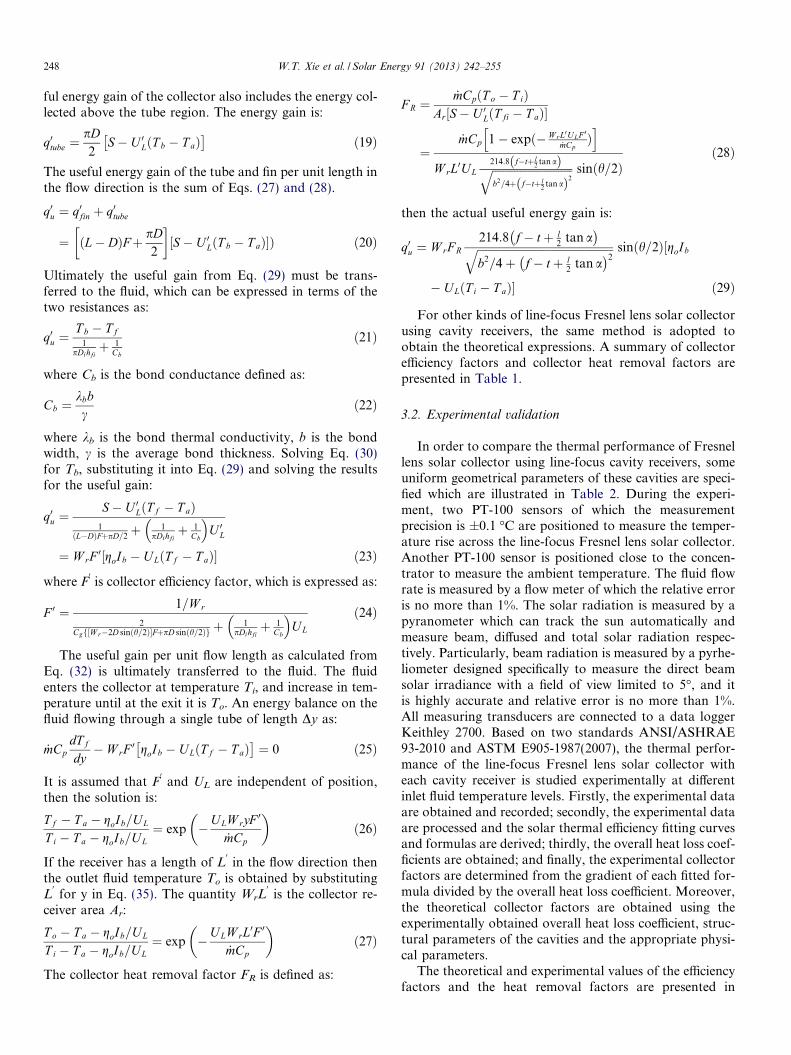
Table 2Specified uniform geometrical parameters of line-focus cavity receivers.
Triangularcavityreceiver
Arc-shapedcavityreceiver
Rectangularcavityreceiver
Semicircularcavityreceiver
Positivetrapezoidalcavity receiver
Reversetrapezoidalcavity receiver
Heterotrapezoidalcavity receiver
Convexcavityreceiver
Aperture width Wr (mm) 100 100 100 100 100 100 100 100Maximum depth L (mm) – – 100 – 100 100 100 100The vertex angle h (�) 60� – – – 60� 60� 60� –
250 W.T. Xie et al. / Solar Energy 91 (2013) 242–255
4. Results and discussion
As can be seen in Table 3, when the inlet fluid tempera-ture was 90 �C, the triangular cavity receiver has the bestthermal performance. The experimental efficiency factoris 0.870 and the experimental heat removal factor is 0.866when the inlet fluid temperature is 90 �C. However, whenthe inlet fluid temperature is 150 �C, the experimental effi-ciency factor is decreased to 0.843 and the experimentalheat removal factor is reduced to 0.824, respectively. Thearc-shaped cavity receiver has larger efficiency factor andheat removal factor than rectangular cavity receiver, semi-circular cavity receiver and convex cavity receiver but smal-ler than triangular cavity receiver when the inlet fluidtemperature is 90 �C. Moreover, when the inlet fluid tem-perature is 150 �C, the rectangular cavity receiver has lar-ger efficiency factor and heat removal factor than arc-shaped cavity receiver, semicircular cavity receiver andconvex cavity receiver. Nevertheless, the efficiency factorand heat removal factor of positive trapezoidal cavity recei-ver, reverse trapezoidal cavity receiver and hetero trapezoi-dal cavity receiver are small among the eight kinds of line-focus Fresnel solar collectors. In addition, the hetero trap-ezoidal cavity receiver has the smallest efficiency factor andheat removal factor because its structure results in a largerheat loss than the others. It can be thought that the trian-gular cavity receiver has the best thermal performance.
Furthermore, it is also found that the main factor whichinfluences the heat removal factor considerably is the overallheat loss coefficient. For example, considering the triangularcavity receiver; when the inlet fluid temperature is 90 �C, theoverall heat loss coefficient is 12 W/(m2 K); when the inletfluid temperature is 150 �C, the overall heat loss coefficientis 24 W/(m2 K); when the inlet fluid temperature is 180 �C,the overall heat loss coefficient is 50 W/(m2 K). The corre-sponding value of the experimental efficiency factor isdecreased to 0.811, whereas the experimental heat removalfactor is reduced to 0.805, respectively. The deviation betweenthe theoretical and experimental results is within ±5%.
The theoretical results are also shown in Table 3. As seen inTable 3, the efficiency factors and heat removal factors of line-focus Fresnel solar collector using triangular cavity receiverare higher than those of the other line-focus cavity receivers.
4.1. Simulation results and discussion
It can be seen from the theoretical expressions that themain factors, which have strong influence on the efficiency
factor and heat removal factor of Fresnel lens solar collec-tor using line-focus cavity receivers, are structural parame-ters of the cavities, overall heat loss coefficient, geometricalconcentration ratio, convection heat transfer coefficient ofreceiver tube and the properties of working fluid, the innerdiameter of the receiver tube, among others. Since the opti-mization processes for different cavity receivers based onthe two dimensionless parameters are similar, the line-focusFresnel lens solar collector using triangular cavity receiverare just analyzed and optimized here.
The effect of the width of the cavity aperture, the insidediameter of the receiver tube, the vertex angle of cross sec-tion through the symmetric axis of the receiver and the geo-metrical concentration ratio on the efficiency factors andthe heat removal factors are analyzed. The calculation con-ditions are taken the same as the above section. It isassumed that the other parameters are kept constant whenone specific parameter is varied.
Fig. 7 shows the relationship between the width of thecavity aperture and the collector factors of line-focus Fres-nel lens solar collector using triangular cavity receiver. Itcan be seen that, when the width of the cavity apertureincreases from 5 mm to 100 mm, the collector factors firstincrease and then decrease. Thus, there exists an optimumaperture width which is about 50 mm. The collector heatremoval factor decreases obviously because of larger widthof the cavity aperture which causes higher heat losses.
Fig. 8 illustrates the relationship between the insidediameter of the receiver tube and the collector factors ofline-focus Fresnel lens solar collector using triangular cav-ity receiver. As seen, when the inside diameter of the recei-ver tube increases from 8 mm to 27 mm, the collectorfactors first increase and then decrease. Increasing theinside diameter of the receiver tube could enhance the heattransfer to some extent and cause large heat loss. There-fore, there exists an optimum inside diameter which isabout 18 mm.
Fig. 9 shows the relationship between the vertex angle ofthe cross section of the receiver and the collector factors ofline-focus Fresnel lens using triangular cavity receiver.When the vertex angle of cross section of the cavity isincreased from 15� to 150�, the collector factors initiallyincrease rapidly. When the vertex angle is larger than 60�,little effect on thermal performance of the Fresnel lens solarcollector could be observed. This is because larger vertexangle with large aperture width leads to increased heat loss.Thus, there exists an optimum vertex angle which is about60�. The efficiency factor and heat removal factor decrease
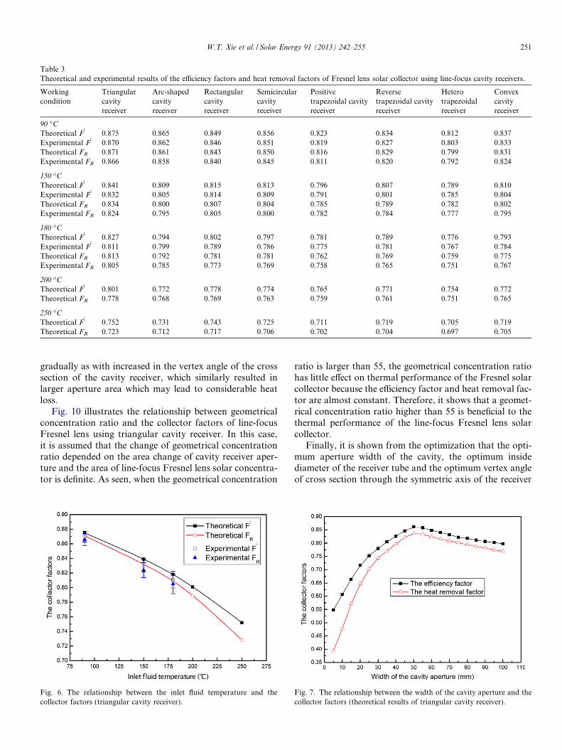
Table 3Theoretical and experimental results of the efficiency factors and heat removal factors of Fresnel lens solar collector using line-focus cavity receivers.
Workingcondition
Triangularcavityreceiver
Arc-shapedcavityreceiver
Rectangularcavityreceiver
Semicircularcavityreceiver
Positivetrapezoidal cavityreceiver
Reversetrapezoidal cavityreceiver
Heterotrapezoidalreceiver
Convexcavityreceiver
90 �C
Theoretical F0
0.875 0.865 0.849 0.856 0.823 0.834 0.812 0.837Experimental F
00.870 0.862 0.846 0.851 0.819 0.827 0.803 0.833
Theoretical FR 0.871 0.861 0.843 0.850 0.816 0.829 0.799 0.831Experimental FR 0.866 0.858 0.840 0.845 0.811 0.820 0.792 0.824
150 �C
Theoretical F0
0.841 0.809 0.815 0.813 0.796 0.807 0.789 0.810Experimental F
00.832 0.805 0.814 0.809 0.791 0.801 0.785 0.804
Theoretical FR 0.834 0.800 0.807 0.804 0.785 0.789 0.782 0.802Experimental FR 0.824 0.795 0.805 0.800 0.782 0.784 0.777 0.795
180 �C
Theoretical F0
0.827 0.794 0.802 0.797 0.781 0.789 0.776 0.793Experimental F
00.811 0.799 0.789 0.786 0.775 0.781 0.767 0.784
Theoretical FR 0.813 0.792 0.781 0.781 0.762 0.769 0.759 0.775Experimental FR 0.805 0.785 0.773 0.769 0.758 0.765 0.751 0.767
200 �C
Theoretical F0
0.801 0.772 0.778 0.774 0.765 0.771 0.754 0.772Theoretical FR 0.778 0.768 0.769 0.763 0.759 0.761 0.751 0.765
250 �C
Theoretical F0
0.752 0.731 0.743 0.725 0.711 0.719 0.705 0.719Theoretical FR 0.723 0.712 0.717 0.706 0.702 0.704 0.697 0.705
W.T. Xie et al. / Solar Energy 91 (2013) 242–255 251
gradually as with increased in the vertex angle of the crosssection of the cavity receiver, which similarly resulted inlarger aperture area which may lead to considerable heatloss.
Fig. 10 illustrates the relationship between geometricalconcentration ratio and the collector factors of line-focusFresnel lens using triangular cavity receiver. In this case,it is assumed that the change of geometrical concentrationratio depended on the area change of cavity receiver aper-ture and the area of line-focus Fresnel lens solar concentra-tor is definite. As seen, when the geometrical concentration
Fig. 6. The relationship between the inlet fluid temperature and thecollector factors (triangular cavity receiver).
ratio is larger than 55, the geometrical concentration ratiohas little effect on thermal performance of the Fresnel solarcollector because the efficiency factor and heat removal fac-tor are almost constant. Therefore, it shows that a geomet-rical concentration ratio higher than 55 is beneficial to thethermal performance of the line-focus Fresnel lens solarcollector.
Finally, it is shown from the optimization that the opti-mum aperture width of the cavity, the optimum insidediameter of the receiver tube and the optimum vertex angleof cross section through the symmetric axis of the receiver
Fig. 7. The relationship between the width of the cavity aperture and thecollector factors (theoretical results of triangular cavity receiver).

Fig. 8. The relationship between the inside diameter of the receiver tubeand the collector factors (theoretical results of triangular cavity receiver).
Fig. 9. The relationship between the vertex angle of cross section and thecollector factors (theoretical results of triangular cavity receiver).
Fig. 10. The relationship between geometrical concentration ratio and thecollector factors (theoretical results of triangular cavity receiver).
252 W.T. Xie et al. / Solar Energy 91 (2013) 242–255
are 50 mm, 18 mm, 60�, respectively. Moreover, it is sug-gested that the geometrical concentration ratio is morethan 55 for better thermal performance of the line-focusFresnel lens solar collector using triangular cavity receiver.
4.2. Optimization analysis
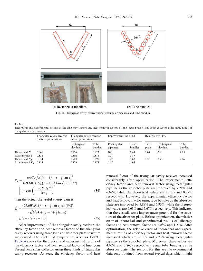
Some improvements are necessary. These improvementsinclude: giving up the tube-plate binding structure andusing rectangular pipeline as the absorb plate directly inthe cavity receiver which is shown in Fig. 11; the aperturewidth is set as the optimum aperture width which is about50 mm; the equivalent diameter of each cavity receiver sideis set as the optimum inside diameter which is about18 mm; the vertex angle is set as 60�, increasing the massflow rate for higher convection heat transfer coefficientinside the rectangular pipelines.
For the optimized triangular cavity receiver using rect-angular pipeline as the absorber plate, using the sameassumptions adopted in Section 3.1, the collector efficiencyfactor F
0, which is expressed as:
F 0 ¼ 1=W rffiffiffiffiffiffiffiffiffiffiffiffiffiffiffiffiffiffiffiffiffiffiffiffiffiffiffiffiffib2=4þ f�tþl
2 tan að Þ2q
107:4 f�tþl2 tan að Þ sinðh=2Þ
þ d0
k þ 1hfi
� UL
ð30Þ
where d0
is the thickness of the rectangular pipeline. Thecollector heat removal factor FR is:
F R ¼_mCp
ffiffiffiffiffiffiffiffiffiffiffiffiffiffiffiffiffiffiffiffiffiffiffiffiffiffiffiffiffiffiffiffiffiffiffiffiffiffiffiffiffiffiffiffiffiffiffiffiffib2=4þ f� tþ l
2tan a
� �2q
214:8W rL0UL f� tþ l2
tan a� �
sinðh=2Þ
1� exp �W rL0ULF 0
_mCp
� � �ð31Þ
then the actual the useful energy gain is:
q0u ¼ W rF R214:8 f� tþ l
2tan a
� �ffiffiffiffiffiffiffiffiffiffiffiffiffiffiffiffiffiffiffiffiffiffiffiffiffiffiffiffiffiffiffiffiffiffiffiffiffiffiffiffiffiffiffiffiffiffiffiffiffib2=4þ f� tþ l
2tan a
� �2q sinðh=2Þ½goIb
� ULðT i � T aÞ� ð32Þ
In the actual experiment, it is found that the rectangularpipeline is easily deformed when the system operation pres-sure is more than 3 bar using synthesis oil as heat transferfluid (HTF) which might lead to poor performance. Conse-quently, the rectangular pipelines are replaced by tube bun-dles which are also shown in Fig. 11. Finally, the collectorefficiency factor F
0, which is expressed as:
F 0 ¼ 1ffiffiffiffiffiffiffiffiffiffiffiffiffiffiffiffiffiffiffiffiffiffiffiffiffiffiffiffiffib2=4þ f�tþl
2 tan að Þ2q
107:4 f�tþl2 tan að Þ þ
12pk lnðD=DiÞ þ
1pDihfi
h iU L2D sinðh=2Þ
ð33Þ
the collector heat removal factor FR is:
a Rectangular pipelines b Tube bundles ( ) ( )
Fig. 11. Triangular cavity receiver using rectangular pipelines and tube bundles.
Table 4Theoretical and experimental results of the efficiency factors and heat removal factors of line-focus Fresnel lens solar collector using three kinds oftriangular cavity receivers.
Triangular cavity receiver(before optimization)
Triangular cavity receiver(after optimization)
Improvement ratio (%) Relative error (%)
Rectangularpipelines
Tubebundles
Rectangularpipelines
Tubebundles
Tubeplate
Rectangularpipelines
Tubebundles
Theoretical F0
0.841 0.926 0.922 10.1 9.63 1.08 3.81 4.65Experimental F
00.832 0.892 0.881 7.21 5.89
Theoretical FR 0.834 0.903 0.898 8.27 7.67 1.21 2.73 2.86Experimental FR 0.824 0.879 0.873 6.67 5.95
W.T. Xie et al. / Solar Energy 91 (2013) 242–255 253
F R ¼p _mCp
ffiffiffiffiffiffiffiffiffiffiffiffiffiffiffiffiffiffiffiffiffiffiffiffiffiffiffiffiffiffiffiffiffiffiffiffiffiffiffiffiffiffiffiffiffiffiffiffiffib2=4þ f� tþ l
2tan a
� �2q
429:6W rL0UL f� tþ l2
tan a� �
sinðh=2Þ
1� exp �W rL0U LF 0
_mCp
� � �ð34Þ
then the actual the useful energy gain is:
q0u ¼429:6W rF R f� tþ l
2tan a
� �sinðh=2Þ
pffiffiffiffiffiffiffiffiffiffiffiffiffiffiffiffiffiffiffiffiffiffiffiffiffiffiffiffiffiffiffiffiffiffiffiffiffiffiffiffiffiffiffiffiffiffiffiffiffib2=4þ f� tþ l
2tan a
� �2q
½goIb � ULðT i � T aÞ� ð35Þ
After improvement of the triangular cavity receiver, theefficiency factor and heat removal factor of the triangularcavity receiver using three kinds of absorber plate structureare derived. The inlet fluid temperature is set as 150 �C.Table 4 shows the theoretical and experimental results ofthe efficiency factor and heat removal factor of line-focusFresnel lens solar collector using three kinds of triangularcavity receivers. As seen, the efficiency factor and heat
removal factor of the triangular cavity receiver increasedconsiderably after optimization. The experimental effi-ciency factor and heat removal factor using rectangularpipeline as the absorber plate are improved by 7.21% and6.67%, while the theoretical values are 10.1% and 8.27%respectively. However, the experimental efficiency factorand heat removal factor using tube bundles as the absorberplate are improved by 5.89% and 5.95%, while the theoret-ical values are 9.63% and 7.67% respectively. This indicatesthat there is still some improvement potential for the struc-ture of the absorber plate. Before optimization, the relativeerror of theoretical and experimental results of efficiencyfactor and heat removal factor are 1.08% and 1.21%. Afteroptimization, the relative error of theoretical and experi-mental results of efficiency factor and heat removal factorincreased which are 3.81% and 2.73% using rectangularpipeline as the absorber plate. Moreover, these values are4.65% and 2.86% respectively using tube bundles as theabsorber plate. The reasons for this are the experimentaldata only obtained from several typical days which might

254 W.T. Xie et al. / Solar Energy 91 (2013) 242–255
cause fluctuation of fitting curve; higher temperature couldcause poor performance of insulation materials; poor airtightness of glass cover over the cavity receiver; low accu-racy of the tracking system; wide fluctuation range of over-all heat loss coefficient, etc. In addition, the deviationbetween the theoretical and experimental results of effi-ciency factors and heat removal factors is within 5%. Con-sequently, it is suggested that the line-focus Fresnel lenssolar collector using rectangular pipelines triangular cavityreceiver design when the system operation pressure is notvery high (about 2 bar using synthesis oil as HTF), whiletube bundles triangular cavity receiver design should beadopted when the system operation pressure is higher(more than 3 bar using synthesis oil as HTF).
5. Conclusions
In this paper, the thermal performance of a line-focusFresnel lens solar collector using different cavity receivershas been investigated. Analysis on eight different types ofline-focus cavity receivers is made. The collector efficiencyfactors and collector heat removal factors of these receiversand two optimized line-focus cavity receivers are derivedand compared theoretically and experimentally. The mainconclusions can be drawn:
(1) The theoretical collector efficiency factors and collec-tor heat removal factors for concentrating solar col-lector using cavity receivers can be used to evaluatethe thermal performance of concentrating solar col-lectors directly. It is convenient to design the optimalparameters of different cavities and to predict theirperformance under different temperature levels withthese formulas.
(2) The analysis on the collector efficiency factors and thecollector heat removal factors indicate that the trian-gular cavity receiver has the best thermal perfor-mance. The highest experimental heat removalfactor is about 0.805 when the operation temperatureis 180 �C. An optimum width of cavity aperture isabout 50 mm, an optimum inside diameter is about18 mm, an optimum vertex angle is about 60�, anda geometrical concentration ratio of more than 55,are recommended, for good thermal performance ofa line-focus Fresnel lens solar collector using triangu-lar cavity receiver.
(3) It is found that the theoretical results agree with thetest results well that the relative error of efficiency fac-tors and heat removal factors between the theoreticaland experimental results is within 5%. When the inlettemperature is more than 200 �C, the deviation iswithin 10% because of the higher overall heat losscoefficient which is more than 80 W/(m2 K).
(4) When the system operation pressure is not very high(about 2 bar using synthesis oil as HTF), the line-focus Fresnel lens solar collector using optimizedrectangular pipelines triangular cavity receiver design
can be adopted. However, it is suggested that the line-focus Fresnel lens solar collector using optimizedtube bundles triangular cavity receiver design shouldbe adopted when the system operation pressure ishigher (more than 3 bar using synthesis oil as HTF).
Acknowledgements
This work was supported by the National Natural Sci-ence Foundation of China under the Contract No.51276112, the key scientific and technological project ofScience and Technology Commission of Shanghai Munici-pality under the Contract No. 10dz1203402, and the Grad-uates’ Creativity Fund of Shanghai Jiao Tong Universityunder the Contract No. TS0220702002.
References
Chemisana, D., Rosell, J.I., 2011. Design and optical performance of anonimaging Fresnel transmissive for building integration applications.Energy Conversion and Management 52 (10), 3241–3248.
Chemisana, D., Ibanez, M., Barrau, J., 2009. Comparison of Fresnelconcentrators for building integrated photovoltaics. Energy Conver-sion and Management 50 (4), 1079–1084.
Duffie, J.A., Beckman, W.A., 2006. Solar Engineering of Thermal Process,third ed. John Wiley & Sons, New Jersey, USA.
Eisenmann, W., Vajen, K., Ackermann, H., 2004. On the correlationsbetween collector efficiency factor and material content of parallel flowflat-plate solar collectors. Solar Energy 76 (4), 381–387.
Ezekwe, C.I., 1990. Thermal performance of heat pipe solar energysystems. Solar and Wind Technology 7 (4), 349–354.
He, Z.N., 2009. Solar Thermal Utilization. USTC Press, Hefei, China (inChinese).
Hellstrom, B., 2004. Derivation of efficiency factors for uneven irradiationon a fin absorber. Solar Energy 77 (3), 261–267.
Jirka, V., Kuceravy, K., Maly, M., Pech, F., Pokorny, J., 1999. Energyflow in a greenhouse equipped with glass raster lenses. RenewableEnergy 16 (1–4), 660–664.
Khalifa, A.J.N., 1998. Forced versus natural circulation solar waterheaters: a comparative performance study. Renewable Energy 14 (1–4), 77–82.
Korecko, J., Jirka, V., Sourek, B., Cerveny, J., 2010. Module greenhousewith high efficiency of transformation of solar energy, utilizingactive and passive glass optical rasters. Solar Energy 84 (10), 1794–1808.
Kudish, A.I., Evseev, E.G., Walter, G., Leukefeld, T., 2002. Simulationstudy of a solar collector with a selectively coated polymeric doublewalled absorber plate. Energy Conversion and Management 43 (5),651–671.
Kuo, C.F.J., Feriyonika, Huang, C.C., Kuo, Y.L., 2012. Analysis ofprocessing parameters in fabrication of Fresnel lens solar collector.Energy Conversion and Management 57 (1), 33–41.
Leutz, R., Suzuki, A., 2001. Nonimaging Fresnel Lenses: Design andPerformance of Solar Concentrators. Springer Verlag, Heidelberg.
Liu, J.M., 2010. Solar Energy Utilization: Principle, Technology, Engi-neering. Publishing House of Electronics Industry, Beijing, China (inChinese).
Ma, L.D., Lu, Z., Zhang, J.L., Liang, R.B., 2010. Thermal performanceanalysis of the glass evacuated tube solar collector with U-tube.Building and Environment 45 (9), 1959–1967.
Moummi, N., Youcef-Ali, S., Moummi, A., Desmons, J.Y., 2004. Energyanalysis of a solar air collector with rows of fins. Renewable Energy 29(13), 2053–2064.
W.T. Xie et al. / Solar Energy 91 (2013) 242–255 255
Norton, B., Prapas, D.E., Eames, P.C., Probert, S.D., 1989. Measuredperformances of curved inverted-Vee, absorber compound parabolicconcentrating solar-energy collectors. Solar Energy 43 (5), 267–279.
Rabl, A., O’Gallagher, J., Winston, R., 1980. Design and test of non-evacuated solar collectors with compound parabolic concentrators.Solar Energy 25 (4), 335–351.
Shariah, A.M., Rousan, A., Rousan, K.K., Ahmad, A.A., 1999.Effect of thermal conductivity of absorber plate on the perfor-mance of a solar water heater. Applied Thermal Engineering 19(7), 733–741.
Siddiqui, M.A., 1997. Heat transfer and fluid flow studies in the collectortubes of a closed-loop natural circulation solar water heater. EnergyConversion and Management 38 (8), 799–812.
Sonneveld, P.J., Swinkels, G.L.A.M., van Tuijl, B.A.J., Janssen, H.J.J.,Campen, J., Bot, G.P.A., 2011. Performance of a concentratedphotovoltaic energy system with static linear Fresnel lenses. SolarEnergy 85 (3), 432–442.
Tripanagnostopoulos, Y., Siabekou, Ch., Tonui, J.K., 2007. TheFresnel lens concept for solar control of buildings. Solar Energy81, 661–675.
Tsilingiris, P.T., 2000. Heat transfer analysis of low thermal conductivitysolar energy absorbers. Applied Thermal Engineering 20 (14), 1297–1314.
Tsilingiris, P.T., 2002. Back absorbing parallel plate polymer absorbers insolar collector design. Energy Conversion and Management 43 (1),135–150.
Valmiki, M.M., Li, P.W., Heyer, J., Morgan, M., Albinali, A., Aihamidi,K., Wagoner, J., 2011. A novel application of a Fresnel lens for a solarstove and solar heating. Renewable Energy 36 (5), 1614–1620.
Xie, W.T., Dai, Y.J., Wang, R.Z., 2011a. Numerical and experimentalanalysis of a point focus solar collector using high concentrationimaging PMMA Fresnel lens. Energy Conversion and Management 52(6), 2417–2426.
Xie, W.T., Dai, Y.J., Wang, R.Z., Sumathy, K., 2011b. Concentratedsolar energy applications using Fresnel lenses: a review. Renewableand Sustainable Energy Reviews 15 (6), 2588–2606.
Zhai, H., Dai, Y.J., Wu, J.Y., Wang, R.Z., Zhang, L.Y., 2010.Experimental investigation and analysis on a concentrating solarcollector using linear Fresnel lens. Energy Conversion and Manage-ment 51 (1), 48–55.