1 relevant standards for substation plants
TRANSCRIPT
8/3/2019 1 Relevant Standards for Substation Plants
http://slidepdf.com/reader/full/1-relevant-standards-for-substation-plants 1/223
RELEVANT ELECTRICAL STANDARDS
Issue 1
9th
January 2006

8/3/2019 1 Relevant Standards for Substation Plants
http://slidepdf.com/reader/full/1-relevant-standards-for-substation-plants 2/223
NGET Relevant Electrical StandardsIssue 1.0 – 9
thJanuary 2006
Uncontrolled When Printed
© National Grid 2005
“No part of this publication may be reproduced, stored in aretrieval system, or transmitted in any form or by any meanselectronic, mechanical, photocopying, recording or otherwise,without the written permission of National Grid’s obtained fromthe issuing location.
The contents of National Grid engineering documents arebased on the needs of National Grid and the conditions under which it operates. It should not therefore be assumed that thespecifications and requirements stated therein necessarily meetthe particular circumstances and requirements of other organisations. The principles set out in this document are for information only and therefore National Grid is not liable tocustomers / suppliers for any loss or damage resulting fromreliance on the contents. It is the responsibility of such externalorganisations to check that the document is the latest versionand is appropriate for their purposes.”
(National Grid Legal Services. November 1999)
Registered Office Registered in1-3 Strand England and WalesLondon No. 2366977WC2N 5EH
Published by:
National GridWarwick Technology ParkGallows HillWarwickCV34 6DA
This document has been prepared by the following User Group:
Tony Westmorland Asset PolicyJohn Hyde Asset Policy
8/3/2019 1 Relevant Standards for Substation Plants
http://slidepdf.com/reader/full/1-relevant-standards-for-substation-plants 3/223
NGET Relevant Electrical Standards
Issue 1.0 – 9th
January 2006
Uncontrolled When Printed Page i
CONTENTS
PART 1 – INTRODUCTION 1
PART 2 – ADMINISTRATION 3
PART 3 - GENERAL REQUIREMENTS 5
1 SECTION 1 - TYPE REGISTRATION........................................................................................... 6
2 SECTION 2 - MANAGEMENT OF RISE OF EARTH POTENTIAL AT NEW ANDREFURBISHED TOWERS............................................................................................................ 7
2.1 PURPOSE AND SCOPE.......................................................................................... 7 2.2 REQUIREMENTS..................................................................................................... 7
3 SECTION 3 – BACK-UP PROTECTION GRADING ACROSS NGET’S AND OTHERNETWORK OPERATOR INTERFACES....................................................................................... 8
3.1 PURPOSE AND SCOPE.......................................................................................... 8 3.2 SUPERGRID/132 KV AUTO-TRANSFORMERS..................................................... 8
3.3 SUPERGRID/66 KV OR LOWER VOLTAGE DOUBLE-WOUNDTRANSFORMERS.................................................................................................... 9
3.4 GRADING WITH NGET OWNED 132 KV OR LOWER VOLTAGE BUS SECTIONSAND COUPLERS ................................................................................................... 10
PART 4 - SPECIFIC REQUIREMENTS 11
4 SECTION 1 - RATINGS AND GENERAL REQUIREMENTS FOR PLANT, EQUIPMENT AND
APPARATUS FOR THE TRANSMISSION SYSTEM IN ENGLAND AND WALES ANDCONNECTION POINTS TO IT ................................................................................................... 11
4.1 SCOPE ................................................................................................................... 11 4.2 REFERENCES AND DEFINITIONS....................................................................... 11 4.3 SERVICE (ENVIRONMENTAL) CONDITIONS...................................................... 14 4.4 SYSTEM REQUIREMENTS................................................................................... 16 4.5 RATING REQUIREMENTS .................................................................................... 18 4.6 GENERAL REQUIREMENTS ................................................................................ 20 4.7 MANUALS, SUPPORT DOCUMENTATION AND DRAWINGS ............................ 21 4.8 GUIDANCE NOTES - HEAVY WETTING TEST SPECIFICATION ....................... 22
5 SECTION 2 - SUBSTATIONS..................................................................................................... 24 5.1 TECHNICAL REQUIREMENTS FOR SUBSTATIONS CONNECTED TO THE
TRANSMISSION SYSTEM IN ENGLAND AND WALES....................................... 24 5.2 GENERAL REQUIREMENTS (INCLUDING HEALTH & SAFETY) ....................... 24 5.3 STATUTORY REQUIREMENTS............................................................................ 24 5.4 ENVIRONMENTAL IMPACT.................................................................................. 24 5.5 DESIGN LIFE OF INSTALLATION......................................................................... 24 5.6 OPERATIONAL ACCESS ...................................................................................... 24 5.7 REQUIREMENTS FOR MAINTENANCE............................................................... 25 5.8 INTERLOCKING..................................................................................................... 25 5.9 CURRENT TRANSFORMERS............................................................................... 25
5.10 SWITCHGEAR SECONDARY ISOLATION........................................................... 25 5.11 VOLTAGE TRANSFORMER SECONDART ISOLATIOn ...................................... 25

8/3/2019 1 Relevant Standards for Substation Plants
http://slidepdf.com/reader/full/1-relevant-standards-for-substation-plants 4/223
NGET Relevant Electrical Standards
Issue 1.0 – 9th
January 2006
Uncontrolled When Printed Page ii
5.12 EARTHING ............................................................................................................. 25 5.13 PLANT AND EQUIPMENT IDENTIFICATION ....................................................... 26 5.14 LIGHT CURRENT EQUIPMENT............................................................................ 26
5.15 SUBSTATION AUXILIARY CABLING.................................................................... 27 5.16 SEGREGATION OF EQUIPMENT OWNED BY NGET & OTHER USERS .......... 27
5.17 CRANES & LIFTING EQUIPMENT........................................................................ 28 5.18 FACILITIES............................................................................................................. 28 5.19 SITE SECURITY..................................................................................................... 28 5.20 FIRE PROTECTION............................................................................................... 28 5.21 GENERAL REQUIREMENTS SPECIFIC TO AIS SUBSTATIONS ....................... 29 5.22 GENERAL REQUIREMENTS SPECIFIC TO GIS SUBSTATIONS....................... 33 5.23 PERFORMANCE REQUIREMENTS FOR ALL SWITCHGEAR............................ 34 5.24 ROUTINE TESTS AT SITE .................................................................................... 34 5.25 REFERENCES ....................................................................................................... 34 5.26 GUIDANCE NOTE - CURRENT TRANSFORMER (CT) ACCOMMODATION...... 36 5.27 GUIDANCE NOTE - LOCATION OF CURRENT TRANSFORMERS ASSOCIATED
WITH 420, 300 AND 145 kV CIRCUIT BREAKERS .............................................. 39 6 SECTION 3 - SWITCHGEAR...................................................................................................... 40
6.1 TECHNICAL REQUIREMENTS FOR SWITCHGEAR CONNECTED TO THETRANSMISSION SYSTEM IN ENGLAND AND WALES....................................... 40
6.2 GENERAL REQUIREMENTS ................................................................................ 40 6.3 PERFORMANCE REQUIREMENTS...................................................................... 41 6.4 TEST REQUIREMENTS FOR SWITCHGEAR ...................................................... 42 6.5 REFERENCES ....................................................................................................... 44
7 SECTION 4 - EARTHING ........................................................................................................... 45
7.1 PURPOSE AND SCOPE........................................................................................ 45 7.2 GENERAL REQUIREMENTS ................................................................................ 45 7.3 PERFORMANCE REQUIREMENTS...................................................................... 53
7.4 DESIGN INFORMATION........................................................................................ 53 7.5 TEST REQUIREMENTS......................................................................................... 54 7.6 ACCEPTANCE PROCEDURE............................................................................... 54 7.7 REFERENCES ....................................................................................................... 55 7.8 DEFINITIONS......................................................................................................... 55 7.9 GUIDANCE NOTE - MEASUREMENT METHODS ............................................... 57 7.10 GUIDANCE NOTE - FIGURES .............................................................................. 58
8 SECTION 5 - SUBSTATION AUXILIARY SUPPLIES ................................................................ 63
8.1 PURPOSE AND SCOPE........................................................................................ 63 8.2 GENERAL REQUIREMENTS ................................................................................ 63 8.3 PERFORMANCE REQUIREMENTS...................................................................... 64
8.4 REFERENCES ....................................................................................................... 65
9 SECTION 6 - ANCILLARY LIGHT CURRENT EQUIPMENT..................................................... 66
9.1 PURPOSE AND SCOPE........................................................................................ 66 9.2 GENERAL REQUIREMENTS ................................................................................ 66 9.3 PERFORMANCE REQUIREMENTS...................................................................... 75 9.4 TEST REQUIREMENTS......................................................................................... 76 9.5 TECHNICAL DATA................................................................................................. 76
9.6 REFERENCES ....................................................................................................... 76 10 SECTION 7 - SUBSTATION INTERLOCKING SCHEMES........................................................ 78
8/3/2019 1 Relevant Standards for Substation Plants
http://slidepdf.com/reader/full/1-relevant-standards-for-substation-plants 5/223
NGET Relevant Electrical Standards
Issue 1.0 – 9th
January 2006
Uncontrolled When Printed Page iii
10.1 PURPOSE AND SCOPE........................................................................................ 78 10.2 GENERAL REQUIREMENTS ................................................................................ 78
11 SECTION 8 – SYNCRONISING ................................................................................................. 80
11.1 SCOPE ................................................................................................................... 80
11.2 DEFINITIONS......................................................................................................... 80 11.3 GENERAL REQUIREMENTS ................................................................................ 81 11.4 FUNCTIONAL INTERFACES................................................................................. 84 11.5 SETTINGS.............................................................................................................. 85 11.6 PERFORMANCE REQUIREMENTS...................................................................... 86
12 SECTION 9 - CIRCUIT BREAKERS........................................................................................... 87
12.1 PURPOSE AND SCOPE........................................................................................ 87
12.2 GENERAL REQUIREMENTS ................................................................................ 87 12.3 PERFORMANCE REQUIREMENTS...................................................................... 91 12.4 TEST REQUIREMENTS......................................................................................... 92
12.5 DEFINITIONS......................................................................................................... 94 12.6 REFERENCES ....................................................................................................... 94 12.7 GUIDANCE NOTES - OPENING AND CLOSING RELEASE LOGIC DIAGRAMS94
13 SECTION 10 - DISCONNECTORS AND EARTHING SWITCHES............................................ 99
13.1 PURPOSE AND SCOPE........................................................................................ 99
13.2 RATINGS AND PERFORMANCE REQUIREMENTS............................................ 99 13.3 GENERAL REQUIREMENTS FOR DISCONNECTORS AND EARTH SWITCHES
.............................................................................................................................. 100 13.4 OPERATING MECHANISMS, ANCILLARY EQUIPMENT AND THEIR
ENCLOSURES..................................................................................................... 101 13.6 REFERENCES ..................................................................................................... 103
13.7 GUIDANCE NOTE - AUXILIARY SWITCH CONTACT POSITIONS IN RELATIONTO THE DISCONNECTOR POSITION................................................................ 104
14 SECTION 11 - CURRENT TRANSFORMERS FOR PROTECTION AND GENERAL USE .... 105
14.1 PURPOSE AND SCOPE...................................................................................... 105 14.2 GENERAL REQUIREMENTS .............................................................................. 105
14.3 PERFORMANCE REQUIREMENTS.................................................................... 106 14.4 TESTING REQUIREMENTS ................................................................................ 107 14.5 SCHEDULES........................................................................................................ 110
14.6 REFERENCES ..................................................................................................... 112 14.7 GUIDANCE NOTE - MULTICHOPPED IMPULSE TYPE TEST SPECIFICATION
.............................................................................................................................. 113 14.8 GUIDANCE NOTE - ADDITIONAL REQUIREMENTS FOR PROTECTION CLASS
PX TRANSFORMERS.......................................................................................... 114
15 SECTION 12 - BUSHINGS ....................................................................................................... 120
15.1 PURPOSE AND SCOPE...................................................................................... 120 15.2 GENERAL REQUIREMENTS .............................................................................. 120
15.3 PERFORMANCE REQUIREMENTS.................................................................... 120 15.4 TYPE TEST REQUIREMENTS............................................................................ 120
15.5 ADDITIONAL TYPE TEST FOR BUSHINGS OF THE CAPACITIVELY GRADEDTYPE..................................................................................................................... 120
15.6 ROUTINE TEST REQUIREMENTS..................................................................... 121
15.7 REFERENCES ..................................................................................................... 121 16 SECTION 13 - SOLID CORE POST INSULATOR FOR SUBSTATIONS................................ 122
8/3/2019 1 Relevant Standards for Substation Plants
http://slidepdf.com/reader/full/1-relevant-standards-for-substation-plants 6/223
NGET Relevant Electrical Standards
Issue 1.0 – 9th
January 2006
Uncontrolled When Printed Page iv
16.1 PURPOSE AND SCOPE...................................................................................... 122 16.2 RATINGS AND PERFORMANCE REQUIREMENTS.......................................... 122 16.3 TEST REQUIREMENTS....................................................................................... 122
16.4 REFERENCES ..................................................................................................... 123
17 SECTION 14 - BUSBAR PROTECTION................................................................................... 124
17.1 SCOPE ................................................................................................................. 124 17.2 REFERENCES ..................................................................................................... 124 17.3 FUNCTIONAL REQUIREMENTS......................................................................... 124 17.4 PERFORMANCE REQUIREMENTS.................................................................... 127 17.5 TESTING .............................................................................................................. 128
18 SECTION 15 - CIRCUIT BREAKER FAIL PROTECTION........................................................ 132
18.1 SCOPE ................................................................................................................. 132 18.2 REFERENCES ..................................................................................................... 132 18.3 FUNCTIONAL REQUIREMENTS......................................................................... 132
18.4 PERFORMANCE REQUIREMENTS.................................................................... 134 18.5 TEST REQUIREMENTS....................................................................................... 135
19 SECTION 16 - ENVIRONMENTAL AND TEST REQUIREMENTS FOR ELECTRONICEQUIPMENT............................................................................................................................. 142
19.1 SCOPE ................................................................................................................. 142
19.2 INTRODUCTION .................................................................................................. 142 19.3 DEFINITIONS....................................................................................................... 142 19.4 REFERENCES ..................................................................................................... 142
19.5 IEC STANDARDS................................................................................................. 143 19.6 GENERAL REQUIREMENTS .............................................................................. 144 19.7 GENERAL TEST REQUIREMENTS.................................................................... 146
19.8 ELECTRICAL ENVIRONMENTAL TESTS........................................................... 152 19.9 ATMOSPHERIC ENVIRONMENTAL TESTS....................................................... 166 19.10 MECHANICAL TESTS.......................................................................................... 169
20 SECTION 17 - GAS INSULATED SWITCHGEAR.................................................................... 171
20.1 PURPOSE AND SCOPE...................................................................................... 171
20.2 GENERAL REQUIREMENTS .............................................................................. 171 20.3 PERFORMANCE REQUIREMENTS.................................................................... 174 20.4 TYPE TEST REQUIREMENTS............................................................................ 175
20.5 ROUTINE TESTS AT SITE .................................................................................. 175 20.6 REFERENCES ..................................................................................................... 176
PART 5 - GUIDANCE NOTES 177
21 SECTION 1 - TYPE REGISTRATION....................................................................................... 177
21.1 PURPOSE AND SCOPE...................................................................................... 177 21.2 PROCESS ............................................................................................................ 178 21.3 ROLES AND RESPONSIBILITIES....................................................................... 181 21.4 TECHNICAL REQUIREMENTS ........................................................................... 181 21.5 FORMS AND RECORDS..................................................................................... 181 21.6 DEFINITIONS....................................................................................................... 181
21.7 NOTES.................................................................................................................. 182
21.8 GUIDANCE NOTE - Design Data Pack................................................................ 182 21.9 GUIDANCE NOTE - STANDARD OF DRAWINGS AND MANUALS .................. 182

8/3/2019 1 Relevant Standards for Substation Plants
http://slidepdf.com/reader/full/1-relevant-standards-for-substation-plants 7/223
NGET Relevant Electrical Standards
Issue 1.0 – 9th
January 2006
Uncontrolled When Printed Page v
22 SECTION 2 - WORKING IN PROXIMITY TO LIVE CONDUCTORS -REDUCING THE RISKS................................................................................................................................................... 184
22.1 PURPOSE AND SCOPE...................................................................................... 184 22.2 GENERAL............................................................................................................. 184 22.3 DESIGN PRINCIPLES.......................................................................................... 184 22.4 DESIGN GUIDANCE FOR ACCESS FROM GROUND LEVEL OR PERMANENT
PLATFORM.......................................................................................................... 185
22.5 DESIGN GUIDANCE FOR ACCESS BY TEMPORARY FIXED-HEIGHTPLATFORM.......................................................................................................... 187
22.6 DESIGN GUIDANCE FOR ACCESS BY MEWP ................................................. 189 22.7 DEFINITIONS....................................................................................................... 193
22.8 GUIDANCE NOTE - GUIDANCE FOR DESIGNERS (THIS GUIDANCE NOTEDOES NOT FORM PART OF THE RES DOCUMENT)....................................... 195
23 SECTION 3 - CONDUCTOR JOINTING IN SUBSTATIONS.................................................... 198
23.1 PURPOSE AND SCOPE...................................................................................... 198
23.2 JOINTING GUIDELINES...................................................................................... 198 23.3 BOLTED JOINTS.................................................................................................. 198 23.4 OTHER METHODS OF JOINTING ...................................................................... 200 23.5 SURFACES IN CONTACT................................................................................... 202 23.6 RESISTANCE MEASUREMENT.......................................................................... 206 23.7 IMPORTANCE OF SURFACE PREPARATION FOR ALUMINIUM..................... 208 23.8 FURTHER INFORMATION ON BOLTING........................................................... 209 23.9 INFRARED TEMPERATURE MEASUREMENTS ............................................... 210 23.10 REFERENCES ..................................................................................................... 210
LIST OF TABLES ................................................................................................................................ 215
LIST OF FIGURES.............................................................................................................................. 216
8/3/2019 1 Relevant Standards for Substation Plants
http://slidepdf.com/reader/full/1-relevant-standards-for-substation-plants 8/223
NGET Relevant Electrical Standards
Issue 1.0 – 9th
January 2006
Uncontrolled When Printed Page 1 of 216
PART 1 - INTRODUCTION
This document defines the relevant technical specifications, policies and procedures that must becomplied with by all users connected to or seeking connection to the Transmission System in England
and Wales as set out under the Connection Conditions Annex (a) of the Grid Code and in accordancewith Grid Code CC.6.2.1.2. This Relevant Electrical Standards document applies only in accordancewth the existing provisions of CC.6.2.1.2. Equipment which was commissioned prior to theimplementation date of this RES will continue to be subject to the standards applicable at the time of commissioning of that equipment.
The Relevant Electric Standards seek to maintain an appropriate level of reliability and security for theTransmission System in England and Wales. Ensuring that User equipment connected to the Systemat least meets the same standard of construction, manufacturing and installation quality as thatemployed by NGET where such equipment has a material impact on the overall reliability and securityof the System. The Relevant Electric Standards apply to User equipment that is located, electrically or physically within the zone covered by NGET’s substation busbar protection.
The User shall demonstrate that its equipment connected to the Transmission System in England andWales is fit for purpose, complies with statutory and Grid Code requirements and that it meets themanufacturers stated performance characteristics and the requirements of the Specific Requirementsscontained within these Relevant Electrical Standards. For the avoidance of doubt this includesevidence of commissioning processes and procedures that ensure that the above requirements aremet.
In accepting the Connection Conditions, Users connecting to the Transmission System in England andWales are required to comply with these requirements.
This document applies only to connection agreements where the User is connected/connecting to anextant NGET substation or where the connection will be to a new substation that is being constructedby NGET. Where the User elects to construct the substation to which it will connect and subsequently
transfer the assets to NGET the substation construction as a minimum shall meet in its entirety thestandards used by NGET.
The Relevant Electric Standard document is split into five Parts; Introduction, AdministrationGeneralRequirements, Specific Requirements and Guidance Notes.
Administration covers roles and responsibilities with respect to issue, maintenance andadministration of the document including the governance of changes to the document contentsand/or requirements.
General Requirements covers NGET’s intentions with respect to the use of particular assettypes on its System. Policies being based on, inter alia, safety, environmental implications,International policy, legislation and supplier market.
Specific Requirements covers the functional requirements of equipment connected to theTransmission System in England and Wales.
Guidance Notes provide advice and guidance on how the General Requirements may beapplied or the Specific Requirements is used, referencing the General Requirements, SpecificRequirements or other relevant documents as appropriate.
These Relevant Electrical Standards contain the technical specifications that NGET currently requiresUsers to meet. However, it should be recognised that the requirements contained herein cannot becompletely exhaustive and, in certain circumstances, there may still be specific scheme relatedreasons that will result in NGET requesting a User to meet requirements that will not be described
within these Relevant Electrical Standards.
8/3/2019 1 Relevant Standards for Substation Plants
http://slidepdf.com/reader/full/1-relevant-standards-for-substation-plants 9/223
NGET Relevant Electrical Standards
Issue 1.0 – 9th
January 2006
Uncontrolled When Printed Page 2 of 216
The Relevant Electrical Standards detail, along with the Grid Code, certain of NGET’s requirementswith respect to User equipment that is connected within the zone of the substation busbar protectionsystem. Its scope does not extend to detailing requirements for User equipment outside the zone of the busbar protection that could nonetheless be subject to various electrical phenomena due to their connection to the Transmission System in England and Wales (e.g. voltage transients). The User isresponsible for ensuring that its equipment is capable of withstanding the effects of such system
phenomena. Details of the technical and operational characteristics of the Transmission System inEngland and Wales are given in NGET report CI01 Technical and Operational Characteristics of theTransmission System.
For the avoidance of doubt the term Transmission System in England and Wales used in connectionwith this document relates to those transmission assets owned by NGET.
8/3/2019 1 Relevant Standards for Substation Plants
http://slidepdf.com/reader/full/1-relevant-standards-for-substation-plants 10/223
NGET Relevant Electrical Standards
Issue 1.0 – 9th
January 2006
Uncontrolled When Printed Page 3 of 216
PART 2 - ADMINISTRATION
NGET’s Electricity Codes Manager is responsible for the issue, maintenance and administration of thisdocument.
Changes to this document are subject to the provisions of the Grid Code Governance process -Governance of Electrical Standards and shall apply where NGET or a User:-
a) proposes a change to a technical requirement;
b) proposes to add a new technical requirement;
c) proposes to delete a technical requirement.
d) The document amendment process is shown in Figure 1 below.

8/3/2019 1 Relevant Standards for Substation Plants
http://slidepdf.com/reader/full/1-relevant-standards-for-substation-plants 11/223
NGET Relevant Electrical Standards
Issue 1.0 – 9th
January 2006
Uncontrolled When Printed Page 4 of 216
Amendment ImplementedAmendment Rejected
Industry Codes circulate Amendment
Proposal immediately to Grid Codesignatories
No objections Received within 20
Business Days
Objections Received within 20Business Days
Amendment Proposal taken to next GCRP
Meeting by Grid Code Panel Secretary and
appropriate route forward determined
GCRP reach consensus to
implement/reject
GCRP unable to reach
consensus to implement/reject
NG establish a Working
Group to consider Amendment
Working Group writes
Working Group Report for
submission to GCRP.
Report published on NG
Website
Amendment proceeds
to wider Industry
Consultation (Grid
Code signatories)
National Grid prepares a
Consultation Report and
submit to GCRP.
Consultation Report placed on
NG website
GCRP remain unable to reach
consensus to implement/reject
Amendment referred to OFGEM/
DTI
User or NG submits Amendment Proposal
Form to GCRP
Figure 1 - Governance of Electrical Standards- Amendment Process
8/3/2019 1 Relevant Standards for Substation Plants
http://slidepdf.com/reader/full/1-relevant-standards-for-substation-plants 12/223
NGET Relevant Electrical Standards
Issue 1.0 – 9th
January 2006
Uncontrolled When Printed Page 5 of 216
PART 3 - GENERAL REQUIREMENTS
Engineering Policy statements included in this document relate to particular types of technologyassets and are a clear and unambiguous statement of need or intent, based on safety and/or
environmental implications, business needs, international policy, legislation and supplier market.
Policy statements reference standards, NGET Transmission engineering policy and other relevantdocuments as appropriate.
8/3/2019 1 Relevant Standards for Substation Plants
http://slidepdf.com/reader/full/1-relevant-standards-for-substation-plants 13/223
NGET Relevant Electrical Standards
Issue 1.0 – 9th
January 2006
Uncontrolled When Printed Page 6 of 216
1 SECTION 1 - TYPE REGISTRATION
User equipment installed within the busbar potection zone shall be either:
NGET Type Registered through the NGET Registration process (see Part 5, Section 1):or
Proven fit for its intended purpose through demonstration of its strength and capabilityvia compliance with the General and Specific Requirements of these Relevant ElectricalStandards.
8/3/2019 1 Relevant Standards for Substation Plants
http://slidepdf.com/reader/full/1-relevant-standards-for-substation-plants 14/223
NGET Relevant Electrical Standards
Issue 1.0 – 9th
January 2006
Uncontrolled When Printed Page 7 of 216
2 SECTION 2 - MANAGEMENT OF RISE OF EARTH POTENTIAL AT NEW ANDREFURBISHED TOWERS
2.1 PURPOSE AND SCOPE
This requirement defines the processes and procedures which need to be followed in order to determine the appropriate earthing requirements for new OHL tower routes and for existing legacy OHL tower routes that are to undergo structural analysis as part of arefurbishment or uprating scheme.
The purpose of this requirement is to comply as far as is reasonably practical with BS EN50341 [1] in the management of risks to 3
rdparties associated with towers during a local
earth fault condition. During this time it is expected that the tower and its surroundingground will be subjected to a temporary rise of earth potential (ROEP).
Legacy OHL routes that are not subjected to tower load and strength assessments of itssupports and foundations as part of a refurbishment or uprating scheme should not beconsidered as falling within the scope of this document. In cases such as this, identification,
verification and implementation will be by other means.
2.2 REQUIREMENTS
The need for and design of mitigation measures to be applied to towers should bedetermined through consideration of predicted ROEP impact on third parties. Impact mayoccur through the mechanisms of touch, step and transferred potentials. For more details of these effects see EA TS 41-24 [2].
The impact of touch step and transferred potentials and its mitigation shall be determined byevaluation of third party risks using the methodology detailed in NGET guidance documents.
Where more than one mechanism results in third party impact the most appropriate
mitigation measures shall be chosen to minimise the overall risks e.g. BS EN 50341requires that touch potentials are controlled at Often Frequented Towers. However, theinstallation of buried earth electrode to achieve this may conflict with the requirement tocontrol transferred potentials affecting nearby third party property.
For new towers, careful consideration should be given to locating the tower such that thirdparty risks are minimised i.e. avoid locations which is likely to be frequented.
Available mitigation options are detailed in NGET guidance documents, which are availableon request.

8/3/2019 1 Relevant Standards for Substation Plants
http://slidepdf.com/reader/full/1-relevant-standards-for-substation-plants 15/223
NGET Relevant Electrical Standards
Issue 1.0 – 9th
January 2006
Uncontrolled When Printed Page 8 of 216
3 SECTION 3 – BACK-UP PROTECTION GRADING ACROSS NGET’S AND OTHERNETWORK OPERATOR INTERFACES
3.1 PURPOSE AND SCOPE
This section defines protection grading at interfaces between NGET and other NetworkOperators to ensure that adequate discrimination of NGET back-up protection with that of other Network Operators is achieved.
This section applies to Network Operators overcurrent and earth fault protections and it setsout the protection setting requirements that, when applied, will ensure compliance with theGrid Code with respect to protection discrimination.
a) Protection setting, and other information, that is to be used for protection the purposeof protection grading shall be exchanged between NGET and the Network Operator asrequire to ensure the secure and reliable operation of the combined networks.
b) When the required grading stated in this section cannot be achieved reference should
be made to NGET.
3.2 SUPERGRID/132 KV AUTO-TRANSFORMERS
3.2.1 Overcurrent Protection on Outgoing Feeders and Transformers at 132 kV
a) Overcurrent protection shall be set to provide both current and time grading withNGET back-up overcurrent protection installed at incoming Supergrid/132 kV auto-transformer on a 1:1 basis.
b) In cases where there is an overcurrent protection installed on the 132 kV side of anincoming auto-transformer the Network Operator protection shall be set to provideboth current and time grading with that protection on a 1:1 basis.
c) Current grading shall be achieved to ensure that the current setting deployed on theNetwork Operator plant (e.g. outgoing feeder, transformer, reactor) protection issmaller than the supergrid transformer overcurrent protection. In cases whereovercurrent protection is also installed on the 132 kV side of an auto-transformer theNetwork Operator current setting shall be smaller than the lower of the HV and LVsupergrid transformer overcurrent protection. The Network Operator current settingshall take into account relay and CT errors.
d) Time grading shall be achieved by using an adequate minimum grading margin thatshould be calculated taking into account the following factors:
(i) The fault current interrupting time of the circuit breaker.
(ii) Relay timing errors – as a shift from the ideal characteristic as defined inIEC 60255 (IEC 255-4 or BS 142) – both (upstream and downstream) protectionerrors are included.
(iii) The overshoot time of the relay.
(iv) CT errors (on both protections).
(v) Safety margin (typically 0.1 s for electromechanical and 0.05 s for static andnumeric relays). Factors ii) and iii) above depend on the relay technology used – an electro-mechanical relay, for instance, will have a larger overshoot timethan a numeric relay.
8/3/2019 1 Relevant Standards for Substation Plants
http://slidepdf.com/reader/full/1-relevant-standards-for-substation-plants 16/223

8/3/2019 1 Relevant Standards for Substation Plants
http://slidepdf.com/reader/full/1-relevant-standards-for-substation-plants 17/223
NGET Relevant Electrical Standards
Issue 1.0 – 9th
January 2006
Uncontrolled When Printed Page 10 of 216
a) Earth fault protection shall be set to provide both current and time grading with thesupergrid transformer 2-Stage unrestricted earth fault protection (Standby Earth fault)on the LV side of the transformer. See clause d) section 3.2.1 for the time gradingprinciple and clause e) section 3.2.1 for the minimum grading margin.
b) Current grading shall be achieved to ensure that the earth fault setting deployed onthe Network Operator plant (e.g. outgoing feeder, transformer, reactor) protection issmaller than the stage 1 unrestricted earth fault setting and must take into accountrelay and CT errors.
c) NGET policy is to set the supergrid transformer stage 1 unrestricted earth faultprotection to achieve an operate time of 5 s (using long-time inverse characteristics –LTI) for an earth fault at the transformer LV terminals. Network Operator earth faultprotection shall be set so as to provide adequate minimum grading margin with thesupergrid transformer unrestricted earth fault protection on a 1:1 basis.
3.4 GRADING WITH NGET OWNED 132 KV OR LOWER VOLTAGE BUS SECTIONS ANDCOUPLERS
3.4.1 Overcurrent Protection on the Outgoing Feeders and Transformers at 132 kV or Lower Voltages
a) Overcurrent protection shall be set to provide both current and time grading withNGET overcurrent protection on bus sections/couplers. See clause d) section 3.2.1for the time grading principle and clause e) section 3.2.1 for the minimum gradingmargin.
b) Current grading shall be achieved to ensure that the current setting deployed on theNetwork Operator plant (e.g. outgoing feeder, transformer, reactor) protection issmaller than the overcurrent protection on NGET’s 132 kV or lower voltage bussections/couplers. The Network Operator current setting shall take into account relayand CT errors.
3.4.2 Earth Fault Protection on the Outgoing Feeders and Transformers at 132 kV or Lower Voltages
a) Earth fault protection shall be set to provide both current and time grading with NGETearth fault protection on bus sections/couplers. See clause d) section 3.2.1 for thetime grading principle and clause e) section 3.2.1 for the minimum grading margin.
b) Current grading shall be achieved to ensure that the current setting deployed on theNetwork Operator plant (e.g. outgoing feeder, transformer, reactor) protection issmaller than the current setting on NGET’s 132 kV or lower voltage bussection(s)/coupler(s). The current setting shall also be smaller than the current settingof the bus section/coupler overcurrent protection. The Network Operator currentsetting shall take into account relay and CT errors.

8/3/2019 1 Relevant Standards for Substation Plants
http://slidepdf.com/reader/full/1-relevant-standards-for-substation-plants 18/223
NGET Relevant Electrical Standards
Issue 1.0 – 9th
January 2006
Uncontrolled When Printed Page 11 of 216
PART 4 - SPECIFIC REQUIREMENTS
4 SECTION 1 - RATINGS AND GENERAL REQUIREMENTS FOR PLANT, EQUIPMENTAND APPARATUS FOR THE TRANSMISSION SYSTEM IN ENGLAND AND WALES AND
CONNECTION POINTS TO IT
4.1 SCOPE
The requirements of this document apply to all plant, equipment and apparatus, which is partof, or is directly connected to, The Transmission System in England and Wales.Requirements contained herein may be modified on a more specific basis by lower levelspecification however, unless such modifications are explicitly detailed, the requirements of this document apply.
Ratings are specified explicitly for plant with nominal voltages of 132kV and. Rating for other nominal voltages will be specified in the contract enquiry document.
Derogation from the requirements of the Relevant Electrical Standards will normally bepermitted only where it can be demonstrated that the proposed derogation is not detrimentalto the safety, reliability and availability of The Transmission System in England and Wales.
4.2 REFERENCES AND DEFINITIONS
4.2.1 Statutory and Legislative Documents
Many of the following documents are not explicitly referenced in the text of this Sectionhowever they are generally applicable and are listed here for information. This list is notexhaustive and it is the responsibility of all parties using this Section to ensure compliancewith all relevant legislative documents.
4.2.2 UK Regulatory Documents
The Grid Code
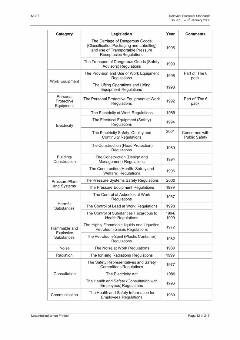
4.2.3 UK Health and Safety Legislation
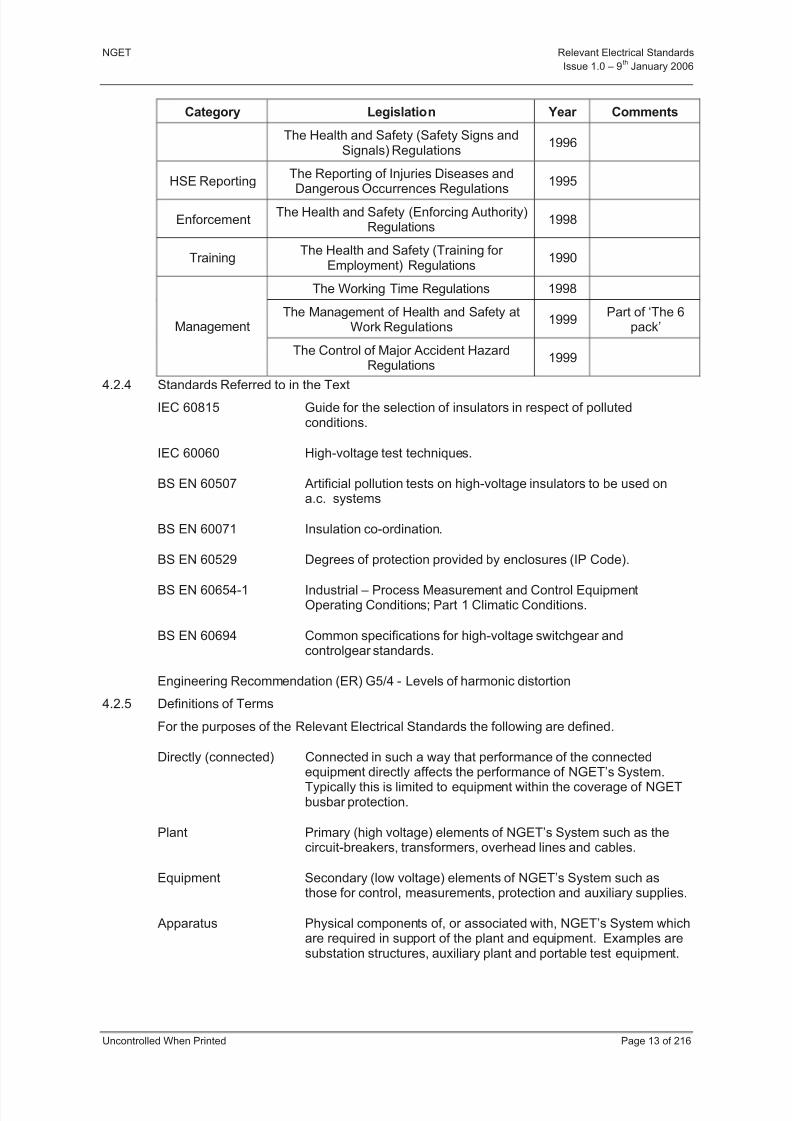
Category Legislation Year Comments
Health and Safety at Work etc Act 1974 Umbrella Act
Offices, Shops and Railway Premises Act 1963Some remaining
obligations.General
Factories Act 1961Some remaining
obligations.
The Health and Safety (First Aid)
Regulations
1981
The Workplace (Health, Safety andWelfare) Regulations
1992Part of ‘The 6
pack’The Workplace
The Confined Spaces Regulations 1997
Display ScreenEquipment
The Health and Safety (Display ScreenEquipment) Regulations
1992Part of ‘The 6
pack’
The Fire Precautions Act 1971
Fire The Fire Precautions (Workplace)Regulations
1997/1999
Handling and
Transportation
The Manual Handling Operations
Regulations1992
Part of ‘The 6
pack’
8/3/2019 1 Relevant Standards for Substation Plants
http://slidepdf.com/reader/full/1-relevant-standards-for-substation-plants 19/223
NGET Relevant Electrical Standards
Issue 1.0 – 9th
January 2006
Uncontrolled When Printed Page 12 of 216
Category Legislation Year Comments
The Carriage of Dangerous Goods(Classification Packaging and Labelling)
and use of Transportable PressureReceptacles Regulations
1996
The Transport of Dangerous Goods (SafetyAdvisors) Regulations
1999
The Provision and Use of Work EquipmentRegulations
1998Part of ‘The 6
pack’Work Equipment
The Lifting Operations and LiftingEquipment Regulations
1998
PersonalProtectiveEquipment
The Personal Protective Equipment at WorkRegulations
1992Part of ‘The 6
pack’
The Electricity at Work Regulations 1989
The Electrical Equipment (Safety)Regulations
1994Electricity
The Electricity Safety, Quality andContinuity Regulations
2001 Concerned withPublic Safety
The Construction (Head Protection)Regulations
1989
The Construction (Design andManagement) Regulations
1994Building/
Construction
The Construction (Health, Safety andWelfare) Regulations
1996
The Pressure Systems Safety Regulations 2000Pressure Plantand Systems The Pressure Equipment Regulations 1999
The Control of Asbestos at WorkRegulations
1987
The Control of Lead at Work Regulations 1998Harmful
Substances
The Control of Substances Hazardous toHealth Regulations
1994/1999
The Highly Flammable liquids and LiquefiedPetroleum Gases Regulations
1972Flammable and
ExplosiveSubstances The Petroleum-Spirit (Plastic Container)Regulations
1982
Noise The Noise at Work Regulations 1989
Radiation The Ionising Radiations Regulations 1999
The Safety Representatives and SafetyCommittees Regulations
1977
The Electricity Act 1989Consultation
The Health and Safety (Consultation withEmployees) Regulations
1996
Communication The Health and Safety Information for Employees Regulations
1989
8/3/2019 1 Relevant Standards for Substation Plants
http://slidepdf.com/reader/full/1-relevant-standards-for-substation-plants 20/223
NGET Relevant Electrical Standards
Issue 1.0 – 9th
January 2006
Uncontrolled When Printed Page 13 of 216
Category Legislation Year Comments
The Health and Safety (Safety Signs andSignals) Regulations
1996
HSE ReportingThe Reporting of Injuries Diseases and
Dangerous Occurrences Regulations
1995
EnforcementThe Health and Safety (Enforcing Authority)
Regulations1998
TrainingThe Health and Safety (Training for
Employment) Regulations1990
The Working Time Regulations 1998
The Management of Health and Safety atWork Regulations
1999Part of ‘The 6
pack’Management
The Control of Major Accident HazardRegulations
1999
4.2.4 Standards Referred to in the Text
IEC 60815 Guide for the selection of insulators in respect of pollutedconditions.
IEC 60060 High-voltage test techniques.
BS EN 60507 Artificial pollution tests on high-voltage insulators to be used ona.c. systems
BS EN 60071 Insulation co-ordination.
BS EN 60529 Degrees of protection provided by enclosures (IP Code).
BS EN 60654-1 Industrial – Process Measurement and Control EquipmentOperating Conditions; Part 1 Climatic Conditions.
BS EN 60694 Common specifications for high-voltage switchgear andcontrolgear standards.
Engineering Recommendation (ER) G5/4 - Levels of harmonic distortion
4.2.5 Definitions of Terms
For the purposes of the Relevant Electrical Standards the following are defined.
Directly (connected) Connected in such a way that performance of the connected
equipment directly affects the performance of NGET’s System.Typically this is limited to equipment within the coverage of NGETbusbar protection.
Plant Primary (high voltage) elements of NGET’s System such as thecircuit-breakers, transformers, overhead lines and cables.
Equipment Secondary (low voltage) elements of NGET’s System such asthose for control, measurements, protection and auxiliary supplies.
Apparatus Physical components of, or associated with, NGET’s System whichare required in support of the plant and equipment. Examples aresubstation structures, auxiliary plant and portable test equipment.
8/3/2019 1 Relevant Standards for Substation Plants
http://slidepdf.com/reader/full/1-relevant-standards-for-substation-plants 21/223
NGET Relevant Electrical Standards
Issue 1.0 – 9th
January 2006
Uncontrolled When Printed Page 14 of 216
Contract Enquiry Doc The commercial requirement document of NGET for a specificapplication.
4.3 SERVICE (ENVIRONMENTAL) CONDITIONS
4.3.1 General
Plant, equipment and apparatus shall be suitable for operation under the following normaland special service conditions.
4.3.2 Normal Service Conditions
Normal service conditions, as defined in BS EN 60694, are applicable. The following sub-clauses define NGET requirements where a choice of severity is required or where therequirements of BS EN 60694 are inappropriate.
a) Indoor
(i) Temperature class minus 5 indoor.
b) Outdoor
(i) Temperature class minus 25 outdoor.
(ii) Ice coating class 10 mm.
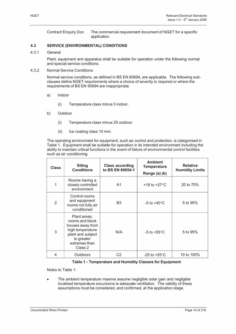
The operating environment for equipment, such as control and protection, is categorised inTable 1. Equipment shall be suitable for operation in its intended environment including theability to maintain critical functions in the event of failure of environmental control facilitiessuch as air conditioning.
ClassSiting
ConditionsClass accordingto BS EN 60654-1
AmbientTemperature
Range (a) (b)
RelativeHumidity Limits
1Rooms having aclosely controlled
environmentA1 +18 to +27C 20 to 75%
2
Control roomsand equipment
rooms not fully air conditioned
B3 -5 to +40C 5 to 95%
3
Plant areas,rooms and block
houses away from
high temperatureplant and subject
to greater extremes than
Class 2
N/A -5 to +55C 5 to 95%
4 Outdoors C2 -25 to +55C 10 to 100%
Table 1 - Temperature and Humidity Classes for Equipment
Notes to Table 1:
The ambient temperature maxima assume negligible solar gain and negligiblelocalised temperature excursions ie adequate ventilation. The validity of these
assumptions must be considered, and confirmed, at the application stage.

8/3/2019 1 Relevant Standards for Substation Plants
http://slidepdf.com/reader/full/1-relevant-standards-for-substation-plants 22/223
NGET Relevant Electrical Standards
Issue 1.0 – 9th
January 2006
Uncontrolled When Printed Page 15 of 216
For ventilated equipment the ambient temperature is defined as being the free air temperature existing at a point level with the top of the equipment.
4.3.3 Special Service Conditions
Plant & equipment shall be suitable for operation in a pollution environment as defined inTable 2.
External insulation shall be in accordance with the relevant requirements andrecommendations of IEC 60815.
For ceramic insulation, test conditions to prove this performance level shall be as defined inTables 2 & 3. Service experience offered in lieu of artificial pollution testing shall identical tothat detailed for composite insulation detailed in this clause.
Insulation, including composite insulation, shall have a minimum specific creepage of 25mm/kV for Class III pollution environments and 31mm/kV for Class IV pollutionenvironments. Account shall be taken of the factor kD.
Ceramic insulation for vertical application meeting the following criteria is deemed to meetthe requirements of Tables 2 & 3 without further testing.
Alternate Long Short (ALS) profile.
(p1 – p2) 15 mm
s 70mm
InsulationIEC 60815 Pollution
Class
IEC 507 Salt FogWithstand TestSpecification
kg/m3
NGET Heavy WettingTest Specification
kg/m3
Indoor INo test withstand
requiredNo test withstand
required
Outdoor III 80 80
Outdoor (special)
IV >160 > 160
Outdoor Horizontal
III & IV 80 80
Table 2 - Pollution, Salt Fog and Heavy Wetting Test Requirements
Informative: Pollution Class IV may be specified in the contract enquiry document for siteswhich are judged to be subject to severe coastal or industrial pollution.
Informative: Details of the heavy wetting specification can be found in 5.8.
8/3/2019 1 Relevant Standards for Substation Plants
http://slidepdf.com/reader/full/1-relevant-standards-for-substation-plants 23/223
NGET Relevant Electrical Standards
Issue 1.0 – 9th
January 2006
Uncontrolled When Printed Page 16 of 216
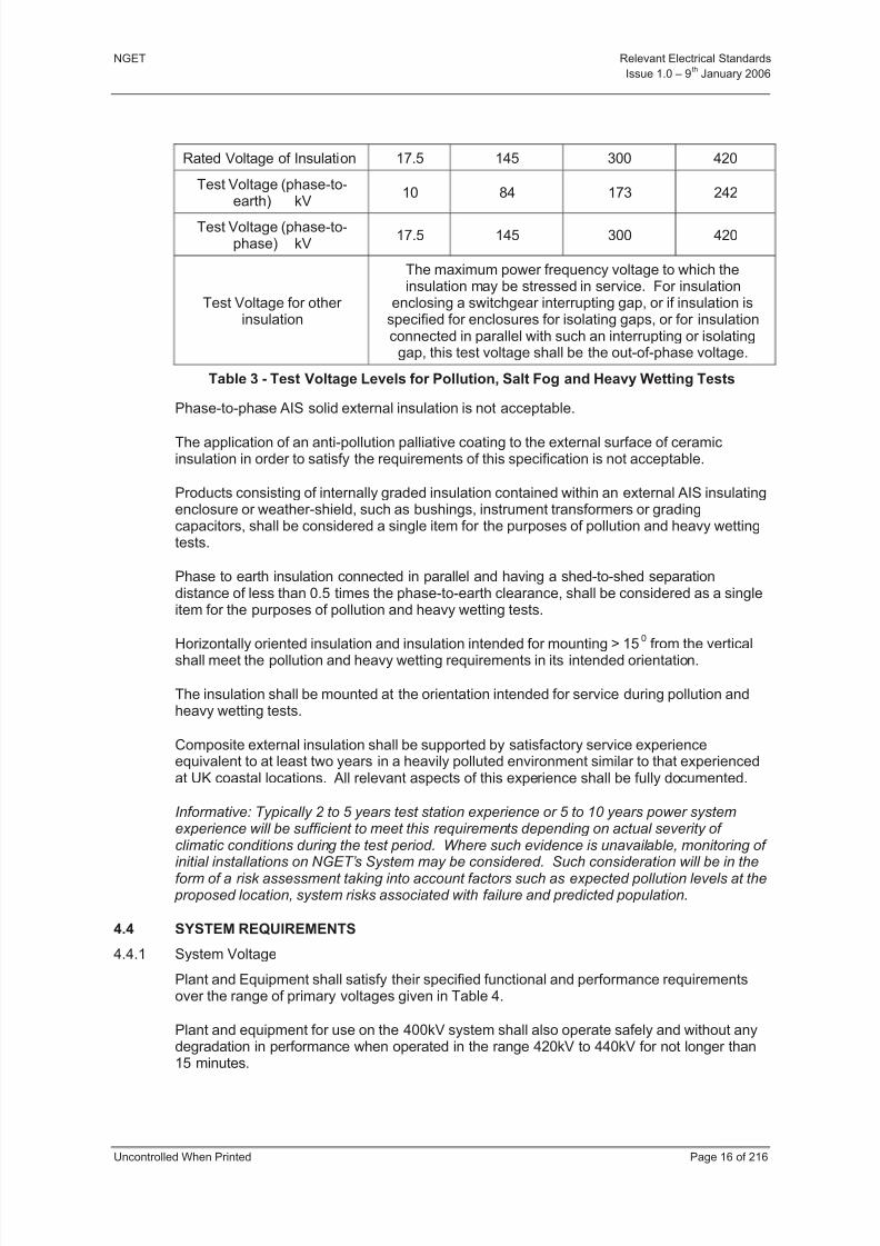
Rated Voltage of Insulation 17.5 145 300 420
Test Voltage (phase-to-earth) kV
10 84 173 242
Test Voltage (phase-to-phase) kV
17.5 145 300 420
Test Voltage for other insulation
The maximum power frequency voltage to which theinsulation may be stressed in service. For insulation
enclosing a switchgear interrupting gap, or if insulation isspecified for enclosures for isolating gaps, or for insulationconnected in parallel with such an interrupting or isolating
gap, this test voltage shall be the out-of-phase voltage.
Table 3 - Test Voltage Levels for Pollution, Salt Fog and Heavy Wetting Tests
Phase-to-phase AIS solid external insulation is not acceptable.
The application of an anti-pollution palliative coating to the external surface of ceramicinsulation in order to satisfy the requirements of this specification is not acceptable.
Products consisting of internally graded insulation contained within an external AIS insulatingenclosure or weather-shield, such as bushings, instrument transformers or gradingcapacitors, shall be considered a single item for the purposes of pollution and heavy wettingtests.
Phase to earth insulation connected in parallel and having a shed-to-shed separationdistance of less than 0.5 times the phase-to-earth clearance, shall be considered as a singleitem for the purposes of pollution and heavy wetting tests.
Horizontally oriented insulation and insulation intended for mounting > 150
from the verticalshall meet the pollution and heavy wetting requirements in its intended orientation.
The insulation shall be mounted at the orientation intended for service during pollution andheavy wetting tests.
Composite external insulation shall be supported by satisfactory service experienceequivalent to at least two years in a heavily polluted environment similar to that experiencedat UK coastal locations. All relevant aspects of this experience shall be fully documented.
Informative: Typically 2 to 5 years test station experience or 5 to 10 years power systemexperience will be sufficient to meet this requirements depending on actual severity of climatic conditions during the test period. Where such evidence is unavailable, monitoring of
initial installations on NGET’s System may be considered. Such consideration will be in theform of a risk assessment taking into account factors such as expected pollution levels at the proposed location, system risks associated with failure and predicted population.
4.4 SYSTEM REQUIREMENTS
4.4.1 System Voltage
Plant and Equipment shall satisfy their specified functional and performance requirementsover the range of primary voltages given in Table 4.
Plant and equipment for use on the 400kV system shall also operate safely and without anydegradation in performance when operated in the range 420kV to 440kV for not longer than15 minutes.

8/3/2019 1 Relevant Standards for Substation Plants
http://slidepdf.com/reader/full/1-relevant-standards-for-substation-plants 24/223
NGET Relevant Electrical Standards
Issue 1.0 – 9th
January 2006
Uncontrolled When Printed Page 17 of 216
Plant and equipment shall satisfy their specified functional and performance requirementswith phase voltage unbalance up to a maximum of 1%.
Informative: Phase voltage unbalance up to 2%, on an infrequent, short duration basis, may be specified at some sites.
Plant and equipment shall satisfy their specified functional and performance requirementswhen exposed to harmonic distortion levels in the voltage waveform up to the compatibilitylevels specified in Appendix A of ER G5/4.
Nominal System voltage(phase to phase)
400 kV 275 kV 132 kV 13 kV tertiary
Maximum continuousSystem voltage
420 kV 303 kV 145 kV 16.9 kV
Minimum continuousSystem voltage
360 kV 247 kV 119 kV 10.4 kV
Rated voltage of plant 420 kV 300 kV 145 kV 17.5 kV
Table 4 - System Voltage
4.4.2 System Frequency
Plant and Equipment shall satisfy their specified functional and performance requirementsover the range of frequencies given in Table 5.
Plant and equipment shall also operate safely and without any degradation in performancewithin the following frequency ranges:
a) 47Hz to 47.5Hz for at least 20 seconds
b) 50.5Hz to 52 Hz continuous
Rated frequency 50 Hz
Maximum continuous frequency 50.5 Hz
Minimum continuous frequency 47.5 Hz
Table 5 - System Frequency
4.4.3 Earthing of System Neutral
Plant and Equipment shall satisfy their specified functional and performance requirementsunder the neutral earthing condition given in Table 6.
Nominal Voltage(kV)
Maximum Earth Fault Factor Earthing Type
400, 275, and 132 1.4 Multiple direct
13 (tertiary) Site specific Site specific
Table 6 - Earthing of System Neutral
8/3/2019 1 Relevant Standards for Substation Plants
http://slidepdf.com/reader/full/1-relevant-standards-for-substation-plants 25/223
NGET Relevant Electrical Standards
Issue 1.0 – 9th
January 2006
Uncontrolled When Printed Page 18 of 216
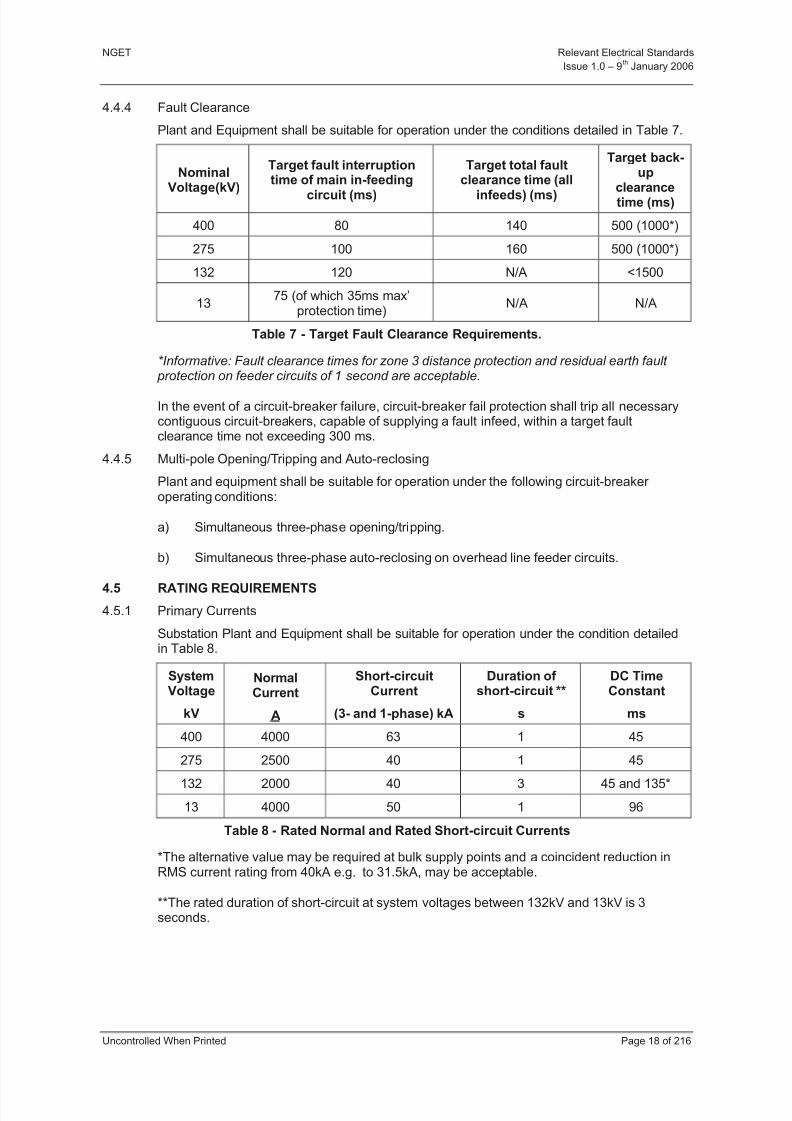
4.4.4 Fault Clearance
Plant and Equipment shall be suitable for operation under the conditions detailed in Table 7.
Nominal
Voltage(kV)
Target fault interruptiontime of main in-feeding
circuit (ms)
Target total faultclearance time (all
infeeds) (ms)
Target back-up
clearancetime (ms)
400 80 140 500 (1000*)
275 100 160 500 (1000*)
132 120 N/A <1500
1375 (of which 35ms max’
protection time)N/A N/A
Table 7 - Target Fault Clearance Requirements.
*Informative: Fault clearance times for zone 3 distance protection and residual earth fault protection on feeder circuits of 1 second are acceptable.
In the event of a circuit-breaker failure, circuit-breaker fail protection shall trip all necessarycontiguous circuit-breakers, capable of supplying a fault infeed, within a target faultclearance time not exceeding 300 ms.
4.4.5 Multi-pole Opening/Tripping and Auto-reclosing
Plant and equipment shall be suitable for operation under the following circuit-breaker operating conditions:
a) Simultaneous three-phase opening/tripping.
b) Simultaneous three-phase auto-reclosing on overhead line feeder circuits.
4.5 RATING REQUIREMENTS
4.5.1 Primary Currents
Substation Plant and Equipment shall be suitable for operation under the condition detailedin Table 8.
SystemVoltage
kV
NormalCurrent
A
Short-circuitCurrent
(3- and 1-phase) kA
Duration of short-circuit **
s
DC TimeConstant
ms
400 4000 63 1 45
275 2500 40 1 45
132 2000 40 3 45 and 135*
13 4000 50 1 96
Table 8 - Rated Normal and Rated Short-circuit Currents
*The alternative value may be required at bulk supply points and a coincident reduction inRMS current rating from 40kA e.g. to 31.5kA, may be acceptable.
**The rated duration of short-circuit at system voltages between 132kV and 13kV is 3seconds.
8/3/2019 1 Relevant Standards for Substation Plants
http://slidepdf.com/reader/full/1-relevant-standards-for-substation-plants 26/223
NGET Relevant Electrical Standards
Issue 1.0 – 9th
January 2006
Uncontrolled When Printed Page 19 of 216
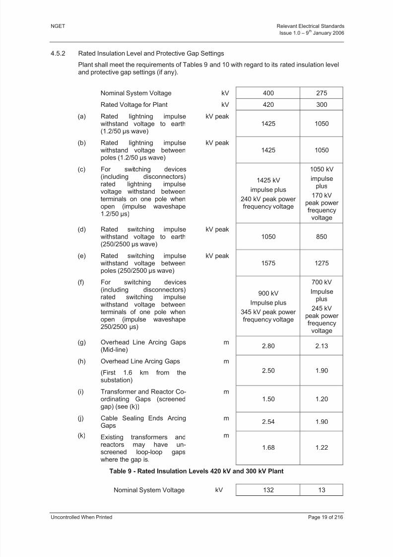
4.5.2 Rated Insulation Level and Protective Gap Settings
Plant shall meet the requirements of Tables 9 and 10 with regard to its rated insulation leveland protective gap settings (if any).
Nominal System Voltage kV 400 275Rated Voltage for Plant kV 420 300
(a) Rated lightning impulsewithstand voltage to earth(1.2/50 µs wave)
kV peak1425 1050
(b) Rated lightning impulsewithstand voltage betweenpoles (1.2/50 µs wave)
kV peak1425 1050
(c) For switching devices(including disconnectors)rated lightning impulse
voltage withstand betweenterminals on one pole whenopen (impulse waveshape1.2/50 µs)
1425 kV
impulse plus240 kV peak power frequency voltage
1050 kV
impulseplus
170 kVpeak power frequency
voltage
(d) Rated switching impulsewithstand voltage to earth(250/2500 µs wave)
kV peak1050 850
(e) Rated switching impulsewithstand voltage betweenpoles (250/2500 µs wave)
kV peak1575 1275
(f) For switching devices
(including disconnectors)rated switching impulsewithstand voltage betweenterminals of one pole whenopen (impulse waveshape250/2500 µs)
900 kV
Impulse plus
345 kV peak power frequency voltage
700 kV
Impulseplus
245 kVpeak power frequency
voltage
(g) Overhead Line Arcing Gaps(Mid-line)
m2.80 2.13
(h) Overhead Line Arcing Gaps
(First 1.6 km from the
substation)
m
2.50 1.90
(i) Transformer and Reactor Co-ordinating Gaps (screenedgap) (see (k))
m1.50 1.20
(j) Cable Sealing Ends ArcingGaps
m2.54 1.90
(k) Existing transformers andreactors may have un-screened loop-loop gapswhere the gap is.
m
1.68 1.22
Table 9 - Rated Insulation Levels 420 kV and 300 kV Plant
Nominal System Voltage kV 132 13

8/3/2019 1 Relevant Standards for Substation Plants
http://slidepdf.com/reader/full/1-relevant-standards-for-substation-plants 27/223
NGET Relevant Electrical Standards
Issue 1.0 – 9th
January 2006
Uncontrolled When Printed Page 20 of 216
Rated Voltage for Plant kV 145 17.5
(a)Rated lightning impulse withstandvoltage to earth (1.2/50 µs wave)
kV peak 650 95
(b)
Rated lightning impulse withstand
voltage between poles (1.2/50 µswave) kV peak 650 95
(c)
For switching devices other thandisconnectors and switch-
disconnectors rated lightningimpulse withstand voltage
between terminals on one polewhen open (1.2/50 µs wave)
kV peak 650 95
(d)
For disconnectors and switch-disconnectors rated lightning
impulse withstand voltagebetween terminals on one pole
when open(1.2/50 µs wave)
kV peak 750 110
(e)Rated power frequency drywithstand voltage (1 minute)
kV 275 38
(f)
For open type equipment ratedpower frequency wet withstand
voltage (1 minute) (preferred method is BS923)
kV 275 38
(g)
Across the isolating distance of disconnectors rated power frequency dry, and where
applicable wet, withstand voltage
(1 minute)
kV 315 45
(h)Overhead Line Arcing Gaps (Mid-
line)m 1.10 N/A
(i)Overhead Line Arcing Gaps (first
1.6 km from the substation)m 1.00 N/A
(j)Transformers and Reactor Co-
ordinating Gaps (see (l))m
0.66screened gap
0.10arcing gap
(k) Cable Sealing Ends Arcing Gap m 1.00 0.10
(l)Existing 132 kV transformers andreactors may have un-screened
loop-loop gaps
m 0.66 –
Table 10 - Rated Insulation Levels for 145 kV Plant & for 13 kV Tertiary ConnectedPlant
4.6 GENERAL REQUIREMENTS
4.6.1 Equipment orientation
Plant shall be type tested in the orientation in which it is intended to be applied. Applicationsin orientations other than that which was tested are unacceptable.
8/3/2019 1 Relevant Standards for Substation Plants
http://slidepdf.com/reader/full/1-relevant-standards-for-substation-plants 28/223
NGET Relevant Electrical Standards
Issue 1.0 – 9th
January 2006
Uncontrolled When Printed Page 21 of 216
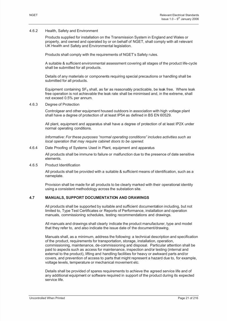
4.6.2 Health, Safety and Environment
Products supplied for installation on the Transmission System in England and Wales or property, and owned and operated by or on behalf of NGET, shall comply with all relevantUK Health and Safety and Environmental legislation.
Products shall comply with the requirements of NGET’s Safety rules.
A suitable & sufficient environmental assessment covering all stages of the product life-cycleshall be submitted for all products.
Details of any materials or components requiring special precautions or handling shall besubmitted for all products.
Equipment containing SF6 shall, as far as reasonably practicable, be leak free. Where leakfree operation is not achievable the leak rate shall be minimised and, in the extreme, shallnot exceed 0.5% per annum.
4.6.3 Degree of Protection
Controlgear and other equipment housed outdoors in association with high voltage plantshall have a degree of protection of at least IP54 as defined in BS EN 60529.
All plant, equipment and apparatus shall have a degree of protection of at least IP2X under normal operating conditions.
Informative: For these purposes “normal operating conditions” includes activities such aslocal operation that may require cabinet doors to be opened.
4.6.4 Date Proofing of Systems Used in Plant, equipment and apparatus
All products shall be immune to failure or malfunction due to the presence of date sensitiveelements.
4.6.5 Product IdentificationAll products shall be provided with a suitable & sufficient means of identification, such as anameplate.
Provision shall be made for all products to be clearly marked with their operational identityusing a consistent methodology across the substation site.
4.7 MANUALS, SUPPORT DOCUMENTATION AND DRAWINGS
All products shall be supported by suitable and sufficient documentation including, but notlimited to, Type Test Certificates or Reports of Performance, installation and operationmanuals, commissioning schedules, testing recommendations and drawings.
All manuals and drawings shall clearly indicate the product manufacturer, type and modelthat they refer to, and also indicate the issue date of the document/drawing.
Manuals shall, as a minimum, address the following: a technical description and specificationof the product, requirements for transportation, storage, installation, operation,commissioning, maintenance, de-commissioning and disposal. Particular attention shall bepaid to aspects such as access for maintenance, inspection and/or testing (internal andexternal to the product), lifting and handling facilities for heavy or awkward parts and/or covers, and prevention of access to parts that might represent a hazard due to, for example,voltage levels, temperature or mechanical movement etc.
Details shall be provided of spares requirements to achieve the agreed service life and of
any additional equipment or software required in support of the product during its expectedservice life.

8/3/2019 1 Relevant Standards for Substation Plants
http://slidepdf.com/reader/full/1-relevant-standards-for-substation-plants 29/223
NGET Relevant Electrical Standards
Issue 1.0 – 9th
January 2006
Uncontrolled When Printed Page 22 of 216
Informative: It is preferable for installation manuals to be physically separate from operationand maintenance manuals.
4.8 GUIDANCE NOTES - HEAVY WETTING TEST SPECIFICATION
(This Guidance Note does not form part of the RES document)
4.8.1 General Test Requirements
The Heavy Wetting Test is used to establish the performance of a polluted insulator whenexposed to the sudden application of heavy wetting.
The general test requirements are as in BS EN 60507 Clauses 5 and 6.
4.8.2 Preconditioning Process
The insulator shall be preconditioned as required by BS EN 60507 Clause 10 beforeperforming the test.
4.8.3 Heavy Wetting Test
The intention of the test is to confirm the specified heavy wetting withstand salinity of theinsulator at the specified test voltage.
Referring to clauses in BS EN 60507 the test shall start when the test insulator and thechamber conditions fulfill the requirements of Clause 9, and after the preconditioning of theinsulator according to Clause 10.
A series of tests shall be performed on the insulator as detailed below. Each test consists of three stages.
a) Stage 1 Salt Fog
The specified test voltage, in accordance with Table 3 of this document shall be
applied to the insulator which shall be exposed to a salt fog using a salt solutionhaving the specified test salinity in accordance with Table 2 of this document.Flashovers during this stage do not constitute a failure of the heavy wetting test. After a flashover, the insulator shall immediately be re-energised at a voltage level 5%below the flashover voltage. This process may be repeated if further flashovers occur.The total period of application of salt fog shall be 15 minutes.
b) Stage 2 Drying
The insulator is allowed to dry initially at the voltage level reached at the end of Stage1. During the drying period the test voltage shall be increased if necessary to thespecified test voltage. Flashovers during this stage do not constitute a failure in thetest. After a flashover the insulator shall be immediately re-energised to continue the
drying process. The total drying period shall be 15 minutes.
c) Stage 3 Heavy Wetting
Immediately following Stage 2 and at the specified test voltage, the insulator shall besprayed with water as specified in the IEC 60060-1 Standard Wet Test Procedureexcept that the water conductivity shall be 100 µS.mm-1. The wetting shall continueuntil flashover or until the discharge activity has decreased to a stable level at whichflashover cannot occur. If this cannot be determined then the wetting shall continuefor 15 minutes.
d) Acceptance Criteria for the Heavy Wetting Test
The insulator complies with this specification if no flashover occurs during the Stage 3Heavy Wetting tests in a series of three consecutive tests. A single test consists of

8/3/2019 1 Relevant Standards for Substation Plants
http://slidepdf.com/reader/full/1-relevant-standards-for-substation-plants 30/223
NGET Relevant Electrical Standards
Issue 1.0 – 9th
January 2006
Uncontrolled When Printed Page 23 of 216
the complete sequence of all 3 stages in accordance with the above procedure. If only one flashover occurs, a fourth test shall be performed and the insulator thenpasses the test if no flashover occurs in this final test.
8/3/2019 1 Relevant Standards for Substation Plants
http://slidepdf.com/reader/full/1-relevant-standards-for-substation-plants 31/223
NGET Relevant Electrical Standards
Issue 1.0 – 9th
January 2006
Uncontrolled When Printed Page 24 of 216
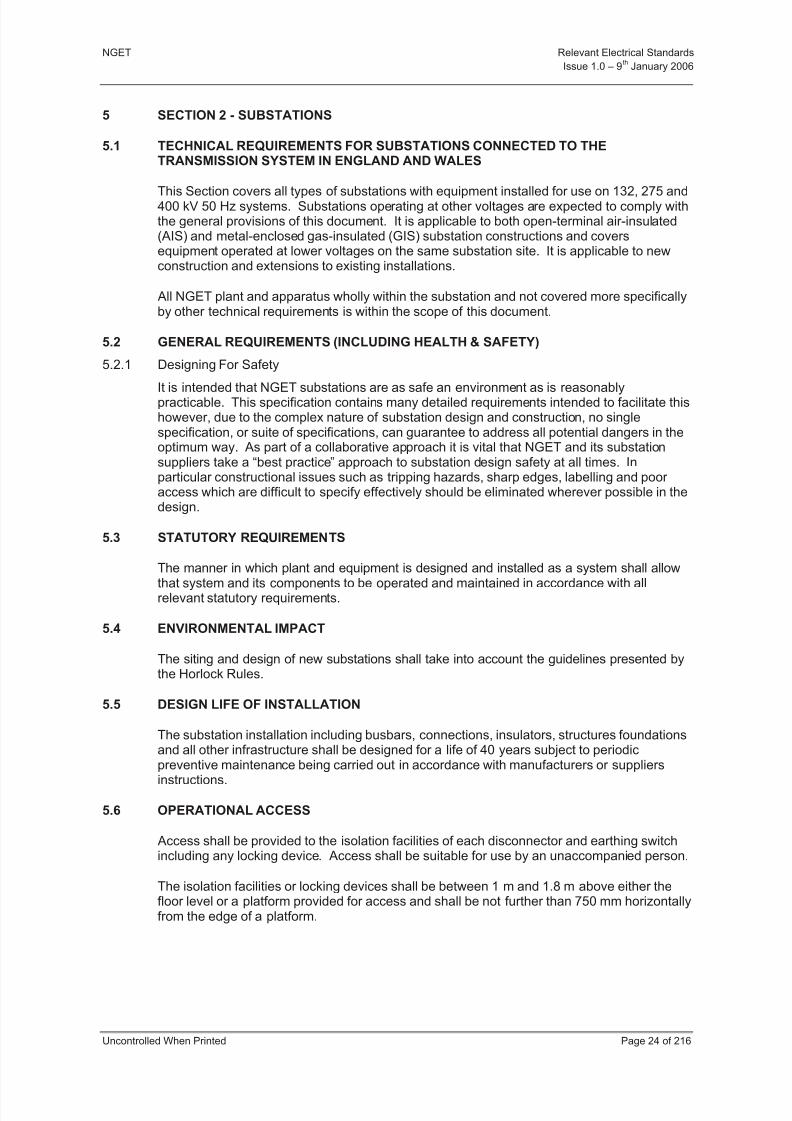
5 SECTION 2 - SUBSTATIONS
5.1 TECHNICAL REQUIREMENTS FOR SUBSTATIONS CONNECTED TO THETRANSMISSION SYSTEM IN ENGLAND AND WALES
This Section covers all types of substations with equipment installed for use on 132, 275 and400 kV 50 Hz systems. Substations operating at other voltages are expected to comply withthe general provisions of this document. It is applicable to both open-terminal air-insulated(AIS) and metal-enclosed gas-insulated (GIS) substation constructions and coversequipment operated at lower voltages on the same substation site. It is applicable to newconstruction and extensions to existing installations.
All NGET plant and apparatus wholly within the substation and not covered more specificallyby other technical requirements is within the scope of this document.
5.2 GENERAL REQUIREMENTS (INCLUDING HEALTH & SAFETY)
5.2.1 Designing For Safety
It is intended that NGET substations are as safe an environment as is reasonablypracticable. This specification contains many detailed requirements intended to facilitate thishowever, due to the complex nature of substation design and construction, no singlespecification, or suite of specifications, can guarantee to address all potential dangers in theoptimum way. As part of a collaborative approach it is vital that NGET and its substationsuppliers take a “best practice” approach to substation design safety at all times. Inparticular constructional issues such as tripping hazards, sharp edges, labelling and poor access which are difficult to specify effectively should be eliminated wherever possible in thedesign.
5.3 STATUTORY REQUIREMENTS
The manner in which plant and equipment is designed and installed as a system shall allow
that system and its components to be operated and maintained in accordance with allrelevant statutory requirements.
5.4 ENVIRONMENTAL IMPACT
The siting and design of new substations shall take into account the guidelines presented bythe Horlock Rules.
5.5 DESIGN LIFE OF INSTALLATION
The substation installation including busbars, connections, insulators, structures foundationsand all other infrastructure shall be designed for a life of 40 years subject to periodic
preventive maintenance being carried out in accordance with manufacturers or suppliersinstructions.
5.6 OPERATIONAL ACCESS
Access shall be provided to the isolation facilities of each disconnector and earthing switchincluding any locking device. Access shall be suitable for use by an unaccompanied person.
The isolation facilities or locking devices shall be between 1 m and 1.8 m above either thefloor level or a platform provided for access and shall be not further than 750 mm horizontallyfrom the edge of a platform.
8/3/2019 1 Relevant Standards for Substation Plants
http://slidepdf.com/reader/full/1-relevant-standards-for-substation-plants 32/223
NGET Relevant Electrical Standards
Issue 1.0 – 9th
January 2006
Uncontrolled When Printed Page 25 of 216
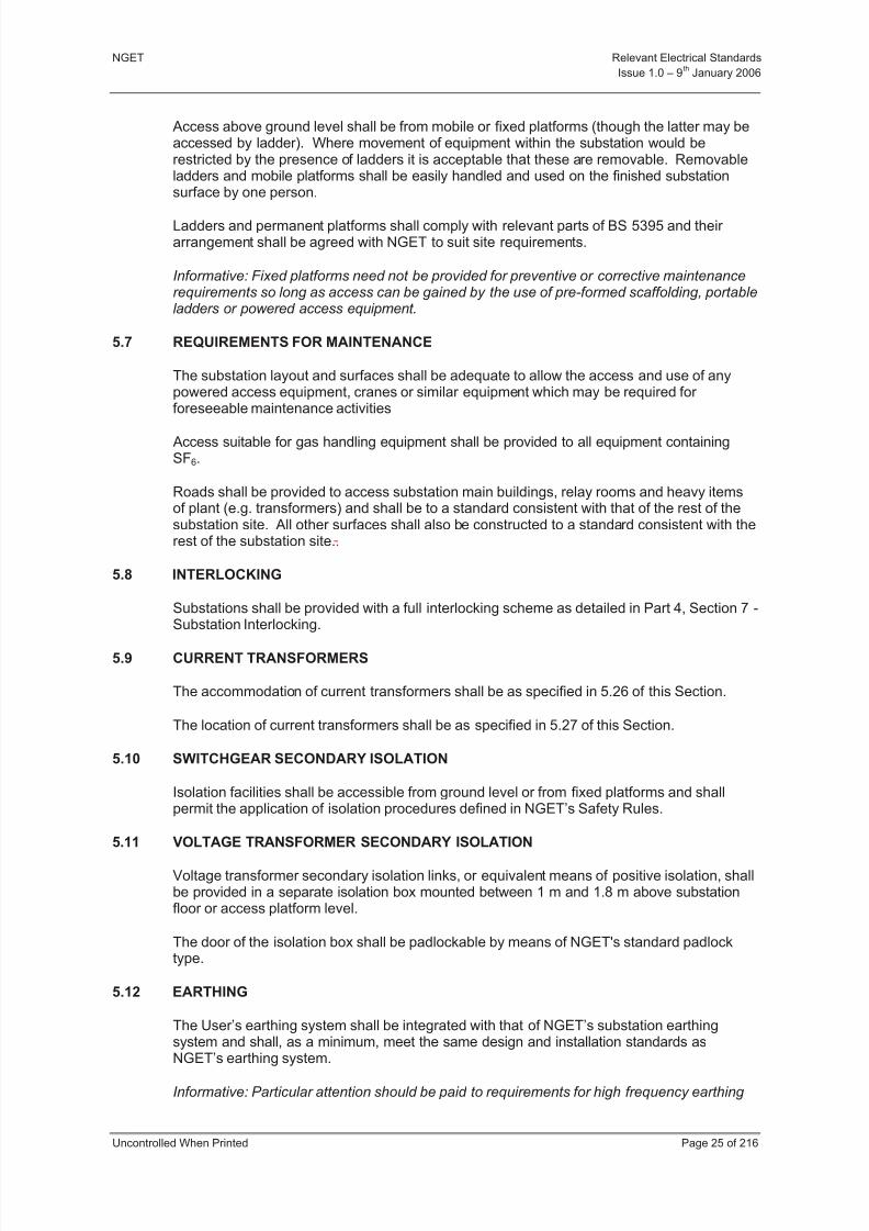
Access above ground level shall be from mobile or fixed platforms (though the latter may beaccessed by ladder). Where movement of equipment within the substation would berestricted by the presence of ladders it is acceptable that these are removable. Removableladders and mobile platforms shall be easily handled and used on the finished substationsurface by one person.
Ladders and permanent platforms shall comply with relevant parts of BS 5395 and their arrangement shall be agreed with NGET to suit site requirements.
Informative: Fixed platforms need not be provided for preventive or corrective maintenancerequirements so long as access can be gained by the use of pre-formed scaffolding, portableladders or powered access equipment.
5.7 REQUIREMENTS FOR MAINTENANCE
The substation layout and surfaces shall be adequate to allow the access and use of anypowered access equipment, cranes or similar equipment which may be required for foreseeable maintenance activities
Access suitable for gas handling equipment shall be provided to all equipment containingSF6.
Roads shall be provided to access substation main buildings, relay rooms and heavy itemsof plant (e.g. transformers) and shall be to a standard consistent with that of the rest of thesubstation site. All other surfaces shall also be constructed to a standard consistent with therest of the substation site..
5.8 INTERLOCKING
Substations shall be provided with a full interlocking scheme as detailed in Part 4, Section 7 -Substation Interlocking.
5.9 CURRENT TRANSFORMERS
The accommodation of current transformers shall be as specified in 5.26 of this Section.
The location of current transformers shall be as specified in 5.27 of this Section.
5.10 SWITCHGEAR SECONDARY ISOLATION
Isolation facilities shall be accessible from ground level or from fixed platforms and shallpermit the application of isolation procedures defined in NGET’s Safety Rules.
5.11 VOLTAGE TRANSFORMER SECONDARY ISOLATION
Voltage transformer secondary isolation links, or equivalent means of positive isolation, shallbe provided in a separate isolation box mounted between 1 m and 1.8 m above substationfloor or access platform level.
The door of the isolation box shall be padlockable by means of NGET's standard padlocktype.
5.12 EARTHING
The User’s earthing system shall be integrated with that of NGET’s substation earthingsystem and shall, as a minimum, meet the same design and installation standards as
NGET’s earthing system.
Informative: Particular attention should be paid to requirements for high frequency earthing
8/3/2019 1 Relevant Standards for Substation Plants
http://slidepdf.com/reader/full/1-relevant-standards-for-substation-plants 33/223
NGET Relevant Electrical Standards
Issue 1.0 – 9th
January 2006
Uncontrolled When Printed Page 26 of 216
5.13 PLANT AND EQUIPMENT IDENTIFICATION
Labels shall be provided to allow unambiguous identification of all plant and equipment andof associated operating facilities and points of isolation. The following are required:
a) Each circuit-breaker, disconnector and earthing switch mechanism box shall carry alabel giving the operational reference of the device.
b) Each pressure gauge or pressure readout device shall carry a label identifying theparameter it is monitoring.
c) Each valve (including self-sealing gas filling valves) shall carry a label identifying itsfunction.
d) Each SF6 filling valve shall be provided with a label identifying the mass of gascontained within the gas compartment to which it is fitted (at normal filling density).The volume of the compartment and normal filling density shall also be marked.
e) Each control handle or switch for plant operation shall carry a label identifying itsfunction.
f) Each point of LV isolation associated with plant shall carry a label identifying itsfunction.
g) Each cabinet, cubicle or kiosk shall carry a label identifying all of the equipmentcontained within it.
Labels shall be sufficiently durable for the application and the environment in which they areto be used taking account of the expected operational lifetime of the equipment. They shallremain in place and legible for the design lifetime of the equipment.
Informative: Experience indicates that this requirement can be met by the use of UV resistant engraved labels with mechanical fixings. NGET will require demonstration that alternativelabelling systems are adequate
The fixing of labels shall not compromise the degree of protection (IP rating) of theequipment.
All pipework shall be identified in accordance with BS 1710.
5.14 LIGHT CURRENT EQUIPMENT
Electronic equipment shall be located in accommodation commensurate with itsenvironmental performance, which is classified in Part 4 -Section 16.
Light current accommodation shall meet the requirements of Part 4 - Section 16, Class 3under all ambient conditions.
Fixed heating shall be thermostatically controlled.
Where no fixed heating is provided, provision shall be made for raising the air temperature in
the vicinity of all equipment associated with any one circuit to 16C without causingcondensation on the equipment.
All panels housing secondary equipment which are sited in equipment rooms or accommodation shared with equipment owned by other users shall be padlockable.
8/3/2019 1 Relevant Standards for Substation Plants
http://slidepdf.com/reader/full/1-relevant-standards-for-substation-plants 34/223
NGET Relevant Electrical Standards
Issue 1.0 – 9th
January 2006
Uncontrolled When Printed Page 27 of 216
5.15 SUBSTATION AUXILIARY CABLING
All substation auxiliary cabling between substation buildings, relay rooms, commonmarshalling points and substation primary equipment shall, as far as reasonably practicable,be installed in buried cable ducts. Where cable trays (or similar) are used these shall not
present a risk of injury and shall be suitably finished to prevent degradation due toenvironmental conditions. Auxiliary cables shall be installed such that they do not present atripping hazard.
Informative: The installation of substation auxiliary cabling should minimise hazards such astripping and sharp edges (cable trays). Cables between dispersed relay rooms or circuit marshalling points and local plant may be buried direct where armoured cables are used. Inall other circumstances cable ducts may be used.
The location of all buried cables and ducts shall be clearly recorded on site.
All metallic cables shall be of low smoke, low fume, zero Halogen, armoured design.Installation shall be in accordance with BS 7671.
Substation auxiliary supplies shall be designed and installed in accordance with Part 4,Section 5.
5.16 SEGREGATION OF EQUIPMENT OWNED BY NGET & OTHER USERS
Protection relays and circuits associated with equipment owned by Users (e.g. generatingcompanies, distribution companies or directly connected entities as defined in Part 4, Section1) shall be accommodated in separate panels from those associated with equipment ownedby NGET. This requirement shall also apply to multicore cable terminations, marshallingfacilities and jumper fields.
Informative: Ideally all NGET owned equipment should be physically segregated from that owned by Users however it is accepted that this is not always possible/practical in whichcase the following clauses are applicable.
Where switchgear local controls are grouped on a bay control panel (or similar) then controlof NGET owned plant shall be segregated from that of User owned plant. Separateindividually lockable local/remote control selector switches shall be provided for NGET andUser equipment such that staff with authority to operate only User equipment are unable toaccess control of NGET owned equipment.
Facilities provided for substation level control of Users equipment shall have no facilities tooperate NGET owned equipment.
Any electrical/mechanical supplies which are provided by NGET to Users equipment shall beequipped with segregated, clearly labelled isolation facilities.
48V dc, 110V dc and 400/220V ac auxiliary supply isolation facilities shall be located in theequipment local control cubicle (LCC) or, where installed in a common panel, shall be clearlysegregated from isolation facilities for NGET owned equipment. LCC’s and common panelsshould be sited in areas to which access will be permitted to non-NGET staff.
400V ac supplies to significant User loads, such as transformer coolers, shall be suppliedfrom separate circuits on the substation LVAC supplies board and provision shall be madefor the installation of metering. Isolation facilities shall be provided at the load end of thecircuit such that isolation at the LVAC board is not normally required during maintenance.
Common compressed air, hydraulic or other motive power systems supplying both NGETand Users equipment are unacceptable.
8/3/2019 1 Relevant Standards for Substation Plants
http://slidepdf.com/reader/full/1-relevant-standards-for-substation-plants 35/223
NGET Relevant Electrical Standards
Issue 1.0 – 9th
January 2006
Uncontrolled When Printed Page 28 of 216
The ownership of equipment shall be clearly labelled particularly where NGET and Usersequipment or isolation facilities are located in close proximity.
5.17 CRANES & LIFTING EQUIPMENT
Lifting beams or fixed overhead travelling cranes of adequate capacity shall be providedwhere their use is required to assist with maintenance, repair or dismantling of switchgear.Fixed cranes shall not be provided in outdoor substations or indoor AIS substations exceptwhere specifically required for maintenance or repair purposes.
Provision shall be made to inspect beams or cranes for insurance purposes and to fit liftingtackle.
5.18 FACILITIES
As a minimum the following facilities shall be provided at all new 400 kV, 275 kV and NGETowned 132kV substations.
Informative: The extent to which this Clause shall apply to extensions to existing installationsshall be specified by NGET in the Contract Enquiry.
a) Adequate toilet and washing facilities for operation and maintenance staff taking intoaccount NGET’s equal opportunities policies.
b) Adequate lighting in accordance with HS(G)38.
c) Standby control room(s) with provision to be equipped as a permit office and to beused for on-site drawing/record storage.
Informative: At indoor GIS substations access to the control room shall not be throughthe switchgear hall and the room shall prevent ingress of SF6 decomposition products
in the event of a switchgear fault.
d) At sites where SF6 gas-filled equipment is installed a standing area and suitable water and drainage connections for a mobile changing/shower facility. Where large volumesof SF6 are installed e.g. GIS substations, a fixed installation is required.
Informative: These facilities are required to comply with NGET safety codes of practicefor work on SF6 filled equipment that has been exposed to power arcing (NS-C2).
e) A small mess room with sink, worktop, electrical outlets and facilities for the supply of drinking quality water.
f) An equipment store (including earth storage facilities) / small workshop.
g) Vehicle parking.
5.19 SITE SECURITY
No equipment within the substation shall be installed within 2 m of the security fence.
5.20 FIRE PROTECTION
Fire protection shall be installed on the User bay(s) to a standard consistent with that of NGET’s substation site.

8/3/2019 1 Relevant Standards for Substation Plants
http://slidepdf.com/reader/full/1-relevant-standards-for-substation-plants 36/223
NGET Relevant Electrical Standards
Issue 1.0 – 9th
January 2006
Uncontrolled When Printed Page 29 of 216
5.21 GENERAL REQUIREMENTS SPECIFIC TO AIS SUBSTATIONS
5.21.1 Electrical Clearances
The layout of AIS equipment shall ensure the integrity of the air space between live partsand other conductors (whether earthed or at different potential) for the rated voltage
conditions for which the substation is designed.
Where equipment configurations have not been dielectrically tested in accordance with BSEN 60694 then minimum operational electrical clearances in accordance with Table 11 shallbe applied.
Nominal SystemVoltage
BIL/SILPhase-to-Earth
ClearancePhase-to-Phase
Clearance
kV (rms) kV (p)m
(Notes 1,2)M
33 170 0.5 0.43
66 325 0.7 0.78
132 650 1.1 1.4
275 1050/850 2.1 2.4
400 1425/1050 2.8 3.6
Table 11 - Substation Electrical Clearances
Informative: [Note 1] Minimum clearance of 500 mm specified to cover vermin and bird interference.
Informative: [Note 2] Under some circumstances temporary infringement of phase to earthclearances during earthing switch operation may be permitted. Such circumstances must be
agreed with NGET during the design phase.
Informative: It should be noted that Table 11 lists MINIMUM clearances and an appropriateadditional allowance should be made for constructional tolerances, effects of short-circuit,wind effects etc.
5.21.2 Safety Clearances/Distances
Safety to persons shall normally be achieved by the provision of adequate safety clearanceto live parts taking into account the need for maintenance, vehicular and pedestrian access.
Where adequate safety clearances to live parts cannot be maintained without limitingaccess, barriers or fences shall be provided.
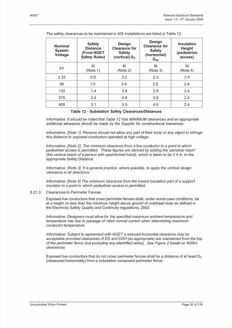
8/3/2019 1 Relevant Standards for Substation Plants
http://slidepdf.com/reader/full/1-relevant-standards-for-substation-plants 37/223
NGET Relevant Electrical Standards
Issue 1.0 – 9th
January 2006
Uncontrolled When Printed Page 30 of 216
The safety clearances to be maintained in AIS installations are listed in Table 12.
NominalSystem
Voltage
SafetyDistance
(From NGET
Safety Rules)
DesignClearance for
Safety
(vertical) DS
DesignClearance for
Safety
(horizontal)DSH
InsulationHeight
(pedestrian
access)
kVM
(Note 1)M
(Note 2)M
(Note 3)M
(Note 4)
33 0.8 3.2 2.3 2.4
66 1.0 3.4 2.5 2.4
132 1.4 3.8 2.9 2.4
275 2.4 4.8 3.9 2.4
400 3.1 5.5 4.6 2.4
Table 12 - Substation Safety Clearances/Distances
Informative: It should be noted that Table 12 lists MINIMUM clearances and an appropriateadditional allowance should be made by the Supplier for constructional tolerances.
Informative: [Note 1] Persons should not allow any part of their body or any object to infringethis distance to exposed conductors operated at high voltage.
Informative: [Note 2] The minimum clearance from a live conductor to a point to which pedestrian access is permitted. These figures are derived by adding the 'personal reach' (the vertical reach of a person with upstretched hand), which is taken to be 2.4 m, to theappropriate Safety Distance.
Informative: [Note 3] It is general practice, where possible, to apply the vertical designclearance in all directions.
Informative: [Note 4] The minimum clearance from the lowest insulation part of a support insulator to a point to which pedestrian access is permitted.
5.21.3 Clearances to Perimeter Fences
Exposed live conductors that cross perimeter fences shall, under worst-case conditions, beat a height no less than the minimum height above ground of overhead lines as defined inthe Electricity Safety Quality and Continuity regulations, 2002.
Informative: Designers must allow for the specified maximum ambient temperature and temperature rise due to passage of rated normal current when determining maximum
conductor temperature.
Informative: Subject to agreement with NGET a reduced horizontal clearance may beacceptable provided clearances of DS and DSH (as appropriate) are maintained from the topof the perimeter fence (but excluding any electrified wires). See Figure 2 based on 400kV clearances.
Exposed live conductors that do not cross perimeter fences shall be a distance of at least DS (measured horizontally) from a substation compound perimeter fence.
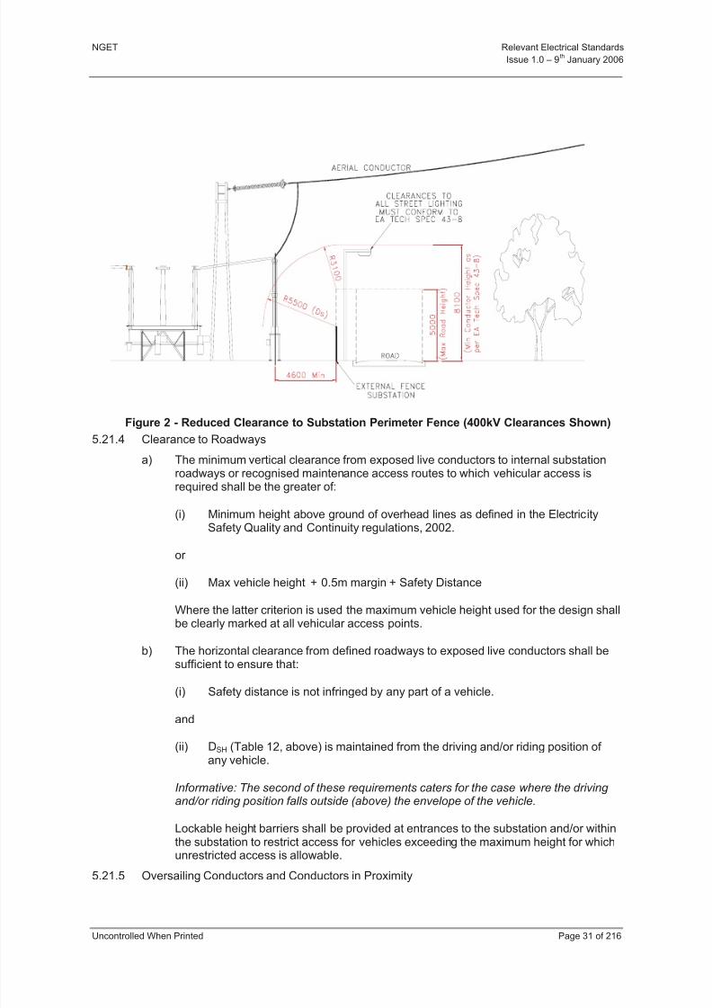
8/3/2019 1 Relevant Standards for Substation Plants
http://slidepdf.com/reader/full/1-relevant-standards-for-substation-plants 38/223
NGET Relevant Electrical Standards
Issue 1.0 – 9th
January 2006
Uncontrolled When Printed Page 31 of 216
Figure 2 - Reduced Clearance to Substation Perimeter Fence (400kV Clearances Shown)
5.21.4 Clearance to Roadways
a) The minimum vertical clearance from exposed live conductors to internal substationroadways or recognised maintenance access routes to which vehicular access isrequired shall be the greater of:
(i) Minimum height above ground of overhead lines as defined in the ElectricitySafety Quality and Continuity regulations, 2002.
or
(ii) Max vehicle height + 0.5m margin + Safety Distance
Where the latter criterion is used the maximum vehicle height used for the design shallbe clearly marked at all vehicular access points.
b) The horizontal clearance from defined roadways to exposed live conductors shall besufficient to ensure that:
(i) Safety distance is not infringed by any part of a vehicle.
and
(ii) DSH (Table 12, above) is maintained from the driving and/or riding position of any vehicle.
Informative: The second of these requirements caters for the case where the driving and/or riding position falls outside (above) the envelope of the vehicle.
Lockable height barriers shall be provided at entrances to the substation and/or withinthe substation to restrict access for vehicles exceeding the maximum height for whichunrestricted access is allowable.
5.21.5 Oversailing Conductors and Conductors in Proximity

8/3/2019 1 Relevant Standards for Substation Plants
http://slidepdf.com/reader/full/1-relevant-standards-for-substation-plants 39/223
NGET Relevant Electrical Standards
Issue 1.0 – 9th
January 2006
Uncontrolled When Printed Page 32 of 216
Informative: Designers are obliged to comply with all relevant health and safety legislation, particularly the designers’ duties under the Construction (Design and Management)Regulations 1994 (CDM). In applying the principles of prevention and protection in thereduction of risk designers’ considerations particular attention is drawn to the hazards of working in proximity to exposed live HV conductors (including 'oversailing' conductors)during construction, operation, maintenance, repair, replacement or demolition of
electrical/mechanical equipment and civil structures.
If the designer does not eliminate hazards presented by exposed live HV conductors fromthe design, there is an obligation on said designer to demonstrate, by risk assessment, that the design has complied with the principles of prevention and protection, as required by CDM. The hierarchy of risk control should be considered when selecting alternative control measures.
Oversailing conductors shall be eliminated from the design as far as is reasonablypracticable.
Informative: Oversailing conductors are exposed HV conductors above or in proximity to any reasonably foreseeable work area and which would normally remain energised during suchwork activities..
Conductors in proximity shall be eliminated from the design.
Informative: Conductors in proximity are exposed HV conductors with insufficient clearanceto a reasonably foreseeable work area to avoid danger and which would normally remainenergised during work activities.
Situations where work activities must be carried out above exposed HV conductors that arelive shall be eliminated from the design.
5.21.6 Substation Profile
The height of the highest component of outdoor substations should be kept to a practicalminimum to achieve a low substation profile.
On new sites the maximum height of equipment shall not exceed the values listed in Table13.
At existing sites the height of existing equipment shall not be exceeded.
Nominal System Voltage (kV) Maximum Equipment Height (m)
132 7.5
275 10
400 12.5
Table 13 - Maximum Equipment Heights in Substations
5.21.7 Earthing Devices
Substations shall have sufficient earthing provision to enable the safe maintenance of anyitem of primary equipment including fixed earthing switches. In particular, it shall be possiblealways to apply an earth between the point of work and all potential fault infeeds.
As a minimum, earthing switches in accordance with Part 4, Section 10 shall be provided atcircuit entries ('line' earth switches) and at one position on each section of busbar.
Line earth switches shall be power operated.
Sufficient earthing devices shall be installed such that the “9 metre rule” for AIS and the“30 metre rule” for GIS, as defined in NGET’s Safety Rules, can be complied with.

8/3/2019 1 Relevant Standards for Substation Plants
http://slidepdf.com/reader/full/1-relevant-standards-for-substation-plants 40/223
NGET Relevant Electrical Standards
Issue 1.0 – 9th
January 2006
Uncontrolled When Printed Page 33 of 216
Further earthing provision may be by means of other types of interlocked earthing devicewhich meet the specified rating.
5.21.8 Portable Earthing
Provision shall be made to employ NGET’s standard portable earthing equipment.
Informative: This equipment is designed for use with tubular conductors with diameters in therange 10-90 mm, 127 mm, 140 mm or 190/200 mm.
Where flexible conductors are used as substation conductors or where tube sizes areincompatible with the existing earthing equipment then earthing stubs shall be provided.
Points for attachment of the earth end of portable earthing leads shall be provided at eachswitchgear structure.
Each portable earthing lead attachment point shall be connected to the substation earthingmat by a fully rated conductor system.
Allowance shall be made for the attachment of sufficient leads at each attachment point tomatch the switchgear rating
For primary earthing NGET require fully rated earthing capability to be applied in a singleoperation. Where primary earthing is to be achieved using portable earthing leads,consideration should be given to safe application positions and compliance with the ManualHandling Regulations.
5.22 GENERAL REQUIREMENTS SPECIFIC TO GIS SUBSTATIONS
5.22.1 Buildings
GIS installations comprising two or more circuit breakers shall be housed in a building. Thebuilding shall be of minimum life cycle cost construction consistent with environmental and
planning requirements.
Fixed crane(s) shall be provided in indoor GIS substations unless the supplier candemonstrate that they are not required for dismantling or removing any part of the substationfor maintenance or repair purposes.
5.22.2 AIS Connections
AIS connections associated with GIS substations shall meet the requirements of detailed inGeneral Requirements Specific to AIS Substations, above.
Line earth switches shall be of AIS design where reasonably practicable.
5.22.3 Portable Maintenance Earthing Devices (PMEDs)
Two three-phase sets of each type of PMED employed shall be supplied.
5.22.4 Gas service connections
A diagram of the gas system shall be displayed at the Local Control Cabinet or at any pointwhere gas service connections are grouped together.

8/3/2019 1 Relevant Standards for Substation Plants
http://slidepdf.com/reader/full/1-relevant-standards-for-substation-plants 41/223
NGET Relevant Electrical Standards
Issue 1.0 – 9th
January 2006
Uncontrolled When Printed Page 34 of 216
5.22.5 Pressure/Density Indication
All displays of pressure/density shall be readable from the substation floor level or fromaccess walkways.
5.22.6 SF6 Gas Alarm Scheme
An audible alarm scheme to warn operators of a major loss of SF6 gas shall be provided inindoor substations. This shall operate at the low pressure alarm setting of each gas zone.
Controls shall be provided at the substation control point to reset and isolate the audiblealarm.
Visual indication(s) shall be provided in the switchhouse to show that the audible alarm is inservice.
Visual indication(s) shall be provided outside the main entrances to the switchhouse toindicate that the alarm has operated.
Consideration should be given to the installation of SF6 detection and alarms in substations
where a slow leak may foreseeably result build up of gas e.g. in basement areas.
5.22.7 Location of Light Current Equipment
Equipment panels may be located in the switchgear building either adjacent to theswitchgear or in an annexe. Such equipment, together with its accommodation, shall meetthe requirements of Class IP 54 of BS EN 60529.
5.23 PERFORMANCE REQUIREMENTS FOR ALL SWITCHGEAR
5.23.1 Jointing of Current Carrying Conductors
Guidance is presented in the Guidance Notes of this Relevant Electric Standard.
5.23.2 Primary Equipment
Calculations or tests shall be performed to demonstrate the mechanical capability of terminals for specified loading combinations of the conductor system in which the equipmentis to be applied.
5.24 ROUTINE TESTS AT SITE
5.24.1 Current Carrying Conductors
Where joints between current carrying conductors are made on site then the joint electricalresistance shall be measured and recorded.
5.25 REFERENCES
BS EN 60694 Common specifications for high-voltage switchgear andcontrolgear standards
BS EN 60865-1 Short-circuit currents. Calculation of effects. Definitions andcalculation methods
BS EN 60529 Specification for degrees of protection provided by enclosures (IPcode).
BS EN 60335-2-76 Specification for safety of household and similar electricalappliances. Particular requirements for electric fence energisers.
BS 1710 Specification for Identification of Pipelines and Services.
BS 5395 Stairs, ladders & walkways.
8/3/2019 1 Relevant Standards for Substation Plants
http://slidepdf.com/reader/full/1-relevant-standards-for-substation-plants 42/223
NGET Relevant Electrical Standards
Issue 1.0 – 9th
January 2006
Uncontrolled When Printed Page 35 of 216
BS 7671 Requirements for electrical installations. IEE Wiring Regulations.Sixteenth edition.
HS(G)38 Lighting at Work
NGET Safety Rules
The Horlock Rules NGC substations and the environment :Guidelines on siting anddesign.

8/3/2019 1 Relevant Standards for Substation Plants
http://slidepdf.com/reader/full/1-relevant-standards-for-substation-plants 43/223
NGET Relevant Electrical Standards
Issue 1.0 – 9th
January 2006
Uncontrolled When Printed Page 36 of 216
5.26 GUIDANCE NOTE - CURRENT TRANSFORMER (CT) ACCOMMODATION
(This Guidance Note does not form part of the RES document)
5.26.1 Integrated Digital Protection/Control
The requirements specified in sections 5.26.2 to 5.26.6 of this Appendix are applicable tosubstations where conventional protection & control equipment is installed.
The introduction of integrated digital protection & control equipment has eliminated therequirement to provide separate CT cores for busbar and feeder protections and tosegregate metering functions from protection. There is still, however, a requirement tomaintain two independent measurement and communication systems for analogue data.
The minimum provision shall be:
a) Two independent current sensors per phase on each circuit. These shall be designed
and constructed in such a way that the risk of common mode failure is, as far asreasonably practicable, minimised.
b) Two independent communication channels for transmitting analogue data to protectionand control equipment. These shall be designed and constructed in such a way thatthe risk of common mode failure is, as far as is reasonably practicable, minimised.
c) Where the measurement or transmission of analogue data is dependent on anauxiliary power supply then each sensor/communications channel shall be suppliedfrom an independent source (e.g. 110V DC supplies 1 and 2).
d) Where transmission of analogue data relies on the operation of active components toprocess this data (e.g. integrators, A/D converters, opto-electric converters) thenfacilities shall be provided for protection relays to use a secondary data source in theevent of failure of the primary source. Typically, relays using data channel 1 wouldrevert to data channel 2 in the event of failure and vice versa.
e) In designing the changeover system, the following hierarchy of preference shall beconsidered (most preferred first, least preferred last):
(i) Automatic changeover on failure of primary data channel.
(ii) Manual changeover by unskilled staff on failure of primary data channel.
(iii) Manual changeover by skilled staff on failure of primary data channel.
f) Changeover facilities shall be designed so that, as far as is reasonably practicable,they do not introduce any additional risks of common mode failure.
5.26.2 Current Transformer Mounting and Polarity Requirements
The following conventions shall be adopted for the physical mounting of current transformerswith respect to their terminal markings:
a) For CT’s which are integral to circuit-breakers and for separately mounted CT’s whichare directly associated with circuit-breakers all P1 markings shall be electrically nearer to the circuit-breaker than the corresponding P2 markings.
b) For CT’s which are integral to transformers, reactors or generators the P1 markings
shall be electrically nearer to the windings than the corresponding P2 markings.

8/3/2019 1 Relevant Standards for Substation Plants
http://slidepdf.com/reader/full/1-relevant-standards-for-substation-plants 44/223
NGET Relevant Electrical Standards
Issue 1.0 – 9th
January 2006
Uncontrolled When Printed Page 37 of 216
c) For separately mounted current transformers which are not associated with the circuit-breakers the P1 markings shall be electrically nearer to the junction of the primaryconnections or busbars than the corresponding P2 markings.
d) In the run of busbars, and not associated with a circuit-breaker, the currenttransformers will usually be in the same housing or chamber. In this case the P1marking should be electrically nearer the section of busbars with the higher number. If there are two housings or chambers (per phase) the P1 markings of each shall beelectrically nearer the adjacent housing or chamber.
The current transformer accommodation normally available for use is as detailed in 5.26.3 to5.26.6 below. In each case the current transformer cores are listed in the preferred order with the housing, core 1 being positioned nearest to the P1 terminal.
5.26.3 Post Type Current Transformers and Through Wall Air/Air BushingsAll 420, 300 and 145 kV post type measurement/protection CTs and through wall air/air bushings shall have accommodation for the arrangements listed belowThe following 'standard' configurations of CT cores are commonly used by NGET.Alternative configurations may be accepted or specified on a contract basis:
a) Five Core Arrangement
A full complement of five secondary windings as follows:
Core 1 Protection Type A
Core 2 Protection Type A
Core 3 Measurement/Protection
Core 4 Protection Type B
Core 5 Protection Type B
This arrangement will be required where older types of high-burdenprotection/instrumentation are installed.
b) Four-Core Arrangement
A complement of four secondary windings as follows:
Core 1 Protection Type A
Core 2 Protection Type A
Core 3 Measurement/Protection
Core 4 Protection Type B
This is the preferred arrangement for circuit CT’s in new substations with digitalprotection/instrumentation systems.
5.26.4 AIS Dead-Tank and Gis Circuit-Breakers
Circuit-breaker bushings, bushing turrets or CT enclosures on the line side of the circuit-breaker shall be capable of accommodating four or five secondary windings in arrangements5.26.3 a) or 5.26.3 b), as required by the application. For busbar coupler and sectionapplications CT accommodation shall be provided on each side of the circuit-breaker.
5.26.5 GIS Back Parts

8/3/2019 1 Relevant Standards for Substation Plants
http://slidepdf.com/reader/full/1-relevant-standards-for-substation-plants 45/223
NGET Relevant Electrical Standards
Issue 1.0 – 9th
January 2006
Uncontrolled When Printed Page 38 of 216
In switchgear making up a mesh or single switch substation additional accommodation isrequired for four or five current transformers in each feeder circuit connection, thearrangement being as 5.26.3 a) or 5.26.3 b).
5.26.6 Slip-Over, Neutral and Other Separately Mounted Current Transformers
Accommodation requirements for such applications are to be examined individually toestablish that sufficient accommodation exists for the current transformer types required.

8/3/2019 1 Relevant Standards for Substation Plants
http://slidepdf.com/reader/full/1-relevant-standards-for-substation-plants 46/223
NGET Relevant Electrical Standards
Issue 1.0 – 9th
January 2006
Uncontrolled When Printed Page 39 of 216
5.27 GUIDANCE NOTE - LOCATION OF CURRENT TRANSFORMERS ASSOCIATED WITH420, 300 AND 145 KV CIRCUIT BREAKERS
(This Guidance Note does not form part of the RES document)
5.27.1 General
In all installations where current transformer housings are associated with circuit-breakerssuch housings shall be mounted as close as possible to the circuit-breaker concerned.
5.27.2 Busbar Stations
Circuits Other than Bus Section or Bus Coupler - All current transformers associated with agiven circuit-breaker shall be installed on the circuit side of the circuit-breaker.
5.27.3 Mesh Type Stations
Current transformers for feeder protection, feeder instrumentation purposes and for systemback-up protection shall be installed in the line current transformer housing.
Current transformers for bus section instrumentation purposes and circuit-breaker failprotection shall be installed in the bushings or housings on the side of the circuit-breaker which connects to the mesh corner having the corresponding number e.g. mesh corner four side of S40 etc.
Current transformers for mesh-corner protection shall be installed in the line currenttransformer housing, in the HV bushing turrets of the associated transformer(s) and on bothsides of the circuit breakers. The current transformer for a particular zone of protection shallbe located on the side of the circuit breaker remote from that zone.
5.27.4 Single Switch Stations
Current transformers for feeder protection and for feeder instrumentation purposes shall be
installed in the line current transformer housings.
Current transformers for system back-up protection shall be installed in the line currenttransformer housings and in the bushings or housings on the higher numbered side of thebus section circuit-breaker. The current transformer for system back-up protection shall alsobe used for circuit-breaker fail protection.
Current transformers for bus section instrumentation purposes shall be installed in thebushing or housings on the lower numbered zone side of the bus section circuit-breaker.
Current transformers for mesh corner protection shall be installed in the line currenttransformer housings, the HV bushing turrets of the associated transformer(s) and in thebushings or housings on both sides of the bus section circuit-breaker. The currenttransformer for a particular zone or protection shall be located on the side of the circuit-breaker remote from that zone.
8/3/2019 1 Relevant Standards for Substation Plants
http://slidepdf.com/reader/full/1-relevant-standards-for-substation-plants 47/223

8/3/2019 1 Relevant Standards for Substation Plants
http://slidepdf.com/reader/full/1-relevant-standards-for-substation-plants 48/223
NGET Relevant Electrical Standards
Issue 1.0 – 9th
January 2006
Uncontrolled When Printed Page 41 of 216
6.2.3 Operating Mechanisms, Ancillary Equipment and their Enclosures
The local control and monitoring apparatus shall be accommodated at the switchgear whichit controls (This is termed the local control point). Such accommodation shall be clearlylabelled to indicate the apparatus it contains and the switchgear controlled.
The local control point shall be located at ground (floor/fixed access) level.
Indication of the operational position of the switchgear being controlled shall beunambiguous and clearly visible from ground (floor/fixed access) level.
Switchgear with power operated mechanisms shall be provided with means of initiation of closing and opening, and selection of local/remote control, at the local control point.
Three phase switching devices with separate phase mechanisms shall be controllable from asingle point, the local control point.
The supplier shall clearly state the maximum available number of auxiliary switches and thenumber normally pre-allocated for use within the switchgear itself.
Auxiliary switches shall be positively driven in both directions.
Where anti-condensation heaters are fitted in cubicles of switchgear, they shall be physicallyand electrically shrouded to protect operators of the switchgear from danger.
6.2.4 Sulphur Hexafluoride Gas (SF6)
New SF6 gas shall conform to IEC 60376.
Recycled SF6 gas shall conform to IEC 60480 and Appendix A of this document.
At the time of commissioning of switchgear containing SF6 gas, the gas shall have a
moisture content of no greater than 25 mg/kg (approximately -35C dew point at atmosphericpressure).
NGET reserves the right to require reprocessing where the differential between the moisturecontent of the filling gas and final moisture content is greater than 10 mg/kg (approximately a
5C dew point change).
6.3 PERFORMANCE REQUIREMENTS
6.3.1 Gaseous Insulation
The Supplier shall state the minimum density of the gaseous insulating medium at whichcircuit breakers and disconnectors can withstand two fully asynchronous power frequencyvoltages applied to the opposite terminals of the same pole when in the OPEN position.
Each voltage to be equal to the rated phase to earth power frequency voltage.
The Supplier shall state the density of the gaseous insulating medium at which all gasinsulated equipment can withstand 1.5 times the rated phase to earth power frequencyvoltage between its conducting parts and earth and where appropriate between phases.
Means shall be provided to enable gas systems to be safely replenished whilst theequipment is in service.
8/3/2019 1 Relevant Standards for Substation Plants
http://slidepdf.com/reader/full/1-relevant-standards-for-substation-plants 49/223
NGET Relevant Electrical Standards
Issue 1.0 – 9th
January 2006
Uncontrolled When Printed Page 42 of 216
6.3.2 Rated Voltage of Closing and Opening Releases and Operating Devices
a) Direct Current Systems
The rated supply voltage of the dc system at NGET substations is 125 V. Closing andOpening releases and operating devices shall operate over the voltage ranges,
measured at their terminals, given in Table 14.
The Supplier shall declare the characteristics of the current required by the closingand opening releases and operating devices when operating at the minimumoperating voltage.
Closing and OpeningReleases and
Operating Devicesdc System
Close Open
Maximum Operating Voltage Volts 137.5 137.5 137.5
Minimum Operating Voltage Volts 93.5 87.5 77
Table 14 - Rated Supply and Operating Voltage Range for dc Systems andOperating Devices
b) Alternating Current Systems
Alternating current control systems are not acceptable for the control of circuit-breakers, switches, disconnectors or earthing switches.
6.4 TEST REQUIREMENTS FOR SWITCHGEAR
6.4.1 Dielectric Tests
a) Gas Insulated Switchgear (GIS)
Dielectric tests shall be to the requirements of IEC 60694. Where doubt existsregarding the path of any breakdown during testing it shall be assumed that thebreakdown involved non-self restoring insulation.
b) Atmospheric Air Insulated Switchgear (AIS)
Dielectric tests shall be to the requirements of IEC 60694. Where doubt existsregarding the path of any breakdown during testing it shall be assumed that thebreakdown involved non-self restoring insulation.
6.4.2 Mechanical Strength of Hollow Ceramic and Composite Pressurised Insulation
Ceramic hollow support pressurised insulation shall be designed and tested according to
IEC 61264 for pressure and bending stresses.
The Supplier shall state the type test withstand bending moment, routine test bendingmoment and the bending moment equivalent to the design pressure. In addition the Supplier shall state the bending moment, above that required to satisfy the total loading requirementsof the switchgear itself, which is available for the connections to adjacent switchgear.
Informative: The total loading requirement includes consideration of the 100% wind pressurewithout ice accretion, 100% short-circuit forces, equipment internal pressure, equipment mass and mechanical operation.
8/3/2019 1 Relevant Standards for Substation Plants
http://slidepdf.com/reader/full/1-relevant-standards-for-substation-plants 50/223
NGET Relevant Electrical Standards
Issue 1.0 – 9th
January 2006
Uncontrolled When Printed Page 43 of 216
Hollow composite insulation for unpressurised and pressurised applications shall bedesigned and tested according to the rules prescribed in IEC. The Supplier shall self-certificate that the insulator materials and insulator design satisfy the design test criteria IEC61462.
The supplier shall state the following insulator mechanical cantilever and internal pressureloads:
a) Cantilever
Maximum mechanical load (MML), i.e., the equipment design load; the routinecantilever bending load; the damage limit; the type test cantilever bending load andthe specified mechanical load (SML).
b) Internal Pressure
Maximum service pressure (MSP), i.e., the equipment design pressure; the routinetest pressure; the damage limit; the type test pressure and the specified internal
pressure (SIP).
The Supplier shall self certificate the compliance of the routine tests with Clause 10 of IEC 61462.
In addition the Supplier shall state the cantilever bending load, above that required to satisfythe total loading requirements of the switchgear itself, which is available for the connectionsto adjacent switchgear. The total loading requirement includes consideration of the 100%wind pressure without ice accretion, 100% short circuit forces, equipment internal pressure,equipment mass and mechanical operation.
6.4.3 Routine Tests
Routine Tests shall normally be performed at the point of manufacture.
Commissioning tests and routine tests that are performed at site shall be fully documented.
Power-operated switchgear shall be operated mechanically 50 times with each operationinitiated as per in service operation.
Informative: This number may include routine tests.
Commissioning procedures and acceptance values shall be detailed by the Supplier.
Diagnostic tests shall be incorporated into the commissioning test programme and beperformed on all equipment to establish its correct operation.
Informative: Such tests may include, but are not restricted to, the measurement of operating coil currents, contact timing, speed of operation, travel characteristics, contact engagement,synchronous operation of poles, primary circuit resistance, checks for gas and liquid leakage, checks for the correct operation of monitoring devices and checks on the quality of the insulating and arc- quenching media.

8/3/2019 1 Relevant Standards for Substation Plants
http://slidepdf.com/reader/full/1-relevant-standards-for-substation-plants 51/223
NGET Relevant Electrical Standards
Issue 1.0 – 9th
January 2006
Uncontrolled When Printed Page 44 of 216
6.5 REFERENCES
6.5.1 International, European and British Documents
This Specification makes reference to the documents listed below.
BS EN 60694 Common Specifications for High Voltage Switchgear and Controlgear Standards
BS 1710 Specification for Identification of Pipelines and Services
IEC 60376 Specification for Sulphur Hexaflouride for Electrical Equipment
IEC 61264 Ceramic Pressurised Hollow Insulators for High-Voltage Switchgear andControlgear.
IEC 61462 Composite Insulators for use in Outdoor and Indoor Electrical Equipment.
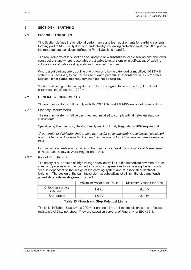
8/3/2019 1 Relevant Standards for Substation Plants
http://slidepdf.com/reader/full/1-relevant-standards-for-substation-plants 52/223
NGET Relevant Electrical Standards
Issue 1.0 – 9th
January 2006
Uncontrolled When Printed Page 45 of 216
7 SECTION 4 - EARTHING
7.1 PURPOSE AND SCOPE
This Section defines the functional performance and test requirements for earthing systems
forming part of NGET’s System and protected by fast acting protection systems*
. It supportsthe more general conditions defined in Part 4 Sections 1 and 2.
The requirements of this Section shall apply to new substations, cable sealing end and tower constructions and where reasonably practicable to extensions or modifications of existingsubstations and cable sealing ends and tower refurbishment.
Where a substation, cable sealing end or tower is being extended or modified, NGET willstate if it is necessary to control the rise of earth potential in accordance with 7.2.2 of thisSection. If not stated, this requirement need not be applied.
*Note: Fast acting protection systems are those designed to achieve a target total faultclearance time of less than 200 ms.
7.2 GENERAL REQUIREMENTS
The earthing system shall comply with EA TS 41-24 and BS 7430, unless otherwise stated.
7.2.1 Statutory Requirements
The earthing system shall be designed and installed to comply with all relevant statutoryinstruments.
Specifically, The Electricity Safety, Quality and Continuity Regulations 2002 require that:
“A generator or distributor shall ensure that, so far as is reasonably practicable, his network does not become disconnected from earth in the event of any foreseeable current due to afault”.
Further requirements are contained in the Electricity at Work Regulations and Managementof Health and Safety at Work Regulations 1999.
7.2.2 Rise of Earth Potential
The safety of all persons on high voltage sites, as well as in the immediate environs of suchsites, and persons who may contact any conducting services to, or passing through suchsites, is dependent on the design of the earthing system and its associated electricalisolation. The design of the earthing system at substations shall limit the step and touchpotentials to safe levels given in Table 15.
Maximum Voltage for Touch Maximum Voltage for Step
Chippings surface(150 mm)
1.4 kV 4.6 kV
Soil surface 1.0 kV 3.1 kV
Table 15 - Touch and Step Potential Limits
The limits in Table 15 assume a 200 ms clearance time, a 1 m step distance and a footwear
resistance of 2 k per shoe. They are based on curve c1 of Figure 14 of IEC 479-1.
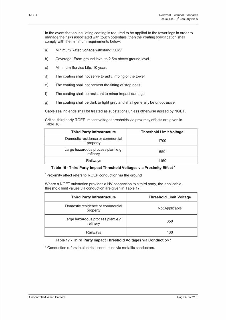
8/3/2019 1 Relevant Standards for Substation Plants
http://slidepdf.com/reader/full/1-relevant-standards-for-substation-plants 53/223
NGET Relevant Electrical Standards
Issue 1.0 – 9th
January 2006
Uncontrolled When Printed Page 46 of 216
In the event that an insulating coating is required to be applied to the tower legs in order tomanage the risks associated with touch potentials, then the coating specification shallcomply with the minimum requirements below:
a) Minimum Rated voltage withstand: 50kV
b) Coverage: From ground level to 2.5m above ground level
c) Minimum Service Life: 10 years
d) The coating shall not serve to aid climbing of the tower
e) The coating shall not prevent the fitting of step bolts
f) The coating shall be resistant to minor impact damage
g) The coating shall be dark or light grey and shall generally be unobtrusive
Cable sealing ends shall be treated as substations unless otherwise agreed by NGET.
Critical third party ROEP impact voltage thresholds via proximity effects are given inTable 16.
Third Party Infrastructure Threshold Limit Voltage
Domestic residence or commercialproperty
1700
Large hazardous process plant e.g.refinery
650
Railways 1150
Table 16 - Third Party Impact Threshold Voltages via Proximity Effect *
*Proximity effect refers to ROEP conduction via the ground
Where a NGET substation provides a HV connection to a third party, the applicablethreshold limit values via conduction are given in Table 17.
Third Party Infrastructure Threshold Limit Voltage
Domestic residence or commercialproperty
Not Applicable
Large hazardous process plant e.g.refinery 650
Railways 430
Table 17 - Third Party Impact Threshold Voltages via Conduction *
* Conduction refers to electrical conduction via metallic conductors.

8/3/2019 1 Relevant Standards for Substation Plants
http://slidepdf.com/reader/full/1-relevant-standards-for-substation-plants 54/223
NGET Relevant Electrical Standards
Issue 1.0 – 9th
January 2006
Uncontrolled When Printed Page 47 of 216
The design of the earth electrode system (whether this is as a result of adding to an existingsystem or the installation of new system), shall be optimised in so far as is reasonablypractical to ensure third party impact threshold voltages are within the limits in Tables 16 and17. In particular, consideration shall be given to the arrangement of the electrode systemand the use of all land within the substation boundary. It is only necessary to use land
outside the substation boundary (within NGET’s ownership) if stated by NGET. The earthelectrode depth and geometry shall be optimised to make use, as far as practicable, of lower resistivity ground strata.
Where reasonably practicable, the earthing system shall be designed using an earth returncurrent which is 20% greater than that calculated by NGET, to allow for future increases insystem fault current.
Calculations to design the main earth system shall be carried out using CDEGS softwarepackage (Current Distribution, Electromagnetic Fields, Grounding and Soil StructureAnalysis). The design models produced shall be made available once completed andbecomes the property of NGET as part of the connection agreement.
Communication cables connecting to all NGET substations must be fitted with appropriateelectrical isolation.
7.2.3 Earth Electrodes
Earth electrodes shall be designed to operate satisfactorily during faults, taking into accountthe area of the electrodes in contact with earth, the soil resistivity and earth electrode currentmagnitude and duration, in accordance with BS7430. The fault duration times to be used for rating the electrodes are 1 second for 275 kV and 400 kV and 3 seconds for all other voltages.
Buried bare copper horizontal earth electrodes shall be installed at around 500 mm depth. If the indigenous soil is hostile to copper, see clause 7.4.1 b), the electrode shall besurrounded by 150 mm of non-corrosive soil of fine texture, firmly rammed. Where there is a
likelihood of soil migration and leaching, alternative materials may be used as described inBS 7430. Conductors installed in ploughed farmland shall be buried at least 1 m deep, at allpoints, measured from undisturbed ground level.
Where horizontal earthing conductors are exposed to indigenous soils that are hostile tocopper, stranded copper conductors are not permitted within the earthing design.
Driven rod electrodes in accordance with EA TS 43-94 shall be used to exploit lower resistivity ground strata where present to reduce the site rise of earth potential in accordancewith 7.2.2. Where the ground is hard and rods cannot be driven, consideration shall begiven to drilling holes to install the rods and back filling with a suitable low resistance fillmaterial.
Buried conductors and electrodes shall be at least 3 m away from buried cables withuncovered metallic sheaths, unless the sheaths are used as part of the earthing system.
Where beneficial, reinforcing steelwork incorporated within piling shall be utilised as an earthelectrode. However, care must be taken to ensure that the current carrying capacity of thesteelwork is not exceeded. Connections shall be made to each vertically steel bar within thepile cap. Connections brought out through the pile cap shall be provided with appropriatemeans to prevent moisture ingress into the cap. Current carrying connections to and withinthe steelwork shall be in accordance with Part 4, Section 2. Fortuitous connections must notbe relied upon.
Where sheet steel piles of the interlocking kind are used as an earth electrode, connections
shall be made to each pile.

8/3/2019 1 Relevant Standards for Substation Plants
http://slidepdf.com/reader/full/1-relevant-standards-for-substation-plants 55/223
NGET Relevant Electrical Standards
Issue 1.0 – 9th
January 2006
Uncontrolled When Printed Page 48 of 216
7.2.4 Earth Electrode Arrangement
Unless otherwise agreed by NGET, the earthing electrode arrangement shall be based on aperipheral buried main bare earthing conductor generally encompassing the plant items tobe earthed, with buried spur connections, from the main conductor to the items of plant. Themain earthing conductor shall be augmented with inter-connected buried bare cross-
connections to form a grid. In addition, where beneficial, groups of earth rods distributedaround the periphery shall be connected to this main earthing conductor.
For indoor substations the earthing grid shall be installed with spur connections to the steelreinforcing mat of the concrete floor, every 20 m. Additionally, a second peripheral mainearthing conductor shall be buried at 1 m distance from the building, which shall be bondedto the first main conductor, and to the building if it is metalclad, both at 20 m intervals. Earthrod groups shall be connected to the second peripheral conductor as previously described inin the paragraph above.
7.2.5 Test Facilities
In order to facilitate testing of all earth electrode groups, a section of conductor connecting toeach group shall be made accessible and shall have dimensions that would fit inside 25 mm
diameter circular clamp meter jaws (min length 75 mm). An example of how this can beachieved is shown in 7.10, figure 8 of this Section. This section of conductor shall be a partof a spur connection to the rod group ie so that all the test current flows into the rod groupand is not diverted into the main earth system.
Disconnectable links must not be fitted in the connections from the main earth system toterminal towers or rod groups or in the connections between main earth systems, e.g.between earth systems on joint sites.
7.2.6 More Than One HV Substation
Where there is more than one NGET substation on the same site a separate earth grid shallenclose each substation and these grids shall be connected together at the extremities by atleast two fully rated conductors ideally taking secure separate physical routes. In order to
facilitate testing of the interconnections, the conductors connecting the systems together shall each be made accessible at a designated point. At this point the conductors shall havedimensions which would fit inside a 25 mm diameter circular clamp meter jaws (min length of conductor 75 mm). An example of how this can be achieved is shown in 7.10, figure 6 of thisSection.
Where a NGET substation is located on the same site as another users substation, theearthing systems shall be interconnected as defined by NGET.
Measures shall be taken to ensure that persons can not come into contact with hazardoustransferred potentials between substations or directly connected customers, particularlywhere sites are separated. Where control of these potentials requires measures to be takenby a third party, NGET shall be informed by the supplier at the time of production of the
earthing design.
In all cases where HV earthing systems are connected together, disconnectable test linksshall not be fitted.
8/3/2019 1 Relevant Standards for Substation Plants
http://slidepdf.com/reader/full/1-relevant-standards-for-substation-plants 56/223
NGET Relevant Electrical Standards
Issue 1.0 – 9th
January 2006
Uncontrolled When Printed Page 49 of 216
7.2.7 Equipment Connected to the Main earth system
The following items of equipment shall be connected to the main earth system by a fullyrated conductor:
a) All points which may form the earth of a high voltage fault path.
b) Transformer winding neutrals required for HV system earthing. For 66 kV and below,the connection may be via earthing resistors or other current limiting devices.
c) In the case of a manually operated earthing or HV switch, a dedicated fully ratedconductor shall be run from the handle or mechanism box to the main earth system asdirectly as possible and this conductor shall pass under the stance position of theperson operating the switch. The conductor runs to any fault points associated withthe switch shall, where practicable, be maintained separate from the handle or mechanism of the switch and connecting metalwork.
All metalwork e.g. panels, cubicles, kiosks etc, including the steelwork of buildings, shall bebonded to the main earth system by a conductor of no less than 70 mm
2cross section. Strip
conductor shall be no less than 3 mm thick.
Mechanical linkages, e.g. turnbuckles, shackles etc, which could form part of the earthconnection shall be shunted across using fully rated flexible conductor to prevent damage bythe passage of fault current.
Metallic trench covers shall be earthed to cater for the possibility of an earth fault on cablingin the trench and to cater for the possibility of induced or transferred potentials. To achievethis, metal trench covers may be laid on conducting support(s) that shall each be connectedto the main earth system by a conductor as specified above.
7.2.8 Installation
Earth conductors in trenches containing power and/or multicore cables shall be fixed to the
walls approximately 100 mm from the top to maintain separation from the cables.
Due regard shall be given to the possibility of mechanical damage to buried conductors and,where necessary, either marker tapes and/or mechanical protection shall be installed. Aseparation of at least 500 mm to civil works such as drainage pits, shall be maintained.Conductor runs above ground shall be designed to minimise the possibility of mechanicaldamage.
When laying stranded conductors, care shall be taken to avoid distorting individual strands.
Conductors shall be fixed firmly and tidily to structures at a spacing of no more than 1 m.The fixings shall not allow galvanic corrosion to occur and shall not require the conductor tobe drilled unless otherwise agreed by NGET.
Where earth conductors cross they shall be jointed (other than in the case of rod groupswhere these must be maintained separate to permit testing).
Where earth conductors connect to equipment the connections shall as far as practicable bemade onto vertical surfaces only. Connections to the metal cladding of buildings shall beinside the building.
Aluminium conductor shall only be installed at least 250 mm above ground level.
All conductor joints shall be in accordance with the Guidance Notes given in this RelevantElectrical Standards document.
Where specified, buried earth tape shall be protected from theft by measures such asconcrete anchors or securing to driven earth rods.

8/3/2019 1 Relevant Standards for Substation Plants
http://slidepdf.com/reader/full/1-relevant-standards-for-substation-plants 57/223
NGET Relevant Electrical Standards
Issue 1.0 – 9th
January 2006
Uncontrolled When Printed Page 50 of 216
Bolted joints are not acceptable below ground other than for earth rod screw couplings whichshall be thoroughly greased. Connections to buried earth rods shall be welded inaccordance with the Guidance Notes given in this Relevant Electrical Standards document.
7.2.9 Portable Earthing
Loops for portable earths shall be provided on the earthing conductor at each location whereportable earths may be required to be applied. The loops shall be fully rated and suitable for NGET standard portable earthing equipment, and shall be made of copper or aluminium.The loops shall be not less than 230 mm long and shall be 75 mm clear of the earthingconductor. Loops for portable earths shall be installed at a convenient height and shall beseparately formed, ie not by bending the earthing conductor.
The rating of multiple portable earth leads shall be as listed in Table 18
Number of leads (150 mm2
aluminium) Rating
1 17.5 kA
2 31.5 kA
3 47.25 kA
4 63 kA
Table 18 - Ratings for multiple portable earth leads
7.2.10 Steel Support Structures
Where the current carrying capacity of steel support structures is at least equal to theswitchgear rating, it is preferred that the structure is utilised to form part of the connection tothe main earthing system, in which case there is no need to fix an earth conductor along thissection.
Where a steel structure is relied upon to provide an earth connection for supported
equipment, current carrying joints within 2.4 m of ground level shall be in accordance withthe Guidance Notes given in this Relevant Electrical Standards document. Above 2.4 m thenormal structural joints are considered adequate for electrical integrity during faultconditions.
Steel structures shall not be relied upon to conduct high frequency currents or for earthconnections to earth switches.
Where post insulators, other than those forming part of shunt connected equipment (eg CTs,VTs, SAs) are supported by a steel structure the insulator base does not require a bridgingconnection to the structure.
7.2.11 Fences
Measures shall be taken to ensure that dangerous touch or transferred potentials cannotarise on substation fences.
Perimeter fences may be independently earthed using 5 m long rod electrodes inaccordance with BS7430. Alternatively, perimeter fences may be connected to the mainearth system in accordance with BS7430.
Where a perimeter fence is independently earthed, 2m separation must be maintained between the fence and the main earth system and equipment connected to it.
Unless otherwise agreed by NGET, where a perimeter fence is connected to the main earthsystem an additional buried bare conductor shall be installed 1 m outside the fence buried ata depth of 0.5 m to control touch potentials. This conductor shall be connected to the mainearth system and fence at 50 m min intervals.
8/3/2019 1 Relevant Standards for Substation Plants
http://slidepdf.com/reader/full/1-relevant-standards-for-substation-plants 58/223
NGET Relevant Electrical Standards
Issue 1.0 – 9th
January 2006
Uncontrolled When Printed Page 51 of 216
Internal fences within the curtilage of the main earth system shall be connected to it at 50 mmin intervals and at changes of direction and where power lines cross overhead. Unlessotherwise agreed by NGET, internal fences not within the curtilage of the main earth systemshall have an additional buried bare conductor installed 1m on either side of the fence buriedat a depth of 0.5 m connected to the fence at 50 m intervals to control touch potentials.
Where a fence, which is connected to the main earth system, abuts an independentlyearthed fence they shall be electrically separated using either a non-metallic fence panel or an insulating section having 5 cm (approx) creepage at each end of a 2 m section which isnot connected electrically to either of the fences. A suggested method of installation usinginsulating bushes is shown in 7.10, figure 7 of this Section.
A cable having a metallic covering effectively in contact with the ground or a bare conductor which passes underneath an independently earthed fence shall be covered with insulationfor a distance of 2 m on either side of the fence. For example this may be achieved byrunning the conductor in an alkethene pipe 2 m either side of the fence.
Where galvanised steel chain link internal fencing is used, a separate earth conductor shallbe installed along the fence (min 70 mm2) and shall be connected to each section of fenceevery 10 m or less and to the main earth system at 50 m intervals.
Where plastic coated steel chain link internal fencing is used, connection to the mainearthing system shall be made at all fence guide wire anchor points (min 70 mm2).
Connections to the fence shall be via a conductor which shall be accessible and shall havedimensions which would fit inside 25 mm diameter circular clamp meter jaws. Where bolted joints are used to connect to the fence, these shall be protected with Denso Mastic andTape.
7.2.12 Access/Egress Gates
Access/egress gates are not required to be bonded to its supporting post. Note that this
should not be confused with the requirement to cross bond between gate supporting posts,and that this requirement should still be met.
7.2.13 Temporary Fences
Temporary metallic fences shall be installed with appropriate measures to limit touch or transferred potentials to safe levels.
An internal metallic fence within the curtilage of the main earth system shall be connected tothe main earth system at 50 m intervals, at changes of direction and where power lines crossoverhead.
Where a temporary metallic fence which is connected to the main earth system abuts anindependently earthed fence they shall be electrically separated in accordance with BS7430.
A fence outside the curtilage of the main earth system may present a greater hazard where itcrosses the ground voltage profile. In this case, in order to limit the transferred potential, thefence shall either be non-metallic or shall have its sections electrically insulated from eachother at intervals depending on the ground voltage profile at the site.
8/3/2019 1 Relevant Standards for Substation Plants
http://slidepdf.com/reader/full/1-relevant-standards-for-substation-plants 59/223
NGET Relevant Electrical Standards
Issue 1.0 – 9th
January 2006
Uncontrolled When Printed Page 52 of 216
7.2.14 Terminal Towers
Where the earth wire of an incoming line terminates on a tower it shall be connected to thetop of the tower.
The tower shall be connected to the adjacent substations main earth system (not rod groups)
at two separate points by two spur copper strap conductors following secure separateroutes. The copper strap shall have a cross section no less than 50 mm x 6 mm. Thereshall be no disconnectable links in these connections. These conductors shall be connectedto different legs of the tower and shall be adequately protected to prevent damage and deter theft. Where these conductors cross or come close to rod groups they shall be insulated tomaintain an electrical separation between bare conductors of 2 m min.
Where a terminal tower leg is within 2 m of an independently earthed fence, the affectedsections of fence shall be connected to the tower and insulated sections fitted either side of the affected sections.
7.2.15 LV Distribution Transformers
The earthing and isolation of LV distribution transformers associated with NGET substations
shall be designed assuming that the substation ROEP is greater than 650 V rms.
Where an LV distribution transformer is used to provide LV auxiliary supplies to thesubstation and is supplied externally, the following requirements shall apply:
a) Where the transformer is sited within NGET’s substation, the transformer steelworkand LV neutral shall be connected to the substation main earth system. The incomingHV supply shall be electrically isolated from the main earth system at a minimum levelof 10 kV rms. The HV cable sheath and any metalwork connected to it shall beinsulated at a minimum level of 10 kV rms and the cable termination shall be clearlylabelled to indicate a transferred potential hazard. The transformer must not be usedto provide LV supplies external to NGET’s substation. This arrangement is illustratedin 7.10, figure 4 of this Section.
b) Where the transformer is sited outside NGET’s substation, the transformer LV neutraland LV cable sheath shall be connected to the main earth system and electricallyisolated from the external HV supply, including its associated earth, at a minimumlevel of 10 kV rms. The LV cable sheath insulation shall be rated at10 kV rms min. At the transformer end, the LV cable sheath and any metalworkconnected to it shall be insulated at a minimum level of 10 kV rms and the cabletermination shall be clearly labelled to indicate a transferred potential hazard. Thetransformer must not be used to provide LV supplies external to NGET’s substation.This arrangement is illustrated in 7.10, figure 5 of this Section.
Where an LV distribution transformer, sited within NGET’s substation, is used to provide LVsupplies external to the substation, the following requirements shall apply:
c) The transformer steelwork shall be connected to the main earth system. Thetransformer LV neutral shall be electrically isolated from the main earth system andthe HV winding of the transformer at a minimum level of 10 kV rms. The LV cablesheath and any metalwork connected to it shall be insulated at a minimum level of 10 kV rms and the cable termination shall be clearly labelled to indicate a transferredpotential hazard. This arrangement is illustrated in 7.10, figure 6 of this Section.
8/3/2019 1 Relevant Standards for Substation Plants
http://slidepdf.com/reader/full/1-relevant-standards-for-substation-plants 60/223
NGET Relevant Electrical Standards
Issue 1.0 – 9th
January 2006
Uncontrolled When Printed Page 53 of 216
7.2.16 Gas Insulated Substations
Gas insulated substations with single phase enclosures have specific earthing requirementsto reduce circulating currents in supporting steelwork.
The main earth system shall be well integrated in the regions close to equipment with short
spur connections taken to specific points. Connections to this system, together with directconnections between phases shall be made at all line, cable and transformer terminations, atbusbar terminations and at approximately 20 m intervals in busbar runs. Inter-phaseconnections shall be rated to carry induced currents resulting from the flow of rated normalcurrent in the primary conductors.
7.2.17 Anti-climbing Precautions Along the Tops of Walls
Where barbed wire or other metal anti-climbing devices are erected along the tops of brickwalls etc these shall be connected to earth using the same procedure as with fencing.
7.2.18 Substation Lightning Protection Systems
Where required, lightning protection systems shall be in accordance with BS 6651. Alllightning protection system conductors shall be connected to the substation main earthing
system.
7.2.19 Design Life of Installation
All parts of the earthing installation, both below and above ground, shall have a design life of 40 years taking into account the anticipated corrosion of the conductors resulting from site chemical pollution.
7.3 PERFORMANCE REQUIREMENTS
7.3.1 Conductors
All conductors which may carry fault point current shall be fully rated. Earth conductors shallbe rated so as not to exceed the maximum temperatures given in Table 19. Duplicate or loop connections shall be derated by a minimum of 20% to allow for unequal current sharing.
Type of conductor Maximum recommended conductor temperature during a short circuit
Bare conductors, solid or stranded: Cu 405oC
Bare conductors, solid or stranded: Al or Alalloy
325oC
Bare conductors, solid or stranded: steel 300oC
Table 19 - Highest Temperatures for Non-Mechanically Stressed Conductors During aShort Circuit
7.4 DESIGN INFORMATION
7.4.1 The designer of the earth electrode system should consider the following:
a) The site soil resistivity profile and suitability for driving earth rods (see 7.9 of thisSection for measurement methods).
b) The chemical and/or physical nature of the site soil structure. For example, thepresence of corrosive soils (acids, nitrates, sulphides, sodium silicates, ammoniumchlorides, sulphur dioxides) should be considered in the design of an earthing systemwith a 40 years life design requirement
c) Details of the civil engineering structures existing, or to be built on site shall beascertained to determine if the reinforcing steelwork incorporated within the structuresor piling can be used as an earth electrode.
d) For existing sites, the latest site earthing survey.
8/3/2019 1 Relevant Standards for Substation Plants
http://slidepdf.com/reader/full/1-relevant-standards-for-substation-plants 61/223
NGET Relevant Electrical Standards
Issue 1.0 – 9th
January 2006
Uncontrolled When Printed Page 54 of 216
e) The earth return current and the switchgear rating.
f) Existing third party infrastructure, including future known developments, in the vicinityof the substation.
If available, NGET will provide the supplier with some or all of the above information. Theavailability of this information will be stated in the tender document.
7.5 TEST REQUIREMENTS
Validation by electrical measurement of any design is required for all installed systems toconfirm the satisfactory installation and design of the system. NGET reserves the right towitness all tests. The measurement methods are outlined in 7.9 of this Section.
The resistance to earth of all individual rods and rod groups shall be measured andrecorded. Where the measured resistance of an individual rod is more than 50% higher thanthe average for the site the reason shall be investigated and the rod(s) re-installed if necessary.
The total substation earth electrode impedance shall be measured using the AC Fall of Potential Method and the result recorded. The measured result shall be compared with thatpredicted by calculation and any significant difference investigated. On some sites it maynot be practicable to carry out this measurement due to the surrounding environment and itmay be necessary to rely on calculation alone. In this case, careful attention must be givento establishing accurate data for the calculation, e.g. the soil resistivity profile and the layoutof the main earth system.
For transmission towers, as far as is reasonably practicable, both the footing resistance andthe chain impedance shall be measured.
Tests of all electrical joints shall be made in accordance with the Guidance Notes given in
this Relevant Electrical Standards document.
The supplier, at the request of NGET, may be required to excavate in order to reveal earthconductor joints for testing, or to demonstrate correct installation to drawing.
7.6 ACCEPTANCE PROCEDURE
The supplier shall provide evidence that the tests described in this document have beencarried out satisfactorily.
The supplier shall provide evidence that the necessary precautions have been taken toprevent unsafe touch, step and transferred potentials from arising.
The supplier shall provide documentation to demonstrate that the earthing installationcomplies with this document and includes with it ROEP contour plots showing 430V, 650V,1150V and 1700V contours overlaid onto an OS map (see also 7.2.2 of this Section).
The map accuracy should be checked during site assessment to include all 3rd party properties within the proximity with detail of its occupation.
8/3/2019 1 Relevant Standards for Substation Plants
http://slidepdf.com/reader/full/1-relevant-standards-for-substation-plants 62/223
NGET Relevant Electrical Standards
Issue 1.0 – 9th
January 2006
Uncontrolled When Printed Page 55 of 216
7.7 REFERENCES
This document makes reference to or should be read in conjunction with the documentslisted below:
The Health and Safety at Work Act, 1974.
The Electricity At Work Regulations, 1989.
The Electricity Safety, Quality and Continuity Regulations 2002
Electricity Supply Regulations 1988, Statutory Instrument No 1057.
Electricity Supply (Amendment) Regulations 1990, Statutory Instrument No 390.
The Management of Health and Safety at Work Regulations, 1999.
IEC 479-1 International Electrotechnical Commission, Technical Report, Effects of Current
on Human Beings and Livestock - Part 1 General Aspects.
BS 6651, Code of practice for protection of structures against lightning, 1999
BS 7430 Code of practice for Earthing 1998 (Formerly CP 1013: 1965).
BS 7354 Code of Practice for Design of High Voltage Open Terminal Substations.
EA TS 41 24, Guidelines for the Design, Installation, Testing and Maintenance of MainEarthing Systems in Substations, Issue 1: 1992.
EA S 34 A Guide For Assessing the Rise of Earth Potential at Substation Sites, May 1986.
EA S 36, Procedure to Identify and Record hot Substations, December 1988.
EA TS 43-94 Earth Rods and their Connectors, Issue 3, 1990.
ITU-T K.33 Limits for people safety related to coupling into telecommunications system froma.c. electric power and a.c. electrified railway installations in fault conditions (previouslyCCITT Recommendation).
CCITT Directive, Volume VII, Protective Measures and Safety Precautions.
Earth Resistances, G F Tagg, George Newnes, London, 1964.
7.8 DEFINITIONS
Cold Site A site at which the rise of earth potential is less than or equal to 650 V rms(based on a 200 ms clearance time).
Earth The conductive mass whose electric potential at any point is conventionally taken aszero.
Earth Electrode A conductor or group of conductors in intimate contact with, and providingan electrical contact to earth.
Earth Electrode Area The area contained by the earth electrode system.
8/3/2019 1 Relevant Standards for Substation Plants
http://slidepdf.com/reader/full/1-relevant-standards-for-substation-plants 63/223
NGET Relevant Electrical Standards
Issue 1.0 – 9th
January 2006
Uncontrolled When Printed Page 56 of 216
Earth Electrode Current The maximum value of current which the total substation earthelectrode resistance may be required to conduct. In single earthed neutral systems fittedwith current limiting devices the maximum earth electrode current is limited by that deviceunless there are secure parallel circuits offering an alternative current path to that providedby the earth electrode resistance.
Earth Return Current The proportion of fault point current which returns to source via theground.
Earth Electrode Resistance The resistance of an earth electrode with respect to earth.
Fault Point Current The maximum value of current which could flow at any fault point. Thisshall be taken as the single-phase short-circuit rating (or three-phase if higher) of theinstalled switchgear, unless otherwise specified by NGET.
Fully Rated Rated to carry 63 kA for 1 s at 400 kV, 40 kA for 1 s at 275 kV and 31.5 kA or 40 kA (special application) for 3 s at 132 kV.
Ground Voltage Profile The radial ground surface potential around an earth electrodereferenced with respect to earth.
Hot Zone The internal area encompassed by a contour representing points at which the riseof potential is greater than 650 V rms (based on a 200 ms clearance time).
Main Earth System The complete interconnected assembly of earthing conductors andearth electrodes which are intended to carry HV equipment fault current.
Other Earth System Earth conductors which are part of the System (as defined in NGETSafety Rules) but which are not part of the Main Earth System.
Earthing System Earth conductors which are part of either the Main Earth System or Other Earth System.
Rise of Earth Potential (ROEP) or Substation Potential Rise or Ground Potential Rise The voltage difference between the substation metalwork and earth due to fault current. It iscalculated from the product of the total substation earth electrode impedance and the currentflowing through it.
Step Potential The electrical potential between two points, on the surface of the ground,bridgeable between a person's feet, due to a ground voltage profile. The step distance isassumed to be 1 m.
Touch Potential The electrical potential between two points, bridgeable by a person's
hands and feet, due to a ground voltage profile. The touch distance is assumed to be 1 m.
Total Substation Earth Electrode Resistance The resistance of the main earth systemand other connected electrodes with respect to earth.
Total Substation Earth Electrode Impedance The impedance of the main earth systemand other connected electrodes with respect to earth.
Transferred Potential An electrical potential between two points due to a ground voltageprofile which is transferred to the points by a conducting
8/3/2019 1 Relevant Standards for Substation Plants
http://slidepdf.com/reader/full/1-relevant-standards-for-substation-plants 64/223
NGET Relevant Electrical Standards
Issue 1.0 – 9th
January 2006
Uncontrolled When Printed Page 57 of 216
7.9 GUIDANCE NOTE - MEASUREMENT METHODS
(This Guidance Note does not form part of the RES document)
7.9.1 Measurement of Earth Rod and Earth Rod Group Resistance
Unless otherwise agreed by NGET, individual earth rod and rod group resistances shall bemeasured. The measurement may be made using the circulating current method withrespect to the main earthing system, provided the main earth system has a very much lower resistance compared with the rod or rod group. Care must also be taken to ensure that thevoltage profile overlap of the main earth system and the rod or rod group does notsignificantly affect the measurement.
7.9.2 Measurement of Total Substation Earth Electrode Impedance
The total substation earth electrode impedance shall be measured using the ac Fall of Potential Method [1]. The 61.8% rule or the Slope Method must not be used.
7.9.3 Measurement of Tower Footing Resistance or Chain ImpedanceWhere the OHL earth wire is not connected to the tower, the tower footing resistance shallbe measured using the Fall of Potential Method [1]. The 61.8% rule or the Slope Methodmust not be used.
Where the OHL earth wire is connected to the tower, the tower chain impedance shall bemeasured using the ac Fall of Potential Method [1]. The 61.8% rule or the Slope Methodmust not be used.
7.9.4 Measurement of soil resistivity
Sufficient resistivity measurements shall be made to determine a suitably accurate soilmodel. The number of measurements will normally depend on the homogeneity of theground.
Soil resistivity shall be measured in accordance with BS7430. The method described is alsoknown as the Wenner Method. Resistivity shall be measured up to a depth of 60 m wherereasonably practicable. No less than two pairs of measurements shall be made at separatelocations on site (each pair consists of two traverses at 90 o to each other).
REFERENCE
[1] Earth Resistances, Tagg G F, George Newnes, London 1964.

8/3/2019 1 Relevant Standards for Substation Plants
http://slidepdf.com/reader/full/1-relevant-standards-for-substation-plants 65/223
NGET Relevant Electrical Standards
Issue 1.0 – 9th
January 2006
Uncontrolled When Printed Page 58 of 216
7.10 GUIDANCE NOTE - FIGURES
Figure 3 - Example High Frequency Earth Installation for Surge Arrester
Surge arrester
PVC insulatedconductor
Surge counter (where fitted)
PVC insulated
conductor
Double boltedconnection toMES via structure
Double boltedconnection to MES
Welded connectionto rod
Cut in foundation
Section of conductor accessible by clampmeter
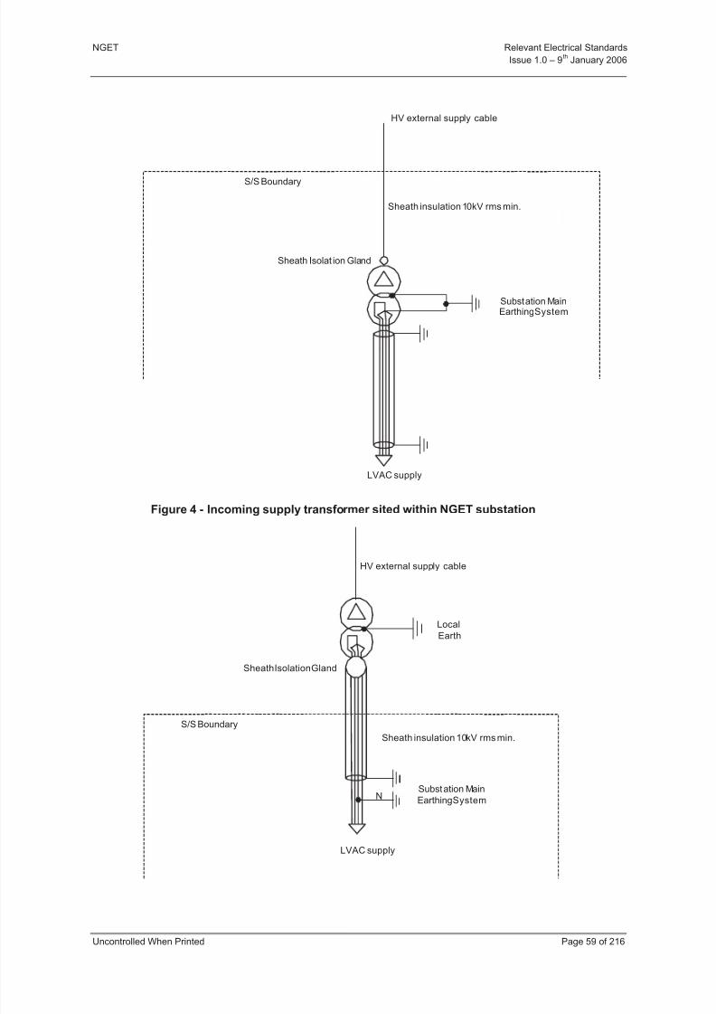
8/3/2019 1 Relevant Standards for Substation Plants
http://slidepdf.com/reader/full/1-relevant-standards-for-substation-plants 66/223
NGET Relevant Electrical Standards
Issue 1.0 – 9th
January 2006
Uncontrolled When Printed Page 59 of 216
HV external supply cable
Sheath Isolat ion Gland
S/S Boundary
Substation MainEarthingSystem
Sheath insulation 10kV rms min.
LVAC supply
Figure 4 - Incoming supply transformer sited within NGET substation
N
Sheath Isolation Gland
HV external supply cable
Sheath insulation 10kV rms min.
S/S Boundary
LVAC supply
Local
Earth
Substation Main
EarthingSystem

8/3/2019 1 Relevant Standards for Substation Plants
http://slidepdf.com/reader/full/1-relevant-standards-for-substation-plants 67/223
NGET Relevant Electrical Standards
Issue 1.0 – 9th
January 2006
Uncontrolled When Printed Page 60 of 216
Figure 5 - Incoming supply transformer sited outside NGET substation
Sheath Isolation Gland
Sheath insulation 10kV rms min.
S/S Boundary
LVAC supply
Substation MainEarthing Sy stem
Figure 6 - Outgoing supply transformer sited within NGET substation
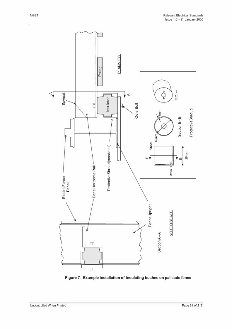
8/3/2019 1 Relevant Standards for Substation Plants
http://slidepdf.com/reader/full/1-relevant-standards-for-substation-plants 68/223
NGET Relevant Electrical Standards
Issue 1.0 – 9th
January 2006
Uncontrolled When Printed Page 61 of 216
P a n e l H o r i z o n t a l R a i l
S a w c u t
P a l i n g
E l e c t r i c F e n c e
P a n e l
F
e n c e U p r i g h t
O u t e r B o l t
P L A N V I E W
N O T T O S C A L E
A
S e c t i o n A - A
A
I n s u l a t o r
B B
S e c t i o n B - B
P r o t e c t i v e S h r
o u d ( s e e d e t a i l )
P r o t e c t i v e S h r o u d
6 2 m m
2 5 m m
S t e e l
1 0 . 2 m m
3 m
m
3 m m
Figure 7 - Example installation of insulating bushes on palisade fence
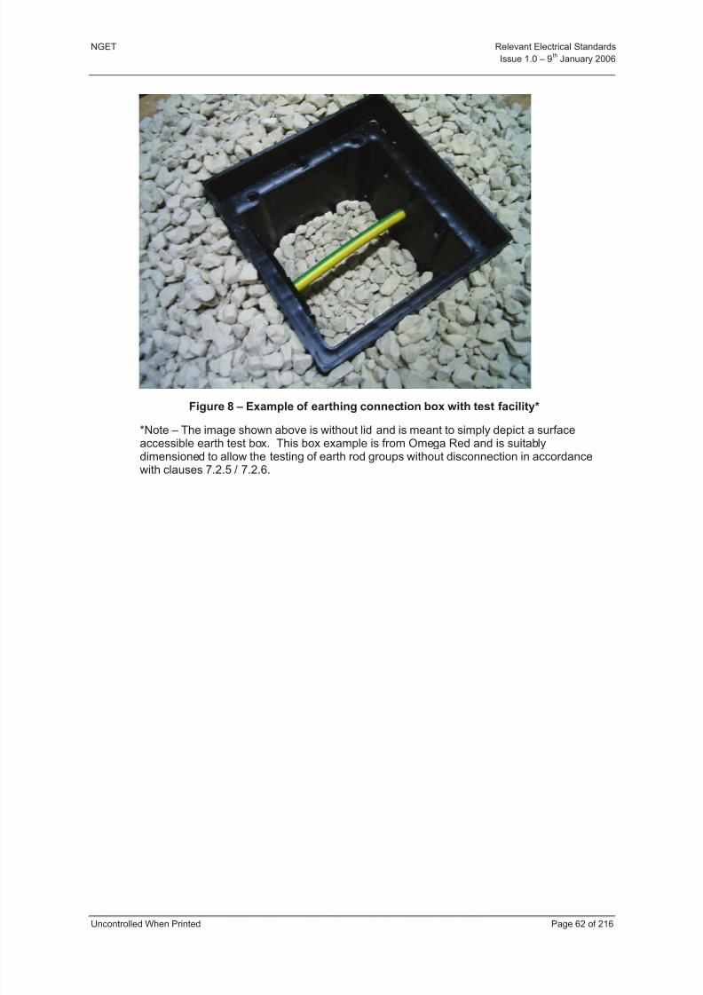
8/3/2019 1 Relevant Standards for Substation Plants
http://slidepdf.com/reader/full/1-relevant-standards-for-substation-plants 69/223
NGET Relevant Electrical Standards
Issue 1.0 – 9th
January 2006
Uncontrolled When Printed Page 62 of 216
Figure 8 – Example of earthing connection box with test facility*
*Note – The image shown above is without lid and is meant to simply depict a surfaceaccessible earth test box. This box example is from Omega Red and is suitablydimensioned to allow the testing of earth rod groups without disconnection in accordancewith clauses 7.2.5 / 7.2.6.
8/3/2019 1 Relevant Standards for Substation Plants
http://slidepdf.com/reader/full/1-relevant-standards-for-substation-plants 70/223
NGET Relevant Electrical Standards
Issue 1.0 – 9th
January 2006
Uncontrolled When Printed Page 63 of 216
8 SECTION 5 - SUBSTATION AUXILIARY SUPPLIES
8.1 PURPOSE AND SCOPE
This Section defines NGET’s technical requirements for the application of substation
auxiliary equipment. This section describes the functional and performance requirements for both ac and dc auxiliary power supplies for equipment in NGET substations.
8.2 GENERAL REQUIREMENTS
Informative: The operational security of NGET substations and the availability of the highvoltage plant and secondary equipment within the substation is dependent upon reliable and secure auxiliary supplies.
8.2.1 Manufacture
Manufacturing facilities shall be certified by a recognised accreditation organisation to BS ENISO 900 1.
Manufacturers shall preferably have in place or be working towards installation of management systems compatible with the international environmental management systemstandard ISO 14001.
8.2.2 Equipment
In order to provide as safe an environment as is reasonably practicable in NGET substationsthe User shall, where appropriate, liase with NGET and equipment suppliers to ensurecurrent ‘best practice’ safety standards and / or methodologies are incorporated intoequipment design, layout and installation. Consideration should be given, in particular, to‘general’ safety issues such as, but not limited to, tripping hazards, sharp edges, equipmentidentification and ease of access for the performance of routine maintenance, repair or replacement.
No-break supplies for protection, control, measurements, telecommunications and other electronic equipment shall normally be fed from 48 V (dc) and/or 110 V (dc) supplies.
Informative: The preferred choice of supply for light current equipment is 110 V (dc)
Alternating current supplies may be used where a short duration supply interruption istolerable (typically 0-2 mins arising from the time taken for a supply to change over or for adiesel standby generator to run up to speed). Where a break is not acceptable and theequipment requires a no-break ac supply such as for a computer and monitor then it shall befed from a dc supplied inverter or a stand-alone uninterruptible power supply (UPS).
Informative: The use of an UPS to power single items of equipment is not desirable and the
preferred option is to provide PC’s and monitors powered directly from a dc supply.
For safety reasons, the use of 230 V (ac) supplies for control systems should be avoidedwhere reasonably practicable. If ac supplies must be used for general control purposes, asuitable transformer providing 110 V with centre tapped earth is recommended to derive anacceptable control voltage.
8.2.3 Alternating Current Supplies
The LVAC power supply shall be designed to provide a voltage maintained within the limits
of 400/230 V + 10%, - 6% and 50 Hz 1%.
All components of the LVAC supply should be capable of operating correctly at the levels of harmonics specified in BS EN 50160.
8.2.4 Direct Current Supplies

8/3/2019 1 Relevant Standards for Substation Plants
http://slidepdf.com/reader/full/1-relevant-standards-for-substation-plants 71/223
NGET Relevant Electrical Standards
Issue 1.0 – 9th
January 2006
Uncontrolled When Printed Page 64 of 216
Both the 48 V and 110 V (dc) supply systems at 400 kV and 275 kV substations shall beprovided by two independent dc supply systems.
Interconnection facilities between the independent dc supply systems for each voltage levelshall be provided at each substation. Common mode faults shall be minimised wherever possible.
Cross connections of dc supply systems between adjacent dispersed relay rooms, where therelay rooms belong to primary 400/275 kV circuits carried on the same route, shall bearranged to avoid common mode faults.
Each independent system shall be designated for a 6 hour standby period with the maximumload of the associated distribution board.
8.3 PERFORMANCE REQUIREMENTS
8.3.1 Alternating Current Supplies
All equipment supplied shall be provided with the following degrees of protection against
ingress of objects and moisture, as specified in BS EN 60529.
Outdoor Equipment: The level of protection during normal operation shall be IP54. Withaccess doors open, without the use of tools, the level of protection of live electricalconductors shall be IP20.
Indoor Equipment: The level of protection during normal operation shall be IP31. Withaccess doors open, without the use of tools, for the level of protection of live electricalconductors shall be IP20.
8.3.2 Direct Current Supplies
Direct current systems shall provide no-break supplies at all times up to the end of thespecified standby period.
The power supply systems and cabling shall be sized to ensure that the battery is capable of supplying the load requirements at the end of the 6-hour standby period.
At the end of the 6-hour standby period the voltage measured at the distribution board , withan ambient temperature of 5ºC, shall not be less than 46 V in the case of 48 V nominalsystems, 102 V in the case of centralised 110 V systems and 93 V for dispersed 110 Vsystems.
The 110 V battery shall be capable of supplying the maximum tripping load at the end of the6 hour standby period. This is defined as the tripping of all the required plant associated withthat battery for a primary busbar fault.
The battery/charger system shall at all timesmaintain the voltage at the distributionboard(s) within the following levels (takinginto account the permissible statutoryvariance in alternating current supply voltageat the charger):
Normal Max. Min.1
Min.2
Voltage Envelope for 110 V nominal system3
125 137.5 102 93
Voltage Envelope for 48 V nominal system 54 60 46 --
8/3/2019 1 Relevant Standards for Substation Plants
http://slidepdf.com/reader/full/1-relevant-standards-for-substation-plants 72/223
NGET Relevant Electrical Standards
Issue 1.0 – 9th
January 2006
Uncontrolled When Printed Page 65 of 216
1 For centralised distribution boards
2 For distribution boards in dispersed relay rooms
3 For smaller capacity batteries where 6 V or 12 V monoblocs are provided eg 100 Ah
or less normal and nominal voltages are 122.6 V and 108 V respectively.
8.4 REFERENCES
This section makes reference or should be read in conjunction with the following documents:
BS EN 50160 Voltage Characteristics of Electricity Supplied by Public DistributionSystems

8/3/2019 1 Relevant Standards for Substation Plants
http://slidepdf.com/reader/full/1-relevant-standards-for-substation-plants 73/223
NGET Relevant Electrical Standards
Issue 1.0 – 9th
January 2006
Uncontrolled When Printed Page 66 of 216
9 SECTION 6 - ANCILLARY LIGHT CURRENT EQUIPMENT
9.1 PURPOSE AND SCOPE
This Section describes the overall functional and performance requirements for ancillary light
current equipment to be used with light current systems provided for protection, control,monitoring and metering. It covers the requirements for:
a) Light current equipment, auxiliary switches and indicators,
b) Cubicles, boxes, and kiosks,
c) Marshalling,
d) Earthing,
e) Marking and labelling,
f) Components and accessories,
g) Interposing relays,
h) Testing Facilities.
9.2 GENERAL REQUIREMENTS
Ancillary light current equipment in substations shall conform to the relevant International or British Standards for its application and be fit for purpose.
The constructional requirements and tests for controlgear assemblies shall comply with BS
EN 60439-1.
Electrical installations shall comply with the appropriate requirements of BS 7671.
The use of auxiliary energising voltages above 110 V (ac) shall be avoided, the preferredvoltage for suchac circuits is 110 V, the use of centre tap earthed 110 V is preferred.Supplies for test purposes above 110 V (ac) shall be labelled as such. Heating and lightingcircuits in cubicles and kiosks shall comply with the requirements of BS 7671. Electricalhazard labels shall be fitted to all plug and sockets connected to systems with nominalvoltages above 125 V (ac) or(dc) warning labels shall be in accordance with BS 5378.
All equipment shall be marked to identify the Manufacturer and the Manufacturer’s reference.
Equipment with elements that can be withdrawn shall have marking on both the fixed andremovable portions, to assist the correct replacement of equipment.
Covers shall be easily removed and replaced without risk of damage to, or inadvertentoperation of, equipment. They shall be constructed and fastened so that they cannot bereplaced incorrectly, or damaged or distorted by their fastenings.
All materials shall be non-ignitable or resistant to flame propagation (tested in accordancewith BS EN 60695).
All materials shall be dimensionally stable i.e. shall be distortion-free to the extent necessaryfor the correct functioning of the equipment in service.
Protective finishes shall be of such a standard that they shall not require renewal during thelife of the equipment in the specified ambient conditions.
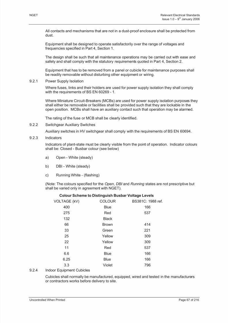
8/3/2019 1 Relevant Standards for Substation Plants
http://slidepdf.com/reader/full/1-relevant-standards-for-substation-plants 74/223
NGET Relevant Electrical Standards
Issue 1.0 – 9th
January 2006
Uncontrolled When Printed Page 67 of 216
All contacts and mechanisms that are not in a dust-proof enclosure shall be protected fromdust.
Equipment shall be designed to operate satisfactorily over the range of voltages andfrequencies specified in Part 4, Section 1.
The design shall be such that all maintenance operations may be carried out with ease andsafety and shall comply with the statutory requirements quoted in Part 4, Section 2.
Equipment that has to be removed from a panel or cubicle for maintenance purposes shallbe readily removable without disturbing other equipment or wiring.
9.2.1 Power Supply Isolation
Where fuses, links and their holders are used for power supply isolation they shall complywith the requirements of BS EN 60269 - 1.
Where Miniature Circuit-Breakers (MCBs) are used for power supply isolation purposes theyshall either be removable or facilities shall be provided such that they are lockable in the
open position. MCBs shall have an auxiliary contact such that operation may be alarmed.
The rating of the fuse or MCB shall be clearly identified.
9.2.2 Switchgear Auxiliary Switches
Auxiliary switches in HV switchgear shall comply with the requirements of BS EN 60694.
9.2.3 Indicators
Indicators of plant-state must be clearly visible from the point of operation. Indicator coloursshall be: Closed - Busbar colour (see below)
a) Open - White (steady)
b) DBI - White (steady)
c) Running White - (flashing)
(Note: The colours specified for the Open, DBI and Running states are not prescriptive butshall be varied only in agreement with NGET).
Colour Scheme to Distinguish Busbar Voltage Levels
VOLTAGE (kV) COLOUR BS381C: 1988 ref.
400 Blue 166
275 Red 537
132 Black
66 Brown 414
33 Green 221
25 Yellow 309
22 Yellow 309
11 Red 537
6.6 Blue 166
6.25 Blue 166
3.3 Violet 796
9.2.4 Indoor Equipment Cubicles
Cubicles shall normally be manufactured, equipped, wired and tested in the manufacturersor contractors works before delivery to site.

8/3/2019 1 Relevant Standards for Substation Plants
http://slidepdf.com/reader/full/1-relevant-standards-for-substation-plants 75/223
NGET Relevant Electrical Standards
Issue 1.0 – 9th
January 2006
Uncontrolled When Printed Page 68 of 216
Cubicles shall comply with the dimensions stated in IEC 60297 Part 2. The cubicle shall berigid, free standing and capable of being fixed down. All equipment cubicles, shall have 19"rack mounting arrangements.
On cubicles where equipment is mounted on a swing door, stops to limit the travel of theequipment frame shall be provided. When closed, the equipment door shall be securedagainst vibration.
The cubicle, by its construction, shall minimise the spread of fire from any cubicle to itsneighbour.
Cubicles shall meet rating IP 44 as a minimum requirement as specified in BS EN 60529.Where individual equipment e.g. relays, have an IP rating less than that specified in theappropriate NGET Technical Requirements, consideration shall be given to increasing thecubicle IP rating to meet the requirement of NGET’s Technical Requirement.
Facilities shall be provided to maintain the air temperature and humidity within the levelsdetailed in Part 4, Section 1, without condensation. Equipment shall be suitable for
operation in its intended environment including the ability to maintain critical functions in theevent of the failure of environments control facilities such as air conditioning.
All cubicles shall be provided with locking facilities.
Equipment on panel fronts shall be flush mounted.
All equipment requiring access for test or adjustment shall be not more than 2.0 m abovepermanent access ways.
9.2.5 Outdoor Kiosks
Outdoor kiosks shall be of rigid construction and suitable for the life of the associated plantwithout any maintenance. Kiosks shall meet Environmental Class 4 conditions, (see Part 4,
Section 1), without any condensation forming and shall meet IP 54 as specified inBS EN 60529.
All equipment, terminals and wiring shall be readily accessible. Doors shall be weatherproof.
An unrestricted view of the instruments without opening the doors shall be provided.Instruments which are required to be read accurately shall not be more than 1.7 m aboveaccess ways, and where vibration is to be expected the instruments shall be on resilientmountings.
The cable entry (eg gland plates) shall be at least 450 mm above ground level and shall bevermin proof and shall project above the inside of the kiosk base to prevent water enteringthe cable.
Kiosks shall be provided with locking facilities.
9.2.6 Termination Boxes
Termination boxes shall be of rigid construction and suitable for the life of the associatedplant without any maintenance. Termination boxes shall not collect condensation.
All terminations and connections shall be readily accessible.
Cable entries (eg glands) shall project above the inside of the termination box base toprevent water entering the cable.
For outdoor termination boxes, cable entries shall always be from below.
When vibration is expected, termination boxes shall be fitted on anti-vibration mountings.
8/3/2019 1 Relevant Standards for Substation Plants
http://slidepdf.com/reader/full/1-relevant-standards-for-substation-plants 76/223
NGET Relevant Electrical Standards
Issue 1.0 – 9th
January 2006
Uncontrolled When Printed Page 69 of 216
Termination boxes for Ambient Class 1, 2 and 3 as detailed in Part 4, Section 1 may beprovided with sliding covers. Other types of covers shall be secured with captive fasteners.Alternatively, doors secured as for cubicles may be provided.
Termination boxes for use outdoors shall be suitable for Ambient Class 4 conditions asdetailed in Part 4, Section 1, mounted so as to prevent pockets or spaces which can collectwater shall meet the requirements of BS EN 60529 with classification IP 54. Indoor termination boxes shall be to IP 44 as specified in BS EN 60529.
Padlocks and locking facilities are required on mechanism and terminal boxes of HV plant for locking-off purposes.
9.2.7 Marshalling
Marshalling cubicles or racks in relay or equipment rooms shall be arranged with externalcables entering the cubicle at the bottom and inter-panel connections entering from the top.External cables shall be glanded above the floor of the cubicle or rack and cores shall beterminated on terminal blocks in number order. Inter-panel connections shall be terminatedon terminal blocks in number order. All cores on both external cables and inter-panelconnections shall be terminated. A jumper field, which shall be installed in the factorywhenever possible, shall be used to interconnect the external cables and the inter-panelconnections.
9.2.8 Earthing
Cubicles, racks, kiosks, and termination boxes shall be connected to the station earthsystem by a 25 mm wide by 3 mm thick copper or aluminium bar, or equivalent. Where acopper earth bar is employed, the stud connection to the earth bar shall be phosphor bronzeor high tensile brass. Where an aluminium earth bar is employed, the stud shall be of galvanised steel.
A radial type earthing system with a single connection point to the substation earth mat shallprovide earthing of equipment within a cubicle. As a minimum a cubicle shall be fitted with
an earth terminal or stud as specified below, for kiosks and termination boxes.
Kiosks and termination boxes shall be provided with a 10 mm diameter, low resistivity earthterminal or stud. This termination shall be in an accessible position, clear of obstruction.
Electrical continuity shall be maintained between cubicles and associated termination boxes.If electrical continuity is not inherently provided between the cubicles and associated
termination box then a copper earth wire of cross-section not less than 2.5 mm shallinterconnect the equipments. Doors, covers, subracks etc shall be similarly interconnectedto ensure electrical continuity to earth.
The disconnection of any one piece of equipment from earth shall not disconnect any other equipment.
Where earth connections are made to metal work, paint shall be removed to ensure a goodelectrical contact, and the connection protected against corrosion.
All current transformer (CT) secondary circuits shall be connected to earth at one point of thecircuit only. This connection shall be a secure link and shall be labelled as an earth link.The link shall be of a captive type. All circuit earth connections and links shall be readilyaccessible in the relay cubicle or associated terminal box.
The secondary circuits of interposing transformers shall not normally be earthed.
A notice warning of dangerous voltage shall be provided adjacent to the CT secondary circuitlink.
9.2.9 Marking and Labelling of Equipment

8/3/2019 1 Relevant Standards for Substation Plants
http://slidepdf.com/reader/full/1-relevant-standards-for-substation-plants 77/223
NGET Relevant Electrical Standards
Issue 1.0 – 9th
January 2006
Uncontrolled When Printed Page 70 of 216
Labels shall be provided for identifying all equipment requiring operation and maintenance.
Additional warning labels shall be supplied where specified.
All labels and inscriptions shall be resistant to wear or deterioration in the ambient conditionsprevailing and shall be suitable for the life of the equipment.
Adhesives for instruction labels and identification labels within enclosures shall be tested inaccordance with BS EN 28510-2.
All terminals of equipment shall be marked. Wire end terminations shall be identifiable bythe use of 'dependent local-end marking' in accordance with IEC 391 Sections 3.4.a.1 and5.1.2 except for telecommunications equipment where marking may be omitted where thedesign and arrangement of the equipment is such that marking is unnecessary (e.g. colour coding and wire schedules etc).
Marking and labelling of equipment shall provide a logical and convenient means by whichthe lifetime management of the equipment can take place.
Where identification labels are affixed to doors or covers, a similar label shall be providedand sited so that it is visible when the door or cover is opened or removed.
Labels shall be consistently sited and not obscured by any other equipment. There must beno ambiguity as to the equipment to which the labelled parts refer.
Circuit labels shall be provided on the front of cubicles and on the back for rear accesscubicles.
Each rail/group of terminals shall be identified with an appropriate rail/group reference.Terminals within each rail/group shall be individually sequentially numbered. The labelsshall be mounted such that they are not disassociated from the mouldings when access to
terminals is required. 9.2.10 Terminal Blocks
Terminal blocks shall be adequately rated for their duty and conform to the appropriaterequirements of BS EN 60947-7-1.
Terminal block labels shall be of insulation material.
All terminal blocks shall be demonstrated to provide reliable and secure wiring terminationsand shall be suitable for the life of the primary equipment without maintenance.
Terminal blocks in outdoor kiosks or equipment cubicles shall have separate terminals for incoming and outgoing connections, not more than two terminations being permitted on any
one terminal excluding any purpose made interconnectors.
Wire ends shall be marked as specified in Section 9.2.9.
All terminal blocks shall by virtue of their design prevent accidental short-circuiting betweenadjacent terminals.
Terminal covers shall be provided where terminal blocks are used at nominal voltages above125 V (ac) or (dc). , or where high transient over-voltages may occur, eg currenttransformer circuits. They shall be to IP20 as specified in BS EN 60529. They shallpreferably clip onto the mouldings, with warning labels as necessary where hazardousvoltages could be present.
No live metal shall be exposed at the back of terminal blocks.
8/3/2019 1 Relevant Standards for Substation Plants
http://slidepdf.com/reader/full/1-relevant-standards-for-substation-plants 78/223
NGET Relevant Electrical Standards
Issue 1.0 – 9th
January 2006
Uncontrolled When Printed Page 71 of 216
For screw type terminal blocks associated with CT wiring in panels, the design shall be suchthat loosening off of the primary captive arrangement e.g. the terminal screw shall not leadto a change in the current carrying capability. Alternatively, the terminal block manufacturer shall demonstrate that by virtue of the design of the terminal block, loosening off of theprimary captive arrangement through vibration or other environmental factors, cannot occur.
Test sockets, where provided, preferably shall be suitable for test plugs of 4 mm diameter,but a smaller size may be acceptable where the terminal block dimensions make 4 mmimpractical.
9.2.11 Terminations
The application and conditions of use for conductor terminations shall be in accordance withthe terminal manufacturers requirements. The design of conductor termination or the meansby which a conductor is terminated shall be appropriate to the application, taking intoaccount the lifetime management of the equipment.
Where insulation displacement type terminations are used conductors shall have sufficientexcess length to permit a minimum of four re-connections during the life of the equipment.
a) Crimps
Crimps shall meet the requirements of BS 4579 Part 1.
Barrel sizes shall suit the sizes and forms of conductor supplied. Barrels that take arange of conductor sizes are acceptable.
Where conductor insulation support is required (flexible stranded conductor below 0.5mm
2and single strand conductor of 1 mm
2and below), this shall be provided by an
extended sleeve over the barrel.
Each crimped termination shall be fitted with one conductor only.
Crimping shall be carried out in accordance with the crimp manufacturers instructions.
b) Heavy Duty Plug and Socket connectors
Plug and socket connectors shall be equipped with a coding facility to avoid incorrectconnections being made. The design of connector used shall ensure correctalignment of the pins on connection.
Each plug and socket shall be identified. Where the connector contains currenttransformer circuits the plug body shall be coloured yellow unless specific designfeatures are provided to prevent inadvertent open circuiting of the current transformer circuit, in the event of the connector being split. The socket body shall carry a warning
label "CAUTION CURRENT TRANSFORMER CIRCUITS".
The degree of protection provided on plug and socket connectors for use in protectionand control cubicles sited in relays rooms shall be to IP 50 as specified in BS EN60529. Outdoor types shall be a minimum of IP 54 and shall be suitable for theenvironment in which they are applied over the life of the associated primaryequipment.
Cable strain relief shall be provided at the cable gland, such that the integrity of theplug/socket housing IP rating is not affected.
Male and female electrical contacts for use in protection and control systems shall notbe of the stamped metal design.
9.2.12 Small Wiring
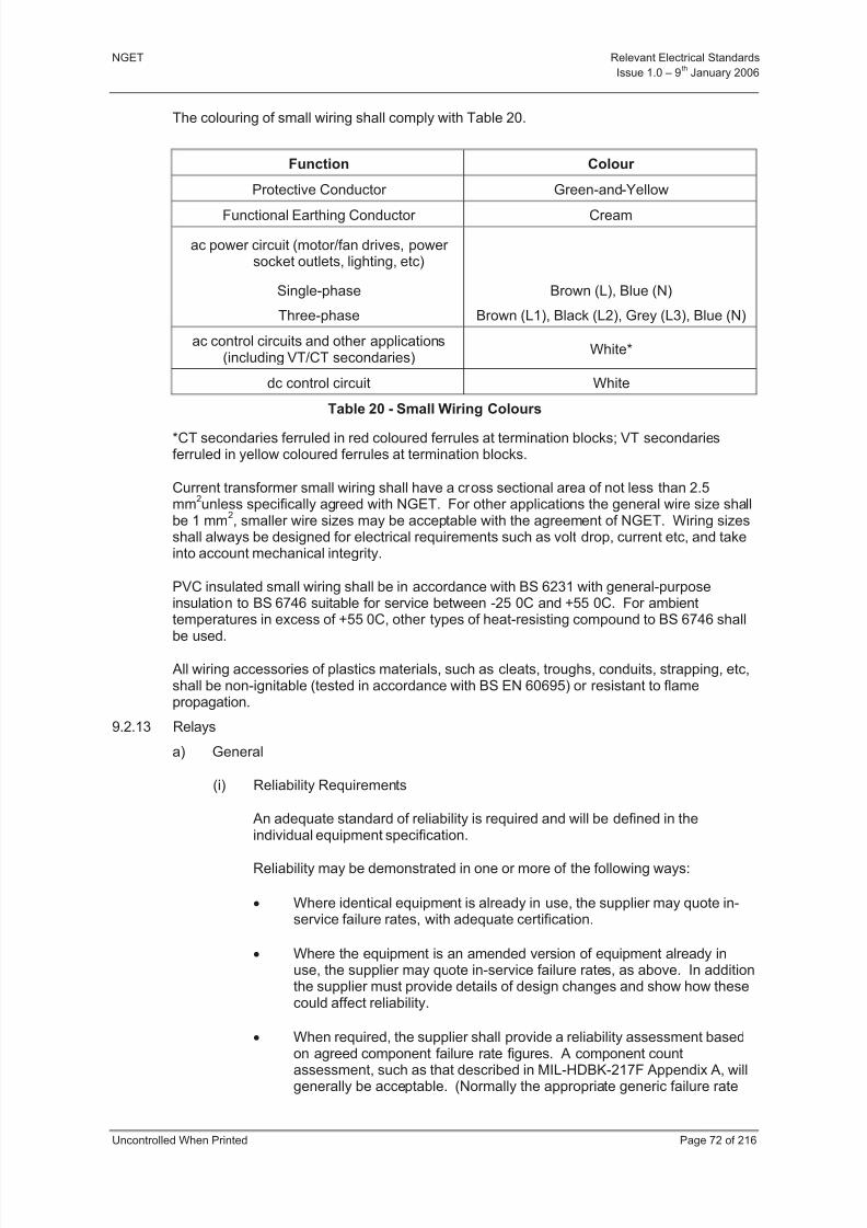
8/3/2019 1 Relevant Standards for Substation Plants
http://slidepdf.com/reader/full/1-relevant-standards-for-substation-plants 79/223
NGET Relevant Electrical Standards
Issue 1.0 – 9th
January 2006
Uncontrolled When Printed Page 72 of 216
The colouring of small wiring shall comply with Table 20.
Function Colour
Protective Conductor Green-and-Yellow
Functional Earthing Conductor Cream
ac power circuit (motor/fan drives, power socket outlets, lighting, etc)
Single-phase
Three-phase
Brown (L), Blue (N)
Brown (L1), Black (L2), Grey (L3), Blue (N)
ac control circuits and other applications(including VT/CT secondaries)
White*
dc control circuit White
Table 20 - Small Wiring Colours
*CT secondaries ferruled in red coloured ferrules at termination blocks; VT secondariesferruled in yellow coloured ferrules at termination blocks.
Current transformer small wiring shall have a cross sectional area of not less than 2.5mm
2unless specifically agreed with NGET. For other applications the general wire size shall
be 1 mm2, smaller wire sizes may be acceptable with the agreement of NGET. Wiring sizes
shall always be designed for electrical requirements such as volt drop, current etc, and takeinto account mechanical integrity.
PVC insulated small wiring shall be in accordance with BS 6231 with general-purposeinsulation to BS 6746 suitable for service between -25 0C and +55 0C. For ambienttemperatures in excess of +55 0C, other types of heat-resisting compound to BS 6746 shall
be used.
All wiring accessories of plastics materials, such as cleats, troughs, conduits, strapping, etc,shall be non-ignitable (tested in accordance with BS EN 60695) or resistant to flamepropagation.
9.2.13 Relays
a) General
(i) Reliability Requirements
An adequate standard of reliability is required and will be defined in theindividual equipment specification.
Reliability may be demonstrated in one or more of the following ways:
Where identical equipment is already in use, the supplier may quote in-service failure rates, with adequate certification.
Where the equipment is an amended version of equipment already inuse, the supplier may quote in-service failure rates, as above. In additionthe supplier must provide details of design changes and show how thesecould affect reliability.
When required, the supplier shall provide a reliability assessment based
on agreed component failure rate figures. A component countassessment, such as that described in MIL-HDBK-217F Appendix A, willgenerally be acceptable. (Normally the appropriate generic failure rate

8/3/2019 1 Relevant Standards for Substation Plants
http://slidepdf.com/reader/full/1-relevant-standards-for-substation-plants 80/223
NGET Relevant Electrical Standards
Issue 1.0 – 9th
January 2006
Uncontrolled When Printed Page 73 of 216
figures for the Ground Fixed environment should be used). Other methods may be supplied in the individual equipment specification.
(ii) Environmental Requirements
The equipment shall be subjected to environmental factors such as electricalinterference, supply voltage variations, nuclear radiation, dust, vibration,temperature, and salt mist. Where special equipment enclosures are requiredto satisfy these requirements, the supplier shall define its Degree of Protectionby stating its IP Code as given in BS EN 60529 (IEC 60529).
The following clauses define the conditions which the equipment needs towithstand without either the performance being degraded or the life beingshortened.
Temperature and Humidity
o Equipment shall operate within its functional specification over therange of the specified atmospheric environmental classes, asdetailed in Part 4, Section 1.
o Where any item of equipment is to be mounted within an enclosurehousing other items of equipment, it shall be capable of normal
operation at a temperature 15C higher than the upper temperaturelimit of the environmental class.
o The temperature rise above ambient within an enclosure, when the
equipment is operating normally, shall not exceed 10 C.
(iii) Mechanical
o Shock and Vibration
o The Drop and Topple Test (Part 4, Section 16) shall not affectperformance life.
o Where specified, equipment shall conform to the requirements of Part 4, Section 16, Vibration Test.
o Where responsible for installation, the contractor shall ensure thatharmful levels of vibration do not reach the equipment throughmountings and external connections.
o Protection equipment shall conform to the requirements of Part 4,Section 16, shock, bump and seismic tests.

8/3/2019 1 Relevant Standards for Substation Plants
http://slidepdf.com/reader/full/1-relevant-standards-for-substation-plants 81/223
NGET Relevant Electrical Standards
Issue 1.0 – 9th
January 2006
Uncontrolled When Printed Page 74 of 216
Self-generated Vibration
Equipment shall not generate vibration at a level which could be damagingto its performance or that of other equipment or personnel.
(iv) Electrical
The equipment shall meet its specified functional performance under the supplyand electrical environmental parameters detailed below.
(v) Supply Parameters
Equipment may operate from a variety of supplies. The supply parameters aredefined in Part 4, Section 5.
(vi) Interference Immunity
The interference suffered by a ‘victim’ equipment is dependent not only on the
interference levels to which the equipment itself is directly subject but also thelevels existing in the areas through which the cables connected to it pass. Thisconcept is defined in BS EN 50082-1 Section 4 and Figure 1 is based on thisdefinition.
When a plug-in relay is utilised it shall have a device to retain the relay or element in place. It shall not be possible to insert a plug-in relay into its baseincorrectly.
The relay shall have an enclosure specification to IP 50 as specified in BSEN60529 and have transparent covers.
It shall not be possible to replace a cover incorrectly.
The contact performance for relays used for local control purposes shall be inaccordance with the requirements stated in the Table 21 below, where relevant.However a lower rating may be used where it can be shown that the contactsare suitable for the particular application.
Make and Carry Capacity
200 ms 1 s continuous
dc (L/R >10 ms) 3000 W (with amaxima of 20 A
and 300 V)
2000 W (with amaxima of 10 A
and 300 V)
1000 W (with amaxima of 4 A
and 300V)
Continuous Current Carrying Capacity (contacts already closed)
200 ms 1 s continuousdc minimumcurrent 35 A 20 A 4 A
Breaking Capacity
dc inductive(L/R > 40 ms)
30 W (with a maxima of 2 A and 300 V)
dc resistive 60 W
Table 21 – Contact Performance Requirements
8/3/2019 1 Relevant Standards for Substation Plants
http://slidepdf.com/reader/full/1-relevant-standards-for-substation-plants 82/223
NGET Relevant Electrical Standards
Issue 1.0 – 9th
January 2006
Uncontrolled When Printed Page 75 of 216
Interposing relays shall comply with the requirements of IEC 60255-7.
The relay will be required to operate either from a 48 V nominal dc supply as or from a 110 V (dc) supply with voltage envelopes as specified in Part 4, Section5.
(vii) In/Out Switching Relays for Protection and Auto-Reclose Equipments
The relay shall be of the latched type with an operate and reset coil. Theoperate coil shall perform the 'Out' function. A contact in series with each coilshall break the coil current during, or at the end of the mechanical travel. Ninefurther contacts shall be provided. A self resetting indicator on the relay thatdisplays the words 'IN' and/or 'OUT' when applicable and masks theinapplicable word shall be provided.
A hand resetting mechanism shall not be fitted.
b) Control Interposing Relays
The contacts of interposing relays for control purposes shall be suitable for controllinginductive circuits associated with the operating gear of the equipment to be controlled.
48 V (dc) control interposing relays shall be double pole switched.
110 V control interposing relays shall be Class 2 in Table 22 or shall be double-poleswitched.
9.2.14 Testing Facilities
Facilities shall be provided to enable all routine maintenance testing to carried out from thefront of the equipment.
9.3 PERFORMANCE REQUIREMENTS
9.3.1 Enclosures and Equipment
Enclosures, equipment and ancillary components etc, shall be designed to operate under theappropriate general ambient conditions specified in Part 4, Section 1 – Table 1.
9.3.2 Terminal Blocks
Terminal blocks for use on CT circuits shall have a rated insulation voltage of 1 kV and betested with a test voltage selected from BS EN 60947-7-1 Table V (3500 V rms). Theterminal block shall also meet the requirements of the impulse voltage test in IEC 60255-5with a test voltage of 5 kV.
Terminal blocks for use in 110 V and 48 V (dc) systems shall have a rated insulation voltageup to 300 V and be tested with a test voltage selected from BS EN 60947-7-1 Table V.
9.3.3 Plug and Socket Type Connectors
The rated insulation and impulse voltage shall be accordance with the requirements for terminal blocks.

8/3/2019 1 Relevant Standards for Substation Plants
http://slidepdf.com/reader/full/1-relevant-standards-for-substation-plants 83/223
NGET Relevant Electrical Standards
Issue 1.0 – 9th
January 2006
Uncontrolled When Printed Page 76 of 216
9.3.4 Control Interposing Relays
Relays associated with the direct operation of switchgear shall have Class 1 or Class 2performance as specified in Table 22.
Class 1 2
dc System Nominal Voltage (V) 110 48 110
Relay rated voltage (V) 125 48 125
Normal Working Voltage (V) 125 54 125
Operative Voltage Range (V)87.5 to137.5
37.5 to 6087.5 to137.5
Energising current at or below whichthe relay shall not operate (mA)
25 10 50
Capacitance discharge test * N/A N/A10 µF at150 V
Thermal withstand voltage at 40oC
ambient (V) 137.5 60 137.5
Table 22 - Control Interposing Relays
9.3.5 48 V dc Control Interposing Relays
The relay shall function correctly with 200 in series with each coil and with a batteryvoltage of 46 V.
9.3.6 110 V dc Control Interposing Relays
Interposing relays energised at 110 V (dc) shall operate within their declared specificationwith 100 in series with the operate coil.
9.4 TEST REQUIREMENTS
Equipment offered to meet this specification shall have passed the test requirements laiddown in applicable International or British Standards.
9.5 TECHNICAL DATA
The equipment supplier shall provide technical data to support the general, performance andtest requirements where required by NGET to demonstrate compliance with thisspecification.
9.6 REFERENCES
This Section makes reference to, or should be read in conjunction with, the following
documents:-
BS EN 28510-2 Adhesives - Peel Test for a Flexible Bonded to Rigid Test SpecimenAssembly. 180 Peel
BS EN 60269-1 Low Voltage Fuses Part 1: General Requirements
BS EN 60439-1 Low-Voltage Switchgear and Controlgear Assemblies - Part 1Requirements for Type Tested and Partially Type Tested Assemblies
BS EN 60529 Degrees of Protection Provided by Enclosures
BS EN 60694 Common Clauses for High-Voltage Switchgear and Controlgear Standards

8/3/2019 1 Relevant Standards for Substation Plants
http://slidepdf.com/reader/full/1-relevant-standards-for-substation-plants 84/223
NGET Relevant Electrical Standards
Issue 1.0 – 9th
January 2006
Uncontrolled When Printed Page 77 of 216
BS EN 60695 Fire Hazard Testing for Electrotechnical Products
BS EN 60947-7-1 Terminal Blocks for Copper Conductors
IEC 391 Marking of Insulated Conductors
IEC 60255-5 Electrical Relays - Insulation Tests for Electrical Relays
IEC 60255-7 Test and Measurement Procedures for Electromechanical All-or-NothingRelays
IEC 60297 Dimensions of Mechanical Structures of the 482.6 mm Series
BS196 Plugs, Socket-Outlets Cable-Couplers and Appliance-Couplers
BS 4579 Part 1 Compression Joints on Copper Conductors
BS 5378 Safety Signs and Colours
BS 6121 Mechanical Cable Glands
BS 6231 PVC-Insulated Cables for Switchgear and Controlgear Wiring
BS 6746 Specification for PVC Insulation and Sheath of Electric Cables
BS 7671 Requirements for Electrical Installations

8/3/2019 1 Relevant Standards for Substation Plants
http://slidepdf.com/reader/full/1-relevant-standards-for-substation-plants 85/223
NGET Relevant Electrical Standards
Issue 1.0 – 9th
January 2006
Uncontrolled When Printed Page 78 of 216
10 SECTION 7 - SUBSTATION INTERLOCKING SCHEMES
10.1 PURPOSE AND SCOPE
This document defines the technical requirements of interlocking schemes for NGET
equipment and for Users equipment directly connected to The Transmission System inEngland and Wales.
This functional Specification is applicable to interlocking for air (AIS) and gas (GIS) insulatedswitchgear at substations connected to the Transmission System in England and Wales withequipment rated at 145, 300 or 420 kV.
10.2 GENERAL REQUIREMENTS
10.2.1 Common Requirements
So that operators do not compromise the integrity of the Transmission System in Englandand Wales by incorrect or inadvertent operation of equipment.substations shall be providedwith a full interlocking scheme to ensure that all disconnectors, fixed earthing switches (or
other interlocked earthing devices) and where required circuit-breakers, are operated in thecorrect sequence.
In substations where NGET is a joint occupier and/or has operational responsibility for switchgear then the interlocking shall also be designed with consideration of personnelsafety.
10.2.2 Interlocking schemes shall cover the following conditions:-
a) Interlocking between circuit breakers and disconnectors to ensure disconnectors donot make or break load currents.
b) Interlocking between disconnectors and earthing switches to ensure that earthingswitches cannot be closed on to a locally energised circuit and cannot be energised,
when closed, by operation of disconnectors.
c) Interlocking between disconnectors and adjacent earthing switches to permit operationof the disconnector when earthing switches are closed on both sides of thedisconnector. Such interlocking is not required for equipment rated at 145 kV andbelow.
d) To ensure correct sequence of on load busbar transfer switching operations atmultiple busbar substations.
e) To ensure that a bus-coupler or bus-section circuit breaker is only closed with itsassociated disconnectors both open or both closed.
f) For equipment at sites where NGET is the Occupier, to restrict access to areas of thesubstation where safety clearances may be infringed unless appropriate safetymeasures, such as isolation and earthing, have been taken.
The interlocking of switching sequences involving only power operated switchgear shall beby electrical means. The correct interlocking status shall be confirmed automatically oninitiation of an operation from any control position or from auto-switching or sequential-isolation equipment.
The interlocking of switching sequences involving manually operated switchgear may be byelectrical or mechanical means. The interlocking shall be designed such that the correctinterlocking status must be confirmed immediately before an operation.
Interlocking systems shall, where reasonably practicable, be fail-safe. They shall not bedefeated without the use of tools, clip leads etc or a purpose designed override facility.

8/3/2019 1 Relevant Standards for Substation Plants
http://slidepdf.com/reader/full/1-relevant-standards-for-substation-plants 86/223
NGET Relevant Electrical Standards
Issue 1.0 – 9th
January 2006
Uncontrolled When Printed Page 79 of 216
Interlock override facilities shall be lockable with a unique lock or shall be lockable by meansof a safety padlock.
Partial interlocking of earthing switches at circuit-entries to the substation is acceptablewhere it is not reasonably practicable to extend the interlocking to the remote enddisconnectors. Any partially interlocked earthing switch shall be provided with a warninglabel stating 'WARNING, THIS EARTHING SWITCH IS NOT FULLY INTERLOCKED'.
Interlocking shall be effective for switching and operating sequences when they are beingfollowed in either direction (for example; if an earthing switch must be closed before anaccess gate can be opened then the gate must be secured closed before the earthing switchcan be opened).
Interlocking schemes shall, where reasonably practicable, provide the maximum operationalflexibility and shall not unnecessarily impose fixed operating sequences.
Where an interlocking scheme is being supplied for an extension to an existing substation atthe same operating voltage then, unless otherwise agreed by NGET, the interlocking
philosophy shall match that existing.
Interlocking for a substation extension shall be fully interfaced with the existing interlockingscheme to achieve the functional requirements specified in this document.
10.2.3 Mechanical Interlocking
Mechanical interlocking systems shall be designed to provide a level of security andreliability comparable with equipment specified in 10.2.4.
10.2.4 Mechanical interlocking shall be by key operated systems.
Interlock keys shall be of a non-masterable design (ie no master key can be supplied or manufactured). Differs shall not be repeated on the same substation site.
Note: Differ is the term for the difference in a key that prevents it being interchangeable withanother.
Interlock keys shall be engraved with an identifying reference which shall be unique to thatsubstation site. The identifier shall, where appropriate, include the system number of theswitching device where the key is located during normal operation. Key locations shall bemarked with the identifier of the required key.
Where key exchange boxes are provided they shall be located in convenient positions withregard to normal substation operating sequences.
Where mechanical key interlocking is fitted to disconnector and earthing switch mechanismsthe requirements specified in Part 4, Section 10 shall apply.
10.2.5 Electrical Interlocking
A facility shall be provided to allow the interlock system of each disconnector or earthingswitch to be defeated without disturbing wiring. The facility shall meet the requirements of clause 10.2.2.
Note: This may take the form of a self-resetting switch or push-button to bypass electrical circuits.
Disconnector and earthing switch mechanisms which form part of electrical interlockingschemes shall meet the requirements of Part 4, Section 10.
10.3 Performance Requirements
Mechanical and hard-wired electrical interlocking schemes shall operate satisfactorily under the full range of environmental conditions specified for the associated primary equipment.
8/3/2019 1 Relevant Standards for Substation Plants
http://slidepdf.com/reader/full/1-relevant-standards-for-substation-plants 87/223
NGET Relevant Electrical Standards
Issue 1.0 – 9th
January 2006
Uncontrolled When Printed Page 80 of 216
11 SECTION 8 – SYNCRONISING
11.1 SCOPE
This Section details the functional, performance and interface requirements for synchronising
associated with the qualification of circuit breaker closure on the Transmission System inEngland and Wales. It is also applicable to those associated circuit breakers not owned byNGET but where such qualification is necessary in order to ensure the safety of personnel,plant and equipment
It defines the operations to be undertaken by the synchronising equipment in undertakingeither the automatic or manual closure of a circuit breaker or switch with synchronising. ThisSection is applicable to the interfacing to all synchronising facilities for control actionsundertaken from either the Remote or Substation control points.
11.2 DEFINITIONS
Informative: When voltages are present on both sides of an open circuit breaker it is
necessary to ensure that these voltages are reasonably in synchronism before closure of thecircuit breaker. Two possible conditions apply:
a) More usually, the voltage vectors are static in relation to each other with a fixed phaseangle between them and;
b) Rare occasions when the voltage vectors are at different frequencies because thesystem has become split.
In addition to the two synchronising conditions above, one or both of the voltages may beunavailable in which case the circuit breaker must be closed to energise a dead line, dead busbar or to close a circuit breaker in a dead system.
11.2.1 Check SynchronisingCheck Synchronising is the term which has historically been used by NGET to check that thevoltage vectors across an open circuit breaker are within preset limits of magnitude, phaseangle and practically zero slip. This condition is the most common when closing circuitbreakers with voltages on either side.
11.2.2 DAR
Delayed Automatic Reclose as applied by NGET to feeder circuits usually comprising or mainly comprising overhead line whereby, following the operation of a main protection andsubsequent trip of a circuit, the circuit is automatically switched back into service after aminimum period of 10 seconds. The first circuit breaker to close energises the feeder byperforming a Dead Line Charge (DLC). The second circuit breaker to close requires that thevoltages across its open contacts are reasonably in synchronism. DAR is also applied tocertain transformer LV circuit breakers when the transformer is banked on its HV side with afeeder that has DAR.
11.2.3 Incoming Voltage
The incoming voltage is the voltage on the opposite side of an open circuit breaker from therunning voltage. At busbar-type substations the incoming voltage is on the feeder or transformer side of the circuit breaker. In those cases where the distinction betweenincoming and running voltages is not clear, for example bus section circuit breakers, thevoltages may be identified as ‘A’ and ‘B’ voltages where the ‘A’ voltage is normallyassociated with the main busbar or the lowest numbered busbar or mesh corner.

8/3/2019 1 Relevant Standards for Substation Plants
http://slidepdf.com/reader/full/1-relevant-standards-for-substation-plants 88/223
NGET Relevant Electrical Standards
Issue 1.0 – 9th
January 2006
Uncontrolled When Printed Page 81 of 216
11.2.4 Phase Angle
Phase angle is the angular difference in degrees between the incoming voltage vector andthe running voltage vector across the open contacts of a circuit breaker.
11.2.5 Power System Synchronising
Power system synchronising, or simply System Synchronising, is the term which hashistorically been used by NGET to cover the situation in paragraph 11.2 b) above. This iswhen a circuit breaker is being closed to re-parallel a part of the transmission system thathas become separated from the main part of the transmission system i.e. islanded. It isnecessary to check that the voltage vectors across this open circuit breaker are withinacceptable limits of magnitude, phase angle and slip when the two parts of the transmissionsystem are running asynchronously.
11.2.6 Running Voltage
The running voltage is the voltage on the substation side of an open circuit breaker acrosswhich synchronism is to be checked.
11.2.7 Slip
Slip is the frequency difference between the two voltage vectors across the contacts of anopen circuit breaker and is measured in Hertz (Hz).
11.3 GENERAL REQUIREMENTS
The system shall be arranged such that synchronising under manual control can only takeplace on one circuit at a time on each voltage level at any one substation.
11.3.1 Synchronising Scheme and Voltage Selection Facilities
The voltage supplies for synchronising on systems operating at 400 kV, 275 kV and 132 kVshall be derived from a single phase-to-earth (usually yellow phase) primary voltage bymeans of single phase VT.
The synchronising scheme shall be able to cater for substation extensions
Two basic schemes of synchronising are required to cover the substation layouts used byNGET:
a) Busbar Stations - The standard scheme shall be based on the use of either busbar VTs or individual circuit VTs with a suitable voltage selection scheme for selection of the appropriate supplies for synchronising purposes.
Informative: Where busbar VTs are not provided a simple priority scheme is preferred so that circuit VT supplies are not connected in parallel and the busbar running voltage is derived from only one VT from the circuit having the highest priority.
b) Mesh Type Stations - The standard scheme shall be based on a ring system with asuitable voltage selection scheme for selection of the appropriate supplies for synchronising purposes.
The synchronising equipment shall be capable of selecting the appropriate runningvoltage for synchronising by checking the position of disconnectors and circuitbreakers.
8/3/2019 1 Relevant Standards for Substation Plants
http://slidepdf.com/reader/full/1-relevant-standards-for-substation-plants 89/223
NGET Relevant Electrical Standards
Issue 1.0 – 9th
January 2006
Uncontrolled When Printed Page 82 of 216
11.3.2 Voltage Parameters and Burdens
The ac measuring system shall be designed to be earthed and use interposing voltagetransformers (IVT) supplied from the 63.5 V secondary side of voltage transformersconnected to the primary plant.
11.3.3 Interposing Voltage Transformers
The rating shall be designed to suit the requirements of the scheme.
The synchronising facilities shall incorporate suitable means to interface the voltage outputsfrom main VTs, providing adequate isolation and having an adjustable means of ratio error correction.
11.3.4 Synchronising Function
The equipment is required to operate for check synchronising, system synchronising anddead line/dead bar conditions and shall automatically select the appropriate method of closure dependant on settings and from measurement of the incoming and running voltages.
The equipment shall automatically select check or system synchronise, from measurement
of the relative frequency between the incoming and running voltages.
The normal or default mode shall be as a check synchroniser. On initiation, the equipmentshall operate in the check synchronise mode.
Upon receipt of a close control input and subsequent initiation of the synchronising functionan output shall be provided to indicate that synchronising is in progress. The output shallremain active until either the Circuit Breaker has closed or the synchronising sequence hastimed out.
A facility shall be provided to inhibit the operation of the synchronising function for the failureof either incoming or running VT supplies. This may be achieved by the use of either:
a) Appropriate auxiliary switch contacts from each VT MCB
b) A suitable algorithm within the equipment
c) A combination of (a) and (b) above
Circuit breaker closure shall be prevented and operation inhibited for either an under-voltageor differential voltage condition outside the settings chosen within the range stated inTable 24.
Receipt of the close command shall initiate the Synchronising timer. This timer defines themaximum duration for attempting to close the circuit breaker and the sequence shall abort
and reset if the circuit breaker has failed to close at the end of this period.
Upon receipt of the close control and subsequent circuit breaker close indication theSynchronising timer shall be reset and the synchronising sequence cleared down.
Outputs shall be initiated without any appreciable delay and any delay shall be constant andquantified.
If the dc supplies or incoming and running voltages are removed the synchronising closeoutput shall be prohibited except when DLLB, LLDB and DLDB modes have been pre-selected and the conditions have been detected.

8/3/2019 1 Relevant Standards for Substation Plants
http://slidepdf.com/reader/full/1-relevant-standards-for-substation-plants 90/223
NGET Relevant Electrical Standards
Issue 1.0 – 9th
January 2006
Uncontrolled When Printed Page 83 of 216
11.3.5 Energising Check
The energising check facility shall be selectable and shall be configurable for allcombinations of the following:
a) Dead line live bus (DLLB)
b) Dead bus live line (DBLL)
c) Dead bus dead line (DBDL)
The voltage levels, which define both live and dead conditions, shall be configurableseparately and within the ranges shown in Table 24.
11.3.6 Check Synchronising
Pre-set selectable values of phase angle shall be provided in the range shown in Table 24.
Whilst in check synchronising mode the equipment shall prevent closure in the event of slipbeing in excess of a pre selected value in the range defined in Table 24. This shall be
irrespective of the phase angle setting.
If during the period when the function is verifying the system phase angle the voltage vectorsmove out of the phase angle setting and system synchronising conditions are not detected,circuit breaker closure shall be prevented.
11.3.7 System Synchronising
The System Synchronising mode of operation shall commence automatically upon detectionof a close control and detection of slip within pre-set selectable values.
The initiation of the system synchronising function shall result in the following actions:
a) Check Synchronising closure shall be inhibited whilst asynchronous conditions aredetected.
b) The System Synchronising mode of the device is primed to permit closure of thecircuit breaker to proceed within the limits specified for the System Synchronisingfunction.
c) An output is initiated to provide external indications that the mode of closure haschanged. The output shall remain active until either; the Circuit Breaker has closed,asynchronous conditions are no longer detected or the synchronising sequence hastimed out.
When the system synchronising mode is activated the close output shall be initiated with the
minimum delay, provided the following requirements are met:
d) The phase angle between the incoming and running voltages is decreasing andmeasures less than a pre-set selectable value in the range defined in Table 24.
e) The slip frequency is within the pre-selected values defined in Table 24.
f) The under-voltage or differential check facilities have not operated.
The circuit breaker operating time and measured slip should be taken into account whenoperating in System Synchronising mode to ensure that circuit breaker closure occurs withinthe phase angle window of closure.
Informative: The preferred method for System Synchronising closure shall includecompensation for the measured slip and the circuit breaker closing time to ensure that whenthe closing command is issued the breaker closes at zero degrees.
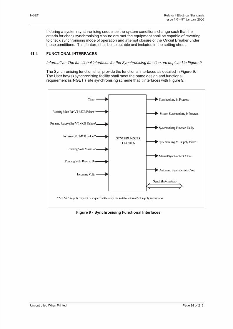
8/3/2019 1 Relevant Standards for Substation Plants
http://slidepdf.com/reader/full/1-relevant-standards-for-substation-plants 91/223
NGET Relevant Electrical Standards
Issue 1.0 – 9th
January 2006
Uncontrolled When Printed Page 84 of 216
If during a system synchronising sequence the system conditions change such that thecriteria for check synchronising closure are met the equipment shall be capable of revertingto check synchronising mode of operation and attempt closure of the Circuit Breaker under these conditions. This feature shall be selectable and included in the setting sheet.
11.4 FUNCTIONAL INTERFACES
Informative: The functional interfaces for the Synchronising function are depicted in Figure 9.
The Synchronising function shall provide the functional interfaces as detailed in Figure 9.The User bay(s) synchronising facility shall meet the same design and functionalrequirement as NGET’s site synchronising scheme that it interfaces with Figure 9:
Figure 9 - Synchronising Functional Interfaces
SYNCHRONISING
FUNCTION
Close
Running Main Bar VT MCB Failure *
Running Volts Main Bar
Running Volts Reserve Bar
Incoming Volts
Manual Synchrocheck Close
Automatic Synchrocheck Close
System Synchronising in Progress
Synchronising Function Faulty
Synch (Information)
Running Reserve Bar VT MCB Failure*
Incoming VT MCB Failure*
Synchronising VT supply failure
* VT MCB inputs may not be required if the relay has suitable internal VT supply supervision
Synchronising in Progress

8/3/2019 1 Relevant Standards for Substation Plants
http://slidepdf.com/reader/full/1-relevant-standards-for-substation-plants 92/223
NGET Relevant Electrical Standards
Issue 1.0 – 9th
January 2006
Uncontrolled When Printed Page 85 of 216
Interface Interface FunctionType of
Interface
Close Control
This input shall accept a control output signalinitiated at the control point and shall result in the
closure of the selected power system circuitbreaker via the check synchronising, systemsynchronising or Dead line/Dead bus modes.
Single
PointDigitalInput:
ManualSynchrocheck Close
A Manual Synchrocheck close control output shallbe initiated when all criteria are met for a manualsynchronising close.
DoublePole
ControlOutput
AutomaticSynchrocheck Close
An Automatic Synchrocheck close control outputshall be initiated as part of an automatic closesequence such as Delayed Automatic Reclosurewhen all criteria are met.
DoublePole
ControlOutput
Synchronising inProgress Indication
This indication shall be active for transmission tothe control point when the synchronising functionhas been activated and shall remain on until theconditions in 11.3.4 paragraph 4 are met.
SinglePointDigitalOutput
SystemSynchronising
Indication
This indication shall be active for transmission tothe control point when the synchronising functionhas been activated and has detectedasynchronous system synchronising conditionsand shall remain on until any of the conditions in11.3.7 (c)met.
SinglePointDigitalOutput
Synchronising VT
Failure
This indication shall be active for transmission to
the control point when a failure of a synchronisingVT supply is detected.
SinglePoint
DigitalOutput
SynchronisingFunction Faulty
This alarm shall be active for any detectable faultwithin the synchronising function.
SinglePointDigitalOutput
SynchronisingInformation Port
The information available on this port shallinclude: Settings, Alarm and Indication Logs,Firmware/Software Revision and circuit Ids.
Information Port
Table 23 - Details each interface’s ID, function and type.
11.5 SETTINGS
The Synchronising facility function settings as detailed in Table 24 shall be provided as a setof settings that the user can change.
SettingMinimum Setting
Range
MaximumSetting
Resolution
VT Ratio Error Correction 1:1 - 5000:1 10
Under-voltage Check Facility80% – 90% of Rated
Voltage2.5%
Voltage Difference10% – 50% of Rated
Voltage 5%

8/3/2019 1 Relevant Standards for Substation Plants
http://slidepdf.com/reader/full/1-relevant-standards-for-substation-plants 93/223
NGET Relevant Electrical Standards
Issue 1.0 – 9th
January 2006
Uncontrolled When Printed Page 86 of 216
SettingMinimum Setting
Range
MaximumSetting
Resolution
Check Synchronising Phase Angle 20º - 90º 5º
Check Synchronising Slip Speed 0.01 – 0.1Hz 0.01HzSystem Synchronising Phase Angle 10º - 20º (or less) 5º
System Synchronising Slip Speed 0.02Hz - 0.3Hz 0.01Hz
Energising Check dead volts10% – 50% of Rated
Voltage5%
Energising Check live volts60% – 100% of Rated
Voltage5%
Synchronising Sequence Timer 0 – 15 minutes 1 minute
Table 24 - Synchronising Settings
11.6 PERFORMANCE REQUIREMENTS
11.6.1 Voltage Transformers and Burdens
The burden of the synchronising system on the primary voltage transformers shall notnormally exceed 5 VA.
Selection of the IVT voltage tap shall ensure that with nominal system voltage, the voltage atthe synchronising equipment from any switchgear circuit is 63.5 V ±1%.
The IVT shall withstand 2 kV ac (rms) between windings and between windings and frameand earth screen for 1 minute.
11.6.2 Accuracy
The synchronising equipment shall maintain the accuracy given below over the frequencyrange given in Part 4, Section 1 and the dc power supplies range given in Part 4, Section 5and an input voltage range of 80% to 120% of nominal.
The accuracy of the under-voltage and differential voltage check facilities shall be not greater than ± 5% of the set value under all specified environmental and power supply variations.
Phase angle accuracy at 50 Hz shall be ± 1º at each setting. The alteration of phase anglesettings on site shall not require any re-calibration.
The total variation from actual setting shall not exceed 2º under the worst combination of voltage, frequency and auxiliary supply deviation.
If power supply conditions outside those specified should be encountered then, either accuracy shall be maintained by the synchronising equipment, or circuit breaker closure shallbe inhibited.
Circuit- breaker closure should not be initiated with a phase angle greater than the nominalsetting angle plus tolerance stated above.
The interposing voltage transformers shall meet the accuracy requirements of Class B of BS 3941.
Timers shall have an accuracy of ± 2% or better.
The slip measurement accuracy shall be 0.01 Hz or better.

8/3/2019 1 Relevant Standards for Substation Plants
http://slidepdf.com/reader/full/1-relevant-standards-for-substation-plants 94/223
NGET Relevant Electrical Standards
Issue 1.0 – 9th
January 2006
Uncontrolled When Printed Page 87 of 216
12 SECTION 9 - CIRCUIT BREAKERS
12.1 PURPOSE AND SCOPE
NGET’s specification of circuit breakers is primarily by reference to IEC 62271-100 and
associated documents. This document defines the required enabling parameters andadditional technical requirements for circuit breakers connected to NGET’s System and ratedat 145 kV, 300kV and 420 kV
This Document defines the performance requirements and testing for circuit breakersconnected to NGET’s system. It supports the more general conditions defined in Part 4,Sections 1, 2, 3 and 6.
12.2 GENeRAL REQUIREMENTS
12.2.1 General Requirements for Circuit breakers
All mandatory requirements of IEC 62271-100 and BS EN 60694 shall be met for thespecified rating.
The circuit breaker shall satisfactorily complete all initiated close and open operations.
In the event of a failure to latch in the closed position the circuit breaker shall open fully andshall be capable of performing all switching and fault interrupting duties during this openingoperation.
In the event of opening immediately following a close operation and a continuous closesignal being maintained there shall not be repeated attempts to close the circuit breaker.
All circuit breakers shall be fitted with a robust and reliable indicating drive system capable atall times of giving a clear and unambiguous representation of the position of the maincontacts of the device. The indicating system shall be positively driven in both directions.
Informative: NGET accept the internationally agreed indication I/O in contrasting colours. Alternatively, indicators inscribed CLOSED in white letters on Signal Red (BS 381C Code537) background and OPEN in white letters on Grass Green (BS 381C Code 218)background are acceptable.
The density of the arc extinguishing and insulating media shall be monitored and discretelow density alarm (or close lockout) and low density lockout levels shall be set. Theselockouts shall ensure that operation is prevented if the density is outside its specified designcriteria. Provision for local and remote indication of significant reduction in density of arcextinguishing and insulating media shall be provided. This indication shall be at a level inexcess of the open (or general) lockout level however it is acceptable for this indication tocoincide with a close lockout level. The monitoring system shall be such that any closingoperations are only permitted if a subsequent opening operation remains possible. Theserequirements may be modified where a requirement for forced tripping is identified.
Provision shall be made for low density, close lockout and open lockout levels, asappropriate, to be remotely alarmed.
Provision shall be made for routine diagnostic monitoring, site testing and conditionmonitoring.
The circuit breaker in its normal operational state (i.e. with all access doors etc closed) shallmeet the pollution performance criteria associated with a degree of protection of IP54. Allmoving parts which are readily accessible during normal operation of the circuit breaker,
including from the local operating position, shall have a degree of protection of at least IP2Xsuch that they are adequately guarded to prevent injury.

8/3/2019 1 Relevant Standards for Substation Plants
http://slidepdf.com/reader/full/1-relevant-standards-for-substation-plants 95/223
NGET Relevant Electrical Standards
Issue 1.0 – 9th
January 2006
Uncontrolled When Printed Page 88 of 216
Where isolation facilities are provided between the main volume of any insulating or arcextinguishing media and the associated monitoring equipment this isolation shall fail tosafety and it shall not be possible to put the circuit breaker into service with the monitoringisolated.
12.2.2 General Requirements for Mechanisms and Stored Energy Systems
Circuit breakers shall be arranged for three-pole operation by powered mechanism or mechanisms.
The rated operating sequence in accordance with IEC 62271-100 shall be O - 0.3s - CO - 3min - CO.
Since, for certain applications, NGET requires the operating sequence O - 10s - CO - 15s -CO the Supplier shall confirm the mechanical suitability of the mechanism to achieve thisrequirement with replenishment operations as necessary.
Provision shall be made for local and remote indication that the stored energy system hasless than the specified minimum stored energy for a normal operating cycle, close-open
(CO). The close lockout shall be initiated. This 'stored energy system incorrect' indicationshall not be initiated due to normal operation of the circuit breaker.
Provision shall be made for local and remote indication that the stored energy system hasless than the specified minimum stored energy for normal opening. The open lockout or,where required, a forced open operation, shall be initiated. This 'stored energy systemincorrect' indication shall not be initiated due to normal operation of the circuit breaker.
Operating system lockouts shall be arranged such that if it is possible to close the circuitbreaker normally then opening is not prevented as a result of the energy consumed duringthe preceding close operation.
In satisfying the above paragraph the maximum tolerance on setting of monitoring devices
and an allowance for drift and short time adiabatic change together with either an ambienttemperature change of up to 10 C or the normal loss of stored energy during a two hour period, whichever has the greater effect, shall be taken into account. Where practical theclose lockout setting shall be equal to or less than 85 per cent of the rated working pressure.
Where a hydraulic system utilizes a compressed gas for energy storage, the prechargepressure of this gas related to the ambient temperature at the time of precharging shall besufficient to prevent the initiation of a low gas alarm under normal operating conditions whenthe ambient temperature falls to the minimum specified in Part 4, Section 1. Where suchsystems initiate lockouts following loss of the pre-charge they shall also initiate appropriatealarms indicating the conditions.
Changes in ambient temperature of 20 C shall not initiate more than two operations of any
self contained stored energy replenishment systems as numerous operations under suchconditions may mask the presence of genuine energy loss.
A replenishment system excessive running time alarm, or equivalent, shall be fitted.
The operating level of safety/relief valves fitted to replenishment systems shall be set withsufficient margin above the system replenishment cessation level to accommodate an
ambient temperature rise of 10 C.
Facilities shall be provided to permit manual slow closing and slow opening of the interrupter assembly and its drive mechanism. These facilities shall enable the state (open or closed) of a circuit breaker to be changed following isolation from the high voltage system. Thesefacilities must be capable of being secured such that they can only be used for maintenancepurposes.

8/3/2019 1 Relevant Standards for Substation Plants
http://slidepdf.com/reader/full/1-relevant-standards-for-substation-plants 96/223
NGET Relevant Electrical Standards
Issue 1.0 – 9th
January 2006
Uncontrolled When Printed Page 89 of 216
Means shall be provided to allow the stored energy system to be charged and dischargedwhen the circuit breaker is either closed or open without causing operation of, or damage to,the circuit breaker. This requirement is waived for springs connected directly to movingcontacts, such as opening springs.
Loss of stored energy from the mechanism shall not cause the primary contacts to part. See12.2.3 paragraph 15.
Stored energy systems shall not be released due to vibration caused by normal operation or other normal service phenomena.
Mechanisms incorporating springs for energy storage shall be provided with anunambiguous indication of spring state (charged or discharged). NGET does not accept theinternationally agreed graphical symbols since they are open to mis-interpretation. “Springcharged” and “spring discharged” inscriptions are preferred either as a primary indication or as clarification of other indications.
12.2.3 General Requirements for Control Schemes and Circuitry
Where individual poles have separate operating releases the control scheme shall be suchthat the requirements of 12.2.3 paragraph 10 are met.
If the opening circuit is initiated the closing circuit shall be rendered inoperative.
Operating mechanisms shall be provided with local, lockable initiation facilities for closingand opening and for selection of local/remote control. These facilities shall be in theimmediate vicinity of the circuit breaker.
In the event of a failure to complete a closing operation involving poles having independentdrive mechanisms provision shall be made for automatic opening of poles which haveclosed. Provision for a remote alarm indicating non-simultaneity of poles shall be provided.This requirement shall take account of any intentional non-simultaneity of poles.
Indications associated with the various monitoring requirements of this specification shall beprovided adjacent to the circuit breaker. These devices shall be capable of being reset atthis location. Provision shall be made for initiation of remote monitoring.
300 kV and 420 kV circuit breakers shall be provided with two opening releases per operating mechanism. The opening releases shall be arranged for supply from independentbattery systems and shall have segregated circuits such that failure of one device in a circuitdoes not prevent opening of the circuit breaker. The logic diagrams in Appendix A illustratethe requirements.
Provision shall be made for opening circuit duplication on 145 kV circuit breakers to enablesuch circuits to be specified for site specific purposes.
Other Users adopting an approach other than the use of independent battery systems must satisfy the requirements of Part 4, Section 1 with regard to the safety and security of NGET’sSystem at the point of direct connection.
If the dc power supply is removed from either opening circuit of a circuit breaker controlscheme the closing circuit or mechanism shall be rendered inoperative.
Circuit-breaker opening coils and their associated opening circuits shall be provided with acontinuous supervision scheme that is functional regardless of the circuit-breaker positionalstate (i.e.open or closed). This shall apply to both phase segregated and three phaseoperated circuit breakers. The system shall be self-monitoring and shall provide an alarm if the supervision system fails. The design of the supervision scheme shall be such that failure
does not cause the circuit breaker to operate. As well as the circuit-breaker trip coils thesystem shall monitor all series connected links, auxiliary switches and other components

8/3/2019 1 Relevant Standards for Substation Plants
http://slidepdf.com/reader/full/1-relevant-standards-for-substation-plants 97/223
NGET Relevant Electrical Standards
Issue 1.0 – 9th
January 2006
Uncontrolled When Printed Page 90 of 216
between the protection trip initiation contacts and the trip coils. It shall be possible to removea complete tripping circuit from service by use of suitable isolation facilities. Such isolationfacilities shall be monitored by the trip circuit supervision scheme and be clearly andconcisely labelled.
The alarm output of the supervision scheme shall not operate under normal circuit-breaker operation or transient conditions (to overcome this, a delayed alarm output is acceptable).The scheme shall not alarm for a persistent trip initiation signal with the circuit-breaker open.
The trip circuit supervision installation must satisfy the requirements of Part 4, Section 1 withregard to the safety and security of the Transmission System in England and Wales at thepoint of direct connection.
For circuit breakers with independent pole operating mechanisms it is preferred that a singlesupervision circuit monitors the whole of each opening circuit or circuits where duplicated.The alarm output shall not operate due to normal circuit breaker operations. The systemshall be self-monitoring and failure of a single component shall not cause the circuit breaker to operate. The system shall be supplied as part of the circuit breaker control equipment or be available as separate equipment for mounting on or in another control cubicle.
Isolation facilities shall be provided for circuit breaker opening coils. These shall be labelledappropriately. These facilities shall be such that the open circuit supervision system shalldetect isolation of the opening coils. In addition, the isolation facilities shall be such that theycan be secured against unauthorised reinstatement, preferably by a lock and removable keysystem.
Provision shall be made to select the forced opening of a closed circuit breaker in the eventof the loss of stored energy to below the limiting conditions of the operating system. Sitespecific application of such provision shall negate the need of any device required to lock themechanism closed under such loss of stored energy.
Electrical connectors used within the mechanism cabinet of a circuit breaker shall be suitablefor the mechanical duty imposed upon them and their integrity shall not be compromised byoperation of the mechanism.
12.2.4 Additional General Requirements for Special Purpose Circuit breakers for Capacitor BankSwitching
The control circuitry of all circuit breakers intended for capacitor bank switching shall becapable of the addition of an approved controlled closing facility to facilitate minimisation of closing transients when energising an earthed star connected capacitor bank.
145kV circuit breakers shall be mechanically suitable for controlled closing with anintentional 1/6th cycle (3.3 ms) delay between poles without compromising their basicperformance.
12.2.5 Additional General Requirements for Special Purpose Circuit breakers for Shunt Reactor Switching
The control circuitry of all circuit breakers intended for shunt reactor switching shall becapable of the addition of an approved controlled opening facility to facilitate the minimisationof re-ignition transients.
The circuit breaker shall be mechanically suitable for independent pole controlled openingwithout compromising its basic performance.
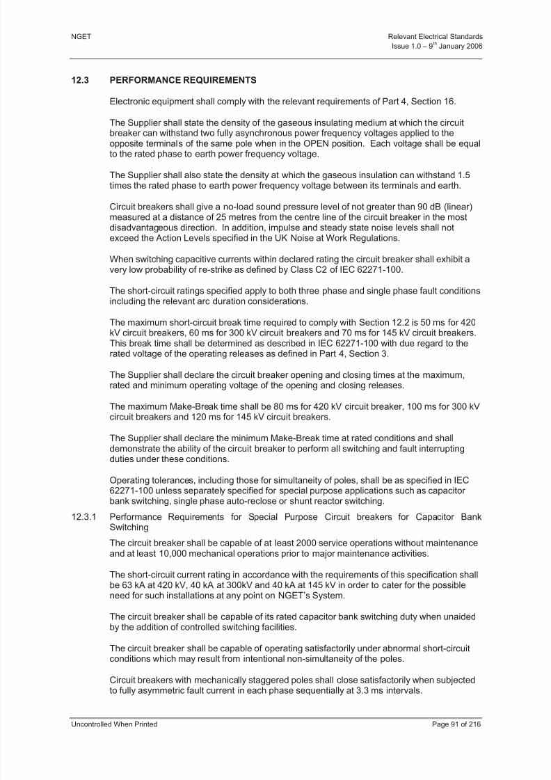
8/3/2019 1 Relevant Standards for Substation Plants
http://slidepdf.com/reader/full/1-relevant-standards-for-substation-plants 98/223
NGET Relevant Electrical Standards
Issue 1.0 – 9th
January 2006
Uncontrolled When Printed Page 91 of 216
12.3 PERFORMANCE REQUIREMENTS
Electronic equipment shall comply with the relevant requirements of Part 4, Section 16.
The Supplier shall state the density of the gaseous insulating medium at which the circuit
breaker can withstand two fully asynchronous power frequency voltages applied to theopposite terminals of the same pole when in the OPEN position. Each voltage shall be equalto the rated phase to earth power frequency voltage.
The Supplier shall also state the density at which the gaseous insulation can withstand 1.5times the rated phase to earth power frequency voltage between its terminals and earth.
Circuit breakers shall give a no-load sound pressure level of not greater than 90 dB (linear)measured at a distance of 25 metres from the centre line of the circuit breaker in the mostdisadvantageous direction. In addition, impulse and steady state noise levels shall notexceed the Action Levels specified in the UK Noise at Work Regulations.
When switching capacitive currents within declared rating the circuit breaker shall exhibit a
very low probability of re-strike as defined by Class C2 of IEC 62271-100.
The short-circuit ratings specified apply to both three phase and single phase fault conditionsincluding the relevant arc duration considerations.
The maximum short-circuit break time required to comply with Section 12.2 is 50 ms for 420kV circuit breakers, 60 ms for 300 kV circuit breakers and 70 ms for 145 kV circuit breakers.This break time shall be determined as described in IEC 62271-100 with due regard to therated voltage of the operating releases as defined in Part 4, Section 3.
The Supplier shall declare the circuit breaker opening and closing times at the maximum,rated and minimum operating voltage of the opening and closing releases.
The maximum Make-Break time shall be 80 ms for 420 kV circuit breaker, 100 ms for 300 kVcircuit breakers and 120 ms for 145 kV circuit breakers.
The Supplier shall declare the minimum Make-Break time at rated conditions and shalldemonstrate the ability of the circuit breaker to perform all switching and fault interruptingduties under these conditions.
Operating tolerances, including those for simultaneity of poles, shall be as specified in IEC62271-100 unless separately specified for special purpose applications such as capacitor bank switching, single phase auto-reclose or shunt reactor switching.
12.3.1 Performance Requirements for Special Purpose Circuit breakers for Capacitor BankSwitching
The circuit breaker shall be capable of at least 2000 service operations without maintenanceand at least 10,000 mechanical operations prior to major maintenance activities.
The short-circuit current rating in accordance with the requirements of this specification shallbe 63 kA at 420 kV, 40 kA at 300kV and 40 kA at 145 kV in order to cater for the possibleneed for such installations at any point on NGET’s System.
The circuit breaker shall be capable of its rated capacitor bank switching duty when unaidedby the addition of controlled switching facilities.
The circuit breaker shall be capable of operating satisfactorily under abnormal short-circuitconditions which may result from intentional non-simultaneity of the poles.
Circuit breakers with mechanically staggered poles shall close satisfactorily when subjectedto fully asymmetric fault current in each phase sequentially at 3.3 ms intervals.
8/3/2019 1 Relevant Standards for Substation Plants
http://slidepdf.com/reader/full/1-relevant-standards-for-substation-plants 99/223
NGET Relevant Electrical Standards
Issue 1.0 – 9th
January 2006
Uncontrolled When Printed Page 92 of 216
The controlled switching system shall be capable of controlling the closing operations of thecircuit breaker such that the point of current initiation coincides with system voltage zero ineach phase with a tolerance of +/-1 ms around the target voltage zero. Where this is not
reliably achievable, and at NGET’s discretion, a wider tolerance of 2 ms may be deemed
acceptable provided that exceedance of the 1 ms requirement is a rare event and can bedemonstrated to occur in less than 2% of cases.
The controlled switching system shall operate consistently and within the tolerances given inthe preceding clause under the following conditions and under any combinations of theseconditions:
At any temperature within the temperature range -100 to +300 C. Separately the Supplier shall state the deviation in performance when operating at temperatures between -100 and -250 C and between +300 and +400 C.
Between consecutive operations at temperatures differing by not more than 200 C within therated ambient temperature range.
At any supply voltage within the range of supply voltages given in Part 4, Section 3.
At any operating mechanism and arc extinguishing medium condition between the closelockout condition and the maximum normal operating condition.
12.4 TEST REQUIREMENTS
12.4.1 Control System Test Requirements
Control system testing shall be in accordance with the requirements of Part 4, Section 16.
12.4.2 Type Test Requirements for Circuit breakers
For general application, asymmetrical current short-circuit interruption tests shall beundertaken with a time constant of 45 ms or greater.
145kV circuit breakers shall also be demonstrated to be capable of operation at a dc timeconstant of 135ms.
Informative: 135ms may be required at bulk supply points and a coincident reduction in RMS current rating e.g. from 40kA to 31.5kA may be acceptable.
Short-circuit testing shall be demonstrated at the minimum operating conditions (lockout)appropriate to the commencement of the duty, i.e. C, O or O-0.3sec-CO. This demonstrationshall confirm the interrupting ability, at open lockout conditions, throughout the full range of arc duration related to single phase fault conditions.
Short-circuit testing shall be demonstrated at the minimum (lockout) conditions of arc
extinguishing and insulating media
In addition to the transient recovery voltage requirements of IEC 62271-100 the following30% short-circuit (T30) TRV characteristics shall be met by 145 kV and 300 kV circuitbreakers.

8/3/2019 1 Relevant Standards for Substation Plants
http://slidepdf.com/reader/full/1-relevant-standards-for-substation-plants 100/223
NGET Relevant Electrical Standards
Issue 1.0 – 9th
January 2006
Uncontrolled When Printed Page 93 of 216
RatedVoltage
(kV)
Current(kA)
TRVpeak,
Uc (kVp)
Time, t3
(µs)
Timedelay, td
(µs)
First
ref voltage,U1 (kVp)
Time, t1 (µs)
Rate of rise,Uc/t
(kV/µs)
145 As T30 285 38 7.6 89 19.5 7.5
300 As T30 415 42 6.0 138 20 10
Proof of ability against the non-mandatory Short Line Fault and Out of Phase requirementsof IEC 62271-100 is required.
General purpose circuit breakers shall be tested for overhead line and cable switching dutiesin accordance with IEC 62271-100. These tests shall demonstrate that the circuit breaker can be categorised as having a very low probability of re-strike (Class C2). The voltagefactor during testing shall be 1.4 for overhead line application and 1.0 for cable applications.Cable switching testing may be waived where circuit breakers are separately tested for capacitor bank switching.
Informative: Capacitive current switching tests shall preferably be performed using full pole,direct test methods.
In order to demonstrate compliance with 12.3, paragraph 4 a no-load sound pressuremeasurement shall be made at a height of 1.2 m above ground level. A pressure transducer shall be used in conjunction with a precision sound level meter which is set to its fastestresponse and linear scale. This will allow direct determination of the overall sound pressurelevel. Because of its short duration the noise is to be recorded on tape so as to enabledetailed harmonic analysis and a check on the instrument reading to be made. Themaximum rms sound pressure levels for each 1/3 octave band is to be determined either bysuccessively playing back the recorded noise through a 1/3 octave band analyser or by useof a real time 1/3 octave analyser.
Since 90 dB measured by the above technique can be achieved with varying frequencyspectra the maximum rms sound pressure level in any 1/3 octave band below a frequency of 1 kHz shall not exceed the maximum rms value in any 1/3 octave band above 1 kHz.
12.4.3 Routine Tests
Routine testing shall comply with IEC 62271-100.
The initial units of circuit breaker/controller systems supplied to NGET for controlledswitching applications shall be subjected to a minimum of 100 operations at a variety of operational conditions such that a limited statistical evaluation of expected performance canbe made.
12.4.4 Site Commissioning Tests
The Supplier shall provide a schedule of site commissioning tests, broadly in accordancewith, and sufficient to show compliance with, IEC 62271-100. The site commissioningprogramme shall include a complete functional check of the control features.
Site commissioning tests on the first 5 units of a design type produced and installed onNGET’s System shall conclude with satisfactory demonstration of 50 operations at ratedconditions. Condition monitoring shall be used to confirm that the final 10 operations showno deterioration in performance.
Following commissioning, but prior to energisation, all circuit breakers shall be subjected to aseries of 25 operations at rated operating conditions.
Circuit breakers intended for switching shunt capacitors and shunt reactors shall besubjected to a series of live switching tests as part of their final commissioning.
8/3/2019 1 Relevant Standards for Substation Plants
http://slidepdf.com/reader/full/1-relevant-standards-for-substation-plants 101/223
NGET Relevant Electrical Standards
Issue 1.0 – 9th
January 2006
Uncontrolled When Printed Page 94 of 216
12.5 DEFINITIONS
12.5.1 General purpose circuit breaker
A circuit breaker for application or connection to the Transmission System in England andWales operating in a normal system role covered by the requirements of IEC 62271-100.Typically this refers to circuit breakers applied to lines, cables, transformers, bus sectionsand bus couplers.
12.5.2 Controlled switching
A method whereby the timing of the operation of a circuit breaker is precisely controlled inrelation to the power frequency supply. Also known as “point-on-wave” switching.
12.5.3 Controlled switching system
The combination of a circuit breaker, controller (relay) and control scheme which, incombination, achieves controlled switching.
12.6 REFERENCES
12.6.1 International, European and British National Documentation
This Document makes reference to the documents listed below.
Noise at Work Regulations 1989.
IEC 62271-100 High-voltage Alternating Current Circuit breakers
BS EN 60694 Common Clauses for High-voltage Switchgear and Controlgear Standards.
IEC 61233 High voltage alternating current circuit breakers - inductive currentswitching.
BS 381C Specification for Colours for Identification, Coding and Special Purposes.
12.7 GUIDANCE NOTES - OPENING AND CLOSING RELEASE LOGIC DIAGRAMS
(This Guidance Note does not form part of the RES document)
The following logic diagrams detail the circuit segregation requirements applicable for thedouble opening release and series closing control schemes for circuit breakers and switches.
Attachment 1 Segregated phases with forced open facility
Attachment 2 Segregated phases with open lockout
Attachment 3 Three phase mechanism with forced open facility
Attachment 4 Three phase mechanism with open lockout
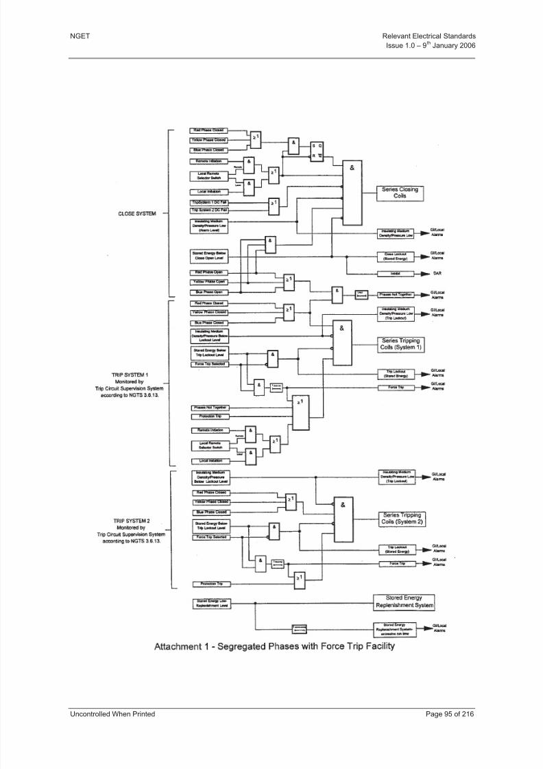
8/3/2019 1 Relevant Standards for Substation Plants
http://slidepdf.com/reader/full/1-relevant-standards-for-substation-plants 102/223
NGET Relevant Electrical Standards
Issue 1.0 – 9th
January 2006
Uncontrolled When Printed Page 95 of 216

8/3/2019 1 Relevant Standards for Substation Plants
http://slidepdf.com/reader/full/1-relevant-standards-for-substation-plants 103/223
NGET Relevant Electrical Standards
Issue 1.0 – 9th
January 2006
Uncontrolled When Printed Page 96 of 216

8/3/2019 1 Relevant Standards for Substation Plants
http://slidepdf.com/reader/full/1-relevant-standards-for-substation-plants 104/223
NGET Relevant Electrical Standards
Issue 1.0 – 9th
January 2006
Uncontrolled When Printed Page 97 of 216
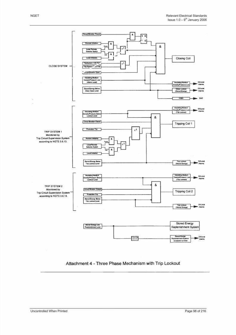
8/3/2019 1 Relevant Standards for Substation Plants
http://slidepdf.com/reader/full/1-relevant-standards-for-substation-plants 105/223
NGET Relevant Electrical Standards
Issue 1.0 – 9th
January 2006
Uncontrolled When Printed Page 98 of 216

8/3/2019 1 Relevant Standards for Substation Plants
http://slidepdf.com/reader/full/1-relevant-standards-for-substation-plants 106/223
NGET Relevant Electrical Standards
Issue 1.0 – 9th
January 2006
Uncontrolled When Printed Page 99 of 216
13 SECTION 10 - DISCONNECTORS AND EARTHING SWITCHES
13.1 PURPOSE AND SCOPE
This Section for disconnectors and earth switches is by reference to IEC 62271-102,
BS EN 60694 and associated documents. This document defines the required enablingparameters and additional technical requirements for disconnectors and earth switches for use on, and directly connected to, the Transmission System in England and Wales, ratedfrom 145 kV to 420 kV.
This document defines the functional performance requirements for disconnectors and earthswitches connected to the Transmission System in England and Wales. It supports the moregeneral conditions defined in Part 4, Sections 1 and Section 3.
13.2 RATINGS AND PERFORMANCE REQUIREMENTS
In addition to the general ratings and performance requirements defined in Part 4, Sections 1and 3, the following ratings apply to disconnectors and earth switches.
Disconnectors and Earth Switches shall satisfy the requirements of IEC 62271-102.
Disconnectors rated at 420 kV and 300 kV shall be motor/power operated.
13.2.1 Rated Short-Time Withstand Current
If an earth switch is combined with a disconnector as a single unit, the rated short-timewithstand current of the earth switch shall be at least equal to that of the disconnector.
13.2.2 Divided Frame Disconnectors and Earthing Switches
Divided frame disconnectors and earth switches shall be capable of operating to the limits of their rated contact zone as detailed in Tables 1 and 2 of IEC 62271-102.
13.2.3 Bus-transfer Duty
Disconnectors intended for bus-transfer or mesh-corner switching shall comply with the bustransfer requirements of IEC 62271-102 Annex B.
Bus transfer switching contacts fitted to disconnectors which can be operated in service froma manual mechanism, shall be designed so that their operation is independent of the speedof operation of the main contacts.
The design of the disconnector shall ensure that the operator is not endangered by arcdebris during bus-transfer switching.
Disconnectors intended for bus-transfer or mesh-corner switching shall comply with the
auxiliary switch requirements for disconnectors with bus transfer duty, as per clause 13.4.6.13.2.4 Rated Values of Mechanical Endurance for Disconnectors
Disconnectors shall be rated to Class M1 as specified in IEC 62271-102.
13.2.5 Rated Values of Electrical Endurance for Earth Switches
Air Insulated Earth Switches shall be rated to Class E0 as specified in IEC 62271-102.
8/3/2019 1 Relevant Standards for Substation Plants
http://slidepdf.com/reader/full/1-relevant-standards-for-substation-plants 107/223
NGET Relevant Electrical Standards
Issue 1.0 – 9th
January 2006
Uncontrolled When Printed Page 100 of 216
13.3 GENERAL REQUIREMENTS FOR DISCONNECTORS AND EARTH SWITCHES
13.3.1 Clearance Distances
Phase-to-phase and phase-to-earth clearance distances shall be as specified in Part 4,Section 2 unless the disconnector or earth switch has been type tested in accordance with
the relevant requirements of IEC 62271-102 for the rated dielectric performance specified inPart 4, Sections 1 and 2. This shall apply to all clearance distances when a disconnector isin any position, including partially operated and for phase-to-phase clearance distance of earth switches in any position including partially operated.
13.3.2 Simultaneous Operation of Poles
The primary contacts of all poles shall operate (open or close) simultaneously, with amaximum spread of 0.5 seconds between first pole contact to open (or close) to the last polecontact to open (or close).
13.3.3 Flexibility of Design and Setting Adjustment Tolerances
All disconnectors and earth switches shall be designed and constructed with enoughflexibility to cater for both coarse and fine adjustments associated with the dimensional
tolerances required to achieve the correct settings under site conditions.
The Supplier shall provide adequate instructions to ensure that the installer is aware of anyrestriction associated with such adjustment. These instructions shall be included in theproduct operating manual.
13.3.4 Position Indication
A clear unambiguous open/closed indication (O/I) label/indicator shall be fitted, identifyingthe position of the main contacts when the operator is operating the disconnector or earthswitch. This indication shall be visible following operation with the control cubicle secure.
For remotely operated disconnectors and earth switches incomplete operation of the maincontacts shall be remotely indicated by a position-indicating device. The position-indicating
device shall be a part of the disconnector or earth switch that enables a signal to be given,generally at a location remote from the disconnector or earth switch. It shall indicate that thecontacts of the main circuit are in the closed or open position and that the mechanicalmovement is complete. This indication shall be repeated at the local control point whenprimary contacts are not readily visible to a local operator.
For GIS disconnectors and earthing switches, a reliable position indicating device (designedin accordance with IEC 62271-102, Annex A) may be provided as an alternative to the visibleisolating distance or gap if easily accessible viewing windows are not provided.
13.3.5 Mechanical Key Interlocking
Where mechanical key interlocking is fitted to disconnector and earth switch mechanisms thefollowing requirements shall apply.
Removal of a key shall, by means of an interference device, physically prevent operation of the mechanism. The interference device shall be so constructed that it will prevent operationwhen a normal operating force is applied by the recommended procedures, whether of power or manual means.
On power operated mechanisms with facilities for in-service manual operation theinterlocking shall be effective for both power and manual operations.
Interlock keys shall be released when the mechanism is in either the fully open or fullyclosed position or both, as required by the interlocking scheme. The keys shall be trappedwhen the mechanism is in a partially operated position.
13.3.6 GIS Combined Disconnectors and Earthing Switches
8/3/2019 1 Relevant Standards for Substation Plants
http://slidepdf.com/reader/full/1-relevant-standards-for-substation-plants 108/223
NGET Relevant Electrical Standards
Issue 1.0 – 9th
January 2006
Uncontrolled When Printed Page 101 of 216
Where a disconnector and earthing switch is combined within a single unit, the disconnector shall be capable of being opened, immobilised and locked before the earthing switch isclosed. It shall not be necessary to unlock the disconnector in order to close the earthingswitch.
Informative: This is to allow primary earths to be applied within the zone established by points of isolation in accordance with NGET Safety rules.
13.3.7 Drive System Mechanical Interference Device
Where no mechanical key interlocking is provided, the drive system shall have a mechanicalinterference device. This device shall be used to physically prevent operation of themechanism when in the open or the closed position. The interference device shall beeffective when any reasonable operating forces are applied by the recommended means,whether by power or manual operation. For NGET Operational and Safety (electrical)reasons facilities shall be provided to lock the interference device in the operated positionusing a padlock with a 5 mm diameter and 30 mm long hasp.
On power operated mechanisms, application of the interference device shall also preventinitiation of the power operation, unless it can be demonstrated no damage will occur as aconsequence of the mechanism being stalled.
13.3.8 'Lockout' Interlock Keys
Lockout interlock keys shall be provided on all 420 kV, 300 kV and 145 kV disconnectors.These keys shall only be released when the disconnector is open.
Lockout interlock keys shall be provided on all 420 kV and 300 kV earth switches and shallonly be released when the earth switch is closed.
Lockout keys shall be distinctively labelled and shall be unique to other keys in use on thesubstation site. The key shall also be unique from the other keys associated with themechanism.
13.3.9 Earthing Switch Magnetic Bolt Device
Earth switches provided with a manual push button to release an electrical magnetic boltdevice within the mechanism shall employ a time delayed magnetic bolt release.
13.3.10 Operations Counter
An operations counter shall be fitted to disconnector drive systems to record the totalnumber of operating cycles (close-open) performed.
13.3.11 Construction Materials and Protective Coatings
The materials used in the construction of disconnectors and earth switches shall bedemonstrated to be satisfactory for the environmental exposure detailed in the normal,special service and pollution conditions of Part 4, Section 1.
13.4 OPERATING MECHANISMS, ANCILLARY EQUIPMENT AND THEIR ENCLOSURES
13.4.1 General
The requirements of Part 4, Section 6 shall apply to disconnector and earth switch operatingmechanisms, ancillary equipment and their enclosures.
13.4.2 'Sealing In' of Control Circuits
When an open or close operation is initiated, the mechanism control scheme shall bedesigned such that the open (or close) control circuit is not 'sealed in' to hold the supplyvoltage on to the drive motor for the duration of the Disconnector or Earth Switch travel, if themotor supply voltage is not available to operate the Disconnector or Earth Switch.
Informative: This is to prevent the condition where a motor supply may not be available, but an Open / Close instruction has been initiated and the control circuit has been latched or
8/3/2019 1 Relevant Standards for Substation Plants
http://slidepdf.com/reader/full/1-relevant-standards-for-substation-plants 109/223
NGET Relevant Electrical Standards
Issue 1.0 – 9th
January 2006
Uncontrolled When Printed Page 102 of 216
'sealed in'. When the motor supply is reinstated, the Disconnector / Earth Switch may unexpectedly operate without checking for valid interlock conditions being present at theactual time of operation.
13.4.3 Drive Limit Switch
Power operated mechanisms shall be designed so that failures of the mechanism limitswitches will not result in damage to the mechanism, drive linkages (with the exception of shear pins or mechanical protective devices) or the primary current path.
13.4.4 Control Switches
Local/Hand/Remote Close control switch shall be provided with a facility for locking in eachposition.
The Open/Neutral/Close control switch shall be provided with a facility for locking in theNeutral position.
13.4.5 Auxiliary Switches
Auxiliary switches shall comply with Part 4, Section 3 and IEC 62271-102. Auxiliary switches
for disconnectors and earth switches are required to have a variety of different timings andsenses with respect to the primary contacts.
The number of each type (i) to (vii) in 13.7 of this Section will be specified on a site-specificbasis.
13.4.6 Auxiliary Switch Requirements for Disconnectors with Bus Transfer Duty
The auxiliary switch variant (vii) in 13.7 is only required on disconnectors for bus transfer duty. This contact timing is used for switching busbar protection CT and tripping circuits.The contact is made available for these specific secondary circuits. The auxiliary contactmust close before the primary contacts start conducting current during a normal closingoperation and must open after the primary contacts have stopped conducting current duringa normal opening operation.
The disconnector positions marked ** in 13.7 shall be established at the time of type testingand recorded in the product operating manual. The setting shall be checked during routine(factory) tests and confirmed when the disconnector is completely assembled on site.
13.5 Test Requirements
The test requirements of Part 4, Section 1, 3 and IEC 62271-102 for disconnectors and earthswitches are appropriate.
The following tests indicated as optional within IEC 62271-102 shall be considered asmandatory to meet the requirements of NGET.
a) Tests to prove satisfactory operation under severe ice conditions.
b) Tests to prove satisfactory operation at minimum and maximum ambient air temperatures.
c) Tests to prove the bus-transfer current switching capability of disconnectors (whereapplicable).
d) Tests to prove the induced current-switching capability of earth switches (whereapplicable).
e) Tests to prove the reliable indicating device in accordance with IEC 62271-102 AnnexA (where applicable).
f) Tests to prove the bus-charging capability of GIS disconnectors in accordance withIEC 62271-102 Annex F (where applicable).
8/3/2019 1 Relevant Standards for Substation Plants
http://slidepdf.com/reader/full/1-relevant-standards-for-substation-plants 110/223
NGET Relevant Electrical Standards
Issue 1.0 – 9th
January 2006
Uncontrolled When Printed Page 103 of 216
13.6 REFERENCES
13.6.1 International, European and British Standard Documents
This document makes reference to the documents listed below. Where a British Standard(BS) has been harmonised into a Euronorm (EN) only this BS EN reference is given. The
issue date of these documents shall be that current at the time of the issue of this TechnicalSpecification.
IEC 62271-102 High Voltage Switchgear and Controlgear. Part 102: High VoltageAlternating Current Disconnectors and Earth switches.
BS EN 60694 Common Specifications for High Voltage Switchgear and Control Gear Standards.
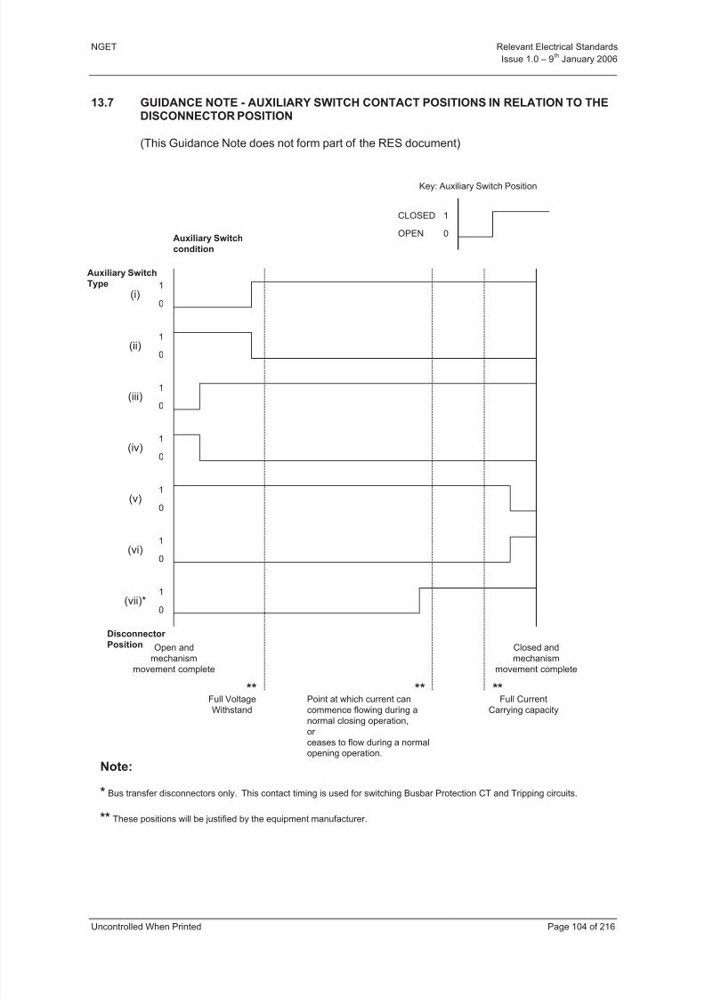
8/3/2019 1 Relevant Standards for Substation Plants
http://slidepdf.com/reader/full/1-relevant-standards-for-substation-plants 111/223
NGET Relevant Electrical Standards
Issue 1.0 – 9th
January 2006
Uncontrolled When Printed Page 104 of 216
13.7 GUIDANCE NOTE - AUXILIARY SWITCH CONTACT POSITIONS IN RELATION TO THEDISCONNECTOR POSITION
(This Guidance Note does not form part of the RES document)
1
0
CLOSED
OPEN
Key: Auxiliary Switch Position
Auxiliary Switch
condition
1
0
1
0
1
0
1
0
1
0
1
0
1
0
(i)
(ii)
(iii)
(iv)
(v)
(vi)
(vii)*
Disconnector
Position Open and
mechanism
movement complete
Closed and
mechanism
movement complete
** ** **Full Voltage
Withstand
Full Current
Carrying capacity
Point at which current can
commence flowing during a
normal closing operation,
or
ceases to flow during a normal
opening operation.
Note:
* Bus transfer disconnectors only. This contact timing is used for switching Busbar Protection CT and Tripping circuits.
** These positions will be justified by the equipment manufacturer.
Auxiliary Switch
Type
8/3/2019 1 Relevant Standards for Substation Plants
http://slidepdf.com/reader/full/1-relevant-standards-for-substation-plants 112/223
NGET Relevant Electrical Standards
Issue 1.0 – 9th
January 2006
Uncontrolled When Printed Page 105 of 216
14 SECTION 11 - CURRENT TRANSFORMERS FOR PROTECTION AND GENERAL USE
14.1 PURPOSE AND SCOPE
This Section defines the functional and performance requirements for current transformers
(CTs) for protection and general use on the Transmission System in England and Wales. Itsupports the more general requirements defined in Part 4, Sections 1, 2 and 3.
This is a functional and performance specification for CTs used for protection andmeasurement application.
14.2 GENERAL REQUIREMENTS
All CTs shall comply with Part 4, Sections 1, 2, 3 and IEC 60044-1. In addition, the followingclauses apply:
14.2.1 General Requirements for all Current Transformers
Additional specification and testing requirements for protection Class PX cores are given in
14.8. For information, these requirements are identical to those given in the now obsoleteBS 3938 Class X sections.
Secondary ratings and transformation ratios shall be selected from the attached Schedulesand shall be specified in the contract Enquiry Document or Supplementary Agreement asappropriate.
A single secondary terminal box shall be mounted on the transformer to accommodate thenecessary secondary terminal connections.
Secondary terminals and connections shall be suitable for their required purpose regardingrating, reliability and the effects of environmental conditions and corrosion.
Secondary terminal boxes shall comply with, as a minumum, the IP54 environment of BS EN60529 as required in Part 4, Section 1.
Primary and secondary terminal markings, and rating plate markings shall be in accordancewith IEC 60044-1
The rated continuous primary current of the current transformer shall be chosen to exceedthe maximum continuous rating of the associated circuit and shall be selected from thestandard values detailed in IEC 60044-1
A thermal short-time current rating (Ith) shall be assigned to all current transformers inaccordance with IEC 60044-1. The value of Ith shall not be less than the corresponding
value for the associated switchgear or transformer primary plant.
Current transformer secondary terminals should allow the application of shorting/earthinglinks or wiring for maintenance purposes. Separately, a terminal for earthing purposes shallbe provided within the terminal box and shall be clearly marked.
For all oil filled CTs the supplier shall declare the type of insulating oil being used.
For oil-filled equipment fitted with an external oil expansion system, means shall be providedto give a permanent visual indication of the volume of the oil. The status of the indicator should be visible from ground level.
For oil filled CTs where the oil expansion system is wholly internal ie gas cushion or flexible
diaphragm, the CT shall be fitted with a permanent internal pressure indicator. The status of the indicator shall be visible from ground level.

8/3/2019 1 Relevant Standards for Substation Plants
http://slidepdf.com/reader/full/1-relevant-standards-for-substation-plants 113/223
NGET Relevant Electrical Standards
Issue 1.0 – 9th
January 2006
Uncontrolled When Printed Page 106 of 216
All oil filled CTs shall be fitted with an oil sample valve, situated at the base of the CT,suitable for taking oil samples for Dissolved Gas Analysis (DGA) in accordance with IEC567. The sample valve shall be situated on the earthed base tank of the CT. Valves wherethe oil is extracted by using a hypodermic needle are not suitable.
Both ends of the CT secondary windings shall be earth free.
14.2.2 Additional Requirements for Post-Type Current Transformers
An insulation test terminal (test tap) shall be provided for the purpose of performing
capacitance and dielectric loss (tan ) measurements of the primary insulation during routinemaintenance. The test terminals shall be suitably identified.
14.2.3 Additional Requirements for Current Transformers for GIS Application
Current transformers may be mounted internally or externally to the GIS enclosure.
Adequate protection against adverse environmental conditions shall be provided for externally mounted CTs as required in Part 4, Section 3.
14.2.4 Additional Requirements for Ring-Type Current Transformers
Current transformers supplied as loose equipment for power transformer application shall beequipped with secondary terminals or shall be supplied with leads of suitable length for thisapplication. Such leads shall be capable of satisfying the test requirement of 14.4.3 (c).
Current transformers supplied with through-wall bushings can be mounted internally or externally to the bushing. Current transformers mounted internally shall be capable of operating within that environment. Current transformers mounted externally shall be suitablyprotected against the effects of adverse environmental conditions as required in Part 4,Section 3.
Current transformers supplied as loose equipment for other switchgear applications shall becapable of operating within that environment. Current transformers for other switchgear
applications, mounted externally, shall be suitably protected against the effects of adverseenvironmental conditions as required in Part 4, Section 3.
14.2.5 Additional Requirements for Measurement/Protection and Class PX Protective CurrentTransformers
Measurement/Protection and class PX protective current transformers with a rated primarycurrent of 2500 A or below and with untapped secondary windings shall have a ratedsecondary current of 1A (as selected from IEC 60044-1). The rated secondary current for current transformers of this primary rating with tapped secondary windings shall be 1 Acorresponding to the highest transformation ratio.
Measurement/Protection and class PX protective current transformers with a rated primarycurrent in excess of 2500 A shall have a rated secondary current selected from the values
stated in IEC 60044-1
14.3 PERFORMANCE REQUIREMENTS
14.3.1 General
All current transformers shall comply with the performance requirements of IEC 60044-1 for the primary ratings detailed in Part 4, Sections 1, 2 and 3. The following requirements shallalso apply as appropriate:
14.3.2 Protection Type PX-A Current Transformers
Protection type PX-A current transformers shall meet the additional requirements given in14.8 providing accurate transformation up to the maximum fault current rating of theassociated main plant. This performance shall be maintained under both fault and steady-
state conditions without saturation

8/3/2019 1 Relevant Standards for Substation Plants
http://slidepdf.com/reader/full/1-relevant-standards-for-substation-plants 114/223
NGET Relevant Electrical Standards
Issue 1.0 – 9th
January 2006
Uncontrolled When Printed Page 107 of 216
Type PX-A current transformers shall also meet the performance requirements of Schedule 2 of this Specification.
14.3.3 Protection Type PX-B Current Transformers
Protection type PX-B current transformers shall meet the additional requirements given in14.8 providing accurate steady-state transformation up to the maximum fault current rating of the associated main plant.
Type PX-B current transformers shall also meet the performance requirements of Schedule 2 of this Specification.
14.3.4 Dual Purpose Measurement/Protection Current Transformers
Current transformers intended for the dual purpose of measurement and protection shallmeet the performance requirements of IEC 60044-1, Clause 14.3.2 and Schedule 2 of thisSpecification.
14.4 TESTING REQUIREMENTS
14.4.1 Type Tests
All current transformers shall be type tested in accordance with IEC 60044-1 (type tests) andIEC 60044-1 (special tests). The additional requirements for protection class PX cores givenin 14.8. Current transformers using a gas insulation system, a leakage test on the gassystem shall be performed by the supplier to demonstrate compliance with Part 4, Section 3.
Radio interference voltage tests to IEC 60694 are to be performed on open-terminal currenttransformers.
A multi chopped impulse test shall be performed on all oil filled current transformers rated72.5 kV and above. The test method is given in 14.7.
Temperature Rise - The thermal time constant of all equipment shall be determined on both
rising and falling temperature.
For oil filled equipment oil samples for DGA shall be taken before and after the dielectric typetests and shall comply with 14.4.4.
Accuracy at Short-Term Continuous Current Levels - Current transformers which have ameasurement specification shall have their errors determined at a current of 12000 A for 420kV rating and 7500 A for 300 kV rating respectively. These currents shall be withstood for aperiod of 3 minutes.
Routine tests shall be performed before and after all type tests.
14.4.2 Routine Tests
All current transformers shall be routine tested in accordance with:
IEC 60044-1 (routine tests)
IEC 60044-1 (special tests)
The additional requirements for protection class PX transformers are given in 14.8.
14.4.3 Additional Routine Tests
a) Accuracy Tests
These shall be performed in a laboratory having traceability to National/Internationalstandards.
8/3/2019 1 Relevant Standards for Substation Plants
http://slidepdf.com/reader/full/1-relevant-standards-for-substation-plants 115/223
NGET Relevant Electrical Standards
Issue 1.0 – 9th
January 2006
Uncontrolled When Printed Page 108 of 216
The overall accuracy and uncertainty of the measurement shall be demonstrated prior to testing and shall be commensurate with the accuracy class of the transformer under test.
Full accuracy routine tests to IEC 60044-1.
b) Capacitance and dielectric loss angle (tan ) measurements of the primary insulationover the voltage range 10 kV to rated voltage shall be performed.
c) Leads for loose current transformers as detailed in Clause 14.2.4 of this Section shallwithstand a power frequency test voltage of 5 kV (peak). For PXA application, the testlevels shall be determined by tests in 14.8.
d) An oil sample for DGA shall be taken as described in 14.4.4 from all oil filled CTs. Thesample shall be taken at least 24 hours after the final routine electrical testing hasbeen performed. The results shall be included in the routine test report as detailed inClause 14.4.4.
14.4.4 Routine Test Reports
Routine test reports shall include details of all routine measurements made in accordancewith this specification. The information regarding the overall accuracy and uncertainty of theaccuracy measurements shall also be recorded.
During the partial discharge (PD) test, the value of measured PD at the specified test voltageshall be recorded together with the value of the PD extinction voltage. Extinction voltage isdefined as the voltage level at which measurable PD is completely extinguished upondecreasing test voltage. The background PD level at the time of the test should also berecorded in the report.
Where oil samples are taken for Dissolved Gas Analysis (DGA) the report shall contain thefollowing information:
a) Name and Address of the laboratory where the analysis was performed
b) The Accuracy, Precision and Detection Limits for the individual gas measurementexpressed in either parts per million (ppm) or percentage by volume.
c) The Sampling Procedure (stating the Standard Method IEC 567 if applicable).
d) The Gas Extraction Method used (stating the Standard Method IEC 567 if applicable).
e) Calibration Procedure adopted by the laboratory, including details of the number of points used over the range (f)and the gases used.
f) Accreditation Status of the laboratory for the purposes of DGA testing.
g) Date Sampled and Analysed.
h) Report the following:
Measurement Units No. Decimal Places
Oil Volume Tested mls 0
Total Gas Content % 2
Hydrogen ppm 0
Methane ppm 0
Ethane ppm 0

8/3/2019 1 Relevant Standards for Substation Plants
http://slidepdf.com/reader/full/1-relevant-standards-for-substation-plants 116/223
NGET Relevant Electrical Standards
Issue 1.0 – 9th
January 2006
Uncontrolled When Printed Page 109 of 216
Ethylene ppm 0
Acetylene ppm 0*
Carbon monoxide ppm 0
Carbon dioxide ppm 0
Oxygen ppm 0
Nitrogen ppm 0
Moisture mg/l 0
*Note: For DGA samples associated with Type Tests, the acetylene value shallbe quoted to one decimal place
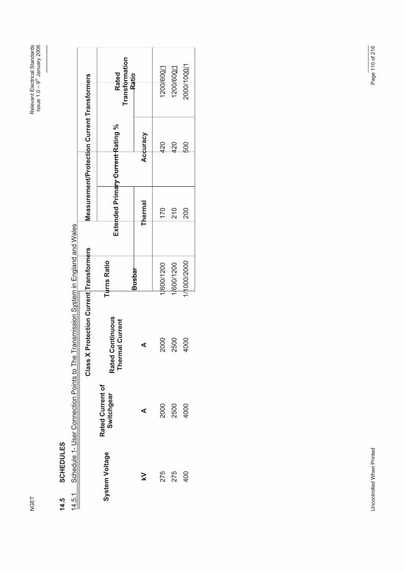
8/3/2019 1 Relevant Standards for Substation Plants
http://slidepdf.com/reader/full/1-relevant-standards-for-substation-plants 117/223
N G E T
R e l e v a n t E l e c t r i c a l S t a n d a r d s
I s s u e 1 . 0 – 9 t h J a n u a r y 2 0 0 6
U n c o n t r o
l l e d W h e n P r i n t e d
P a g e 1 1 0 o f 2 1 6
1 4 . 5
S C H E D U L E S
1 4 . 5 . 1
S c h e d u l e 1 - U s e r C o n n e c t i o n P
o i n t s t o T h e T r a n s m i s s i o n S y s t e m
i n E n g l a n d a n d W a l e s
C l a s s X P r o t e c t i o n C u r r e n t T r a n s f o r m e r s
M e a s u r e
m e n t / P r o t e c t i o n C u r r e n t T r a n s f o r m e r s
T
u r n s R a t i o
S y s
t e m V o l t a g e
R a t e d C u r r e n t
o f
S w i t c h g e a r
R a t e d C o n t i n u o u s
T h e r m a l C u r r e n t
E x t e n d e d P r i m a r y C u r r e n t R a t i n g %
k V
A
A
B u s b a r
T h e r m a l
A c c u r a c y
R a t e d
T r a
n s f o r m a t i o n
R a t i o
2 7 5
2 7 5
4 0 0
2 0 0 0
2 5 0 0
4 0 0 0
2 0 0 0
2 5 0 0
4 0 0 0
1
/ 6 0 0 / 1 2 0 0
1
/ 6 0 0 / 1 2 0 0
1 / 1 0 0 0 / 2 0 0 0
1 7 0
2 1 0
2 0 0
4 2 0
4 2 0
5 0 0
1 2 0 0 / 6 0 0 / 1
1 2 0 0 / 6 0 0 / 1
2
0 0 0 / 1 0 0 0 / 1
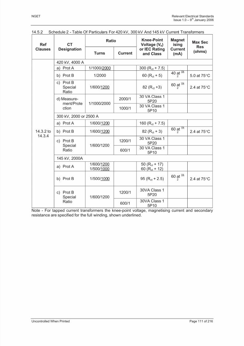
8/3/2019 1 Relevant Standards for Substation Plants
http://slidepdf.com/reader/full/1-relevant-standards-for-substation-plants 118/223
NGET Relevant Electrical StandardsIssue 1.0 – 9
thJanuary 2006
Uncontrolled When Printed Page 111 of 216
14.5.2 Schedule 2 - Table Of Particulars For 420 kV, 300 kV And 145 kV Current Transformers
RatioRef
ClausesCT
DesignationTurns Current
Knee-PointVoltage (Vk)
or IEC Ratingand Class
Magnetising
Current(mA)
Max SecRes
(ohms)
420 kV, 4000 A
a) Prot A 1/1000/2000 300 (Rct + 7.5)
b) Prot B 1/2000 60 (Rct + 5)40 at
Vk
2
5.0 at 75C
c) Prot BSpecialRatio
1/600/1200 82 (Rct +3)60 at
Vk
2
2.4 at 75C
2000/130 VA Class 1
5P20d) Measure-
ment/Protection
1/1000/2000
1000/130 VA Class 1
5P10
300 kV, 2000 or 2500 A
a) Prot A 1/600/1200 160 (Rct + 7.5)
b) Prot B 1/600/1200 82 (Rct + 3)60 at
Vk
2
2.4 at 75C
1200/130 VA Class 1
5P20c) Prot B
SpecialRatio
1/600/1200
600/130 VA Class 1
5P10
145 kV, 2000A
a) Prot A1/600/12001/500/1000
50 (Rct + 17)60 (Rct + 12)
b) Prot B 1/500/1000 95 (Rct + 2.5)60 at
Vk
2 2.4 at 75C
1200/130VA Class 1
5P20
14.3.2 to14.3.4
c) Prot BSpecialRatio
1/600/1200
600/130VA Class 1
5P10
Note - For tapped current transformers the knee-point voltage, magnetising current and secondaryresistance are specified for the full winding, shown underlined.
8/3/2019 1 Relevant Standards for Substation Plants
http://slidepdf.com/reader/full/1-relevant-standards-for-substation-plants 119/223
NGET Relevant Electrical StandardsIssue 1.0 – 9
thJanuary 2006
Uncontrolled When Printed Page 112 of 216
14.6 REFERENCES
14.6.1 International, European and British National Documentation
This document makes reference to, or should be read in conjunction with, the documentslisted below. Where a standard has been harmonised into a Euronorm, only this latter
reference is given. The issue and date of the documents detailed below shall be applicableat the time of issue of this specification unless a specific issue date is given
IEC 60044-1 Instrument transformers- Part 1: Current Transformers
IEC 567 Guide for the sampling of gases and of oil from oil filled electricalequipment and for the analysis of free and dissolved gases.
IEC 60044-6 Requirements for protective Current Transformers for transientperformance
BS EN 60694 Common specifications for high voltage switchgear and controlgear standards
BS 7626 Current Transformers
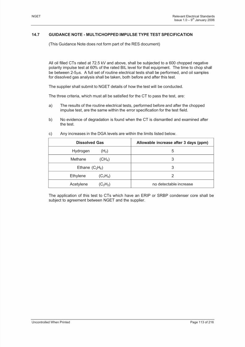
8/3/2019 1 Relevant Standards for Substation Plants
http://slidepdf.com/reader/full/1-relevant-standards-for-substation-plants 120/223
NGET Relevant Electrical StandardsIssue 1.0 – 9
thJanuary 2006
Uncontrolled When Printed Page 113 of 216
14.7 GUIDANCE NOTE - MULTICHOPPED IMPULSE TYPE TEST SPECIFICATION
(This Guidance Note does not form part of the RES document)
All oil filled CTs rated at 72.5 kV and above, shall be subjected to a 600 chopped negativepolarity impulse test at 60% of the rated BIL level for that equipment. The time to chop shall
be between 2-5s. A full set of routine electrical tests shall be performed, and oil samplesfor dissolved gas analysis shall be taken, both before and after this test.
The supplier shall submit to NGET details of how the test will be conducted.
The three criteria, which must all be satisfied for the CT to pass the test, are:
a) The results of the routine electrical tests, performed before and after the choppedimpulse test, are the same within the error specification for the test field.
b) No evidence of degradation is found when the CT is dismantled and examined after the test.
c) Any increases in the DGA levels are within the limits listed below.
Dissolved Gas Allowable increase after 3 days (ppm)
Hydrogen (H2) 5
Methane (CH4) 3
Ethane (C2H6) 3
Ethylene (C2H4) 2
Acetylene (C2H2) no detectable increase
The application of this test to CTs which have an ERIP or SRBP condenser core shall besubject to agreement between NGET and the supplier.

8/3/2019 1 Relevant Standards for Substation Plants
http://slidepdf.com/reader/full/1-relevant-standards-for-substation-plants 121/223
NGET Relevant Electrical StandardsIssue 1.0 – 9
thJanuary 2006
Uncontrolled When Printed Page 114 of 216
14.8 GUIDANCE NOTE - ADDITIONAL REQUIREMENTS FOR PROTECTION CLASS PXTRANSFORMERS
(This Guidance Note does not form part of the RES document)
Within the scope of IEC 60044-1 paragraph 5 additional requirements may be specified for certain protective systems. The specification and tests for Class PX transformers wasaddressed in BS 3938. This document was withdrawn in June 1998. The followingamendment has been tabled by the United Kingdom BSI PEL 38 Instrument Transformer Technical Committee for inclusion IEC 60044-1 addressing these requirements.
The numbering of this section is identical to the submission made to IEC. When theamendment has been incorporated into IEC 60044-1 this document will be revised.
B1.1 Scope
Modify 5th paragraph
For certain protective systems, ........resonant earthed networks), additional requirements aregiven in Clause 14 for class PX transformers.
After 5th paragraph add
Clause 14 covers the requirements and tests in addition to those in clauses 3 to 10 that arenecessary for current transformers for use with electrical protective relays, and in particular for forms of protection for which knowledge of the transformer secondary excitationcharacteristic, secondary winding resistance, secondary burden resistance and turns ratio issufficient to assess its performance in relation to the protective relay system with which it isto be used.
B1.2 Normative references
Add
44-6 (1992) :instrument transformers, Part 6 : Requirements for protective currenttransformers for transient performance
B2 Definitions
B2.1 General definitions
Add
B2.1.32 rated resistive burden (R b ) : For definition see IEC Publication 60044-6 Clause 3.11.
B2.1.33 secondary winding resistance (R ct ) : For definition see IEC Publication 60044-6Clause 3.12.
B2.3 Additional definitions for protective current transformers.
B2.3.10 Excitation characteristic : A graphical or tabular presentation of the relationship betweenthe r.m.s value of the exciting current and a sinusoidal r.m.s e.m.f applied to the secondaryterminals of a current transformer, the primary and other windings being open circuited, over a range of values sufficient to define the characteristics from low levels of excitation up to the
rated knee point e.m.f.
8/3/2019 1 Relevant Standards for Substation Plants
http://slidepdf.com/reader/full/1-relevant-standards-for-substation-plants 122/223
NGET Relevant Electrical StandardsIssue 1.0 – 9
thJanuary 2006
Uncontrolled When Printed Page 115 of 216
B2.3.12 Rated knee point e.m.f (E k ) : That minimum sinusoidal e.m.f. (r.m.s) at rated power
frequency when applied to the secondary terminals of the transformer, all other terminalsbeing open-circuited, which when increased by 10% causes the r.m.s exciting current toincrease by no more than 50%.
Note: - The actual knee point e.m.f will be the rated knee point e.m.f.
B2.3.13 Rated turns ratio : The required ratio of the number of primary turns to the number of secondary turns eg
Example 1: 1/ 600 (one primary turn with six hundred secondary turns)
Example 2: 2/1200 (a current transformer of similar ratio to example 1 but employing twoprimary turns).
B2.3.14 Turns ratio error: The difference between the rated and actual turns ratios. expressed as apercentage.
Turns ratio error (%) = (actual turns ratio - rated turns ratio) × 100
rated turns ratio
B6 Classification of tests
B6.1 Type tests
Modify as follows :
(f) determination of errors (see 11.4 and/or 12.4, 11.6, 12.5, 14.3)
B6.2 Routine tests
Modify as follows :
(d) power-frequency withstand test on secondary winding ( see 8.3 or 14.4.4);
(e) power-frequency withstand tests, between sections ( see 8.3 or 14.4.4 );
(f) inter-turn over voltage test (see 8.4 or 14.4.5);
(g) determination of errors (see 11.5 and/or 12.4, 11.6, 12.6, 14.4)
B10.2 Rating plate markings
Modify as follows :
(e) The rated output and the corresponding accuracy class, together with additionalinformation specified in the later parts of these recommendations (see 11.7 and/or 12.7, 13.8, 14.5).
B14 Additional requirements for Class PX protective current transformers
B14.1 Specification of performance for Class PX protective current transformers:
The performance of class PX current transformers shall be specified in terms of thefollowing:
(a) rated primary current (Ipn)
(b) rated secondary current (Isn)
8/3/2019 1 Relevant Standards for Substation Plants
http://slidepdf.com/reader/full/1-relevant-standards-for-substation-plants 123/223
NGET Relevant Electrical StandardsIssue 1.0 – 9
thJanuary 2006
Uncontrolled When Printed Page 116 of 216
(c) rated turns ratio. The turns ratio error shall not exceed ± 0.25%
(d) rated knee point e.m.f. (Ek)

8/3/2019 1 Relevant Standards for Substation Plants
http://slidepdf.com/reader/full/1-relevant-standards-for-substation-plants 124/223
NGET Relevant Electrical StandardsIssue 1.0 – 9
thJanuary 2006
Uncontrolled When Printed Page 117 of 216
(e) maximum exciting current (Ie) at the rated knee point e.m.f. and / or at a stated
percentage thereof
(f) maximum resistance of the secondary winding at a temperature of 75°C (Rct)
(g) rated resistive burden (Rb)
(h) dimensioning factor (Kx)
Note - The rated knee point e.m.f. is generally determined as follows:
snbct xk I R R K E
B14.2 Insulation requirements for class PX protective current transformers.
B14.2.1 Insulation requirements for secondary winding
The secondary winding insulation of class PX current transformers having a rated knee pointvoltage Ek 2 kV shall be capable of withstanding a rated power frequency withstandvoltage of 5 kV r.m.s for 60 s. For Ek < 2 kV the withstand voltage shall be 3 kV r.m.s for 60s.
B14.2.2 Inter-turn insulation requirements
For Class PX transformers having a rated knee point e.m.f of 450 V or less the rated withstandvoltage for inter-turn insulation shall be 4.5 kV peak. For those with a rated knee point e.m.f of greater than 450V, the rated withstand voltage for the inter-turn insulation shall be a peak voltage of 10 timesthe r.m.s value of the specified knee point e.m.f, or 10 kV peak, whichever is the lower. Note: For some EHV transmission systems a higher limiting value of peak voltage may be agreed between the
manufacturer and the purchaser.
B14.3 TYPE TESTS FOR CLASS PX PROTECTIVE CURRENT TRANSFORMERS
Class PX current transformers shall in addition to the requirements of clause 7 be tested as below.
B14.3.1 Proof of low reactance type
An inspection of drawings shall be made in accordance with the requirements of IECPublication 60044-6 Clause 7.3.1 a) in order to establish proof of low leakage reactancedesign. If compliance with the requirements of low leakage reactance design cannot beestablished to the mutual satisfaction of the manufacturer and purchaser by reference todrawings then the composite error shall be determined for the complete secondary winding
using either of the direct methods of test given in Appendix A Clause A.5 or A.6 of thisdocument, at a secondary current of Kx. Isn and with a secondary burden Rb. Proof of lowleakage reactance design shall be considered to have been established if the value of composite error from the direct method of test is less than 1.1times that deduced from thesecondary excitation characteristic.
Note - The value of primary current required to perform direct composite error tests on certaintransformer types may be beyond the capability of facilities normally provided by manufacturers. Testsat lower levels of primary current may be agreed between the manufacturer and purchaser.
B14.4 ROUTINE TESTS FOR CLASS PX PROTECTIVE CURRENT TRANSFORMERS
Class PX current transformers shall in addition to the requirements of clause 8 be tested as below:
8/3/2019 1 Relevant Standards for Substation Plants
http://slidepdf.com/reader/full/1-relevant-standards-for-substation-plants 125/223
NGET Relevant Electrical StandardsIssue 1.0 – 9
thJanuary 2006
Uncontrolled When Printed Page 118 of 216
B14.4.1 Rated knee point e.m.f. (E k ) and maximum exciting current (I e )
A sinusoidal e.m.f. of rated frequency equal to the rated knee-point e.m.f. shall be applied to thecomplete secondary winding, all other windings being open-circuited and the exciting currentmeasured.
The e.m.f. shall then be increased by 10% and the exciting current shall not increase by more than50%. All measurement shall be performed using r.m.s. measuring instruments. Due to the nonsinusoidal nature of the measured quantities the measurements should be performed using r.m.smeasuring instruments having a crest factor 3.
The excitation characteristic shall be plotted at least up to the rated knee point e.m.f. The excitingcurrent (I'e) at the rated knee-point e.m.f. and at any stated percentage, shall not exceed the rated
value. The number of measurement points shall be agreed between the manufacturer and thepurchaser.
B14.4.2 Secondary winding resistance (Rct)
The resistance of the complete secondary winding shall be measured. The value obtained whencorrected to 75°C shall not exceed the specified value.
B14.4.3 Turns ratio error ( t)
The turns ratio shall be determined in accordance with IEC publication 60044-6 Annex E. The turnsratio error shall not exceed the value given in Clause 14.1 (c).
Note - A simplified test involving measurement of the ratio error with zero connected burden may besubstituted by agreement between the manufacturer and purchaser.
B14.4.4 Insulation tests
Tests shall be performed to demonstrate compliance with Clause 14.2.1 . For test method refer toClause 8.3.
B14.4.5 Inter-turn insulation tests
Tests shall be performed to demonstrate compliance with Clause 14.2.2. For test methodrefer to Clause 8.4
B14.5 MARKING OF RATING PLATE OF CLASS PX CURRENT TRANSFORMERS
B14.5.1 Principal marking : See Clauses 10.2.
B14.5.2 Special marking
(a) rated turns ratio
(b) rated knee point e.m.f. (Ek)
(c) maximum exciting current (Ie) at the rated knee point e.m.f. and/or at the stated
percentage thereof.
(d) maximum resistance of the complete secondary winding at a temperature of 75°C (R
ct)
The following may also be required by the purchaser:
8/3/2019 1 Relevant Standards for Substation Plants
http://slidepdf.com/reader/full/1-relevant-standards-for-substation-plants 126/223
NGET Relevant Electrical StandardsIssue 1.0 – 9
thJanuary 2006
Uncontrolled When Printed Page 119 of 216
(e) dimensioning factor (Kx)
(f) rated resistive burden (Rb)
8/3/2019 1 Relevant Standards for Substation Plants
http://slidepdf.com/reader/full/1-relevant-standards-for-substation-plants 127/223
NGET Relevant Electrical StandardsIssue 1.0 – 9
thJanuary 2006
Uncontrolled When Printed Page 120 of 216
15 SECTION 12 - BUSHINGS
15.1 PURPOSE AND SCOPE
This Specification defines the functional and performance requirements for bushings on the
Transmission System in England and Wales. It supports the more general requirementsdefined in Part 4, Sections 1 and 3.
This document details the functional performance and test characteristics for bushings for connection to the Transmission System in England and Wales.
15.2 GENERAL REQUIREMENTS
Bushings shall comply with the requirement stipulated in Part 4, Sections 1 and 3.
Bushings shall comply with BS EN 60137.
Bushings with capacitance grading shall be provided with a test terminal (test tap) as defined
in BS EN 60137.
For bushings containing oil, an indicator to check the correct amount of oil is in theequipment should be provided (generally a sight glass).
All oil-filled equipment shall be fitted with an oil sample valve, situated on the earth flange,suitable for taking oil samples for Dissolved Gas Analysis (DGA) in accordance withIEC 567. Valves where the oil is extracted by using a hypodermic needle are notacceptable.
For oil impregnated paper bushings, the bushing design shall have sufficient oil capacity toallow 1 litre of oil to be extracted over the lifetime of the bushing for dissolved gas analysispurposes. Alternatively the supplier shall provide instructions on how to replenish the
bushing with oil.
15.3 PERFORMANCE REQUIREMENTS
Bushings shall comply with the performance requirements of BS EN 60137 according to therelevant rating requirements detailed in Part 4, Sections 1 and 3.
15.4 TYPE TEST REQUIREMENTS
Bushings shall be type tested to BS EN 60137.
During the Temperature Rise Test the thermal time constant shall be determined on raisingand lowering the temperature.
An oil sample for DGA shall be taken from all oil filled bushings, before and after thedielectric type tests. Acceptance criteria for the dissolved gas levels in oil will be agreedbetween NGET and the bushing supplier. There shall be no change in the dissolved gaslevels before and after type tests.
15.5 ADDITIONAL TYPE TEST FOR BUSHINGS OF THE CAPACITIVELY GRADED TYPE
Bushings for all switchgear applications shall have chopped impulse tests similar to thosespecified for transformer bushings in BS EN 60137. The bushings shall be subjected to 5impulses of negative polarity, chopping of the impulse being made by means of an air insulated gap. The peak voltage level shall be 100% of the rated BIL. The time to sparkover
of the chopping gap shall be between 1 µs and 6 µs.

8/3/2019 1 Relevant Standards for Substation Plants
http://slidepdf.com/reader/full/1-relevant-standards-for-substation-plants 128/223
NGET Relevant Electrical StandardsIssue 1.0 – 9
thJanuary 2006
Uncontrolled When Printed Page 121 of 216
Bushings for gas insulated switchgear shall also be subjected to 30 impulses of both positiveand negative polarities with a chopping gap immersed in SF6 and located adjacent to the SF6 end of the bushing. The peak voltage level shall be 60% of the rated BIL. The time tosparkover of the chopping gap shall be between 1 µs and 6 µs.
Routine tests shall be performed before and after all type tests.
15.6 ROUTINE TEST REQUIREMENTS
All bushings shall be routine tested to BS EN 60137.
An oil sample for DGA shall be taken not less than 24 hours after the final routine electricaltesting has been performed. The results shall be included in the routine test report.
Routine test reports shall include details of all routine measurements made in accordancewith this specification.
Specifically for partial discharge (PD) tests, the values of measured PD at the specified
partial discharge test voltage shall be recorded together with PD extinction voltages. Thebackground PD level at the time of the test should also be recorded in the report.
Informative: Extinction voltage is defined as the voltage level at which measurable PD isextinguished upon decreasing test voltage
15.7 REFERENCES
15.7.1 International, European and British National Documentation
This document makes reference to or should be read in conjunction with the documentslisted below. Where a Standard has been harmonised into a Euronorm, only this latter reference is given. The issue and date of the documents detailed below shall be thatapplicable at the time of issue of this specification unless a specific issue date is given.
BS EN 60137 Bushings for Alternating Voltages Above 1000V
BS EN 60694 Common Clauses for High-voltage Switchgear and Controlgear Standards
IEC 255-23 Electrical Relays - Part 23: Contact Performance
BS EN 60517 Gas Insulated Metal Enclosed Switchgear for Rated Voltages of 72.5kVand Above
IEC 60815 Guide for the selection of insulators in respect of polluted conditions.
IEC 60567 Guide for the sampling of gases and of oil from oil filled electricalequipment and for the analysis of free and dissolved gases.

8/3/2019 1 Relevant Standards for Substation Plants
http://slidepdf.com/reader/full/1-relevant-standards-for-substation-plants 129/223
NGET Relevant Electrical StandardsIssue 1.0 – 9
thJanuary 2006
Uncontrolled When Printed Page 122 of 216
16 SECTION 13 - SOLID CORE POST INSULATOR FOR SUBSTATIONS
16.1 PURPOSE AND SCOPE
These requirements for solid core post insulators are by reference to IEC 60273, IEC 60168
and associated documents. This document defines the required enabling parameters andadditional technical requirements for solid core post insulators for use on, and directlyconnected to, the Transmission System in England and Wales, rated from 1kV to 420kV.
This document defines the functional performance requirements for solid core post insulatorsconnected to the Transmission System in England and Wales. It supports the more generalconditions defined in Part 4, Sections 1 and 3.
16.2 RATINGS AND PERFORMANCE REQUIREMENTS
In addition to the general ratings and performance requirements defined in Part 4, Sections 1and 3, the following ratings apply to post insulators.
Post insulators shall satisfy the requirements in IEC 60273.
16.3 TEST REQUIREMENTS
16.3.1 Type Tests
Type tests shall be as required in Part 4, Sections 1and 3, together with the requirements of IEC 60168. Where the purchaser is presented with test options within IEC 60168, thefollowing apply;
16.3.2 Dry Lightning-Impulse Withstand Voltage Test
Either test method described in IEC 60168 is acceptable.
16.3.3 Dry Or Wet Switching-Impulse Withstand Voltage Test
Either test method described in IEC 60168 is acceptable.
16.3.4 Mechanical Failing Load Tests
In addition to the bending test, the tensile and torsion tests shall be performed during typetesting as described in IEC 60168.
16.3.5 Test for Deflection Under Load
This test shall be performed during type tests to establish the top flange deflection obtainedas a result of applying 70% of the specified mechanical failing load.
16.3.6 Radio Interference Test
This special test shall be performed as described in IEC 60168 and IEC 60437.
16.3.7 Sample Testing
Sample testing requirements are dependant on production quantity and other commercialconsiderations. Where sample testing is required it shall be as detailed in IEC 60168 andPart 4, Section 1, with any site specific requirements being detailed in the Contract EnquiryDocument or Supplemental Agreement.
16.3.8 Routine Testing
Routine tests shall be as required in Part 4, Sections 1 and 3 together with the requirementsof IEC 60168.

8/3/2019 1 Relevant Standards for Substation Plants
http://slidepdf.com/reader/full/1-relevant-standards-for-substation-plants 130/223
NGET Relevant Electrical StandardsIssue 1.0 – 9
thJanuary 2006
Uncontrolled When Printed Page 123 of 216
16.4 REFERENCES
16.4.1 International, European and British National Documentation
This document makes references to, and should be read in conjunction with the documentslisted below. Where a British Standard (BS) has been harmonised into a Euronorm (EN)
only this BS EN reference is given.
IEC 60273 Characteristics of indoor and outdoor post insulators and post insulator units for systems with nominal voltages greater than 1000V.
IEC 60168 Tests on indoor and outdoor post insulators of ceramic material or glassfor systems with nominal voltages greater than 1000V.
IEC 60437 Radio interference tests on high voltage insulators.
IEC 60694 Common Specifications for High Voltage Switchgear and Control Gear Standards.
IEC 815 Guide for the selection of insulators in respect of polluted conditions.

8/3/2019 1 Relevant Standards for Substation Plants
http://slidepdf.com/reader/full/1-relevant-standards-for-substation-plants 131/223
NGET Relevant Electrical StandardsIssue 1.0 – 9
thJanuary 2006
Uncontrolled When Printed Page 124 of 216
17 SECTION 14 - BUSBAR PROTECTION
17.1 SCOPE
This Section describes the functional and performance requirements and the facilities to be
provided for the numerical protection of busbars at 400 kV, 275 kV and 132 kV doublebusbar switching stations.
17.2 REFERENCES
This Specification makes reference to a Domain Diagram showing relevant bay levelspecification functionality linked to the following documents:
IEC 255-1-00 - All or Nothing Electrical Relays.
IEC 255-6 - Measuring Relays and Protection Equipment.
IEC 255-13 - Biased Differential Relays.
17.3 FUNCTIONAL REQUIREMENTS
17.3.1 Busbar Protection System
Numerical busbar protection shall provide fully discriminative protection for phase-to-phaseand phase-to-earth faults occurring within the substation.
Where the primary arrangement of the substation permits the substation to be split into anumber of sections delimited by circuit breakers or disconnectors, the numerical busbar protection shall provide fully discriminative protection for phase-to-phase and phase-to-earthfaults occurring within each section.
Separate protection zones shall be provided for each busbar section.
The numerical busbar protection shall discriminate between faults in the protected busbar section and faults elsewhere in the substation or the primary system.
The busbar protection shall employ a minimum of two different fault detection algorithms thatmust both be satisfied for tripping to occur.
If a biased differential principle is used, the protection shall comply with the requirements of IEC 255-13.
The operating current of the busbar protection shall be settable in the range 50 – 600% of 2000 amps at 400 kV or 50 – 600% of 1000 amps at 275 and 132 kV.
When a busbar fault occurs, all circuit breakers connected to the faulted busbar shall betripped simultaneously, whether they can feed fault current or not.
The busbar protection shall be able to due correctly detect a fault condition occurring duringan on-load busbar changeover and issue trip commands to the connected bays.
17.3.2 Switchgear Positional Information
Where a fault occurs in the overlap between two zones, e.g. at a Bus-section or Bus-coupler,with the circuit breaker closed, both zones shall be tripped simultaneously.
Switchgear positional information shall be used to determine the primary arrangement of each busbar section.
8/3/2019 1 Relevant Standards for Substation Plants
http://slidepdf.com/reader/full/1-relevant-standards-for-substation-plants 132/223
NGET Relevant Electrical StandardsIssue 1.0 – 9
thJanuary 2006
Uncontrolled When Printed Page 125 of 216
Where a discrepancy (DBI) in switchgear positional information occurs, the busbar protectionshall have user selectable options either to remain in service using the last verifiedswitchgear position or to block protection operation for the affected zone.
17.3.3 Differential Current Supervision
Differential current supervision shall be provided on each zone.
The differential current supervision shall be settable in the range 2 to 10% of 2000 amps at400 kV, 2 to 10% of 1000 amps at 275 kV and 132 kV.
Where operation of the differential current supervision occurs, the busbar protection shallhave user selectable options either to remain in service or to block protection operation.
Operation of the differential current supervision shall generate an alarm after a time delaysettable in the range 0 - 10 s.
17.3.4 Physical Arrangement
The functionality shall be implemented in accordance with Transmission System in Englandand Wales requirements as applied to the site being connected to.
The system shall consist of a distributed set of bay units and a single central unit.
Informative: A typical arrangement of bay units and a single central unit is shown inFigure 10.
The protection shall collect current and switchgear positional information at the bay units.
Bay units shall preferably be mounted with the bay secondary equipment.
The central unit shall perform the busbar protection algorithm using the current andpositional information transmitted from the bay units.
The central unit shall transmit tripping commands to the required bay units to operate therequired outputs.
Communications between bay units and central unit shall be immune to electrical noise.
Separate multicore cables shall be employed and the wiring and terminals shall, as far asreasonably practicable, be segregated from other circuits.
The auxiliary supply to each bay unit shall be provided from the 110 V (dc) first trippingsupply for the bay.
The auxiliary supply to each bay unit shall not be separately fused or protected.
The auxiliary supply to the central unit shall be taken from the 110 V (dc) supply.
Informative: It is preferred that the central unit have duplicated energising supplies withautomatic changeover facility.
The equipment for busbar protection shall be electrically and physically independent fromother equipment, as far as practicable.
17.3.5 Interfaces
Informative: Figure 11 shows the interfaces to a typical bay unit.
17.3.6 Current Transformer Inputs
There shall be one current transformer input for each bay except that bus section and buscoupler bays shall have a current transformer input from each side of the circuit breaker.
8/3/2019 1 Relevant Standards for Substation Plants
http://slidepdf.com/reader/full/1-relevant-standards-for-substation-plants 133/223
NGET Relevant Electrical StandardsIssue 1.0 – 9
thJanuary 2006
Uncontrolled When Printed Page 126 of 216
Informative: Figure 10 shows one bay unit for each three-phase set of current transformer inputs and, hence, two bay units are shown for a bus-section or bus-coupler bay.
The busbar protection system shall be capable of operating from Measurement/Protectioncurrent transformers as defined in Part 4, Section 11.
The busbar protection system shall be capable of accepting inputs from current transformershaving different ratios in different bays.
There shall be no auxiliary switch contacts or relay contacts in the current transformer circuits.
17.3.7 In/Out Switching
A local in/out switching facility shall be provided to enable each bay unit to be taken out of service whilst the remainder of the busbar protection remains in service.
The in/out switching facility shall be activated by a control input as specified by NGET and asused for the control of busbar protection at the connection site.
The in/out switching facility shall be common for all the functions resident in the bay unit.
A secure means shall be provided to activate the In/Out of service switching facility e.g. keyswitch.
Activation of the in/out switching facility shall set the bay unit outputs to the stateprogrammed by the user as a setting.
In/Out switching functions shall be latched in the last selected position.
17.3.8 Switchgear Positional Information
Switchgear positional information shall be determined by double point inputs as specified by
NGET and as used for the control of busbar protection at the connection site.
Discrepancies in switchgear positional information shall generate an alarm after a time delaysettable in the range 0 - 10 s.
17.3.9 Outputs
Each bay unit shall provide a minimum of three single point outputs as specified by NGETand as used for the busbar protection outputs at the connection site., for tripping, twooperating from the busbar protection and one from the circuit breaker fail protection.
Each bay unit shall provide the following alarm outputs:-
a) Disconnector Auxiliary Switch discrepancy alarm.
b) Equipment inoperative, for the loss of dc auxiliary energising supply and internal relayfailures.
c) Bay unit out of service.
Informative: Figure 12 shows the interfaces to a typical central unit.
The central unit shall provide the following alarm outputs:-
a) Busbar protection zone operation.
b) Differential current supervision.
c) Disconnector Auxiliary Switch discrepancy alarm.
8/3/2019 1 Relevant Standards for Substation Plants
http://slidepdf.com/reader/full/1-relevant-standards-for-substation-plants 134/223
NGET Relevant Electrical StandardsIssue 1.0 – 9
thJanuary 2006
Uncontrolled When Printed Page 127 of 216
d) Equipment inoperative, for the loss of dc auxiliary energising supply and internal relayfailures.
17.3.10 Informative Interface
In addition to the requirements for the Informative Interface specified by NGET and as usedfor the interface at the connection site. the Bay Unit shall provide the following information:
a) Fault type, e.g. R – E or Y – B.
b) Phase currents.
c) Records of recent faults shall be stored and be available for downloading either locallyor remotely.
In addition to the requirements for the Informative Interface specified by NGET and as usedfor the central unit at the connection site. the Central Unit shall provide the followinginformation:
a) Faulted zone.
b) Fault type, e.g. R – E or Y – B.
c) Current substation configuration.
d) Differential currents for each zone.
e) Records of recent faults shall be stored and be available for downloading either locallyor remotely.
17.3.11 Man Machine Interface
The following indications shall be provided on the bay units;
a) Protection operated.
The following indications shall be provided on the central unit.
b) Protection operated.
17.4 PERFORMANCE REQUIREMENTS
The protection system shall perform correctly in accordance with the requirements of thisSpecification for the range of power system conditions specified in Part 4, Section 1 and therange of environmental conditions specified by NGET and as used for the busbar protectionat the connection site.
The protection system shall perform correctly under the conditions of current transformer saturation and magnetising inrush.
17.4.1 Accuracy
The accuracy of the busbar protection shall be such that, when set appropriately, and over the range of conditions referred to, it shall perform correctly and in accordance with thisspecification.
The accuracy shall not be affected by more than 10 % ( 2 % for auxiliary power supplyvariations) under the range of system and atmospheric conditions specified in Part 4,Section 1.
17.4.2 Reliability
8/3/2019 1 Relevant Standards for Substation Plants
http://slidepdf.com/reader/full/1-relevant-standards-for-substation-plants 135/223
NGET Relevant Electrical StandardsIssue 1.0 – 9
thJanuary 2006
Uncontrolled When Printed Page 128 of 216
Upon recovery of the input energising supply from a failure condition, the full discriminativeprotection system shall come into operation within 10 s.
17.4.3 Operating Time
The operating time of the busbar protection shall be not greater than 30 ms.
The resetting time of the busbar protection shall be not greater than 50 ms.
Where a change of setting, a configuration change or other software change requires thebusbar protection to be switched out of service, the period of non-availability shall notexceed 15 minutes.
17.5 TESTING
17.5.1 Power System Conditions
The busbar protection shall be demonstrated to operate correctly for the range of systemfault infeeds, X/R ratios, balanced and unbalanced load currents, offsets, voltage levels,shunt capacitance currents, harmonic currents, oscillatory currents, resonance conditionsand travelling wave effects that are defined in Part 4, Section 1.
The busbar protection shall be demonstrated to operate correctly under the conditions of current transformer saturation and inrush.
17.5.2 Protection System Characteristics
The characteristics of the busbar protection and its accuracy and repeatability shall bedemonstrated.
The presentation of these characteristics shall make it possible to verify that the performancemeets the requirements as specified in 17.4.
17.5.3 Operating Time
The requirements of 17.4.3 shall be demonstrated for the range of influencing quantities asspecified and over a reasonable range of settings.

8/3/2019 1 Relevant Standards for Substation Plants
http://slidepdf.com/reader/full/1-relevant-standards-for-substation-plants 136/223
NGET Relevant Electrical StandardsIssue 1.0 – 9
thJanuary 2006
Uncontrolled When Printed Page 129 of 216
Figure 10 – Typical Block Diagram of Connections for Numerical Busbar Protection
B/C
Bay Unit
1
B/C
Bay Unit
2
Feeder
Bay Unit
B/S
Bay Unit
1
B/S
Bay Unit
2
Feeder
Bay Unit
Central Unit
INPUT TO BAY UNIT
FIBRE OPTIC CONNECTION
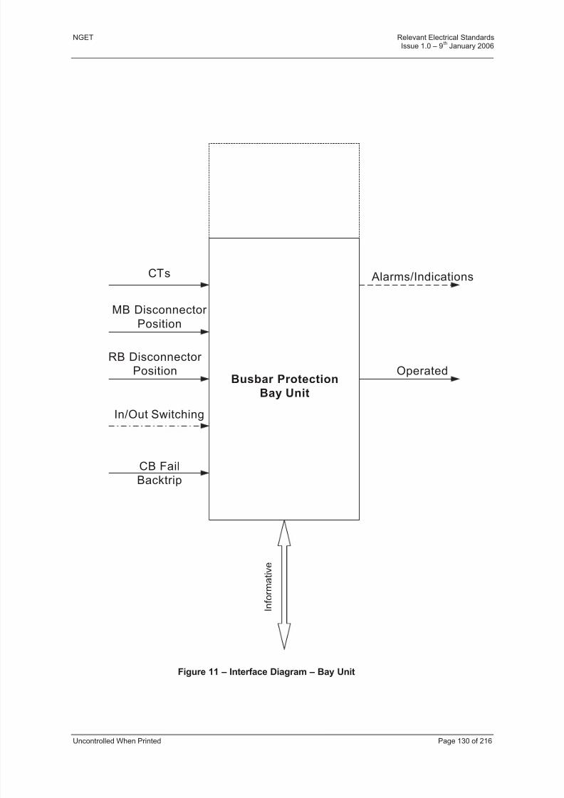
8/3/2019 1 Relevant Standards for Substation Plants
http://slidepdf.com/reader/full/1-relevant-standards-for-substation-plants 137/223
NGET Relevant Electrical StandardsIssue 1.0 – 9
thJanuary 2006
Uncontrolled When Printed Page 130 of 216
Figure 11 – Interface Diagram – Bay Unit
Busbar Protection
Bay Unit
CTs
In/Out Switching
Alarms/Indications
MB Disconnector
Position
RB Disconnector
Position Operated
I n f o r m a t i v e
CB Fail
Backtrip

8/3/2019 1 Relevant Standards for Substation Plants
http://slidepdf.com/reader/full/1-relevant-standards-for-substation-plants 138/223
NGET Relevant Electrical StandardsIssue 1.0 – 9
thJanuary 2006
Uncontrolled When Printed Page 131 of 216
Figure 12 – Interface Diagram – Central Unit
Busbar Protection
Central Unit
I n f o r m a t i v e
Alarms/IndicationsIn/Out Switching

8/3/2019 1 Relevant Standards for Substation Plants
http://slidepdf.com/reader/full/1-relevant-standards-for-substation-plants 139/223
NGET Relevant Electrical StandardsIssue 1.0 – 9
thJanuary 2006
Uncontrolled When Printed Page 132 of 216
18 SECTION 15 - CIRCUIT BREAKER FAIL PROTECTION
18.1 SCOPE
This Section describes the functional and performance requirements and the facilities to be
provided for Circuit Breaker Fail Protection at 400 kV and 275 kV substations.
18.2 REFERENCES
IEC 255-1-00 All-or-nothing Electrical Relays
IEC 255-3 Electrical Relays – Single Input Energising Quantity Measuring Relayswith Dependent or Independent Time
IEC 255-6 Electrical Relays – Measuring Relays and Protection Equipment
IEC 255-22-3 Electrical Relays – Electrical Disturbance Tests for Measuring Relays andProtection Equipment – Radiated Electromagnetic Field Disturbance
Tests
18.3 FUNCTIONAL REQUIREMENTS
18.3.1 General
Circuit breaker fail protection shall cause cessation of fault current within 300 ms of inceptionof the original fault whose detection initiated tripping of the failed circuit breaker.
The functionality shall be implemented in accordance with the Transmission System inEngland and Wales requirements as applied to the site being connected to.
18.3.2 Circuit Breaker Fail Detectors
Circuit breaker fail detector(s) shall be enabled when the protected circuit breaker has been
called upon to trip by operation of its associated protection systems.
The detector(s) shall not operate if the circuit breaker fails to open during a routine switchingoperation or automatic switching sequence unless such failure coincides with or precipitatesthe development of a system fault, resulting in the operation of its associated protectionsystems.
a) A detector shall comprise the following:
(i) A current check element to check if current is still flowing in any phase of thecircuit breaker following circuit breaker trip initiation.
(ii) A timing element to delay tripping until the circuit breaker has had adequatetime for normal extinction of fault current.
The Circuit Breaker Fail system for the substation the User is connecting to will be one of theoptions shown in Figures 15 and 16.
b) For Option A (see Fig. 15):
(i) The current check element shall be enabled by the circuit breaker fail initiatinginputs to monitor the current flowing through the circuit breaker.
(ii) Detection of current in any phase of the circuit breaker above setting shall startand maintain the timing element.
(iii) A trip output from the detector shall be initiated if the current is still abovesetting at the end of the timing period.

8/3/2019 1 Relevant Standards for Substation Plants
http://slidepdf.com/reader/full/1-relevant-standards-for-substation-plants 140/223
NGET Relevant Electrical StandardsIssue 1.0 – 9
thJanuary 2006
Uncontrolled When Printed Page 133 of 216
c) For Option B (see Fig. 16):
(i) The timing element shall be started directly from the circuit breaker fail initiatinginputs.
(ii) The current check element shall be enabled by the timing element at the end of
the timing period and shall monitor the current flowing through the circuitbreaker.
(iii) If the current in any phase of the circuit breaker is above setting, then a tripoutput from the detector shall be initiated.
(iv) For applications using this arrangement, specific measures shall be taken toprevent unwanted back tripping for situations where the circuit breaker hasbeen called upon to close when a trip relay (circuit breaker fail initiating contact)has been operated and not reset.
(v) One such measure would be to block circuit breaker closing for the duration of trip relay operation.
(vi) The method of preventing unwanted back tripping shall be declared by thesupplier.
18.3.3 Current Check Function
The function shall comply with IEC 255-3.
The function shall have, as a minimum requirement, a current setting range of 5% to 25% insteps of 5% or 30% to 100% in steps of 10% depending upon the design of the circuitbreaker.
Informative: The setting range specified is based on the assumption that the rating of the
current check element is 1 A and that the ratio of the current transformer is 2000/1000/1 at 400 kV and 1200/600/1 at 275 kV.
18.3.4 Timing Function
The timing function shall comply with IEC 255-1-00.
The timing function shall have, as a minimum requirement, a time setting range of 50 ms to250 ms in steps of 2 ms.
18.3.5 Circuit Breaker Fail System
Where the circuit breaker fail detector is a software function embedded in a multi-functionnumerical relay, such as busbar protection, one detector shall initiate tripping of contiguouscircuit breakers.
Where the circuit breaker fail detector is effected by discrete conventional relays, twodetectors operating in a two-out-of-two mode shall initiate tripping of contiguous circuitbreakers.
18.3.6 Interfaces
Current transformer inputs of the User’s circuit breaker fail protection shall be capable of operating under the same environmental conditions as NGET’s protection systems at thatsite.
Where the Circuit Breaker Fail Protection is not integrated with the busbar protection, it shallnormally be supplied from a three-phase set of measurement/protection class currenttransformers.
8/3/2019 1 Relevant Standards for Substation Plants
http://slidepdf.com/reader/full/1-relevant-standards-for-substation-plants 141/223
NGET Relevant Electrical StandardsIssue 1.0 – 9
thJanuary 2006
Uncontrolled When Printed Page 134 of 216
The circuit breaker fail protection shall be initiated by a single point digital output from eachof the protection systems that can initiate tripping of the protected circuit breaker.
Informative: The single point digital input is normally a trip relay contact.
Inputs to the Circuit Breaker Fail Protection shall be immune from mal-operation due to
wiring earth faults.
Informative: Double pole switching is one accepted way of ensuring immunity from mal-operation.
18.3.7 Outputs – Busbar Stations
The Circuit Breaker Fail Protection shall initiate back tripping of all other circuit breakersconnected to the same busbar via the tripping system of the busbar protection.
Where the Circuit Breaker Fail Protection is not integrated with the busbar protection, aminimum of two single point outputs shall be provided to initiate backtripping.
The back tripping initiations shall be immune from mal-operation due to wiring earth faults.
Informative: Double pole switching is one accepted way of ensuring immunity from mal-operation.
Where the protection system is associated with a feeder circuit breaker such that tripping of directly connected remote circuit breaker(s) is required, then initiation shall be provided for the DTT and PTT, as provided for the feeder.
A typical tripping logic diagram for a feeder circuit breaker fail protection system at a busbar substation is shown in Figure 17.
18.3.8 Outputs – Mesh Stations
The protection system shall be provided with single point outputs for each mesh corner toinitiate back tripping of all associated local and directly connected remote circuit breakers.
Informative: An accepted way of initiating back tripping is to use the tripping system of bothfirst and second mesh corner protections.
A typical tripping logic diagram for circuit breaker fail protection systems at a meshsubstation is shown in Figure 18.
18.3.9 Alarm Outputs
The following single point outputs shall be provided for the circuit breaker fail protectionsystem alarms as appropriate:
a) Circuit breaker fail protection operated.
b) Protection supply supervision.
c) Protection relay defective.
d) Trip relay operated indication, where a trip relay is provided.
18.4 PERFORMANCE REQUIREMENTS
18.4.1 Current Check Function
The operating time shall be not greater than 10 ms.
The drop off/pick up ratio shall be not less than 70 %.

8/3/2019 1 Relevant Standards for Substation Plants
http://slidepdf.com/reader/full/1-relevant-standards-for-substation-plants 142/223
NGET Relevant Electrical StandardsIssue 1.0 – 9
thJanuary 2006
Uncontrolled When Printed Page 135 of 216
For ‘Option A’ the resetting time shall be not greater than 12 ms for operating currents of up30 times rating (ie 30 A) with a system X/R ratio of 40.
For ‘Option B’ the resetting time shall be not greater than 30 ms.
The error of the function shall be not greater than 5 %.
18.4.2 Timing Function
The reset or disengage time of the function shall be not greater than 30 ms.
For ‘Option A’, only the overshoot of the function shall be not greater than 10 ms.
18.5 TEST REQUIREMENTS
The current check function shall be tested in accordance with the requirements of IEC 255-3to demonstrate that it meets the requirements of 18.4.1.
The timing function shall be tested in accordance with the requirements of IEC 255-1-00 todemonstrate that it meets the requirements of 18.4.2.

8/3/2019 1 Relevant Standards for Substation Plants
http://slidepdf.com/reader/full/1-relevant-standards-for-substation-plants 143/223
NGET Relevant Electrical StandardsIssue 1.0 – 9
thJanuary 2006
Uncontrolled When Printed Page 136 of 216
X103
X105
CB Fail
Detector 1
(See Figs 3A/3B)
CB Fail
Detector 1
(See Figs 3A/3B)
CB Fail
Detector
Busbar Protection
Algorithms
DISCRETE COMPONENT
SCHEME
NUMERICAL BUSBAR
PROTECTION SCHEME
LINE
BUSBAR
NOTE: CT CONNECTIONS SHOWN DEPICT
SIGNALS TO CIRCUIT BREAKER FAIL
PROTECTION ONLY
Figure 13 - Typical CT Arrangement for Circuit Breaker Fail Protection for Busbar Stations - Feeder Circuit
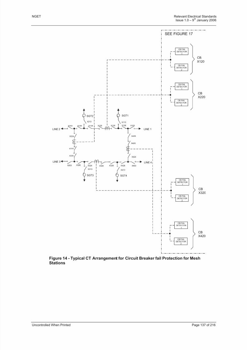
8/3/2019 1 Relevant Standards for Substation Plants
http://slidepdf.com/reader/full/1-relevant-standards-for-substation-plants 144/223
NGET Relevant Electrical StandardsIssue 1.0 – 9
thJanuary 2006
Uncontrolled When Printed Page 137 of 216
X
X
X
X
SGT2 SGT1
SGT3 SGT4
LINE 1
LINE 4LINE 3
LINE 2
X203
X224
X220
X226 X128
X213
X220
X203 X326 X328
X313
X320 X426
X413
X403X324
X424
X420
X428
X103
X113
X120 X126X128
CB FAIL
DETECTOR1
CB FAIL
DETECTOR2
CB FAILDETECTOR
1
CB FAILDETECTOR
2
CB FAILDETECTOR1
CB FAIL
DETECTOR2
CB FAILDETECTOR
1
CB FAIL
DETECTOR2
CB
X420
CB
X320
CB
X220
CB
X120
SEE FIGURE 17
Figure 14 - Typical CT Arrangement for Circuit Breaker fail Protection for MeshStations
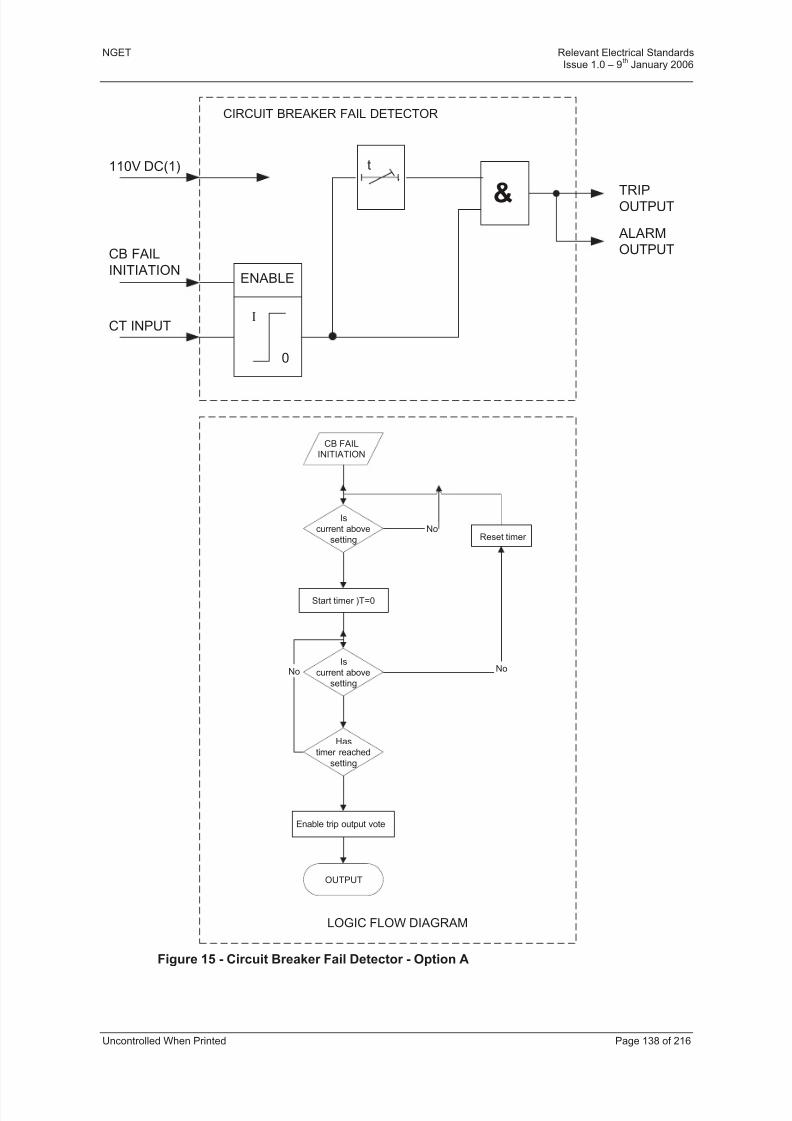
8/3/2019 1 Relevant Standards for Substation Plants
http://slidepdf.com/reader/full/1-relevant-standards-for-substation-plants 145/223
NGET Relevant Electrical StandardsIssue 1.0 – 9
thJanuary 2006
Uncontrolled When Printed Page 138 of 216
I
0
ENABLE
t
& TRIPOUTPUT
ALARM
OUTPUT
CIRCUIT BREAKER FAIL DETECTOR
110V DC(1)
CB FAIL
INITIATION
CT INPUT
LOGIC FLOW DIAGRAM
No No
No
CB FAILINITIATION
Is
current above
setting
Start timer )T=0
Is
current above
setting
Has
timer reached
setting
Enable trip output vote
OUTPUT
Reset timer
Figure 15 - Circuit Breaker Fail Detector - Option A
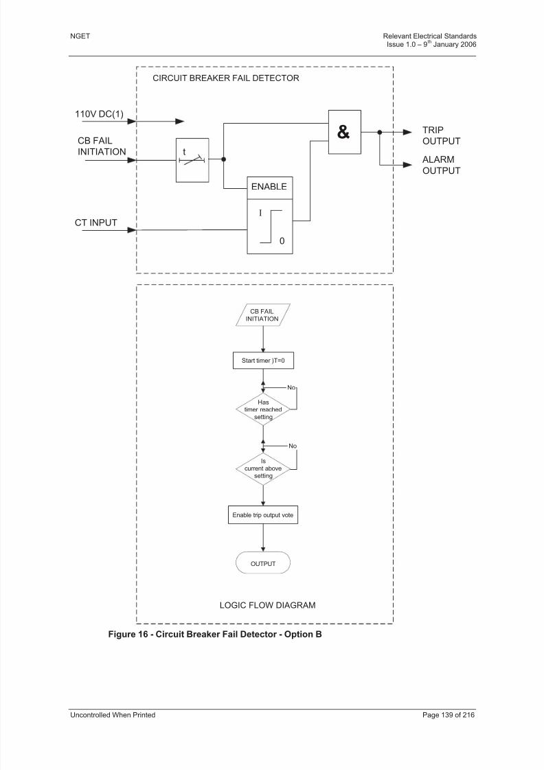
8/3/2019 1 Relevant Standards for Substation Plants
http://slidepdf.com/reader/full/1-relevant-standards-for-substation-plants 146/223
NGET Relevant Electrical StandardsIssue 1.0 – 9
thJanuary 2006
Uncontrolled When Printed Page 139 of 216
& TRIPOUTPUT
ALARM
OUTPUT
CIRCUIT BREAKER FAIL DETECTOR
110V DC(1)
CB FAIL
INITIATION
CT INPUT
LOGIC FLOW DIAGRAM
I
0
ENABLE
t
No
CB FAIL
INITIATION
Start timer )T=0
Is
current abovesetting
Hastimer reached
setting
Enable trip output vote
OUTPUT
No
Figure 16 - Circuit Breaker Fail Detector - Option B

8/3/2019 1 Relevant Standards for Substation Plants
http://slidepdf.com/reader/full/1-relevant-standards-for-substation-plants 147/223
NGET Relevant Electrical StandardsIssue 1.0 – 9
thJanuary 2006
Uncontrolled When Printed Page 140 of 216
CB FAIL
DETECTORCB FAIL
INITIATION
BACKTRIP
INITIATION
&
S
R
X
X
INTERTRIP
INTERTRIP
EVENT LOG/
INDICATION
START TRIP
RELAY RESET
TRIP RELAY
RESET
PROTECTION
OPERATED
EVENTS/ALARMS
NUMERICAL BUSBAR PROTECTION SCHEME
BUSBAR/
BACKTRIP
110V DC(1)
NOTE:- X ISOLATABLE SIGNAL
Figure 17 - Typical Tripping Logic Diagram for Circuit Breaker Fail Protection Systemfor Busbar Substations - Feeder Circuit
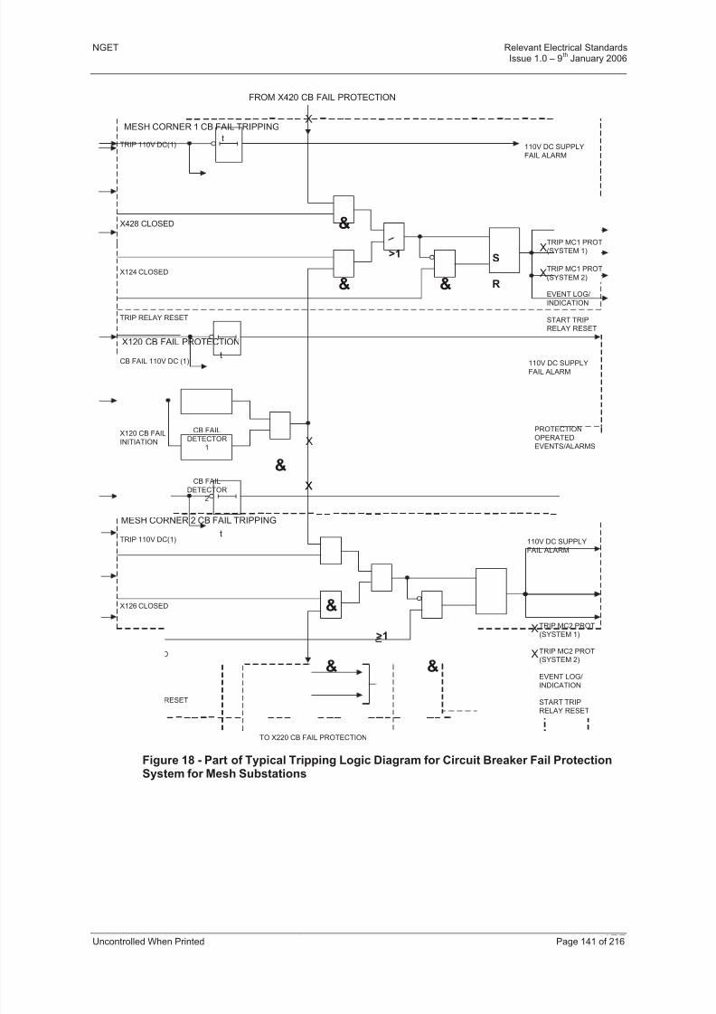
8/3/2019 1 Relevant Standards for Substation Plants
http://slidepdf.com/reader/full/1-relevant-standards-for-substation-plants 148/223
NGET Relevant Electrical StandardsIssue 1.0 – 9
thJanuary 2006
Uncontrolled When Printed Page 141 of 216
S
R
t
CB FAIL
DETECTOR
1
CB FAIL
DETECTOR
2
&
X
X
&
&
>1
&
X
X
t
&
&
>1
&
S
R
XX
t
110V DC SUPPLY
FAIL ALARM
110V DC SUPPLY
FAIL ALARM
110V DC SUPPLY
FAIL ALARM
FROM X420 CB FAIL PROTECTION
MESH CORNER 1 CB FAIL TRIPPING
X120 CB FAIL PROTECTION
MESH CORNER 2 CB FAIL TRIPPING
TO X220 CB FAIL PROTECTION
X126 CLOSED
X224 CLOSED
X428 CLOSED
X124 CLOSED
TRIP RELAY RESET
TRIP 110V DC(1)
TRIP RELAY RESET
CB FAIL 110V DC (1)
TRIP 110V DC(1)
X
X
START TRIP
RELAY RESET
EVENT LOG/
INDICATION
TRIP MC2 PROT
(SYSTEM 1)
TRIP MC2 PROT
(SYSTEM 2)
TRIP MC1 PROT
(SYSTEM 1)
TRIP MC1 PROT
(SYSTEM 2)
EVENT LOG/
INDICATION
START TRIP
RELAY RESET
PROTECTION
OPERATED
EVENTS/ALARMS
X120 CB FAIL
INITIATION
Figure 18 - Part of Typical Tripping Logic Diagram for Circuit Breaker Fail ProtectionSystem for Mesh Substations

8/3/2019 1 Relevant Standards for Substation Plants
http://slidepdf.com/reader/full/1-relevant-standards-for-substation-plants 149/223
NGET Relevant Electrical StandardsIssue 1.0 – 9
thJanuary 2006
Uncontrolled When Printed Page 142 of 216
19 SECTION 16 - ENVIRONMENTAL AND TEST REQUIREMENTS FOR ELECTRONICEQUIPMENT
19.1 SCOPE
All electronic equipment supplied for operational use within NGET’s substation busbar protection zone of the User connection to NGET’s electricity transmission network must meetthe required functionality and performance as set out in NGET Required Electric Standards.These requirements must be met under the relevant environmental conditions stated in thisSection.
19.2 INTRODUCTION
19.2.1 Relationship with European Standards
Informative: This Section generally references functional requirements and tests described inIEC or BS Standards. However, in some cases there are no standards that adequately cover the unique performance and functional requirements of an electricity supply system.In these instances specific requirements and tests are detailed in this document.
CENELEC document Electronic Equipment for use in Power Installations (EN 50178) givesminimum design and manufacture requirements with which control equipment within thescope of this specification must comply.
This Section specifies those performance requirements that must be met by electronicequipment to be used in NGET transmission locations.
19.2.2 Guidance to Users
This Section is a generic requirement and therefore when used to specify requirements for equipment to be purchased, this Section must be supplemented by specific requirementsrelating to the equipment and application concerned. In most cases this will take the form,inter alia, of specifying which optional tests are to be applied and the test levels required for
each port. This information will be contained in the corresponding functional specification or the contract documentation as appropriate.
19.3 DEFINITIONS
EUT Equipment under test.
Port A particular interface of the specified equipment with the externalelectromagnetic environment (see Figure 19). For interferenceimmunity tests, the level of test to be applied is specified on a portby port basis.
Enclosure Port The physical boundary of the equipment which electromagnetic
fields may radiate through or impinge on.
19.4 REFERENCES
This Section makes reference to the following related specifications:
ISO 10012-1 Quality Assurance Requirements for measuring equipment.(BS EN 30012-1)
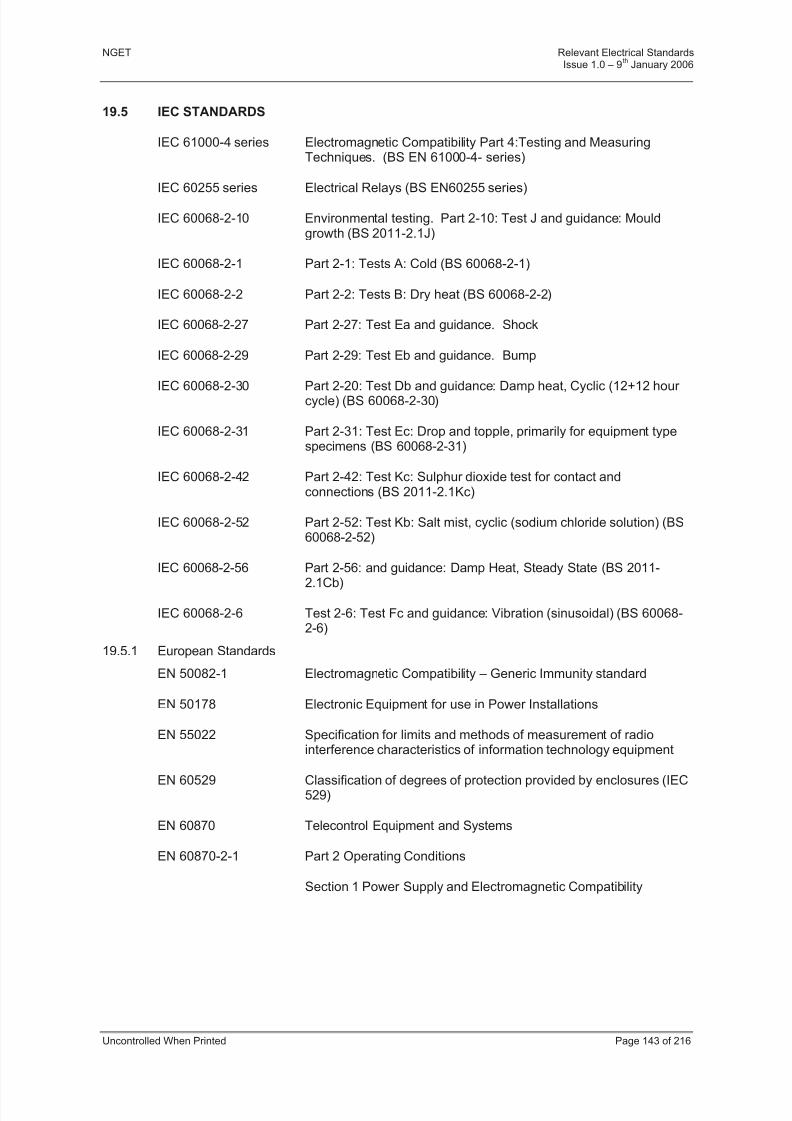
8/3/2019 1 Relevant Standards for Substation Plants
http://slidepdf.com/reader/full/1-relevant-standards-for-substation-plants 150/223
NGET Relevant Electrical StandardsIssue 1.0 – 9
thJanuary 2006
Uncontrolled When Printed Page 143 of 216
19.5 IEC STANDARDS
IEC 61000-4 series Electromagnetic Compatibility Part 4:Testing and MeasuringTechniques. (BS EN 61000-4- series)
IEC 60255 series Electrical Relays (BS EN60255 series)
IEC 60068-2-10 Environmental testing. Part 2-10: Test J and guidance: Mouldgrowth (BS 2011-2.1J)
IEC 60068-2-1 Part 2-1: Tests A: Cold (BS 60068-2-1)
IEC 60068-2-2 Part 2-2: Tests B: Dry heat (BS 60068-2-2)
IEC 60068-2-27 Part 2-27: Test Ea and guidance. Shock
IEC 60068-2-29 Part 2-29: Test Eb and guidance. Bump
IEC 60068-2-30 Part 2-20: Test Db and guidance: Damp heat, Cyclic (12+12 hour cycle) (BS 60068-2-30)
IEC 60068-2-31 Part 2-31: Test Ec: Drop and topple, primarily for equipment typespecimens (BS 60068-2-31)
IEC 60068-2-42 Part 2-42: Test Kc: Sulphur dioxide test for contact andconnections (BS 2011-2.1Kc)
IEC 60068-2-52 Part 2-52: Test Kb: Salt mist, cyclic (sodium chloride solution) (BS60068-2-52)
IEC 60068-2-56 Part 2-56: and guidance: Damp Heat, Steady State (BS 2011-
2.1Cb)
IEC 60068-2-6 Test 2-6: Test Fc and guidance: Vibration (sinusoidal) (BS 60068-2-6)
19.5.1 European Standards
EN 50082-1 Electromagnetic Compatibility – Generic Immunity standard
EN 50178 Electronic Equipment for use in Power Installations
EN 55022 Specification for limits and methods of measurement of radiointerference characteristics of information technology equipment
EN 60529 Classification of degrees of protection provided by enclosures (IEC529)
EN 60870 Telecontrol Equipment and Systems
EN 60870-2-1 Part 2 Operating Conditions
Section 1 Power Supply and Electromagnetic Compatibility

8/3/2019 1 Relevant Standards for Substation Plants
http://slidepdf.com/reader/full/1-relevant-standards-for-substation-plants 151/223
NGET Relevant Electrical StandardsIssue 1.0 – 9
thJanuary 2006
Uncontrolled When Printed Page 144 of 216
ETS 300 132-2 European Telecommunications Standards Institute: EquipmentEngineering; Power supply interface at the input totelecommunications equipment; Part 2: Operated by direct current(dc)
ETS 300 386-1 European Telecommunications Standards Institute: EquipmentEngineering; Public Telecommunications network equipmentElectromagnetic compatibility requirements; Part 1: Product familyoverview, compliance criteria and test levels
19.6 GENERAL REQUIREMENTS
Informative: Electronic equipment for operational use within NGET is required to comply withspecific environmental performance criteria. This Section sets out the essence of thesecriteria, with particular emphasis on the testing required. Clause 19.6 General Requirementsstates these criteria. Clauses 19.7, 19.8, 19.9 and 19.10 Test Requirements, define thetests required to prove that these requirements have been met under various ranges of environmental conditions.
19.6.1 Environment
The equipment shall be subjected to environmental factors such as electrical interference,supply voltage variations, nuclear radiation, dust, vibration, temperature, and salt mist.Where special equipment enclosures are required to satisfy these requirements, the supplier shall define its Degree of Protection by stating its IP Code as given in EN 60529 (IEC 529).
The following clauses define the conditions that the equipment needs to withstand withouteither the performance being degraded or the life being shortened.
19.6.2 Temperature and Humidity
Equipment shall operate within its functional specification over the range of the specifiedatmospheric environmental classes, as defined in the Part 4, Section 1 - Table 1,
Temperature and Humidity Environmental Classes.
Where any Class 1 or Class 2 item of equipment is to be mounted within an enclosurehousing other items of equipment, it shall be capable of normal operation at a temperature
15 C higher than the upper temperature limit of the environmental class.
The temperature rise above ambient within an enclosure, when the equipment is operating
normally, shall not exceed 10 C.
Equipment which can directly cause the operation of a circuit breaker shall operate within itsfunctional specification over the Class 3 range of the atmospheric environmental classes, asdefined in the Part 4, Section 1 - Table 1, Temperature and Humidity Environmental Classes.
The additional 15 C enclosure factor need not apply.
19.6.3 Mechanical19.6.4 Shock and Vibration
Performance life shall not be affected by the Drop and Topple Test, where specified.
Where specified, equipment shall conform to the requirements of the Vibration Test.
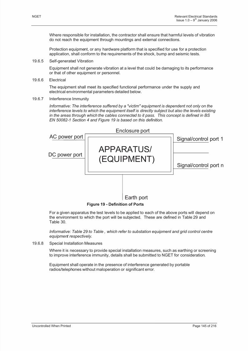
8/3/2019 1 Relevant Standards for Substation Plants
http://slidepdf.com/reader/full/1-relevant-standards-for-substation-plants 152/223
NGET Relevant Electrical StandardsIssue 1.0 – 9
thJanuary 2006
Uncontrolled When Printed Page 145 of 216
Where responsible for installation, the contractor shall ensure that harmful levels of vibrationdo not reach the equipment through mountings and external connections.
Protection equipment, or any hardware platform that is specified for use for a protectionapplication, shall conform to the requirements of the shock, bump and seismic tests.
19.6.5 Self-generated Vibration
Equipment shall not generate vibration at a level that could be damaging to its performanceor that of other equipment or personnel.
19.6.6 Electrical
The equipment shall meet its specified functional performance under the supply andelectrical environmental parameters detailed below.
19.6.7 Interference Immunity
Informative: The interference suffered by a "victim" equipment is dependent not only on theinterference levels to which the equipment itself is directly subject but also the levels existing in the areas through which the cables connected to it pass. This concept is defined in BS
EN 50082-1 Section 4 and Figure 19 is based on this definition.
Figure 19 - Definition of Ports
For a given apparatus the test levels to be applied to each of the above ports will depend onthe environment to which the port will be subjected. These are defined in Table 29 andTable 30.
Informative: Table 29 to Table , which refer to substation equipment and grid control centreequipment respectively.
19.6.8 Special Installation Measures
Where it is necessary to provide special installation measures, such as earthing or screeningto improve interference immunity, details shall be submitted to NGET for consideration.
Equipment shall operate in the presence of interference generated by portableradios/telephones without maloperation or significant error.
APPARATUS/(EQUIPMENT)
AC power port
DC power port
Signal/control port 1
Signal/control port n
Earth port
Enclosure port
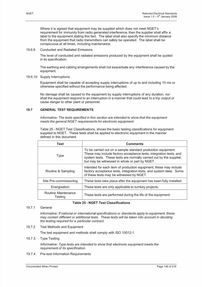
8/3/2019 1 Relevant Standards for Substation Plants
http://slidepdf.com/reader/full/1-relevant-standards-for-substation-plants 153/223
8/3/2019 1 Relevant Standards for Substation Plants
http://slidepdf.com/reader/full/1-relevant-standards-for-substation-plants 154/223
NGET Relevant Electrical StandardsIssue 1.0 – 9
thJanuary 2006
Uncontrolled When Printed Page 147 of 216
A complete and detailed schedule of the proposed tests shall be submitted by the contractor and agreed by NGET in reasonable time prior to their commencement.
19.7.5 Test Schedule
The following information shall be included in the test schedule:
a) A detailed timetable including time and place for all tests.
b) An itemised list of the test equipment to be used, with full performance specificationand calibration details.
c) Specific details of the equipment to be tested including a block diagram showing allthe ports of the equipment, specification, serial numbers etc.
d) A clear description of the arrangement for each test as applied to the specificequipment, including details of the test methods interconnection diagrams, grouping of i/o (where appropriate), measurements, observations required and Pass/Fail Criteria.
e) The forms on which the test results are to be recorded (see below).
f) A document setting out the procedures to be adopted if the tested item fails to meet itsspecification.
19.7.6 Test Result Forms
The test result forms shall include the following:
a) Contract reference.
b) Place, time and date of each test.
c) Type and serial numbers of equipment to be tested.
d) Diagram of the intended and actual test configurations.
e) Environmental conditions intended and existing at the time of the test.
f) Name, status, department and company of test engineer and test observers.
g) Parameters to be measured or observed and each measured or observed result.
h) Signature of test engineer and test observers.
i) Statement of whether the equipment has passed or failed the test, and reasons for failure if necessary.
j) Action taken as a result of a test failure.
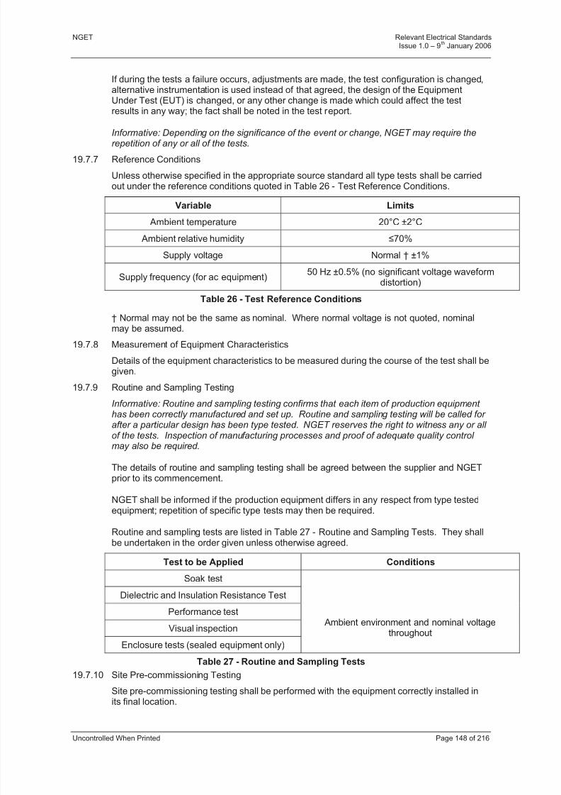
8/3/2019 1 Relevant Standards for Substation Plants
http://slidepdf.com/reader/full/1-relevant-standards-for-substation-plants 155/223
NGET Relevant Electrical StandardsIssue 1.0 – 9
thJanuary 2006
Uncontrolled When Printed Page 148 of 216
If during the tests a failure occurs, adjustments are made, the test configuration is changed,alternative instrumentation is used instead of that agreed, the design of the EquipmentUnder Test (EUT) is changed, or any other change is made which could affect the testresults in any way; the fact shall be noted in the test report.
Informative: Depending on the significance of the event or change, NGET may require therepetition of any or all of the tests.
19.7.7 Reference Conditions
Unless otherwise specified in the appropriate source standard all type tests shall be carriedout under the reference conditions quoted in Table 26 - Test Reference Conditions.
Variable Limits
Ambient temperature 20°C ±2°C
Ambient relative humidity 70%
Supply voltage Normal † ±1%
Supply frequency (for ac equipment) 50 Hz ±0.5% (no significant voltage waveformdistortion)
Table 26 - Test Reference Conditions
† Normal may not be the same as nominal. Where normal voltage is not quoted, nominalmay be assumed.
19.7.8 Measurement of Equipment Characteristics
Details of the equipment characteristics to be measured during the course of the test shall begiven.
19.7.9 Routine and Sampling Testing
Informative: Routine and sampling testing confirms that each item of production equipment has been correctly manufactured and set up. Routine and sampling testing will be called for after a particular design has been type tested. NGET reserves the right to witness any or all of the tests. Inspection of manufacturing processes and proof of adequate quality control may also be required.
The details of routine and sampling testing shall be agreed between the supplier and NGETprior to its commencement.
NGET shall be informed if the production equipment differs in any respect from type testedequipment; repetition of specific type tests may then be required.
Routine and sampling tests are listed in Table 27 - Routine and Sampling Tests. They shall
be undertaken in the order given unless otherwise agreed.
Test to be Applied Conditions
Soak test
Dielectric and Insulation Resistance Test
Performance test
Visual inspection
Enclosure tests (sealed equipment only)
Ambient environment and nominal voltagethroughout
Table 27 - Routine and Sampling Tests
19.7.10 Site Pre-commissioning Testing
Site pre-commissioning testing shall be performed with the equipment correctly installed inits final location.

8/3/2019 1 Relevant Standards for Substation Plants
http://slidepdf.com/reader/full/1-relevant-standards-for-substation-plants 156/223
NGET Relevant Electrical StandardsIssue 1.0 – 9
thJanuary 2006
Uncontrolled When Printed Page 149 of 216
Details of tests shall be agreed between the supplier and NGET.
The tests shall demonstrate that:
a) No damage to the equipment has occurred in transit and that it has been properlyinstalled.
b) The equipment is suitable for and functions correctly in its environment.
c) The immunity to electromagnetic interference on site is satisfactory so that theequipment performs to its specification under site conditions.
d) The equipment is correctly earthed.
e) The equipment is capable of performing its specified function when connected to other equipment.
f) The equipment has sufficient range in its variable and interrelated controls.
Site pre-commissioning testing shall include tests from Table 28 - Site Pre-commissioningTests.
The tests shall include a 72 hour unbroken operational run, after which a performance checkshall be carried out.
Test to be Applied Comment
Visual inspection When finally installed
Performance tests At actual site voltage
Supply variation and interruption tests† With site supplies
Supply changeover tests† With site suppliesElectrical noise tests† With site supplies
Soak test With site supplies
Table 28 - Site Pre-commissioning Tests
† Where site conditions allow.
19.7.11 Description of the Tests Required
Informative: The following clauses give general details of the tests discussed in Clauses:Type Testing, Routine and Sampling Testing, Site Pre-commissioning Testing.
Informative: Particulars of the performance requirements and pass/fail criteria will beincluded in the individual equipment specification.

8/3/2019 1 Relevant Standards for Substation Plants
http://slidepdf.com/reader/full/1-relevant-standards-for-substation-plants 157/223
NGET Relevant Electrical StandardsIssue 1.0 – 9
thJanuary 2006
Uncontrolled When Printed Page 150 of 216
19.7.12 Non Maloperation Tests
For Non Maloperation tests the Equipment Under Test (EUT) is required to perform to itsspecification in all respects while being subjected to the test conditions.
Informative: For some equipment which is not concerned with Control, Protection and other
continuous service facilities, it may not be necessary that error free operation continuesduring primary plant operations.
Equipment for which error-free operation during primary plant operations is not a mandatoryrequirement shall be identified in the contract documentation (Type Registered List). For thisequipment errors will be permitted during tests, however damage must not result and theEUT must revert automatically to error-free operation within 30 seconds of terminating thetest without operator intervention.
19.7.13 Protection Equipment
Informative: The IEC 60255 series of Standards are the product specific standards for protection equipment. As such they often contain reference conditions and acceptancecriteria specifically designed for protection. Generally the tests and test levels specified in
Table 29 are compatible with the IEC 60255 tests. For each test in this specification theappropriate IEC 60255 standard, where it exists, will be indicated.
In the case of protection equipment or any hardware platform that is specified for use for aprotection application, the method of application and acceptance criteria for the tests asdefined in the appropriate IEC 60255 standard is definitive and shall take precedence.
In the case of protection equipment or any hardware platform that is specified for use for aprotection application, the test levels required are stated in Table 29 and Table 30.
19.7.14 Substation Control Equipment
Informative: Substation Control Equipment comes within the scope of the BS EN 60870 series of standards. Specifically BS EN 60870-2-1 covers the power supply and
electromagnetic compatibility requirements and BS EN 60870-2-2 defines the environmental requirements. They have been adopted by Cenelec as product family standards for thisequipment. Table 29 relates the test levels called up by this Section with those required by BS EN 60870.
19.7.15 Visual Inspections
a) Initial Visual Inspection (Type Test)
The initial visual inspection shall be carried out to ensure that the equipment is of sound construction and appears to satisfy the specified requirements. Features thatcan be checked at this stage include labelling, maintenance accessibility, safety,correct supply voltages and output ranges.
b) Interim Visual Inspection (Type Test)
Interim visual inspections are carried out during the testing schedule to check thatequipment has survived a particular test.
c) Final Visual Inspection (Type Test)
At the end of the test schedule a final visual inspection is required to check whether the test programme has harmed the equipment. Signs of component overheating,loosening of fasteners, damage to insulation and similar effects shall be noted.
d) Visual Inspection (Routine and Sampling Test)
8/3/2019 1 Relevant Standards for Substation Plants
http://slidepdf.com/reader/full/1-relevant-standards-for-substation-plants 158/223
8/3/2019 1 Relevant Standards for Substation Plants
http://slidepdf.com/reader/full/1-relevant-standards-for-substation-plants 159/223
NGET Relevant Electrical StandardsIssue 1.0 – 9
thJanuary 2006
Uncontrolled When Printed Page 152 of 216
e) Performance Test (Site Pre-commissioning Test)
The site performance test shall take place with the equipment fully installed andpowered from site supplies. Associated plant and equipment must have undergoneseparate tests before the final site performance test takes place.
19.8 ELECTRICAL ENVIRONMENTAL TESTS
Informative: The tests to be applied are summarised in Table 29 and Table 30, substationequipment and Table , control centre equipment. They are required to establish that theequipment will perform in accordance with its specification in its working environment. Thetables specify the levels of the tests to be applied to specific ports of the equipment. The port connections are more fully defined in Table 32 not all the tests will be appropriate toevery item of equipment.
Informative: The tests in Table 29 are mandatory while those in Table 30 need only be called up if it is a specific requirement of the contract. However, it should be noted that certain of these tests are required in order to comply with BS EN 60870-2-1 (see Section on
Substation Control Equipment). The test descriptions specify whether the equipment isrequired to function correctly during the test (non-maloperate) or whether the equipment isrequired to resist the specified test conditions without damage (withstand).
Unless otherwise stated in the appropriate Section for the EUT, equipment, when subjectedto the non-maloperate tests, shall perform to specification during and after application of thetests. See also Section on Non Maloperation Tests.
Except where otherwise stated, the method of application for each test shall be as specifiedin the appropriate source standard as quoted in Table 29, Table 30 and Table 31.
The interference tests are designed to demonstrate that equipment is likely to be compatiblewith its environment. If specific measures on site are required to achieve the desired degree
of immunity, full details of these measures shall be submitted to NGET for assessment.
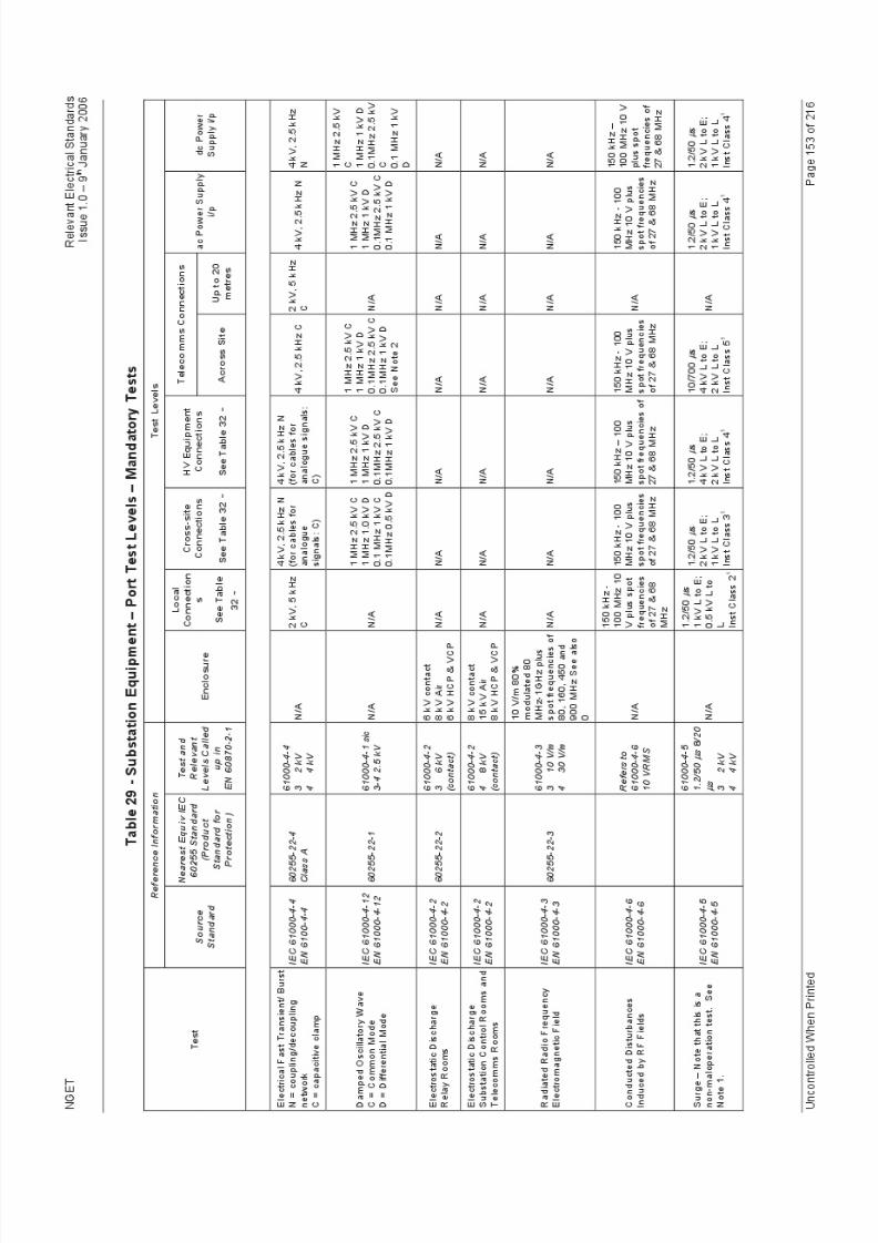
8/3/2019 1 Relevant Standards for Substation Plants
http://slidepdf.com/reader/full/1-relevant-standards-for-substation-plants 160/223
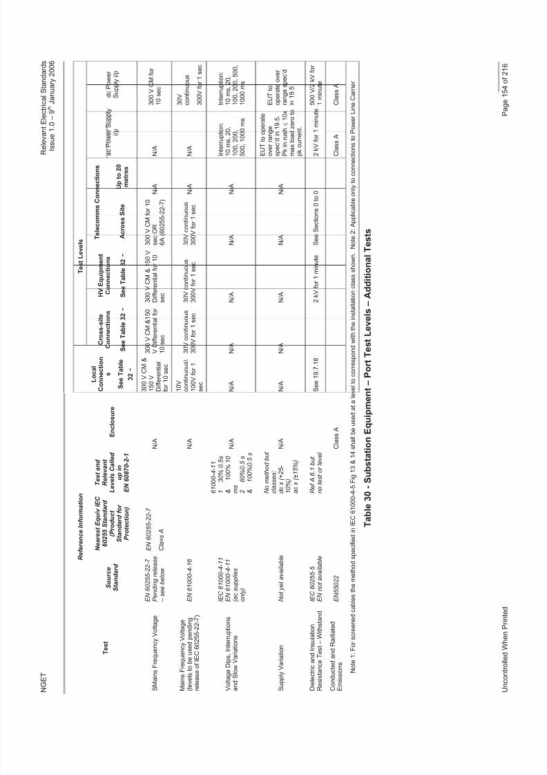
8/3/2019 1 Relevant Standards for Substation Plants
http://slidepdf.com/reader/full/1-relevant-standards-for-substation-plants 161/223
N G E T
R e l e v a n t E l e c t r i c a l S t a n d a r d s
I s s u e 1 . 0 – 9 t h J a n u a r y 2 0 0 6
U n c o n t r o
l l e d W h e n P r i n t e d
P a g e 1 5 4 o f 2 1 6
R e f e r e n c e
I n f o r m a t i o n
T e s t L e v e l s
T e l e c o m m s C o n n e c t i o n s
T e s t
S o u r c e
S t a n d a r d
N e a r e s
t E q u i v I E C
6 0 2 5 5 S t a n d a r d
( P
r o d u c t
S t a n d a r d f o r
P r o
t e c t i o n )
T e s t a n d
R e l e v a n t
L e v e l s C a l l e d
u p i n
E N 6 0 8 7 0 - 2 - 1
E n c l o s u r e
L o c a l
C o n n e c t i o n
s
S e e T a b l e
3 2 -
C r o s s - s i t e
C o n n e c t i o n s
S e e T a b l e 3 2 -
H V E q u i p m
e n t
C o n n e c t i o
n s
S e e T a b l e 3 2 -
A c r o s s S i t e
U p t o 2 0
m e t r e s
a c P o w e r S u p p l y
i / p
d c P o w e r
S u p p l y i / p
S M a i n s F
r e q u e n c y V o l t a g e
E N 6 0 2 5 5 - 2 2 - 7
P e n d i n g r e l e a s e
– s e e b e l o w
E N 6 0 2
5 5 - 2 2 - 7
C l a s s A
N / A
3 0 0 V C M &
1 5 0 V
D i f f e r e n t i a l
f o r 1 0 s e c
3 0 0 V C M & 1 5 0
V D i f f e r e n t i a l f o r
1 0 s e c
3 0 0 V C M & 1
5 0 V
D i f f e r e n t i a l f o r 1 0
s e c
3 0 0 V C M f o r 1 0
s e c O R
6 A ( 6 0 2 5 5 - 2 2 - 7 )
N / A
N / A
3 0 0 V C M f o r
1 0 s e c
M a i n s F r e q u e n c y V o l t a g e
( l e v e l s t o
b e u s e d p e n d i n g
r e l e a s e o
f I E C 6 0 2 5 5 - 2 2 - 7 )
E N 6 1 0 0 0 - 4 - 1 6
N / A
1 0 V
c o n t i n u o u s \
1 0 0 V f o r 1
s e c
3 0 V c o n t i n u o u s
3 0 0 V f o r 1 s e c
3 0 V c o n t i n u o u s
3 0 0 V f o r 1 s e c
3 0 V c o n t i n u o u s
3 0 0 V f o r 1 s e c
N / A
N / A
3 0 V
c o n t i n u o u s
3 0 0 V f o r 1 s e c
V o l t a g e D
i p s , I n t e r r u p t i o n s
a n d S l o w
V a r i a t i o n s
I E C 6 1 0 0 0 - 4 - 1 1
E N 6 1 0 0 0 - 4 - 1 1
( a c s u p p l i e s
o n l y )
6 1 0 0 0 - 4 - 1 1
1
3 0 % 0 . 5 s
&
1 0 0 % 1
0
m s 2
6 0 % 0 . 5 s
&
1 0 0 % 0 . 5 s
N / A
N / A
N / A
N / A
N / A
N / A
I n t e r r u p t i o n :
1 0 m s , 2 0 ,
1 0 0 , 2 0 0 ,
5 0 0 , 1 0 0 0 m s
I n t e r r u p t i o n :
1 0 m s , 2 0 ,
1 0 0 , 2 0 0 , 5 0 0 ,
1 0 0 0 m s
S u p p l y V a r i a t i o n
N o t y e t a v a i l a b l e
N o m e t h o d b u t
c l a s s e s :
d c x ( + 2 5 -
1 0 % )
a c x ( ± 1 5 % )
N / A
N / A
N / A
N / A
N / A
N / A
E U T t o o
p e r a t e
o v e r r a n g
e
s p e c ’ d i n
1 9 . 5 .
P k i n - r u s h 1
0 x
m a x l o a d
z e r o t o
p k c u r r e n
t .
E U T t o
o p e r a t e o v e r
r a n g e s p e c ’ d
i n 1 9 . 5
D i e l e c t r i c
a n d I n s u l a t i o n
R e s i s t a n c e T e s t – W i t h s t a n d
I E C 6 0 2 5 5 - 5
E N n o t a v a i l a b l e
R e f A . 6 . 1 b u t
n o t e s t o r l e v e l
S e e 1 9 . 7 . 1 8
2 k V f o r 1 m i n
u t e
S e e S e c t i o n s 0 t o 0
2 k V f o r 1 m i n u t e 5 0 0 V / 2 k V f o r
1 m i n u t e
C o n d u c t e
d a n d R a d i a t e d
E m i s s i o n s
E N 5 5 0 2 2
C l a s s A
C l a s s A
C l a s s A
N o
t e 1 : F o r s c r e e n e d c a b l e s t h e m e t h o d s p e c i f i e d i n I E C 6 1 0 0 0 - 4 - 5 F i g 1 3 & 1 4 s h a l l b e u s e d a t a l e v e l t o c o r r e s p o n d w i t h t h e i n s t a l l a t i o n c l a s s s h o w n . N o t e 2 : A p p l i c a b l e o n l y t o c o n n e c t i o n s t o P
o w e r L i n e C a r r i e r
T a b l e 3 0 - S u b s t a t i o n E q u i p m e
n t – P o r t T e s t L e v e l s – A d d i t i o n
a l T e s t s
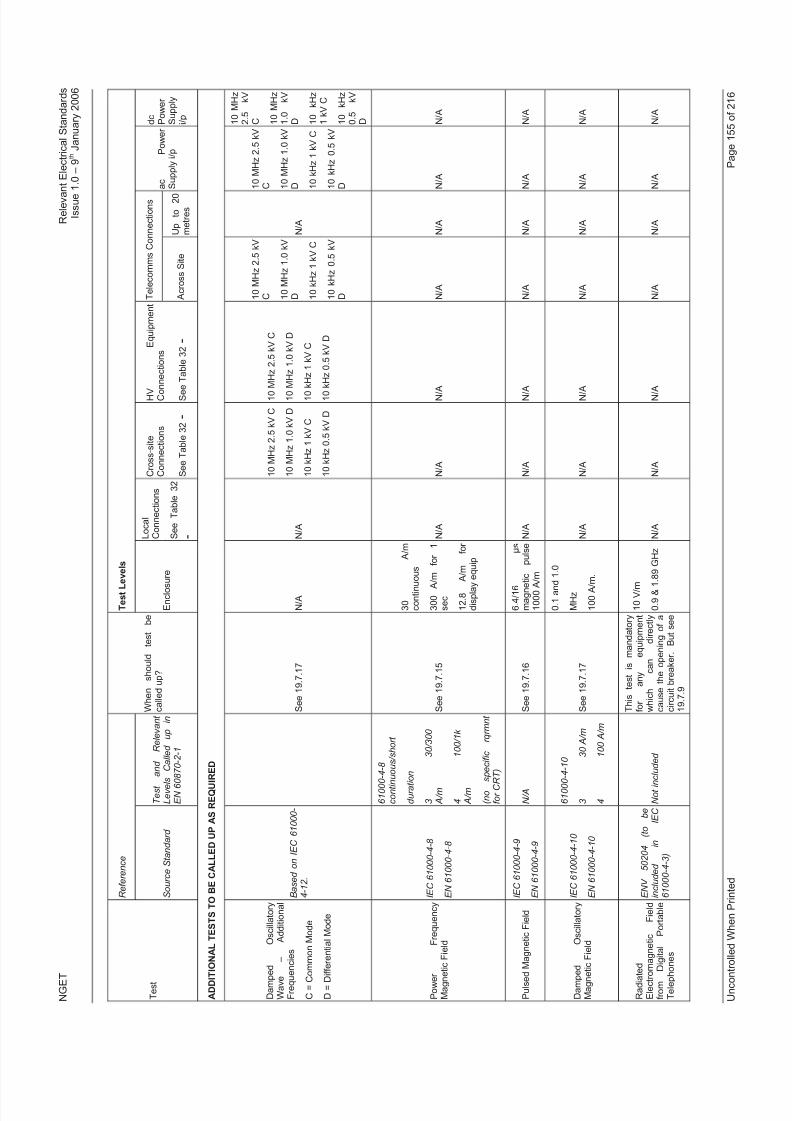
8/3/2019 1 Relevant Standards for Substation Plants
http://slidepdf.com/reader/full/1-relevant-standards-for-substation-plants 162/223

8/3/2019 1 Relevant Standards for Substation Plants
http://slidepdf.com/reader/full/1-relevant-standards-for-substation-plants 163/223
N G E T
R e l e v a n t E l e c t r i c a l S t a n d a r d s
I s s u e 1 . 0 – 9 t h J a n u a r y 2 0 0 6
U n c o n t r o
l l e d W h e n P r i n t e d
P a g e 1 5 6 o f 2 1 6
V o l t a g e
D i p s ,
I n t e r r u p t i o n s a n d S l o w
V a r i a t i o n s
I E C 6 1 0 0 0 - 4 - 1 1
E N 6 1 0 0 0 - 4 - 1 1
6 1 0 0 0 - 4 - 1 1
1
3 0 %
&
1 0 0 %
1 0 m s
2
6 0 %
&
1 0 0 %
. 5 s
S e e 1 9 . 7 . 4
N / A
N / A
N / A
N / A
N / A
N / A
D i p s :
3 0 % : 1 0 m s &
2 0 m s
6 0 % : 1 0 , 5 0 ,
1 0 0 , 2 5 0 , 5 0 0
& 1 0 0 0 m s
N / A
V o l t a g e
D i p s ,
I n t e r r u p t i o n s a n d S l o w
V a r i a t i o n s
I E C 6 1 0 0 0 - 4 - 1 1
E N 6 1 0 0 0 - 4 - 1 1
6 1 0 0 0 - 4 - 1 1
F a s t v a r i a t i o n
1
U
=
±
8 %
2
U
=
±
1 2 %
T h i s t e s t i s m a n d a t o r y
f o r
a n y
e q u i p m e n t
w h i c h i s i n t e n d e d f o r a
p r o t e c t i o n a p p l i c a t i o n
N / A
N / A
N / A
N / A
N / A
N / A
N / A
R a m p i n
g
f r o m
0 %
t o
1 0 0 % &
1 0 0 %
t o
0 %
o v e r
1
m i n u t e
C o n d u c t e
d
D i s t u r b a n
c e s 1 5 H z t o
1 5 0 k H z
I E C 6 1 0 0 0 - 4 - 1 6
E N 6 1 0 0 0 - 4 - 1 6
N o t i n c l u
d e d
S e e 1 9 . 7 . 1 2
N / A
1 0 - 1 - 1 - 1 0 V
1 0 - 1 - 1 - 1 0 V
1 0 - 1
- 1 - 1 0 V
1 0 - 1 - 1 - 1 0 V
1 0 - 1 - 1 - 1 0
V
1 0 - 1 - 1 - 1 0 V
1 0 - 1 - 1 -
1 0 V
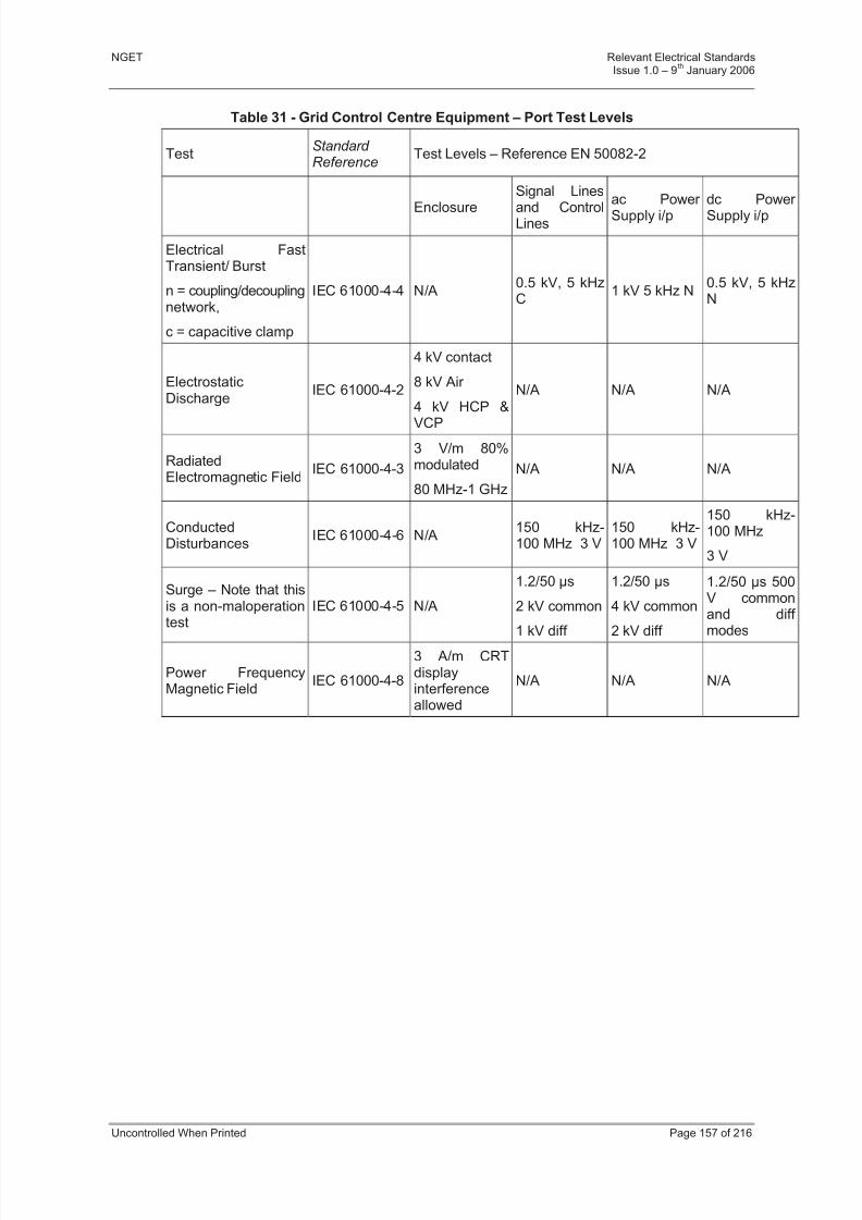
8/3/2019 1 Relevant Standards for Substation Plants
http://slidepdf.com/reader/full/1-relevant-standards-for-substation-plants 164/223
NGET Relevant Electrical StandardsIssue 1.0 – 9
thJanuary 2006
Uncontrolled When Printed Page 157 of 216
Table 31 - Grid Control Centre Equipment – Port Test Levels
TestStandard Reference
Test Levels – Reference EN 50082-2
Enclosure
Signal Lines
and ControlLines
ac Power Supply i/p
dc Power Supply i/p
Electrical FastTransient/ Burst
n = coupling/decouplingnetwork,
c = capacitive clamp
IEC 61000-4-4 N/A0.5 kV, 5 kHzC
1 kV 5 kHz N0.5 kV, 5 kHzN
ElectrostaticDischarge
IEC 61000-4-2
4 kV contact
8 kV Air
4 kV HCP &
VCP
N/A N/A N/A
RadiatedElectromagnetic Field
IEC 61000-4-3
3 V/m 80%modulated
80 MHz-1 GHz
N/A N/A N/A
ConductedDisturbances
IEC 61000-4-6 N/A150 kHz-100 MHz 3 V
150 kHz-100 MHz 3 V
150 kHz-100 MHz
3 V
Surge – Note that thisis a non-maloperation
test
IEC 61000-4-5 N/A
1.2/50 s
2 kV common
1 kV diff
1.2/50 s
4 kV common
2 kV diff
1.2/50 s 500V commonand diff
modes
Power FrequencyMagnetic Field
IEC 61000-4-8
3 A/m CRTdisplayinterferenceallowed
N/A N/A N/A
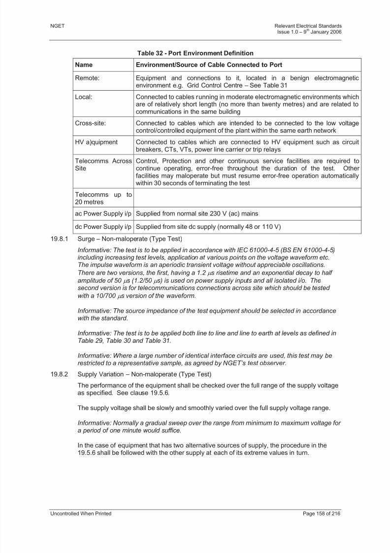
8/3/2019 1 Relevant Standards for Substation Plants
http://slidepdf.com/reader/full/1-relevant-standards-for-substation-plants 165/223
NGET Relevant Electrical StandardsIssue 1.0 – 9
thJanuary 2006
Uncontrolled When Printed Page 158 of 216
Table 32 - Port Environment Definition
Name Environment/Source of Cable Connected to Port
Remote: Equipment and connections to it, located in a benign electromagneticenvironment e.g. Grid Control Centre – See Table 31
Local: Connected to cables running in moderate electromagnetic environments whichare of relatively short length (no more than twenty metres) and are related tocommunications in the same building
Cross-site: Connected to cables which are intended to be connected to the low voltagecontrol/controlled equipment of the plant within the same earth network
HV a)quipment Connected to cables which are connected to HV equipment such as circuitbreakers, CTs, VTs, power line carrier or trip relays
Telecomms AcrossSite
Control, Protection and other continuous service facilities are required tocontinue operating, error-free throughout the duration of the test. Other facilities may maloperate but must resume error-free operation automaticallywithin 30 seconds of terminating the test
Telecomms up to20 metres
ac Power Supply i/p Supplied from normal site 230 V (ac) mains
dc Power Supply i/p Supplied from site dc supply (normally 48 or 110 V)
19.8.1 Surge – Non-maloperate (Type Test)
Informative: The test is to be applied in accordance with IEC 61000-4-5 (BS EN 61000-4-5)including increasing test levels, application at various points on the voltage waveform etc.The impulse waveform is an aperiodic transient voltage without appreciable oscillations.
There are two versions, the first, having a 1.2 s risetime and an exponential decay to half
amplitude of 50 s (1.2/50 s) is used on power supply inputs and all isolated i/o. The
second version is for telecommunications connections across site which should be tested
with a 10/700 s version of the waveform.
Informative: The source impedance of the test equipment should be selected in accordancewith the standard.
Informative: The test is to be applied both line to line and line to earth at levels as defined inTable 29, Table 30 and Table 31.
Informative: Where a large number of identical interface circuits are used, this test may berestricted to a representative sample, as agreed by NGET’s test observer.
19.8.2 Supply Variation – Non-maloperate (Type Test)
The performance of the equipment shall be checked over the full range of the supply voltageas specified. See clause 19.5.6.
The supply voltage shall be slowly and smoothly varied over the full supply voltage range.
Informative: Normally a gradual sweep over the range from minimum to maximum voltage for a period of one minute would suffice.
In the case of equipment that has two alternative sources of supply, the procedure in the19.5.6 shall be followed with the other supply at each of its extreme values in turn.
8/3/2019 1 Relevant Standards for Substation Plants
http://slidepdf.com/reader/full/1-relevant-standards-for-substation-plants 166/223
8/3/2019 1 Relevant Standards for Substation Plants
http://slidepdf.com/reader/full/1-relevant-standards-for-substation-plants 167/223
NGET Relevant Electrical StandardsIssue 1.0 – 9
thJanuary 2006
Uncontrolled When Printed Page 160 of 216
19.8.6 Electrical Fast Transient/Burst – Non-maloperate (Type Test)
Informative: The test is intended to simulate the effects of transient disturbances such asthose originating from switching transients (interruption of inductive loads, relay bounce etc).
The test shall be carried out in accordance with IEC 61000-4-4 and the levels to be applied
to the various ports are defined in Table 29, Table 30 and Table 31.
Informative: Where the EUT has a large number of identical interface circuits, the test may be restricted to an agreed sample.
19.8.7 Damped Oscillatory Wave – Non-maloperate (Type Test)
Informative: This test is intended to simulate the effects of switching with restrike of the arc (eg disconnector operation).
The tests are to be applied in accordance with IEC 61000-4-12.
Informative: Where the EUT has a large number of identical interface circuits, the test may be restricted to an agreed sample.
The 100 kHz and 1 MHz damped oscillatory wave test is to be applied at levels and to portsas defined in Table 29 and Table 30.
Informative: It is understood that IEC 61000-4-12 may be modified to include versions of thetest at other base frequencies. NGET has evidence that 10 kHz and 10 MHz versions of thisinterference are often present in the interference emanating from primary plant (10 kHz inthe case of AIS circuit breakers; 10 MHz from GIS disconnectors and circuit breakers and some AIS disconnectors).
When suitable test equipment is available the damped oscillatory wave test shall beextended to include the 10 kHz and 10 MHz versions of these tests.
19.8.8 Electrostatic Discharge – Non-maloperate (Type Test)Informative: This test is particularly relevant as it simulates the effect of large transient currents flowing adjacent to susceptible equipment or in the casing of the equipment. Suchcommon mode phenomena can occur in substations as a result of the operations of primary plant. For the substation environment therefore, the test should not just be regarded as atest that measures the susceptibility to discharges from personnel and furniture but as a test which gives an effective indication of the likely susceptibility of the equipment to thesubstation environment.
The test is based on IEC 61000-4-2. The level to be applied is dependent upon theenvironment in which the equipment is intended to be installed (see Table 29) and is to beapplied while the EUT is energised.
The test shall be undertaken on fully installed items of equipment, within their enclosures.
The test is to be applied to all points which are accessible during normal use.
The test is also to be applied to all points which are accessible during maintenance by theuser unless use of electrostatic precautions are provided for and mandated by anappropriate notice on the equipment.
Testing is to be carried out in accordance with the standard including the use of horizontaland vertical coupling planes where applicable.
The test voltage shall be increased from the minimum to the selected test level.
19.8.9 Radiated Radio Frequency Electromagnetic Field – Non-maloperate (Type and Site Pre-commissioning Test)

8/3/2019 1 Relevant Standards for Substation Plants
http://slidepdf.com/reader/full/1-relevant-standards-for-substation-plants 168/223
NGET Relevant Electrical StandardsIssue 1.0 – 9
thJanuary 2006
Uncontrolled When Printed Page 161 of 216
Informative: The objective of this test is to evaluate the performance of the equipment whensubjected to electromagnetic fields, primarily the transient fields generated by electricity supply plant but also the permanent fields generated by portable and base station radiotransceivers.
Informative: As the test applies the interference as a swept frequency its effectiveness in
simulating the transient interference from primary plant is limited. However this is the only standard radiated interference test which is available from the majority of test houses.
The performance of the EUT shall be monitored throughout the test.
The frequency range to be covered shall be 80 MHz to 1 GHz which is chosen tocomplement (and slightly overlap) that covered by the Conducted Disturbances test (q.v.).
Informative: The standard test as defined in BS EN 61000-4-3 covers frequencies up to 1GHz, modern digital cellular telephones (particularly the proposed Universal MobileTelephone System) extend up to 2.2 GHz.
When assessing equipment for use in substations in the vicinity of a base station or whereuninhibited use of mobile ‘phones is allowed, a sweep test at 10 V/m from 1.7 to 2.2 GHzshould be carried out in addition to the standard range of 80 MHz to 1.0 GHz.
The immunity to RFI is tested while the equipment is in its normal operating state with coversin place, and also with its covers removed for maintenance.
The testing shall be with the normal supply, input and output leads intended for theequipment.
The tests shall be conducted by persons experienced in the techniques involved and shall becarried out in a shielded room.
The test method shall be the radiating antenna method detailed in BS EN 61000-4-3 but withtest limits as defined in Table 29, Table 30 and Table 31.
The sweep rate shall be as specified in BS EN 61000-4-3, except that for digital equipmentthe rate shall be such that the EUT can perform 10 full operational cycles per octave.
At certain spot frequencies the EUT shall be required to carry out two full operational cycles.These spot frequencies shall be 80, 160, 450 and 900 MHz.
The addition of a further spot frequency test at 1.89 GHz will obviate the requirement to carryout the “Radiated Magnetic Field from Digital Portable Telephones Test”
An operational cycle shall include at least one transition of the EUT from one operational
state to another.
Informative: For example for protection equipment an operational cycle would includedetecting a (simulated) fault condition and generating a trip output.
If the equipment is mounted in cubicles, the tests shall be conducted with the antenna in linewith the centre of the back and then the front of the cubicle.
8/3/2019 1 Relevant Standards for Substation Plants
http://slidepdf.com/reader/full/1-relevant-standards-for-substation-plants 169/223
NGET Relevant Electrical StandardsIssue 1.0 – 9
thJanuary 2006
Uncontrolled When Printed Page 162 of 216
The testing shall initially be conducted with the cubicle doors open. If the equipment provesto be affected by RFI, the testing shall be repeated with the doors closed. If equipment in acubicle is susceptible to RFI when the cubicle doors are open, a label shall be affixed to thecubicle warning that radio transmitters should not be operated near the cubicle when thedoors are open.
The tests shall be conducted with the antenna in line with various faces of the equipment.
When an item of equipment is found to be susceptible to RFI, a note shall be made of thereduction of field strength which is required to reduce the susceptibility to acceptable limits.This need only be done at the most sensitive frequency.
19.8.10 Conducted Disturbances Induced by RF Fields – Non-maloperate (Type Test)
Informative: This purpose of this test is to determine the immunity of the EUT toelectromagnetic fields which act on the cables connected to the EUT.
The test is to be applied in accordance with IEC 61000-4-6.
The frequency range shall be by agreement but shall normally be 150 kHz to 100 MHz. Thetest is to be applied at levels and to ports as defined in Table 29, Table 30 and Table 31.
The sweep rate shall be as specified in BS EN 61000-4-6, except that for digital equipmentthe rate shall be such that the EUT can perform 10 full operational cycles per octave.
At certain spot frequencies the EUT shall be required to carry out two full operational cycles.These spot frequencies shall be 27 and 68 MHz.
An operational cycle shall include at least one transition of the EUT from one operationalstate to another.
Informative: For example for protection equipment an operational cycle would include
detecting a (simulated) fault condition and generating a trip output.
For equipment having a keyboard, mouse or similar manual interface unit, the test shall becarried out with and without an "artificial hand" as specified in IEC 61000-4-6
19.8.11 Mains Frequency Voltage
Informative: This test is intended to simulate the effect of an earth fault in the substation and to verify that the system is immune to any picked up mains frequency interference during non-fault conditions. The test method required is that specified in IEC 60255-22-7 which iscurrently in draft Ed.1. This standard is based on EN 61000-4-16 but includes a differential mode test, a current mode test for communication lines and uses different coupling capacitors and test voltages.
A test shall be applied to demonstrate that the EUT does not maloperate when a 50 Hzvoltage (in phase with the equipment supply for ac powered equipment) is applied via acapacitor.
The method as specified in EN 60255-22-7 shall be used using test levels as specified inTable 29 and Table
The method of application shall be one of those illustrated in Figures 2 to 5 of EN 60255-22-7, selected to suit the type of port being tested.
It should be noted that this test is not applicable to circuits for which 50 Hz inputs are normal.Where the EUT has a large number of identical interface circuits, the test may be restricted
to an agreed sample.

8/3/2019 1 Relevant Standards for Substation Plants
http://slidepdf.com/reader/full/1-relevant-standards-for-substation-plants 170/223
NGET Relevant Electrical StandardsIssue 1.0 – 9
thJanuary 2006
Uncontrolled When Printed Page 163 of 216
The test shall normally be restricted to 50 Hz unless additional frequencies are called up asa specific requirement of the contract. Note that this would normally be appropriate for equipment which is to be used in the proximity of power electronic equipment such as StaticVAR Compensators.
In the interim period, before IEC 60255-22-7 is formally issued, the method as specified in
EN 1000-4-16 shall be used unless otherwise agreed with NGET. The required test levelsare defined in Table 29.
19.8.12 Conducted Disturbance 15Hz to 150 kHz
Informative: This test simulates the effect of conducted disturbances which may begenerated by power electronic equipment.
The test shall be carried out in accordance with IEC 61000-4-16 using the test profile asdefined in Table 3 of that standard.
Application of the test should be considered for equipment to be installed on sitesincorporating power electronics e.g. SVCs.
19.8.13 Conducted and Radiated Emissions (Type Test)Informative: This test is intended to ensure that the EUT does not generate emissions at alevel that could cause other equipment to maloperate.
A conducted and radiated emissions test shall be carried out to check that the equipmentmeets the requirements of EN 55022 (BS 6527). Normally the acceptable limits shall betaken as those applicable to Class A equipment.
In the specific case where equipment is to be powered from a 48 V (dc) communicationsupply, self generated interference requirements are described by ETSI (EuropeanTelecommunication Standards Institute) standards ETS 300 132-2 , and ETS 300 386-1 asfollows:
a) Conducted emissions 25 Hz to 20 kHz ETS 300 132-2 Section 4.9
b) Conducted emissions 0.02 – 30 MHz ETS 300 386-1 Section 7.2.3
19.8.14 Inrush Current (Type Test)
Informative: Measurement of the inrush current shall preferably be made using a Hall effect current clamp having a frequency response up to at least 3 kHz. Alternatively, the current may be measured using a low value series resistor, such that at peak current the voltageacross it does not exceed 5% of the supply voltage.
Informative: The tests shall be performed with the equipment operating under conditions of maximum power consumption.
Informative: An interval of several minutes shall be allowed to elapse between each test.
Informative: Every effort shall be made to ensure that the supply source impedance does not significantly limit the inrush current.
Informative: The current waveform shall be recorded after switch-on until it has reached asteady value, and a note shall be made on the trace of the points where peak and zerovalues of the waveform occur. For ac supplies, not less than ten measurements shall berecorded.

8/3/2019 1 Relevant Standards for Substation Plants
http://slidepdf.com/reader/full/1-relevant-standards-for-substation-plants 171/223
NGET Relevant Electrical StandardsIssue 1.0 – 9
thJanuary 2006
Uncontrolled When Printed Page 164 of 216
19.8.15 Power Frequency Magnetic Field Immunity – Non-maloperate (Type Test)
Informative: This test would normally only be applied to equipment which utilises an electronbeam (eg Cathode Ray Tube Monitors, Electron Microscopes etc) or to certain measuring instruments. However the test is also called up in EN 60870-2-1 and is therefore availableas an additional test for other equipment at levels as specified in Table 30.
The test shall be carried out in accordance with IEC 61000-4-8 in all three planes of theEUT.
The continuous and short duration tests shall be applied to equipment which is to be locatedwithin 5 metres of any grid transformer. The test levels are specified in Table 30.
For CRT monitors for use in a substation the level is specified in Table 30. No visible effectshall result at this level and below (Class 1 results as specified in IEC 61000-4-8).
19.8.16 Pulsed Magnetic Field – Non-maloperate (Type Test)
Informative: This test simulates the magnetic field generated by a) lightning strokes, b) initial fault transients and c) the switching of HV busbars and lines by circuit breakers. Research
carried out for NGET has concluded that the test is of most relevance in the case of a)above.
The test shall be carried out in accordance with IEC 61000-4-9 at test levels as specified inTable 30.
The Pulsed Magnetic Field test shall be applied to equipment which can directly cause theopening of a circuit breaker and is to be positioned in a high lightning risk area.
19.8.17 Damped Oscillatory Magnetic Field – Non-maloperate (Type Test)
Informative: Damped Oscillatory Magnetic Fields are generated by the switching of HV busbars by disconnectors. The test as specified in IEC 61000-4-10 requires oscillatory waves of 0.1 and 1.0 MHz. NGET has evidence that 10 kHz and 10 MHz versions of this
waveform are also often present in the spectrum of the interference emanating from primary plant (10 kHz in the case of AIS circuit breakers; 10 MHz from GIS disconnectors and circuit breakers and some AIS disconnectors). The field is confined to the vicinity of the current breaking device.
The Damped Oscillatory Magnetic Field test is required for equipment located within 10metres of circuit breakers or disconnectors. When test equipment is available the test is alsoto be applied at 10 kHz and 10 MHz in addition to the 0.1 and 1.0 MHz specified in thestandard. The test levels are specified in Table .
19.8.18 Dielectric and Insulation Resistance – Withstand (Type, Routine and Sample Test)
Informative: The objective of these tests which are based on IEC 60255-5 is to prove theintegrity of the insulation and isolation between each circuit and exposed conductive parts
(including earth) and between independent circuits. The tests involve the measurement of insulation resistance and the application of a dielectric withstand test as described below.
The type test is only to be applied to isolation and safety barriers.
Other items (eg PSUs) are to be tested during the manufacturing process (routine andsample) before filters, over-voltage protection devices etc are installed. In this case, for typeregistration, evidence must be produced that the power supply unit conforms with, for example, IEC 478 Stabilised Power Supplies – (dc) Output.
For circuits operating at voltages of 110 V (ac) or (dc) and above, or where a circuit isenergised via an instrument transformer, a dielectric withstand test of 2 kV (ac) and aninsulation resistance test of 500 V (dc) shall be performed.
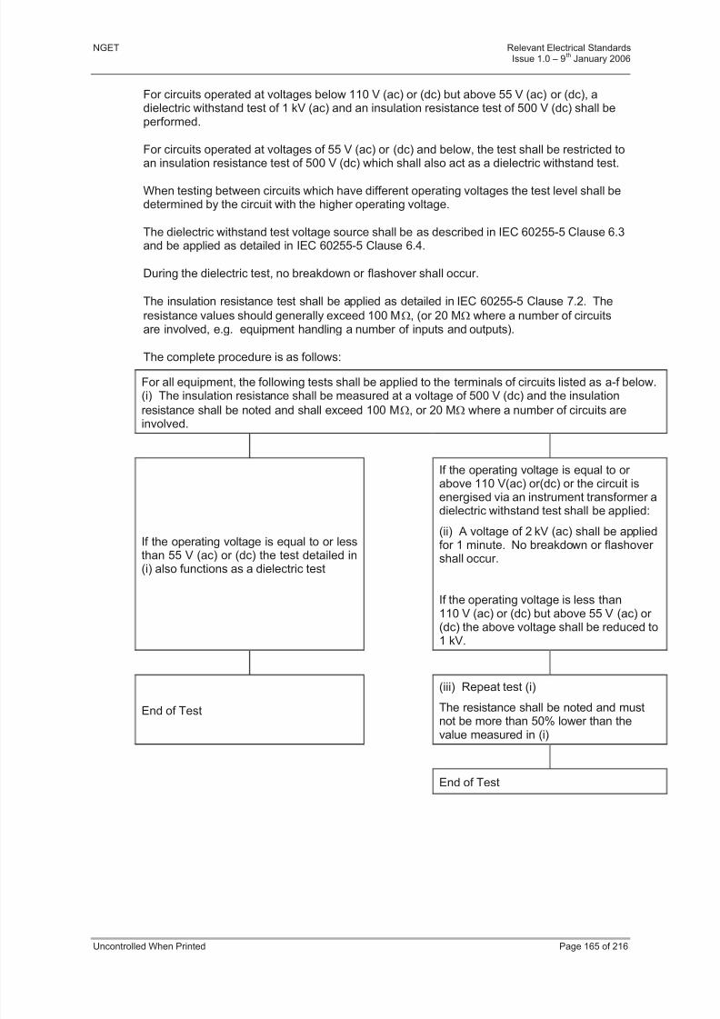
8/3/2019 1 Relevant Standards for Substation Plants
http://slidepdf.com/reader/full/1-relevant-standards-for-substation-plants 172/223
NGET Relevant Electrical StandardsIssue 1.0 – 9
thJanuary 2006
Uncontrolled When Printed Page 165 of 216
For circuits operated at voltages below 110 V (ac) or (dc) but above 55 V (ac) or (dc), adielectric withstand test of 1 kV (ac) and an insulation resistance test of 500 V (dc) shall beperformed.
For circuits operated at voltages of 55 V (ac) or (dc) and below, the test shall be restricted toan insulation resistance test of 500 V (dc) which shall also act as a dielectric withstand test.
When testing between circuits which have different operating voltages the test level shall bedetermined by the circuit with the higher operating voltage.
The dielectric withstand test voltage source shall be as described in IEC 60255-5 Clause 6.3and be applied as detailed in IEC 60255-5 Clause 6.4.
During the dielectric test, no breakdown or flashover shall occur.
The insulation resistance test shall be applied as detailed in IEC 60255-5 Clause 7.2. The
resistance values should generally exceed 100 M, (or 20 M where a number of circuitsare involved, e.g. equipment handling a number of inputs and outputs).
The complete procedure is as follows:
For all equipment, the following tests shall be applied to the terminals of circuits listed as a-f below.(i) The insulation resistance shall be measured at a voltage of 500 V (dc) and the insulation
resistance shall be noted and shall exceed 100 M, or 20 M where a number of circuits areinvolved.
If the operating voltage is equal to or lessthan 55 V (ac) or (dc) the test detailed in(i) also functions as a dielectric test
If the operating voltage is equal to or above 110 V(ac) or(dc) or the circuit isenergised via an instrument transformer adielectric withstand test shall be applied:
(ii) A voltage of 2 kV (ac) shall be appliedfor 1 minute. No breakdown or flashover shall occur.
If the operating voltage is less than110 V (ac) or (dc) but above 55 V (ac) or (dc) the above voltage shall be reduced to1 kV.
End of Test
(iii) Repeat test (i)
The resistance shall be noted and mustnot be more than 50% lower than thevalue measured in (i)
End of Test
8/3/2019 1 Relevant Standards for Substation Plants
http://slidepdf.com/reader/full/1-relevant-standards-for-substation-plants 173/223
NGET Relevant Electrical StandardsIssue 1.0 – 9
thJanuary 2006
Uncontrolled When Printed Page 166 of 216
Tests shall be applied between the following terminals:
a) Each isolated input to exposed conductive parts, including earth.
b) Each isolated input to all other inputs connected together.
c) Each isolated output to exposed conductive parts, including earth.
d) Each isolated output to all other outputs connected together.
e) All isolated inputs connected together to all isolated outputs connected together.
f) The power supply to all isolated inputs, isolated outputs, and exposed conductiveparts, including earth.
19.8.19 Electrical Supply Variation and Interruption – Non-maloperate (Site Pre-commissioning Test)
Where variable supply conditions exist on site, the equipment shall be tested over the fullrange of change, site conditions permitting.
19.8.20 Supply Changeover (Site Pre-commissioning Test)
Where supply interruptions can occur on site due to changeover, the installed equipmentshall be tested to demonstrate its compatibility with the changeover requirements.
19.8.21 Electrical Noise (Site Pre-commissioning Test)
Equipment may be required to undergo noise tests on site. The tests may involve theoperation of high voltage switchgear and/or a special injection test.
19.9 ATMOSPHERIC ENVIRONMENTAL TESTS
19.9.1 Dry Heat – Non-maloperate (Type Test)
The dry heat test shall be carried out on individual subunits, units and, where applicable, on
the complete equipment or assembly, with all doors and covers being in place and closed asin normal operation.
Test conditions shall be in accordance with IEC 68-2-2 (EN 60068-2-2), test Bd at the upper temperature of the Environmental Class (±2ºC, RH 60%)
For Class 1 or Class 2 equipment which is to be used in a cabinet not included in the EUT,the test shall be carried out at 15 ºC above the Class temperature.
The EUT shall operate continuously during the test.
The duration of the test would normally be 16 hours (excluding acclimatisation time) exceptfor equipment which can directly cause the opening or closing of a circuit breaker which shall
be subjected to either 55 ºC for 96 hours or 70 ºC for 16 hours. (The additional 15 Cenclosure factor need not be applied).
Performance checks shall be made at least three times at regular periods while at the testtemperature and repeated when the equipment has returned to ambient temperature.
8/3/2019 1 Relevant Standards for Substation Plants
http://slidepdf.com/reader/full/1-relevant-standards-for-substation-plants 174/223
NGET Relevant Electrical StandardsIssue 1.0 – 9
thJanuary 2006
Uncontrolled When Printed Page 167 of 216
19.9.2 Low Temperature – Non-maloperate (Type Test)
The low temperature test shall be carried out on individual subunits, units and, whereapplicable, on the complete equipment or assembly, with all doors and covers being in placeand closed as in normal operation.
Test conditions shall be in accordance with IEC 68-2-1 (EN 60068-2-2), test Ad at the lower temperature of the Environmental Class (±2ºC, RH 60%.
The EUT shall operate continuously during the test.
The duration of the test would normally be 16 hours (excluding acclimatisation time) exceptfor equipment which can directly cause the opening or closing of a circuit breaker which shallbe subjected to either -10ºC for 96 hours or -25ºC for 16 hours.
Performance checks shall be made at least three times at regular periods while at the testtemperature and repeated when the equipment has returned to ambient temperature.
19.9.3 Damp Heat – Non-maloperate (Type Test)
This test is undertaken on complete items of equipment in their normal operational mode.The test is based on IEC 68-2-56 (BS 2011-2.1Cb) Test BC which is designed to avoid theformation of condensation on the EUT. The following conditions shall apply:
a) The test duration shall be 2 days except where noted below and unless a longer period is specified.
b) The test conditions shall be 40 ±2 ºC with 93 ±3% RH; except for equipment whichcan directly cause the opening or closing of a circuit breaker which shall be subjectedto either IEC 68-2-3 at 40 ±2 ºC with 93 ±3% RH for 56 days, or IEC 68-2-30 for 6times 24 hour cycles of + 25 ºC to +55 ºC with 93 ±3% RH.
c) The initial performance check shall be made with the equipment under ambientconditions in the test chamber. In the case of tests to IEC 68-2-56, the equipmentshall be switched off on completion of this check.
d) In the case of tests to IEC 68-2-56 after test conditions have been achieved, theequipment shall be re-energised two hours before test conditions are allowed to alter and a further performance check carried out during the last hour at the elevatedtemperature and humidity. The equipment shall remain energised for the remainder of the test.
e) Single chamber controlled recovery conditions shall be applied, after which the finalperformance check shall be made.
19.9.4 Storage Temperature Test – Withstand (Type Test)
Unless otherwise agreed, all electronic equipment shall be subjected to a withstand test tosimulate the extreme temperature ranges which can be encountered during storage andtransportation.
The equipment shall be subjected to a low temperature test in accordance with IEC 68-2-1 at-25ºC for 96 hours or -40ºC for 16 hours. The EUT shall also be subjected to a hightemperature test according to IEC 68-2-2 at 70ºC for 96 hours.
After ambient conditions are re-established a Performance Check shall be performed.

8/3/2019 1 Relevant Standards for Substation Plants
http://slidepdf.com/reader/full/1-relevant-standards-for-substation-plants 175/223

8/3/2019 1 Relevant Standards for Substation Plants
http://slidepdf.com/reader/full/1-relevant-standards-for-substation-plants 176/223
8/3/2019 1 Relevant Standards for Substation Plants
http://slidepdf.com/reader/full/1-relevant-standards-for-substation-plants 177/223
NGET Relevant Electrical StandardsIssue 1.0 – 9
thJanuary 2006
Uncontrolled When Printed Page 170 of 216
The test shall be carried out in accordance with IEC 68-2-6. The EUT shall be subjected tothe vibration response test at severity class 1 and the vibration withstand test at severityclass 1.These test levels are defined in the related standard EN 60255-21-1.
As far as possible, the equipment shall be mounted on its normal fixings and the vibrationsshall be applied along each axis in turn. If necessary, to observe otherwise obscured parts,
equipment sub-assemblies may also be tested. Equipment may be required to undergo aperformance check while being subjected to a sweep frequency test.
When a resonance is detected, a search shall be made on either side of the resonantfrequency so that the effects of the resonance may be assessed.
Any resonances liable to affect the performance or reliability of the equipment shall bereduced to an acceptable level by suitable modifications, and the test repeated.
19.10.3 Shock (Type Test)
A shock test shall be carried out in accordance with IEC 68-2-27. The EUT shall besubjected to the shock response test at severity class 1 and the shock withstand test atseverity class 1. These test levels are defined in the related standard EN 60255-21-2.
19.10.4 Bump (Type Test)
A bump test shall be carried out in accordance with IEC68-2-29. The EUT shall besubjected to the bump test at severity class 1. These test levels are defined in the relatedstandard EN 60255-21-2.
19.10.5 Seismic (Type Test)
A seismic test at severity class 1 shall be carried out in accordance with EN 60255-21-3.

8/3/2019 1 Relevant Standards for Substation Plants
http://slidepdf.com/reader/full/1-relevant-standards-for-substation-plants 178/223
NGET Relevant Electrical StandardsIssue 1.0 – 9
thJanuary 2006
Uncontrolled When Printed Page 171 of 216
20 SECTION 17 - GAS INSULATED SWITCHGEAR
20.1 PURPOSE AND SCOPE
This document defines the functional and performance requirements for gas-insulated
switchgear (GIS) for use on the Transmission System in England and Wales. It supports themore general requirements defined in Part 4, Sections 1,2 and 3.
In addition to busbars and connectors, GIS includes individual components for whichseparate standards and specifications apply. This document complements the requirementsfor these components specified in the relevant standards and specifications.
20.2 GENERAL REQUIREMENTS
Gas-insulated switchgear (GIS) shall comply with IEC 62271-203
Pressurised gas-filled enclosures shall comply with the following CENELEC standards:
EN 50-052EN 50-064BS EN 50-068BS EN 50-069
Cast resin partitions shall comply with CENELEC Standard EN 50-089.
20.2.1 Outage Constraints
The design of the equipment shall allow the outage constraint requirements of Part 4,Section 2 to be met. It shall be possible to perform foreseeable activities includingmaintenance (including replacement of any enclosure and any necessary dismantling of equipment), circuit breaker timing, primary injection tests on CTs and the construction andtesting of substation extensions while meeting the above requirements. It shall be possibleto perform such activities without the need to work adjacent to a gas compartment partition
when pressurised on one side. The supplier shall demonstrate by means of gas zonediagrams or otherwise, how compliance with the outage constraint requirements of Part 4,Section 2 can be achieved.
20.2.2 Earthing Switches
Earthing switches of class E1 as defined in IEC 62271-102 shall be provided on the circuitside of each line disconnector and at one position on each section of busbar.
Earthing switches installed at positions where the only means of dissipating trapped chargeis by closing the earthing switch shall be capable of remote operation.
Informative: This is where a de-energised section of GIS cannot be connected to any of thefollowing: Power transformer/shunt reactor winding; electromagnetic VT on all three phases
or external air insulated equipment (bushings, etc).
20.2.3 Portable Maintenance Earthing Devices
Provision shall be made for fitting portable maintenance earthing devices (PMEDs) wherethese are required to permit maintenance/testing as follows:
a) To allow an earthing switch that would normally be the point of earthing to be itself maintained.
b) To earth cable terminations where disconnecting facilities are provided for cabletesting.
c) To provide an earth connection where a section of busbar is removed.
d) To provide an earth connection visible from the point of work.
8/3/2019 1 Relevant Standards for Substation Plants
http://slidepdf.com/reader/full/1-relevant-standards-for-substation-plants 179/223
NGET Relevant Electrical StandardsIssue 1.0 – 9
thJanuary 2006
Uncontrolled When Printed Page 172 of 216
The positions on the GIS at which PMEDs may be fitted shall be clearly identified by paintingin a conspicuous colour/pattern or other means of equivalent durability.
The PMEDs shall be clearly visible when applied by painting in a conspicuous colour/patternor other means of equivalent durability.
20.2.4 SF6 Gas Service ConnectionsThe gas service connection for each gas compartment shall be readily accessible without theuse of special access equipment.
A schematic diagram shall be provided showing the gas compartments within a bay and their relationship to the primary plant of that circuit or busbar section.
Filling points shall be fitted with self-sealing valves.
A lockable arrangement to prevent unauthorised operation of the gas service valves shall beprovided at each filling point.
20.2.5 Pressure/Density Indication
A permanently installed system for monitoring the gas pressure or density in eachcompartment shall be provided.
The system shall provide a visual indication of the gas pressure or density in each gascompartment.
The system shall be capable of initiating gas density alarms at user configurable trigger levels.
The system shall be capable of detecting a gas loss equivalent to 0.5 % of the gascompartment volume per annum or shall provide trend analysis facilities.
It shall be possible to replace a pressure or density sensor without taking the GIS out of service.
20.2.6 SF6 Gas Alarm Scheme
Provision shall be made for connection of each gas density alarm to the substation alarmscheme.
Facilities shall be provided to allow temporary blocking of the density alarm signals from anindividual gas compartment so that grouped alarms are not initiated.
Informative: The objective is to ensure that, during maintenance of primary equipment,standing common alarms do not mask genuine SF6 density alarms from in-serviceequipment. This is particularly important where a disconnector gas compartment forming the‘point of isolation’ for work would normally initiate the same common SF6 density alarm asthe compartment that has been opened for maintenance.
The grouping of ‘low’ alarms at the normal substation control point shall be such that thesection of the substation that requires isolation from the system can be readily identified.
Informative: For example, in the case of a circuit (‘circuit 1’) connected in a double busbar configuration, there are five possible alarm conditions:
Low gas on the circuit side of the busbar selector disconnectors (Alarm: Circuit 1 SF6 gaslow)
Low gas on the MBB side of the busbarr selector disconnectors (Alarm: MBB SF6 gas low)
Low gas on the RBB side of the busbar selector disconnectors (Alarm: RBBG SF6 gas low)
8/3/2019 1 Relevant Standards for Substation Plants
http://slidepdf.com/reader/full/1-relevant-standards-for-substation-plants 180/223
NGET Relevant Electrical StandardsIssue 1.0 – 9
thJanuary 2006
Uncontrolled When Printed Page 173 of 216
Low gas in the MBB busbar selector disconnector (Alarm: MBB SF6 gas low and Circuit 1SF6 gas low)
Low gas in the RBB busbar selector disconnector (Alarm: RBB SF6 gas low and Circuit 1gas low)
Suppliers shall identify where leakage of gas from a higher pressure gas compartment to anadjacent lower pressure gas compartment may result in operation of the pressure relief device of the lower pressure compartment. In these cases the lower pressure compartmentshall be fitted with a high density alarm.
Provision for checking gas monitoring devices shall be achieved in such a way that operationof as much of the alarm circuit as is reasonably practicable be confirmed. Safe access for performing this check shall be provided.
Informative: For disconnector gas compartments this check must be performed to confirmintegrity of a ‘point of isolation’ during switching to achieve safety from the system.
Informative: It will always be practicable to provide a facility to reduce the SF6 pressure at the primary sensor. Any design proposal that does not allow for testing from this point must therefore be justified on the basis of reduced costs and a low probability of failure of theuntested elements.
Informative: Where the primary sensor is a transducer, then a good case can generally bemade that testing from the input terminals of the monitoring unit is adequate on the groundsthat any credible transducer failure would initiate an alarm condition.
GIS disconnectors shall be provided with lockout facilities to prevent operation at less thanthe minimum functional pressure or density.
Informative: This is to prevent the equipment from being operated beyond its strength and
capability.20.2.7 Pressure Relief
Pressure relief devices shall be installed so as to eject debris away from normally accessibleareas. They shall be set to minimise danger to personnel.
20.2.8 Identification of Pipework
Fixed gas and hydraulic pipework shall be identified in accordance with BS 1710.
20.2.9 Identification of Gas Compartment Partitions
The position of each gas compartment partition shall be clearly identified.
Labels shall be fixed to the enclosure at each gas compartment partition showing the
identifier of the gas compartments at each side of that partition.
20.2.10 Primary Injection Testing of CTs
Provision shall be made for carrying out primary injection tests on all current transformerswithout requiring internal access to any gas compartment.
20.2.11 Partial Discharge Measurement
For GIS equipment for use at 275 kV and above, capacitive couplers for diagnosticmonitoring of the GIS equipment and transient voltage measurements shall be provided in allphases at the following positions:
a) The sealing ends of each cable connected circuit.
b) The SF6 side of each transformer bushing.

8/3/2019 1 Relevant Standards for Substation Plants
http://slidepdf.com/reader/full/1-relevant-standards-for-substation-plants 181/223
NGET Relevant Electrical StandardsIssue 1.0 – 9
thJanuary 2006
Uncontrolled When Printed Page 174 of 216
c) Adjacent to the SF6/air bushings of each circuit connected to AIS equipment.
d) At intervals between these points such that all parts of the GIS shall be between twocouplers and that the required sensitivity specified in Clause 20.3.5 shall be achieved.
Informative: Where gas insulated busbar connections are greater than approximately 20 m
in length, it is often acceptable to increase the distance between couplers compared withGIS due to the reduced levels of signal attenuation.
To facilitate the use of couplers for in-service monitoring, coupler signal connections shall becabled so as to be accessible from ground level. Where located outdoors, test boxesconforming to IP65 of BS EN 60529 shall be provided.
The signal cables and the connections shall be identified according to the associated coupler and phase. The signal propagation time of each cable shall also be marked.
Signal connections shall be N series 50 Ohm sockets.
Signal cables between the couplers and test boxes shall be double screened co-axial.
20.3 PERFORMANCE REQUIREMENTS
20.3.1 Rated Insulation Level
For the point of isolation for cable testing and any parts of the switchgear that remainconnected to the cable termination during the test, the withstand voltages detailed inTable 33 shall apply.
145 kV 300 kV 420 kV
15 minute withstand test voltage to earth andwhere appropriate between phases, kV D.C.
335 580 780
Table 33 - DC withstand voltages
20.3.2 Performance at 0 Bar Gauge (barg)
GIS circuit breakers and disconnectors shall be able to withstand two fully asynchronouspower frequency voltages applied to the opposite terminals of the same pole when in theOPEN position with each voltage equal to the rated phase to earth power frequency voltagewhen filled with the insulating gas at a pressure of 0 barg.
GIS equipment shall be able to withstand 1.5 times the rated phase to earth power frequencyvoltage between its conducting parts and earth and, where appropriate, between phases for a duration of 1 minute when filled with the insulating gas at a pressure of 0 barg.
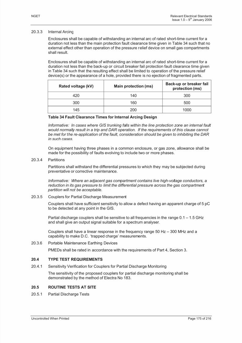
8/3/2019 1 Relevant Standards for Substation Plants
http://slidepdf.com/reader/full/1-relevant-standards-for-substation-plants 182/223
NGET Relevant Electrical StandardsIssue 1.0 – 9
thJanuary 2006
Uncontrolled When Printed Page 175 of 216
20.3.3 Internal Arcing
Enclosures shall be capable of withstanding an internal arc of rated short-time current for aduration not less than the main protection fault clearance time given in Table 34 such that noexternal effect other than operation of the pressure relief device on small gas compartmentsshall result.
Enclosures shall be capable of withstanding an internal arc of rated short-time current for aduration not less than the back-up or circuit breaker fail protection fault clearance time givenin Table 34 such that the resulting effect shall be limited to operation of the pressure relief device(s) or the appearance of a hole, provided there is no ejection of fragmented parts.
Rated voltage (kV) Main protection (ms)Back-up or breaker fail
protection (ms)
420 140 300
300 160 500
145 200 1000
Table 34 Fault Clearance Times for Internal Arcing Design
Informative: In cases where GIS trunking falls within the line protection zone an internal fault would normally result in a trip and DAR operation. If the requirements of this clause cannot be met for the re-application of the fault, consideration should be given to inhibiting the DAR in such cases.
On equipment having three phases in a common enclosure, or gas zone, allowance shall bemade for the possibility of faults evolving to include two or more phases.
20.3.4 Partitions
Partitions shall withstand the differential pressures to which they may be subjected duringpreventative or corrective maintenance.
Informative: Where an adjacent gas compartment contains live high-voltage conductors, areduction in its gas pressure to limit the differential pressure across the gas compartment partition will not be acceptable.
20.3.5 Couplers for Partial Discharge Measurement
Couplers shall have sufficient sensitivity to allow a defect having an apparent charge of 5 pCto be detected at any point in the GIS.
Partial discharge couplers shall be sensitive to all frequencies in the range 0.1 – 1.5 GHzand shall give an output signal suitable for a spectrum analyser.
Couplers shall have a linear response in the frequency range 50 Hz – 300 MHz and a
capability to make D.C. ‘trapped charge’ measurements.
20.3.6 Portable Maintenance Earthing Devices
PMEDs shall be rated in accordance with the requirements of Part 4, Section 3.
20.4 TYPE TEST REQUIREMENTS
20.4.1 Sensitivity Verification for Couplers for Partial Discharge Monitoring
The sensitivity of the proposed couplers for partial discharge monitoring shall bedemonstrated by the method of Electra No 183.
20.5 ROUTINE TESTS AT SITE
20.5.1 Partial Discharge Tests
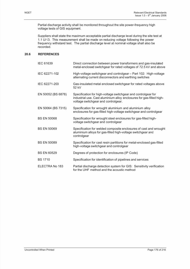
8/3/2019 1 Relevant Standards for Substation Plants
http://slidepdf.com/reader/full/1-relevant-standards-for-substation-plants 183/223
NGET Relevant Electrical StandardsIssue 1.0 – 9
thJanuary 2006
Uncontrolled When Printed Page 176 of 216
Partial discharge activity shall be monitored throughout the site power-frequency highvoltage tests of GIS equipment.
Suppliers shall state the maximum acceptable partial discharge level during the site test at
1.1 U/3. This measurement shall be made on reducing voltage following the power frequency withstand test. The partial discharge level at nominal voltage shall also be
recorded.
20.6 REFERENCES
IEC 61639 Direct connection between power transformers and gas-insulatedmetal-enclosed switchgear for rated voltages of 72.5 kV and above
IEC 62271-102 High-voltage switchgear and controlgear – Part 102: High-voltagealternating current disconnectors and earthing switches
IEC 62271-203 Gas-insulated metal enclosed switchgear for rated voltages above52 kV
EN 50052 (BS 6878) Specification for high-voltage switchgear and controlgear for industrial use. Cast aluminium alloy enclosures for gas-filled high-voltage switchgear and controlgear.
EN 50064 (BS 7315) Specification for wrought aluminium and aluminium alloyenclosures for gas-filled high-voltage switchgear and controlgear
BS EN 50068 Specification for wrought steel enclosures for gas-filled high-voltage switchgear and controlgear
BS EN 50069 Specification for welded composite enclosures of cast and wroughtaluminium alloys for gas-filled high-voltage switchgear andcontrolgear
BS EN 50089 Specification for cast resin partitions for metal-enclosed gas-filledhigh-voltage switchgear and controlgear
BS EN 60529 Degrees of protection for enclosures (IP Code)
BS 1710 Specification for identification of pipelines and services
ELECTRA No 183 Partial discharge detection system for GIS: Sensitivity verificationfor the UHF method and the acoustic method

8/3/2019 1 Relevant Standards for Substation Plants
http://slidepdf.com/reader/full/1-relevant-standards-for-substation-plants 184/223
NGET Relevant Electrical StandardsIssue 1.0 – 9
thJanuary 2006
Uncontrolled When Printed Page 177 of 216
PART 5 - GUIDANCE NOTES
21 SECTION 1 - TYPE REGISTRATION
21.1 PURPOSE AND SCOPE
Type Registration is a documented, risk managed process which enables NGET to verifythat plant, equipment and apparatus purchased for use on, or directly connected to, theTransmission System in England and Wales complies with NGET’s technical requirements,IEC or other relevant specifications and are therefore deemed suitable for their intendedapplication.
This document gives guidance to NGET contractors in order to ensure that the requirementsof the Type Registration process are met.
The process is applicable to, but not limited to, primary and secondary equipment sub-system solutions only. Individual components, which form part of the sub-system solution,
will not be separately registered.
In this context, a sub-system solution is defined as the largest functional assembly that canbe connected to the Transmission System in England and Wales taking into account design,testing, procurement and lifetime management constraints. A list of sub-system solutions towhich this process applies is given below: -
a) Standard bay designs
b) Light current bays
c) Mechanically Switched Capacitor Damping Networks (MSCDN)
d) Power Transformers
e) Cable systems
f) DC systems
g) Static Var Compensators (SVC)
h) Quad Boosters
i) Shunt and Series Reactors
j) Air ring main systems
k) Telecommunication systems
l) OHL conductor and OPGW systems
m) OHL insulator systems
Where individual components are procured directly by NGET, separate arrangements willapply. In this case the component supplier will be required to submit documentation asdefined in Part 3, Section 1 of this document for assessment by NGET Asset Policy in order to demonstrate suitability for the intended application, fitness for purpose and compliancewith the relevant technical requirements.
Subject to satisfactory assessment, NGET will issue an asset code to the componentsupplier to indicate that the product may be purchased by NGET.PART 1 – procedural
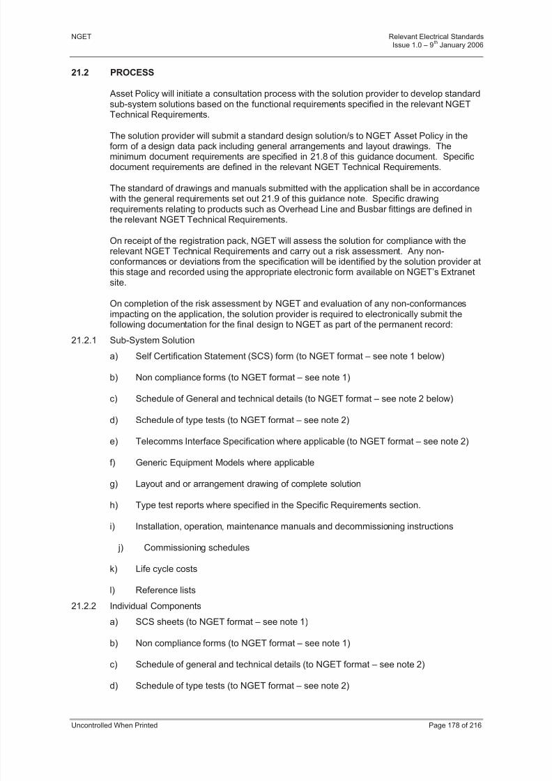
8/3/2019 1 Relevant Standards for Substation Plants
http://slidepdf.com/reader/full/1-relevant-standards-for-substation-plants 185/223
NGET Relevant Electrical StandardsIssue 1.0 – 9
thJanuary 2006
Uncontrolled When Printed Page 178 of 216
21.2 PROCESS
Asset Policy will initiate a consultation process with the solution provider to develop standardsub-system solutions based on the functional requirements specified in the relevant NGETTechnical Requirements.
The solution provider will submit a standard design solution/s to NGET Asset Policy in theform of a design data pack including general arrangements and layout drawings. Theminimum document requirements are specified in 21.8 of this guidance document. Specificdocument requirements are defined in the relevant NGET Technical Requirements.
The standard of drawings and manuals submitted with the application shall be in accordancewith the general requirements set out 21.9 of this guidance note. Specific drawingrequirements relating to products such as Overhead Line and Busbar fittings are defined inthe relevant NGET Technical Requirements.
On receipt of the registration pack, NGET will assess the solution for compliance with therelevant NGET Technical Requirements and carry out a risk assessment. Any non-conformances or deviations from the specification will be identified by the solution provider at
this stage and recorded using the appropriate electronic form available on NGET’s Extranetsite.
On completion of the risk assessment by NGET and evaluation of any non-conformancesimpacting on the application, the solution provider is required to electronically submit thefollowing documentation for the final design to NGET as part of the permanent record:
21.2.1 Sub-System Solution
a) Self Certification Statement (SCS) form (to NGET format – see note 1 below)
b) Non compliance forms (to NGET format – see note 1)
c) Schedule of General and technical details (to NGET format – see note 2 below)
d) Schedule of type tests (to NGET format – see note 2)
e) Telecomms Interface Specification where applicable (to NGET format – see note 2)
f) Generic Equipment Models where applicable
g) Layout and or arrangement drawing of complete solution
h) Type test reports where specified in the Specific Requirements section.
i) Installation, operation, maintenance manuals and decommissioning instructions
j) Commissioning schedules
k) Life cycle costs
l) Reference lists
21.2.2 Individual Components
a) SCS sheets (to NGET format – see note 1)
b) Non compliance forms (to NGET format – see note 1)
c) Schedule of general and technical details (to NGET format – see note 2)
d) Schedule of type tests (to NGET format – see note 2)

8/3/2019 1 Relevant Standards for Substation Plants
http://slidepdf.com/reader/full/1-relevant-standards-for-substation-plants 186/223
NGET Relevant Electrical StandardsIssue 1.0 – 9
thJanuary 2006
Uncontrolled When Printed Page 179 of 216
e) Calculation sheets where required by relevant NGET technical specification (to NGETformat – see note 2)
f) General arrangement drawings, key assembly drawings and schematic diagrams
g) Type test reports where specified in the relevant Specific Requirements section.
h) Installation, operation, maintenance manuals and decommissioning instructions
i) Commissioning schedules
Note 1 Templates are available on the Extranet web-site under TGN, forms
Note 2 Templates associated with the relevant NGET Technical Requirements areavailable on the Extranet web-site under NGT S schedules. Completed formsmust be submitted to NGET in their original format.
The solution provider is responsible for collating, assessing the component supplier’s SCSstatements and submitting them to NGET as required by the type registration process. Therelevant NGET Technical Requirement and issue number shall be stated on the SCS in allcases.
In submitting these statements, the solution provider shall declare that the sub-system andcomponents which comprise the solution are fit for the application for which it is intended andhave the strength and capability under the Electricity and Work regulations and relevant UKstatutes.
Any non-conformances or deviations from the specification shall be identified at this stageand recorded using the appropriate electronic form available on NGET’s Extranet site.
Test evidence in the form of type test reports and calculations shall be submitted
electronically in English language. All tests shall have been performed in accordance withcurrent European, IEC or British standards and specifications.
It is the responsibility of the solution provider to satisfy themselves that test evidenceprovided has been either verified independently or completed by a person or persons withthe appropriate skills, knowledge and experience operating to a recognised qualityprocedure. NGET reserves the right to seek independent witnessing/validation when inNGET’s opinion it is appropriate and required.
Calculations will only be accepted in lieu of testing where permitted by the specification or where this cannot practically be verified by direct testing.

8/3/2019 1 Relevant Standards for Substation Plants
http://slidepdf.com/reader/full/1-relevant-standards-for-substation-plants 187/223
NGET Relevant Electrical StandardsIssue 1.0 – 9
thJanuary 2006
Uncontrolled When Printed Page 180 of 216
21.2.3 Test reports offered in support of the type registration applications shall:
a) Include references to all applied standard(s) including level of conformance
b) Clearly and unambiguously identify the test parameters and pass/fail criteria
c) Explicitly detail all deviations of test procedure and parameters from the referencedstandard(s) and associated guidance
d) Clearly state the outcome of the test (pass/fail/unclear) and close out of any failureand details of re-testing
e) Contain sufficient information to fully identify all relevant aspects of the testedcomponent and the tested configuration
f) Contain sufficient information to identify the condition of the component after testing.
Where the test evidence for a component does not meet these criteria, the solution provider should make an assessment as to whether the evidence is acceptable and advise NGET of
any limitations or restrictions on the use of the component.
It is recognised that some sub-system components will have been previously type registered.Where this is the case, the component may be accepted as part of the system registrationproviding that the solution provider can demonstrate that the component is suitable for theintended application.
Where a component has not been previously registered or is not considered by NGET to befully compliant with the technical requirements, the solution provider shall submit a testprogramme to Asset Policy for achieving compliance and obtaining an asset code fromNGET. NGET reserves the right to observe and/or review type, routine and sample testswhich are specified in the relevant technical requirement and will require a minimum of 10days notification prior to commencement date of the tests.
NGET will maintain a database of equipment and solutions, which will be used to recordasset data for the sub-system solution and the individual components.
On completion of the registration process, NGET Asset Policy will issue asset codes for thecomplete sub-system to the solution provider.
The solution provider is responsible for maintaining a record of the asset codes, which havebeen allocated by NGET.
Under the terms and conditions of the type registration process, the solution provider isrequired to notify NGET of any changes to design, method, or place of manufacture. NGETwill then determine whether the solution needs to be re-assessed and inform the solutionprovider of further actions, which are deemed necessary.
Should a component fail in service due to design inadequacy or generic manufacturingdefect, NGET will not procure the solution until such time that a plan of resolution is agreed.
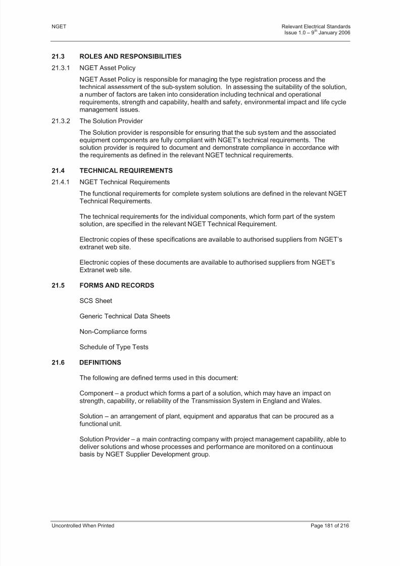
8/3/2019 1 Relevant Standards for Substation Plants
http://slidepdf.com/reader/full/1-relevant-standards-for-substation-plants 188/223
NGET Relevant Electrical StandardsIssue 1.0 – 9
thJanuary 2006
Uncontrolled When Printed Page 181 of 216
21.3 ROLES AND RESPONSIBILITIES
21.3.1 NGET Asset Policy
NGET Asset Policy is responsible for managing the type registration process and thetechnical assessment of the sub-system solution. In assessing the suitability of the solution,
a number of factors are taken into consideration including technical and operationalrequirements, strength and capability, health and safety, environmental impact and life cyclemanagement issues.
21.3.2 The Solution Provider
The Solution provider is responsible for ensuring that the sub system and the associatedequipment components are fully compliant with NGET’s technical requirements. Thesolution provider is required to document and demonstrate compliance in accordance withthe requirements as defined in the relevant NGET technical requirements.
21.4 TECHNICAL REQUIREMENTS
21.4.1 NGET Technical Requirements
The functional requirements for complete system solutions are defined in the relevant NGETTechnical Requirements.
The technical requirements for the individual components, which form part of the systemsolution, are specified in the relevant NGET Technical Requirement.
Electronic copies of these specifications are available to authorised suppliers from NGET’sextranet web site.
Electronic copies of these documents are available to authorised suppliers from NGET’sExtranet web site.
21.5 FORMS AND RECORDS
SCS Sheet
Generic Technical Data Sheets
Non-Compliance forms
Schedule of Type Tests
21.6 DEFINITIONS
The following are defined terms used in this document:
Component – a product which forms a part of a solution, which may have an impact onstrength, capability, or reliability of the Transmission System in England and Wales.
Solution – an arrangement of plant, equipment and apparatus that can be procured as afunctional unit.
Solution Provider – a main contracting company with project management capability, able todeliver solutions and whose processes and performance are monitored on a continuousbasis by NGET Supplier Development group.

8/3/2019 1 Relevant Standards for Substation Plants
http://slidepdf.com/reader/full/1-relevant-standards-for-substation-plants 189/223
NGET Relevant Electrical StandardsIssue 1.0 – 9
thJanuary 2006
Uncontrolled When Printed Page 182 of 216
Self Certification Statement – a documented statement provided by solution providers andcomponent suppliers declaring that the solution and the components comprising thatsolution, satisfies the requirements of the relevant NGET technical requirements and issuitable for the applications for which it is to be supplied.
Asset Code – a unique identifier assigned by NGET for a particular solution and/or component.
Authorised Supplier – a contractor who has qualified for inclusion on NGET’s Vendor Qualification System.
Generic Equipment Model (GEM) - a data set expressing NGET’s User requirements for interfacing to a solution (plant, system or equipment). Specifically it defines the I/O interfacerequirements of a Substation Automation System (Controls, Indications, Alarms, Analoguemeasurements and Information) for any given type of solution, which can be used for monitoring and control purposes. It also details a rationalised data set to be presented atcontrol centres to enable operational control to be managed.
21.7 NOTES
This guidance document supports the User Policy Statements contained in these RelevantElectrical Standards.
21.8 GUIDANCE NOTE - DESIGN DATA PACK
(This Guidance Note does not form part of the RES document)
21.8.1 Document Requirements
a) Technical description of design
b) Layout and or arrangement drawings
c) Calculcations where applicable
d) Site commissioning instructions and test schedules
e) Operation, installation, maintenance, decommissioning and disposal instructions
21.9 GUIDANCE NOTE - STANDARD OF DRAWINGS AND MANUALS
(This Guidance Note does not form part of the RES document)
21.9.1 General Requirements
The requirements set out herein relate to drawings and manuals submitted to NGET bySolution Providers.
Specific drawing requirements for overhead line conductor fittings, insulator fittings, busbar,busbar connectors, and associated fittings for installation on NGET overhead lines andsubstations or for direct connection to NGET’s system are defined in the relevant NGETTechnical Requirements.
All drawings and manuals should be in English and must be submitted electronically or on a
CD-ROM.
8/3/2019 1 Relevant Standards for Substation Plants
http://slidepdf.com/reader/full/1-relevant-standards-for-substation-plants 190/223

8/3/2019 1 Relevant Standards for Substation Plants
http://slidepdf.com/reader/full/1-relevant-standards-for-substation-plants 191/223
NGET Relevant Electrical StandardsIssue 1.0 – 9
thJanuary 2006
Uncontrolled When Printed Page 184 of 216
22 SECTION 2 - WORKING IN PROXIMITY TO LIVE CONDUCTORS -REDUCING THERISKS
22.1 PURPOSE AND SCOPE
These guidelines have been prepared for information and may be used by designers as anindication of designs that will be considered acceptable by NGET. Following theseguidelines does not, however, absolve the designers of their responsibilities for their designunder CDM regulations.
22.2 GENERAL
Designers are obliged to comply with all relevant health and safety legislation, particularlythe designers’ duties under the Construction (Design and Management) Regulations 1994(CDM). In applying the principles of prevention and protection to the reduction of risk,designers’ considerations should include the hazards of working in proximity to exposed liveHV conductors (including 'oversailing' conductors) during construction, operation,maintenance, repair, replacement or demolition of electrical/mechanical equipment and civil
structures.
If the designer does not eliminate hazards presented by exposed live HV conductors fromthe design, there is an obligation on the designer to show, by risk assessment, that thedesign has complied with the principles of prevention and protection, as required by CDM, insome other way. The following hierarchy of risk control shall be considered when selectingalternative control measures.
The preferred hierarchy of risk control principles are:
Eliminate risk altogether
Substitute equipment or activities with less hazardous ones
Combat risk at source by engineering control measures
Reduce risk by suitable safe systems of work
Minimise risk by the use of Personal Protective Equipment.
[Reference NGET National Health & Safety Standard NS-MP1]
22.3 DESIGN PRINCIPLES
It is essential that the Safety Distances (specified in NGET’s Safety Rules Handbook) toexposed live HV conductors are not infringed either deliberately or accidentally during anywork activity. In order to achieve this, designers will need to establish appropriate minimumdesign clearances. These must take into account not only the immediate requirements of the work activity but also additional factors relating to the means of access and workingmethods. An indicative, but not exhaustive, list of factors to be considered when consideringwhether clearances are sufficient include the possibility of a Mobile Elevated Work Platform(MEWP) running out of control, passage of cranes through substations, the use and handlingof scaffold poles and setting up enclosures over cable sealing ends.
The clearances recommended in these guidelines may not, in some circumstances, besufficient to adequately mitigate hazards and designers must be prepared to use riskassessment principles to test their design decisions.
Designers must take account of relevant UK legislation, NGET Safety Rules and relevantTechnical Requirements when considering methods of performing work activities. Theprocedures defined in NGET’s Safety Rules must also be considered (although other
procedures that meet the legal/Safety Rule requirements may be accepted at the discretionof NGET).

8/3/2019 1 Relevant Standards for Substation Plants
http://slidepdf.com/reader/full/1-relevant-standards-for-substation-plants 192/223
NGET Relevant Electrical StandardsIssue 1.0 – 9
thJanuary 2006
Uncontrolled When Printed Page 185 of 216
It is NGET policy to eliminate from new substation construction:
a) Oversailing conductors (as far as is reasonably practicable).
b) Conductors in proximity.
c) Situations where work activities must be carried out above exposed HV conductorsthat are live.
In assessing what is reasonably practicable, designers may wish to use the ALARP (As LowAs Reasonably Practicable) principle outlined in NGET National Health & Safety StandardNS-MP1 and ‘Tolerability of Risk From Nuclear Power Stations’, (HSE Books, 1992).
A higher priority should be placed on eliminating oversailing conductors from routine workactivities than from non-routine work activities. Furthermore, a higher priority should beplaced on eliminating oversailing conductors where access is intended to be by MEWP(where there is a significant risk of accidentally moving out of the operating area as a resultof misjudgement or mechanical failure) than from where access is by temporary fixed-heightplatform.
Note: The specification by the designer of a temporary fixed-height platform in place of aMEWP will not always be acceptable to NGET. Refer to 22.8 for applicationlimitations.
Practically, it is impossible to eliminate exposed live HV conductors from a substation duringwork (with the exception of GIS substations). Part 4, Section 2 of these Relevant ElectricalStandards specifies the following maximum outage conditions:
When considering clearances from roadways to exposed live conductors for vehicle access,designers must take into account the largest load that may reasonably foreseeably need tobe moved on that roadway. The designer shall also identify the proposed access/egress
route for the replacement of the largest single unit of equipment installed on site (e.g.transformer or quadrature booster) taking into account all substation voltages crossing thatroute.
Where a transformer has failed, this will already have resulted in depletion of one circuit at asubstation. It would not, therefore, be an acceptable design solution to require further circuits to be switched out to provide clearance for transporting the failed or replacementunits across site.
Guidance for designers can be categorised according to the nature of the work activity andthe type of access intended by the designer. This guidance is summarised in the table in22.8
22.4 DESIGN GUIDANCE FOR ACCESS FROM GROUND LEVEL OR PERMANENTPLATFORM
The design objective is to allow personnel to move freely around the substation at groundlevel and to safely use:
a) any permanently installed access platforms, or
b) mobile steps which have been specifically designed to access specific plant or equipment whilst live.
Conductors in proximity to any reasonably foreseeable work area shall be eliminated byensuring that the appropriate design clearance for safety DS (as specified in Table 35) has
been achieved from all exposed live conductors.
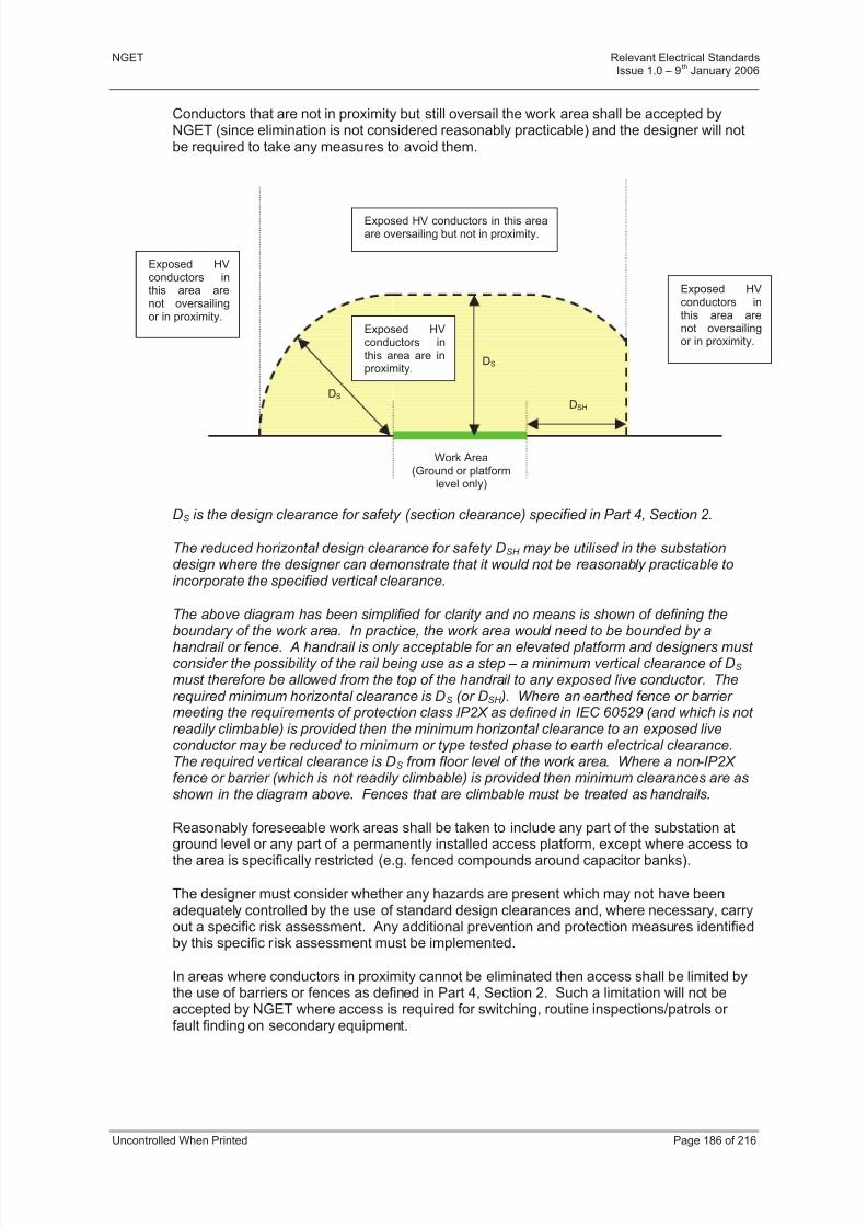
8/3/2019 1 Relevant Standards for Substation Plants
http://slidepdf.com/reader/full/1-relevant-standards-for-substation-plants 193/223
NGET Relevant Electrical StandardsIssue 1.0 – 9
thJanuary 2006
Uncontrolled When Printed Page 186 of 216
Conductors that are not in proximity but still oversail the work area shall be accepted byNGET (since elimination is not considered reasonably practicable) and the designer will notbe required to take any measures to avoid them.
DS is the design clearance for safety (section clearance) specified in Part 4, Section 2.
The reduced horizontal design clearance for safety DSH may be utilised in the substationdesign where the designer can demonstrate that it would not be reasonably practicable toincorporate the specified vertical clearance.
The above diagram has been simplified for clarity and no means is shown of defining the
boundary of the work area. In practice, the work area would need to be bounded by ahandrail or fence. A handrail is only acceptable for an elevated platform and designers must consider the possibility of the rail being use as a step – a minimum vertical clearance of DS must therefore be allowed from the top of the handrail to any exposed live conductor. Therequired minimum horizontal clearance is DS (or DSH ). Where an earthed fence or barrier meeting the requirements of protection class IP2X as defined in IEC 60529 (and which is not readily climbable) is provided then the minimum horizontal clearance to an exposed liveconductor may be reduced to minimum or type tested phase to earth electrical clearance.The required vertical clearance is DS from floor level of the work area. Where a non-IP2X fence or barrier (which is not readily climbable) is provided then minimum clearances are asshown in the diagram above. Fences that are climbable must be treated as handrails.
Reasonably foreseeable work areas shall be taken to include any part of the substation at
ground level or any part of a permanently installed access platform, except where access tothe area is specifically restricted (e.g. fenced compounds around capacitor banks).
The designer must consider whether any hazards are present which may not have beenadequately controlled by the use of standard design clearances and, where necessary, carryout a specific risk assessment. Any additional prevention and protection measures identifiedby this specific risk assessment must be implemented.
In areas where conductors in proximity cannot be eliminated then access shall be limited bythe use of barriers or fences as defined in Part 4, Section 2. Such a limitation will not beaccepted by NGET where access is required for switching, routine inspections/patrols or fault finding on secondary equipment.
DS
DSH
Work Area(Ground or platform
level only)
Exposed HVconductors inthis area are inproximity.
Exposed HV conductors in this areaare oversailing but not in proximity.
Exposed HVconductors inthis area arenot oversailingor in proximity.
Exposed HVconductors inthis area arenot oversailingor in proximity.
DS
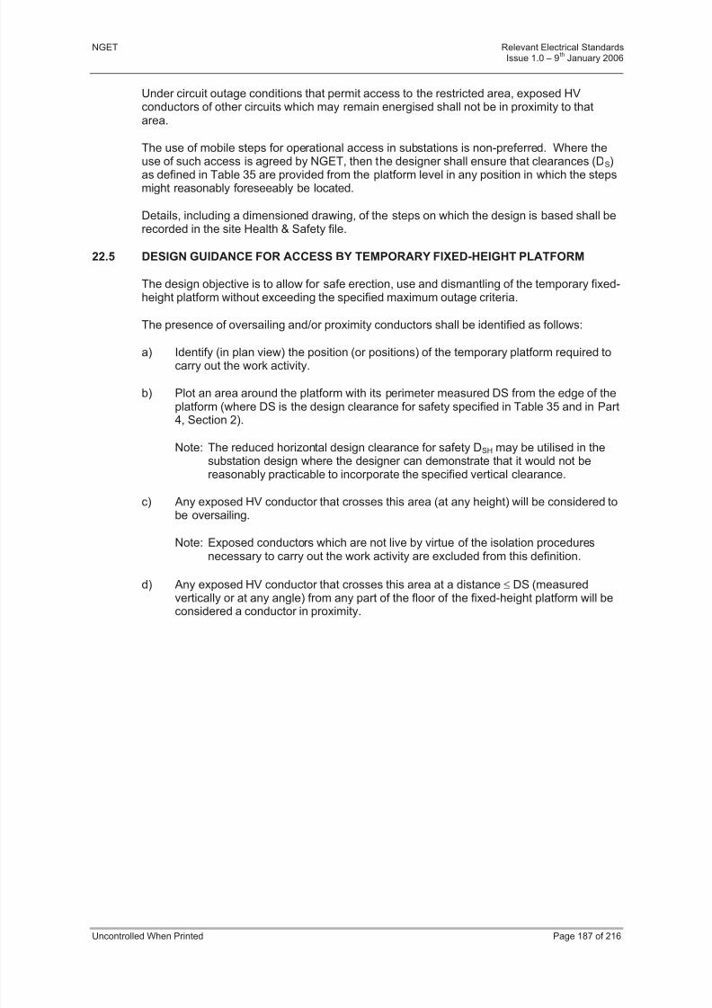
8/3/2019 1 Relevant Standards for Substation Plants
http://slidepdf.com/reader/full/1-relevant-standards-for-substation-plants 194/223
NGET Relevant Electrical StandardsIssue 1.0 – 9
thJanuary 2006
Uncontrolled When Printed Page 187 of 216
Under circuit outage conditions that permit access to the restricted area, exposed HVconductors of other circuits which may remain energised shall not be in proximity to thatarea.
The use of mobile steps for operational access in substations is non-preferred. Where theuse of such access is agreed by NGET, then the designer shall ensure that clearances (DS)
as defined in Table 35 are provided from the platform level in any position in which the stepsmight reasonably foreseeably be located.
Details, including a dimensioned drawing, of the steps on which the design is based shall berecorded in the site Health & Safety file.
22.5 DESIGN GUIDANCE FOR ACCESS BY TEMPORARY FIXED-HEIGHT PLATFORM
The design objective is to allow for safe erection, use and dismantling of the temporary fixed-height platform without exceeding the specified maximum outage criteria.
The presence of oversailing and/or proximity conductors shall be identified as follows:
a) Identify (in plan view) the position (or positions) of the temporary platform required tocarry out the work activity.
b) Plot an area around the platform with its perimeter measured DS from the edge of theplatform (where DS is the design clearance for safety specified in Table 35 and in Part4, Section 2).
Note: The reduced horizontal design clearance for safety DSH may be utilised in thesubstation design where the designer can demonstrate that it would not bereasonably practicable to incorporate the specified vertical clearance.
c) Any exposed HV conductor that crosses this area (at any height) will be considered to
be oversailing.
Note: Exposed conductors which are not live by virtue of the isolation proceduresnecessary to carry out the work activity are excluded from this definition.
d) Any exposed HV conductor that crosses this area at a distance DS (measuredvertically or at any angle) from any part of the floor of the fixed-height platform will beconsidered a conductor in proximity.
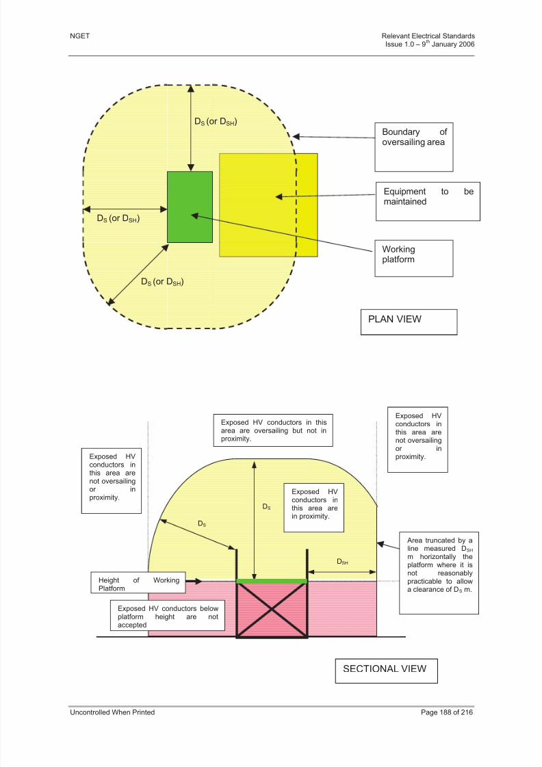
8/3/2019 1 Relevant Standards for Substation Plants
http://slidepdf.com/reader/full/1-relevant-standards-for-substation-plants 195/223
NGET Relevant Electrical StandardsIssue 1.0 – 9
thJanuary 2006
Uncontrolled When Printed Page 188 of 216
Equipment to bemaintained
Working
platform
Boundary of oversailing area
DS (or DSH)
PLAN VIEW
DS (or DSH)
DS (or DSH)
DS
DS
Exposed HVconductors inthis area arein proximity.
Exposed HV conductors in thisarea are oversailing but not inproximity.
Exposed HVconductors inthis area arenot oversailingor inproximity.
Exposed HVconductors inthis area arenot oversailingor inproximity.
Exposed HV conductors belowplatform height are notaccepted
SECTIONAL VIEW
DSH
Height of WorkingPlatform
Area truncated by aline measured DSH
m horizontally theplatform where it isnot reasonablypracticable to allowa clearance of DS m.

8/3/2019 1 Relevant Standards for Substation Plants
http://slidepdf.com/reader/full/1-relevant-standards-for-substation-plants 196/223
NGET Relevant Electrical StandardsIssue 1.0 – 9
thJanuary 2006
Uncontrolled When Printed Page 189 of 216
The diagrams above have been simplified for clarity. When preparing designs, designersmust consider the possibility of the platform handrail being use as a step. Unless alternativecontrol measures are proposed a minimum vertical clearance of DS must thus be allowed from the top of the handrail to any exposed live conductor .
The designer must consider whether any hazards are present which may not have beenadequately controlled by the use of standard design clearances and, where necessary, carryout a specific risk assessment. Any additional prevention and protection measures identifiedby this specific risk assessment must be implemented.
Additional risks to be considered might be erection of temporary platforms and, whereapplicable, handling long objects such as scaffold poles. Possible variations in the locationof the temporary platform must also be considered.
Where a design does not eliminate oversailing conductors, this may still be acceptable. Inthese cases the designer will be required to demonstrate:
a) That the conductors are not in proximity, and
b) That it is not reasonably practicable to eliminate the oversailing condition or to further increase the clearance from the working platform.
c) That a suitable and sufficient risk assessment of the design has been documentedand implemented.
Where designers intend temporary fixed-height platforms to be used for fault investigation of secondary equipment or routine maintenance then details shall be included in the site Health& Safety file of the height, size and location of the platform on which the design is basedtogether with any special requirements for erection or dismantling.
The Health & Safety file must also contain details of access arrangements for reasonably
foreseeable non-routine work activities (e.g. repair/replacement of major substationcomponents) where the access requirements are critical to the substation design. Thesedetails must include requirements for additional circuit outages beyond those that would beassumed from the electrical diagram of the substation.
22.6 DESIGN GUIDANCE FOR ACCESS BY MEWP
The design objective is to allow for safe use of a MEWP without exceeding the specifiedmaximum outage criteria. Because of the risk of misjudgement or mechanical failure, NGETconsider it necessary to provide an additional design margin when allowing clearances for use of a MEWP. As a minimum, designers must ensure that their design does not requireany part of the MEWP or of the operator’s body to infringe the ‘vicinity zone’ (as defined inBS EN 50110) surrounding exposed HV conductors which remain energised during the work
activity.
Designers should note that the minimum clearances to exposed live conductors suggested inthese guidelines provide a margin to allow for misjudgement or mechanical failure.
22.6.1 The presence of oversailing/proximity conductors shall be identified as follows:
a) Identify (in plan view) the area that will be traversed by the platform of the MEWPduring the work activity. Also identify the area occupied by the MEWP base unit andthat area which will be traversed by any overhanging parts of the MEWP (e.g.booms). Together, these areas form the MEWP operating area.
b) Plot an additional area around the MEWP operating area with its perimeter measuredDA from the edge of the area (where DA is the horizontal design clearance for safetyspecified in Specific Requirements Section + 2 m).

8/3/2019 1 Relevant Standards for Substation Plants
http://slidepdf.com/reader/full/1-relevant-standards-for-substation-plants 197/223
NGET Relevant Electrical StandardsIssue 1.0 – 9
thJanuary 2006
Uncontrolled When Printed Page 190 of 216
Note: DA incorporates safety distance + personal reach + 2 m margin and thusexceeds the vicinity zone perimeter clearance DV suggested in some other documents such as draft IEC 61936.
c) Any exposed HV conductor that crosses this area (at any height) will be considered tobe oversailing.
Note: Exposed conductors which are not live by virtue of the isolation proceduresnecessary to carry out the work activity are excluded from this definition.
d) The vertical dimension of the MEWP operating area will be determined by themaximum height that the base of the MEWP platform is required to reach to carry outthe work activity. Unless otherwise defined, this height will be taken to be themaximum height of the equipment being maintained.
e) Any exposed HV conductor that crosses the zone at a distance DB (measuredvertically or at any angle) from any part of the MEWP operating area will generally beconsidered a conductor in proximity, (where DB is the vertical design clearance for safety specified in Specific Requirements Section + 2 m).
Note: In some cases it may be acceptable to consider different platform operatingheights in parts of the MEWP operating area (e.g. the area traversed byoverhanging parts of the MEWP). Designers using this approach must,however, demonstrate that it is not reasonably practicable to design on thebasis of a uniform worst-case MEWP operating area height.
Note: It is not generally necessary to take account of the possibility of staff climbingon the handrail of the MEWP platform. The 2 m margin is considered adequateto manage this risk since it is considered unlikely that personnel will climb onthe handrail whilst the platform is in motion.

8/3/2019 1 Relevant Standards for Substation Plants
http://slidepdf.com/reader/full/1-relevant-standards-for-substation-plants 198/223
NGET Relevant Electrical StandardsIssue 1.0 – 9
thJanuary 2006
Uncontrolled When Printed Page 191 of 216
DA
DB
DB
Exposed HV conductors inthis area are oversailin but
Exposed HVconductors inthis area arenot oversailingor in proximity.
Exposed HVconductors inthis area arenot oversailingor in proximity.
Exposed HVconductorsin this area
MEWPoperatingarea
PLAN VIEW
DA
DA
DA
Boundary of oversailing area
MEWP baseunit
Area traversed byMEWP platform
Area traversed by MEWPoverhanging parts
Boundary of MEWPoperating area

8/3/2019 1 Relevant Standards for Substation Plants
http://slidepdf.com/reader/full/1-relevant-standards-for-substation-plants 199/223
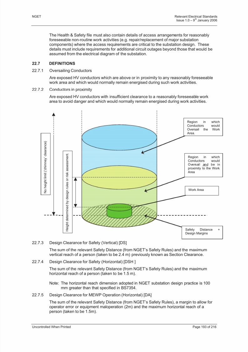
8/3/2019 1 Relevant Standards for Substation Plants
http://slidepdf.com/reader/full/1-relevant-standards-for-substation-plants 200/223
NGET Relevant Electrical StandardsIssue 1.0 – 9
thJanuary 2006
Uncontrolled When Printed Page 193 of 216
The Health & Safety file must also contain details of access arrangements for reasonablyforeseeable non-routine work activities (e.g. repair/replacement of major substationcomponents) where the access requirements are critical to the substation design. Thesedetails must include requirements for additional circuit outages beyond those that would beassumed from the electrical diagram of the substation.
22.7 DEFINITIONS
22.7.1 Oversailing Conductors
Are exposed HV conductors which are above or in proximity to any reasonably foreseeablework area and which would normally remain energised during such work activities.
22.7.2 Conductors in proximity
Are exposed HV conductors with insufficient clearance to a reasonably foreseeable workarea to avoid danger and which would normally remain energised during work activities.
22.7.3 Design Clearance for Safety (Vertical) [DS]
The sum of the relevant Safety Distance (from NGET’s Safety Rules) and the maximumvertical reach of a person (taken to be 2.4 m) previously known as Section Clearance.
22.7.4 Design Clearance for Safety (Horizontal) [DSH ]
The sum of the relevant Safety Distance (from NGET’s Safety Rules) and the maximumhorizontal reach of a person (taken to be 1.5 m).
Note: The horizontal reach dimension adopted in NGET substation design practice is 100mm greater than that specified in BS7354.
22.7.5 Design Clearance for MEWP Operation (Horizontal) [DA]
The sum of the relevant Safety Distance (from NGET’s Safety Rules), a margin to allow for operator error or equipment maloperation (2m) and the maximum horizontal reach of aperson (taken to be 1.5m).
Safety Distance +Design Margins
Region in whichConductors wouldOversail and be inproximity to the WorkArea
Region in whichConductors wouldOversail the WorkArea.
Work Area
H e i g h t d e t e r m i n e d b y d e s i g n r u l e s o r r i s k a s s e s s m e n t .
N o h e i g h
t l i m i t ( ‘ c h i m n e y ’ c l e a r a n c e )

8/3/2019 1 Relevant Standards for Substation Plants
http://slidepdf.com/reader/full/1-relevant-standards-for-substation-plants 201/223
NGET Relevant Electrical StandardsIssue 1.0 – 9
thJanuary 2006
Uncontrolled When Printed Page 194 of 216
Note: The Safety Distance + 2 m margin, when measured from an exposed live conductor,defines the boundary of the Vicinity Zone (as specified in BS EN 50110). The designphilosophy is that neither the MEWP, any part of the operators body or any object heldby the operator should infringe the Vicinity Zone.
22.7.6 Design Clearance for MEWP Operation (Vertical) [DB]
The sum of the relevant Safety Distance (from NGET’s Safety Rules), a margin to allow for operator error or equipment maloperation (2 m) and the maximum vertical reach of a person(taken to be 2.4 m).
Values of DA, DB, DS and DSH for NGET system voltages are tabulated in Table 35 below.
Nominal System Voltage(kV)
11/22/33 66 132 275 400
NG Safety Rules, SafetyDistance
0.8 1.0 1.4 2.4 3.1
Design Clearance for Safety(Vertical) [DS]
3.2 3.4 3.8 4.8 5.5
Design Clearance for Safety(Horizontal) [DSH]
2.3 2.5 2.9 3.9 4.6
Design Clearance for MEWPOperation (Vertical [DB]
5.2 5.4 5.8 6.8 7.5
Design Clearance for MEWPOperation (Horizontal) [DA]
4.3 4.5 4.9 5.9 6.6
Minimum Height of ConductorsAbove Roadways **
5.8 6.0 6.7 7.0 7.3
Table 35 - Values of minimum clearances (mtrs) for NGET system voltages
**Informative: Values given above are based upon the Electricity Safety, Quality & Continuity Regulations 2002. Part 4, Section 2 of these Relevant Electrical Standards also permits avalue based upon the maximum vehicle height + 0.5m + safety distance. Actual values to beused shall be the greater of the two values.
22.7.7 Non-Primary System Work
Any work in a substation which is not directly associated with equipment forming part of NGET’s system.
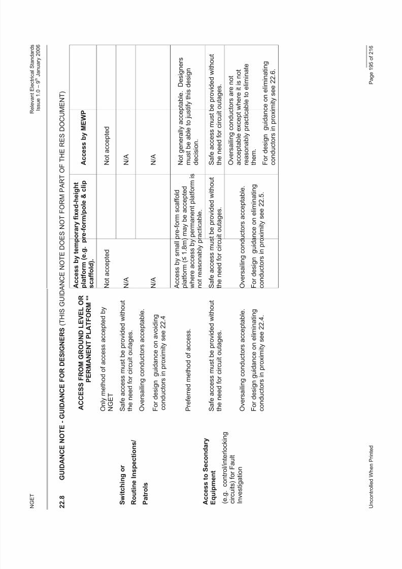
8/3/2019 1 Relevant Standards for Substation Plants
http://slidepdf.com/reader/full/1-relevant-standards-for-substation-plants 202/223
N G E T
R e l e v a n t E l e c t r i c a l S t a n d a r d s
I s s u e 1 . 0 – 9 t h J a n u a r y 2 0 0 6
U n c o n t r o
l l e d W h e n P r i n t e d
P a g e 1 9 5 o f 2 1 6
2 2 . 8
G U I D A N C E N O T E - G U I D A N C
E F O R D E S I G N E R S ( T H I S G U I D
A N C E N O T E D O E S N O T F O R M
P A R T O F T H E R E S D O C U M E N T )
A C C E S S F R O M G R O U N D L E V E L O R
P E R M A N E N T P L A T F O R M * *
A c c e s s b y t e m p o r a r y f i x e d - h e i g h t
p l a t f o r m ( e . g . p r e - f o r m / p o l e &
c l i p
s c a f f o l d ) .
A c c e s s b y M E W P
O n l y m e t h o d o f a c c e s s a c c e p t e d b y
N G E T
N o t a c c e p t e d
N o t a c c e p t e d
S a f e a c
c e s s m u s t b e p r o v i d e d w i t h o u t
t h e n e e
d f o r c i r c u i t o u t a g e s .
N / A
N / A
S w i t c
h i n g o r
R o u t i n e I n s p e c t i o n s /
P a t r o
l s
O v e r s a i l i n g c o n d u c t o r s a c c e p t a b l e .
F o r d e s
i g n g u i d a n c e o n a v o i d i n g
c o n d u c
t o r s i n p r o x i m i t y s e e 2 2 . 4
N / A
N / A
P r e f e r r e d m e t h o d o f a c c e s s .
A c c e s s b y s m a l l p r e - f o r m s c a f f o l d
p l a t f o r m ( 1 . 8 m ) m a y b e a c c e p t e d
w h e r e a c c e s s b y p e r m a n e n t p l a t f o r m i s
n o t r e a s o n a b l y p r a c t i c a b l e .
N o t g e n e r a l l y a c c e p t a b l e . D e s i g n e r s
m u s t b e a b l e t o j u s t i f y t h
i s d e s i g n
d e c i s i o n .
S a f e a c
c e s s m u s t b e p r o v i d e d w i t h o u t
t h e n e e
d f o r c i r c u i t o u t a g e s .
S a f e a c c e s s m u s t b e p r o v i d e d w
i t h o u t
t h e n e e d f o r c i r c u i t o u t a g e s .
S a f e a c c e s s m u s t b e p r o v i d e d w i t h o u t
t h e n e e d f o r c i r c u i t o u t a g e s .
A c c e s s t o S e c o n d a r y
E q u i p
m e n t
( e . g .
c o n t r o l / i n t e r l o c k i n g
c i r c u i t s ) f o r F a u l t
I n v e s t i g a t i o n
O v e r s a i l i n g c o n d u c t o r s a c c e p t a b l e .
F o r d e s
i g n g u i d a n c e o n e l i m i n a t i n g
c o n d u c t o r s i n p r o x i m i t y s e e 2 2 . 4 .
O v e r s a i l i n g c o n d u c t o r s a c c e p t a b
l e .
F o r d e s i g n g u i d a n c e o n e l i m i n a t i n g
c o n d u c t o r s i n p r o x i m i t y s e e 2 2 . 5
.
O v e r s a i l i n g c o n d u c t o r s a r e n o t
a c c e p t a b l e e x c e p t w h e r
e i t i s n o t
r e a s o n a b l y p r a c t i c a b l e t o e l i m i n a t e
t h e m .
F o r d e s i g n g u i d a n c e o n
e l i m i n a t i n g
c o n d u c t o r s i n p r o x i m i t y s e e 2 2 . 6 .

8/3/2019 1 Relevant Standards for Substation Plants
http://slidepdf.com/reader/full/1-relevant-standards-for-substation-plants 203/223
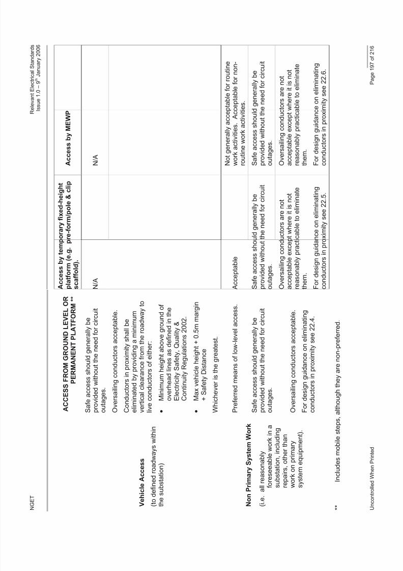
8/3/2019 1 Relevant Standards for Substation Plants
http://slidepdf.com/reader/full/1-relevant-standards-for-substation-plants 204/223
N G E T
R e l e v a n t E l e c t r i c a l S t a n d a r d s
I s s u e 1 . 0 – 9 t h J a n u a r y 2 0 0 6
U n c o n t r o
l l e d W h e n P r i n t e d
P a g e 1 9 7 o f 2 1 6
A C C E S S F R O M G R O U N D L E V E L O R
P E R M A N E N T P L A T F O R M * *
A c c e s s b y t e m p o r a r y f i x e d - h e i g h t
p l a t f o r m ( e . g . p r e - f o r m / p o l e &
c l i p
s c a f f o l d ) .
A c c e s s b y M E W P
S a f e a c
c e s s s h o u l d g e n e r a l l y b e
p r o v i d e
d w i t h o u t t h e n e e d f o r c i r c u i t
o u t a g e s .
N / A
N / A
V e h i c
l e A c c e s s
( t o d e f i n e d r o a d w a y s w i t h i n
t h e s u
b s t a t i o n )
O v e r s a i l i n g c o n d u c t o r s a c c e p t a b l e .
C o n d u c
t o r s i n p r o x i m i t y s h a l l b e
e l i m i n a t e d b y p r o v i d i n g a m i n i m u m
v e r t i c a l
c l e a r a n c e f r o m t h e r o a d w a y t o
l i v e c o n
d u c t o r s o f e i t h e r :
M i n
i m u m h e i g h t a b o v e g r o u n d o f
o v e
r h e a d l i n e s a s d e f i n e d i n t h e
E l e c t r i c i t y S a f e t y , Q u a l i t y &
C o n t i n u i t y R e g u l a t i o n s 2 0 0 2 .
M a x v e h i c l e h e i g h t + 0 . 5 m m a r g i n
+ S
a f e t y D i s t a n c e
W h i c h e
v e r i s t h e g r e a t e s t .
P r e f e r r e d m e a n s o f l o w - l e v e l a c c e s s .
A c c e p t a b l e
N o t g e n e r a l l y a c c e p t a b l e f o r r o u t i n e
w o r k a c t i v i t i e s . A c c e p t a
b l e f o r n o n -
r o u t i n e w o r k a c t i v i t i e s .
S a f e a c
c e s s s h o u l d g e n e r a l l y b e
p r o v i d e
d w i t h o u t t h e n e e d f o r c i r c u i t
o u t a g e s .
S a f e a c c e s s s h o u l d g e n e r a l l y b e
p r o v i d e d w i t h o u t t h e n e e d f o r c i r c u i t
o u t a g e s .
S a f e a c c e s s s h o u l d g e n
e r a l l y b e
p r o v i d e d w i t h o u t t h e n e e d f o r c i r c u i t
o u t a g e s .
N o n P
r i m a r y S y s t e m W o r k
( i . e . a
l l r e a s o n a b l y
f o r e s e e a b l e w o r k i n a
s u b s t a t i o n , i n c l u d i n g
r e p a i r s , o t h e r t h a n
w o r k o n p r i m a r y
s y s t e m e q u i p m e n t ) .
O v e r s a i l i n g c o n d u c t o r s a c c e p t a b l e .
F o r d e s
i g n g u i d a n c e o n e l i m i n a t i n g
c o n d u c t o r s i n p r o x i m i t y s e e 2 2 . 4 .
O v e r s a i l i n g c o n d u c t o r s a r e n o t
a c c e p t a b l e e x c e p t w h e r e i t i s n o t
r e a s o n a b l y p r a c t i c a b l e t o e l i m i n a
t e
t h e m .
F o r d e s i g n g u i d a n c e o n e l i m i n a t i n g
c o n d u c t o r s i n p r o x i m i t y s e e 2 2 . 5
.
O v e r s a i l i n g c o n d u c t o r s a r e n o t
a c c e p t a b l e e x c e p t w h e r
e i t i s n o t
r e a s o n a b l y p r a c t i c a b l e t o e l i m i n a t e
t h e m .
F o r d e s i g n g u i d a n c e o n
e l i m i n a t i n g
c o n d u c t o r s i n p r o x i m i t y s e e 2 2 . 6 .
* *
I n c l u d e s m o b i l e s t e p s , a l t h o u g h
t h e y a r e n o n - p r e f e r r e d .
8/3/2019 1 Relevant Standards for Substation Plants
http://slidepdf.com/reader/full/1-relevant-standards-for-substation-plants 205/223
NGET Relevant Electrical StandardsIssue 1.0 – 9
thJanuary 2006
Uncontrolled When Printed Page 198 of 216
23 SECTION 3 - CONDUCTOR JOINTING IN SUBSTATIONS
23.1 PURPOSE AND SCOPE
Within a substation there are many electrical connections ranging from high current busbar
and earthing joints down to small assemblies on electronic circuit boards. This appendixdeals with the former i.e. connections required to carry either primary load current or faultcurrent or both. The associated maximum permitted temperatures under these conditions
are 90C and 405C (325C for aluminium). This appendix does not cover equipmentcontacts, contractors, and sliding/moving contacts for which specific and detailed installationand maintenance instructions exist.
The integrity of busbar and earthing connections is essential for the security and safety of the high voltage substation. They are heavily loaded and temperatures at the connectioninterface are high such that degradation of poorly made and maintained joints is likely.Outdoor connections that operate under all weather conditions require protection to avoidcorrosion induced long-term degradation.
The aim of this document is to provide guidance on good practice for conductor jointing insubstations and it is Informative rather than Normative in nature. It aims to promote a goodunderstanding of how to achieve high quality electrical connection and details typicalproblems encountered within the jointing process. Particular emphasis is placed on bolted joints for two reasons. Firstly, they can be less secure than joints which rely on fusion of materials e.g. welding and secondly, many bolted joints are disconnected for maintenance or to provide electrical isolation and thereby are at risk of being incorrectly remade.
23.2 JOINTING GUIDELINES
There are a wide range of jointing methods available but, without exception, their effectiveness relies on trained people working to established procedures. Inadequatelytrained workers or a disregard of the precise instructions is liable to be unsafe and result in
an inadequate connection.
Guidance Notes 23.11 and 23.12 provide a summary of different joint types, their applicationsuitability and appropriate standards that may apply. Where particular jointing instructionsexist, they should be followed, since they will normally have been developed and tested bythe manufacturer or supplier.
23.3 BOLTED JOINTS
23.3.1 Preparation of Unplated/Untinned Bare Surfaces of Bolted Joints
Brushing using a stainless steel wire brush is widely used to remove gross oxide films andcontamination and to create the rough sharp peaks needed for good electrical contact.
However, the ends of the steel tines become rounded after repeated use and the brush thenloses its effectiveness. A more reliable method of abrasion is to use aluminium oxide clothgrade 80. Aluminium surfaces require particularly diligent surface preparation.
The following procedure has been found to give consistent low resistance joints.
a) Use a suitable solvent to clean dirty or greasy surfaces such as Elecsol 41 or ElecsolSuper which may be obtained from Forward Chemicals Ltd, Tel 0151 4249441
b) Remove any burrs around bolt-holes or edges. Busbar or strip should be flat and anynoticeable bowing or distortion should be removed.
c) Use a fresh strip of aluminium oxide cloth Grade 80 and thoroughly abrade the matingsurfaces.

8/3/2019 1 Relevant Standards for Substation Plants
http://slidepdf.com/reader/full/1-relevant-standards-for-substation-plants 206/223
NGET Relevant Electrical StandardsIssue 1.0 – 9
thJanuary 2006
Uncontrolled When Printed Page 199 of 216
d) Without delay, coat each surface with a thin layer of suitable grease for jointing, e.g.Castrol ‘Rustilo 431’ or equivalent.
Certain types of joint combinations can develop instability if operating at continuous hightemperature. For these types of joint, a suitable transition interface should be used asindicated in 23.11. One of the methods of achieving this is by transition washers, which can
be obtained from Sicame Electrical Developments Ltd, Huddersfield, Tel 01484 681115.The assembly instructions provided should be strictly followed.
23.3.2 Preparation of Tinned or Plated Surfaces of Bolted Joints
a) Use a suitable solvent to clean dirty or greasy surfaces such as Elecsol 41 or ElecsolSuper, obtained from Forward Chemicals Ltd Tel 0151 4249441
b) Remove any burrs around bolt-holes or edges. Busbar or strip should be flat and anynoticeable bowing or distortion should be removed.
c) Do not prepare plated surfaces unless they appear badly tarnished. Atoothbrush/nylon nailbrush or similar can be used to remove tarnish without scratchingthe plating. The exception is nickel plating which has a surface film which can inhibitgood contact if the contact pressure is low. It is prudent to abrade this surface lightlyand carefully with grade 400 oxide paper.
d) Without delay, coat each surface with a thin layer of approved grease for jointing, e.g.Castrol ‘Rustilo 431’ or equivalent.
Note The surfaces of bolted joints that are working in transformer oil should be coated withPetroleum Jelly. Other greases may be chemically incompatible.
23.3.3 Assembly of Bolted Joints
a) Ensure that nuts run freely on the bolts or studs.
b) Assemble the joint as soon as possible after the surfaces have been prepared tominimise oxide growth and contamination of the surfaces.
c) Ensure the correct sized washers have been placed under the bolt head and nutbefore tightening.
d) Tighten using a torque wrench set for the size and grade of bolt material.
e) If the electrical connections allow, measure the resistance of the joint and check thevalue is less than the resistance of the same length of un-jointed bar.
f) Protect joints used outdoors against corrosion. Smear a liberal amount of grease e.g.Castrol ‘Rustilo 431’ or equivalent around the joint edges of similar metal joints. If themetals are dissimilar e.g. aluminium bolted to copper, overwrap the whole area of overlap with anticorrosion tape such as Densochrome Tape or preinstall a heat shrinksleeve packed with Castrol ‘Rustilo 431’grease or equivalent. Mastic may be morepracticable for complex shapes.
Note Do not install copper to aluminium connections with the copper above the aluminiumas copper salts can drain down and cause electrolytic action.
8/3/2019 1 Relevant Standards for Substation Plants
http://slidepdf.com/reader/full/1-relevant-standards-for-substation-plants 207/223
NGET Relevant Electrical StandardsIssue 1.0 – 9
thJanuary 2006
Uncontrolled When Printed Page 200 of 216
23.3.4 Service Performance of Bolted Joints
Bolted joints prepared and assembled in accordance with the above recommendationsshould give a long and trouble-free life making continuous monitoring unnecessary.However, joints which carry high continuous or cyclic currents or which experience
mechanical disturbance, vibration or shock may be susceptible to some degradation and aconsequent increase in electrical resistance. Overheating may result.
Measurement of joint temperatures using an infrared camera or measurement of jointresistance can be used to ascertain the condition of current carrying joints. A joint resistancegreater than the resistance of the same length of unjointed conductor is a cause for further investigation and, if possible, a comparison should be made with the resistance of similar joints and with commissioned resistance values.
23.4 OTHER METHODS OF JOINTING
This section briefly describes jointing techniques, other than bolting, with an indication of their effectiveness, security and problems.
23.4.1 Gas Shielded Electric Arc Welding (MIG – TIG)
Welding of copper, aluminium and steel produces efficient and compact joints and is usefulfor jointing tubular conductors and conductors of different cross-sections. Effective jointingrelies on correct procedures being followed (see BS 3571-1 and BS 3019-1) and appropriatetraining (see BS 4872-2 and BS EN 287-2). Particular attention must be paid to the effectivetenting of the work area to ensure a relatively draught free environment. Failure to maintainthis environment can result in the gas shield being broken resulting in porous or oxidisedwelds. Measurement of the resistance of completed joints is unnecessary since theelectrical contact area is relatively large. Sample testing of completed joints should beundertaken in accordance with BS 3451 and BS EN 1320.
23.4.2 Fusion Electric Arc Welding, Gas Brazing and High Temperature Soldering
These techniques are a common and convenient way of joining copper, aluminium andcertain other materials. During fillet or lap jointing of aluminium the fluoride flux used duringthe jointing process is liable to entrapment between contracting metal surfaces. Thismaterial is inherently corrosive and may cause joint deterioration over time despite initialindications of an effective joint. On this basis this technique should be avoided.
Electric arc fusion welding of copper is unsatisfactory due to porosity and brittle inter-metallicformations impairing the mechanical properties of the joint.
Copper/aluminium jointing requires careful control and the provision of a 0.75-1mm layer of silver brazing alloy to the weld area of the copper. This is metallurgically compatible with
both copper and aluminium and jointing can be performed by direct fusion welding usingconventional aluminium-silicon filler metal.
Jointing of copper to rebar steel or wrought iron can be achieved by ‘bronze welding’. Thisrefernce to welding is misleading since there is no melting of the parent metals. A strongbond is created by the flow of the filler metal and the wetting of the parent metals. The filler wire consists of copper rich alloys and has a lower melting point than the parent metals.Joint preparation and cleanliness are essential to ensure that the molten filler metal flowsover the complete joint area. Joint quality is not easy to determine since the electricalresistance will normally be very low. BS EN 1320 recommends the use of a fracture testconducted with dynamic sensible strokes (3 off) applied from a hammer to check whether the joint is sound.
8/3/2019 1 Relevant Standards for Substation Plants
http://slidepdf.com/reader/full/1-relevant-standards-for-substation-plants 208/223
NGET Relevant Electrical StandardsIssue 1.0 – 9
thJanuary 2006
Uncontrolled When Printed Page 201 of 216
23.4.3 Explosive Jointing / Cold Pressure Welding
These techniques are used mainly for joining aluminium-aluminium and copper-copper. Thetechnique bonds material mating faces by compression from either explosive detonation(explosive jointing) or the hydraulic application of localised compressive forces (cold
pressure welding). Cold pressure welding typically employs interconnection by four welddimples. Joints of this type are particularly difficult to maintain since the resistance of theindividual dimples must be measured to ensure the joint integrity.
Experience has shown that aluminium/copper joints of this type suffer from the formation of brittle inter-metallic compounds during the jointing process. Aluminium/aluminium jointssuffer similarly if joint face preparation is inadequate. Joints of this type have been know tofail as a result of a hammer blow and, in extreme cases, with no apparent externalinterference. These methods of jointing are considered unacceptable to NGET.
23.4.4 Eutectic Welding
This technique employs a carbon crucible and an ignitable eutectic mixture surrounding the
area to be joined. Localised heating causes fusion of metal to eutectic. Specialistcompanies market the components for eutectic welding and the precise jointing instructionsmust be followed if a successful joint is to be made. Copper – copper, copper – aluminiumand copper – steel combinations are possible. Joints involving steel require particular carein their preparation. The eutectic that is formed may have a melting point lower than that of the parent metal. Earthing strip joints, for example, which may rise to very hightemperatures during high intensity faults are particularly dependent on the eutecticproperties. The supplier must always be consulted in case of doubt.
A mechanical shock is the only way to check the joint has been satisfactorily fused. Thefinished joint often appears with small blow holes which do not detract from joint efficiencybut the porosity could contribute to corrosive degradation in the longer term. A coating of bitumastic paint will provide protection.
23.4.5 Compression Jointing
This method is applicable to joining solid or circular conductors. It is important that the dies,compression tools and the ferrules or lugs from the same manufacturer. Subject to thisrequirement, the main features are cleaning of the conductor, the correct use of the die (thatis the number and order of compression bites) and applying the correct pressure from thehand or hydraulic tool. Greasing of the conductor may be specified to enhance stability andinhibit corrosion.
Compression jointing of flexible aluminium conductor in a substation requires diligentattention to surface preparation. Manufacturers were faced with considerable difficulties inthe 1970's in designing compression jointing systems for aluminium conductors that were
stable over a thirty year lifespan and many changes to design parameters have been made.Surface preparation and adherence to jointing instructions is equally important today and ameasurement of the electrical resistance after assembly is vital. The resistance of the jointshould be less than the resistance of the same length of conductor however more specificpass/fail figures are often provided by the supplier.
Greasing of outdoor compression joints is especially important. The large compression joints used on down-droppers from an overhead line entry are particularly susceptible toinadequate greasing of the barrel since water can drain down into the joint and set up acorrosive cell.

8/3/2019 1 Relevant Standards for Substation Plants
http://slidepdf.com/reader/full/1-relevant-standards-for-substation-plants 209/223
NGET Relevant Electrical StandardsIssue 1.0 – 9
thJanuary 2006
Uncontrolled When Printed Page 202 of 216
23.5 SURFACES IN CONTACT
23.5.1 Background Information
Metal parts welded together by thermal fusion or brazing are kept in intimate contact by
molecular attraction forces that are a characteristic of all solid materials. They act as onematerial with electricity able to flow without hindrance across the interface. In practice theremay be occlusions and voids which reduce the mechanical strength of the joint. They alsoreduce the area for conducting electricity but there is normally so much redundancy inelectrical contact area that overheating is not a problem.
Metal parts welded together by the action of pressure alone are also held in intimate contactby molecular attraction forces. However, pressure welded joints have significantly less areain mechanical and electrical contact than heat fused joints. Surface oxide films are onlyruptured and they remain within the interface as non-conducting areas which have little or nomechanical bonding strength. Recent experience within NGET is of pressure welds failingduring normal service and also after site checks were conducted by tapping the joints with a‘sensible blow’ from a hammer. Principally these failures have been attributed to
unsatisfactory surface preparation prior to the jointing process. Since this preparation isdifficult to guarantee this method of jointing is presently unacceptable to NGET.
Finally there are purely mechanical joints of bolted or compression type. Bolted joints arecharacterised by the drilling of the mating surfaces and clamping by mean of bolts. These joints are readily disconnectable and are commonly used. Compression joints involve thesliding of a ferrule or tubular lug over a circular or shaped conductor. The two parts are thenforced into intimate contact using a mechanical tool with indenting dies. The hoop stresscreated in the distorted ferrule maintains contact. This connection is commonly used for cable & flexible conductor ends and once made can only be removed by cutting off thecomplete assembly.
23.5.2 Basic Principles
An understanding of the fundamentals of surfaces in contact is important if bolted joints areto be correctly made and maintained.
When two surfaces come together under pressure contact is made where the highest peaksor asperities meet. Even surfaces apparently smooth to the eye are sufficiently rough on amicroscopic scale for the contact to be limited to isolated points. These points are under such high pressure that they deform plastically until sufficient contact area exists to supportthe applied mechanical load. Current flowing across the interface is thus constricted to thesmall areas in contact – see Figure 20.
Figure - 20 - Surfaces in Contact and Current Flow
The electrical resistance of the joint is related to the extent that the surfaces are in contactand measurement of the resistance of the joint is a guide to joint efficiency i.e. how muchelectrical contact has been achieved.

8/3/2019 1 Relevant Standards for Substation Plants
http://slidepdf.com/reader/full/1-relevant-standards-for-substation-plants 210/223
NGET Relevant Electrical StandardsIssue 1.0 – 9
thJanuary 2006
Uncontrolled When Printed Page 203 of 216
The measurement of resistance (V/I) is normally made using a direct reading instrument withthe readout typically in microhms, (µ). Determination of joint efficiency is normally bycomparison of the electrical resistance of the joint with that of the same length of un-jointedbusbar. By reference to Figure 21 it is clear that a perfect joint with an appropriate overlapand contact across the whole surface would have an electrical resistance of about 1/2 that of an unjointed busbar. The “resistance ratio” is 0.5. The aim is for joints made in the
substation, and particularly those carrying load current, to have a resistance ratio of lessthan unity such that the joints will not become hotter than the busbar itself.
Figure 21 - Joint Resistance
23.5.3 Application to Bolted Joints
For both bolted and compression joints the clamping pressure does not result in contactbeing made over more than about 10 - 20% of the overlap area and many metals also havenon-conducting surface oxide films which inhibit the passage of current. Current will onlyflow through those regions where the oxide has been mutually ruptured to allow metal-to-metal contact and the metallic conducting area is generally less than the mechanical load
bearing area. Furthermore, if the clamping pressure reduces during service (e.g. due torelaxation) some of the metal contact spots can be broken reducing further the areas for electricity to pass across the joint. The resultant overheating could lead to further relaxationand thermal runaway could result in joint failure.
Diligent surface preparation and adequate clamping pressure are required to achieve andmaintain the maximum number of electrical contacts.
a) Surface Preparation
Rupture of oxide films allowing metal to metal contact is essential if the electricalcontact area is to approach the mechanical load bearing area. Surface cleaning bywire brush or oxide cloth removes the gross oxide film growth since manufacture
however a thin layer of oxide reforms immediately. Depending on the metal this mayact as a more or less effective barrier to current flow.
The two most common busbar materials are copper and aluminium with the latter requiring the more meticulous attention to surface preparation due to the hard,tenacious and insulating nature of its oxide film. Procedures which are effective for aluminium will be more than adequate for copper since copper oxides are fairly softand easy to remove.
The bringing together of two fairly smooth surfaces, such as that shown in Figure 20,results in many small height peaks coming into contact and the plastic deformation of each peak is relatively small.
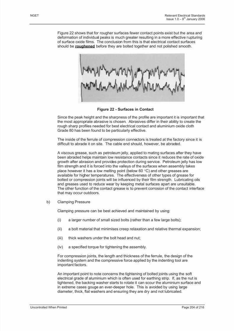
8/3/2019 1 Relevant Standards for Substation Plants
http://slidepdf.com/reader/full/1-relevant-standards-for-substation-plants 211/223
NGET Relevant Electrical StandardsIssue 1.0 – 9
thJanuary 2006
Uncontrolled When Printed Page 204 of 216
Figure 22 shows that for rougher surfaces fewer contact points exist but the area anddeformation of individual peaks is much greater resulting in a more effective rupturingof surface oxide films. The conclusion from this is that electrical contact surfacesshould be roughened before they are bolted together and not polished smooth.
Figure 22 - Surfaces in Contact
Since the peak height and the sharpness of the profile are important it is important thatthe most appropriate abrasive is chosen. Abrasives differ in their ability to create therough sharp profiles needed for best electrical contact and aluminium oxide clothGrade 80 has been found to be particularly effective.
The inside of the ferrule of compression connectors is treated at the factory since it isdifficult to abrade it on site. The cable end should, however, be abraded.
A viscous grease, such as petroleum jelly, applied to mating surfaces after they havebeen abraded helps maintain low resistance contacts since it reduces the rate of oxidegrowth after abrasion and provides protection during service. Petroleum jelly has lowfilm strength and it is forced into the valleys of the surfaces when assembly takes
place however it has a low melting point (below 60 C) and other greases areavailable for higher temperatures. The effectiveness of other types of grease for bolted or compression joints will be influenced by their film strength. Lubricating oilsand greases used to reduce wear by keeping metal surfaces apart are unsuitable.The other function of the contact grease is to prevent corrosion of the contact interfacethat may occur outdoors.
b) Clamping Pressure
Clamping pressure can be best achieved and maintained by using:
(i) a larger number of small sized bolts (rather than a few large bolts);
(ii) a bolt material that minimises creep relaxation and relative thermal expansion;
(iii) thick washers under the bolt head and nut;
(iv) a specified torque for tightening the assembly.
For compression joints, the length and thickness of the ferrule, the design of theindenting system and the compressive force applied by the indenting tool areimportant factors.
An important point to note concerns the tightening of bolted joints using the softelectrical grade of aluminium which is often used for earthing strip. If, as the nut istightened, the backing washer starts to rotate it can scour the aluminium surface andin extreme cases gouge an ever-deeper hole. This is avoided by using largediameter, thick, flat washers and ensuring they are dry and not lubricated.
8/3/2019 1 Relevant Standards for Substation Plants
http://slidepdf.com/reader/full/1-relevant-standards-for-substation-plants 212/223
NGET Relevant Electrical StandardsIssue 1.0 – 9
thJanuary 2006
Uncontrolled When Printed Page 205 of 216
23.5.4 Dissimilar Metals in Contact
This is an important topic and one that has created more interface or contact problems withbolted joints than almost anything else. One of the most common scenarios is aluminiumearthing tape used above ground but connected to an underground earth mat made of copper. The aluminium and copper must be bonded above ground using an appropriate
technique such as brazing or bolting. Since aluminium and copper are distant within theelectrochemical scale aluminium is strongly anodic and copper is strongly cathodic. Thisleads to copper/aluminium joints being very susceptible to progressive erosion of thealuminium and to jacking due to the production of corrosion products. This is particularly thecase in the presence of moisture and overwrapping the completed joint with a proprietarytape or using a pre-impregnated heat shrink tube over the joint are good preventivemeasures. Consideration should also be given to the location of the bolted joint particularlywhen maintenance procedures may require future examinations.
It is important to note that some metal combinations are inherently unstable.
Experience has shown that copper - copper connections are very secure and they are onlylikely to degrade at high temperatures. Nevertheless, it is common practice to tin or silver
plate the mating surfaces since the contact is superior over a wide temperature range andabrasion of the surfaces prior to assembly is unnecessary. This is because the nature andamount of oxide formation on tin and silver is such that it is broken under modest pressureswithout the need for high sharp peaks. Excessive tarnishing should still be removed by verylight abrasion.
Aluminium - aluminium connections are less secure and much care is needed over surfacepreparation, greasing and clamping to ensure stable joints. Plating of aluminium with tin,silver or even nickel is possible but difficult and this is normally reserved for specialapplications.
Copper-aluminium connections used for carrying load current have often suffered fromoverheating. This is not associated with bimetallic corrosion but is thought to be due partiallyto differential expansion forces and partially to lack of intermolecular adhesion of the metal-metal contact points.
In summary, the most stable joints are those between like interfaces and the most unstableare those between dissimilar interfaces where the factors mentioned above can bedominant. Aluminium-aluminium and tin-plated aluminium- tin-plated copper would beregarded as stable joints but aluminium - copper and aluminium-tin-plated copper wouldhave a tendency to be unstable particularly at continuous high operating temperatures.
Fitting of a metallic insert is a technique designed to fulfil two roles. First, it overcomes anyfundamental incompatibility that may exist between two metals that need to be boltedtogether. For example, both copper and aluminium form a stable interface with brass and
the insertion of a brass disc between copper and aluminium overcomes the inherentincompatibility of these two materials. Second the insert can be profiled to ensurepenetration of tenacious oxide films and provide good contact without the need for surfaceabrasion. The brass metallic insert developed by CEGB engineers and made and marketedby Sicame is an example of such a product.
There are other proprietary ways of combating incompatibility of mating surfaces andproviding satisfactory test data is available these may be used. An example is the use of copper clad aluminium (cupal) which combines the lightness and economy of aluminium withthe good contact properties of copper. The copper is factory extruded over an aluminiumsection under a very high pressure. Cut edges and bolt holes made in this clad material area potential source of corrosion and grease protection of these exposed surfaces is desirable.

8/3/2019 1 Relevant Standards for Substation Plants
http://slidepdf.com/reader/full/1-relevant-standards-for-substation-plants 213/223
NGET Relevant Electrical StandardsIssue 1.0 – 9
thJanuary 2006
Uncontrolled When Printed Page 206 of 216
23.6 RESISTANCE MEASUREMENT
Resistance measurements are important at the commissioning stage to ensure the jointingprocedures have been correctly implemented. Routine measurements of the resistances of critical items of plant throughout their service life are also needed to check there has been
no significant deterioration.
The joints covered in this document are all large and their electrical resistance is low.Values can range from as little as 2 µ for large busbar connections to a few hundredmicrohms for small cable connections. Even poorly made joints will still have a relatively lowresistance and so it is important to be able to make accurate measurements of resistance todetect joints that are not satisfactory for service.
Accurate field measurements of such low values of resistance can only be achieved byspecialist equipment which is widely available. Perhaps the best known in the UK is theChance Digital Micro Ohmmeter (DMO) which was developed by CEGB engineers in theearly 1970's and has been progressively refined since then. The term Ducter was coined for this instrument at the time although this was actually the trade name of an earlier instrument
used for low resistance measurements.
The DMO, which can measure resistance from 0.1µ to 10, operates using a four-wiremeasurement technique to obtain the necessary accuracy. Figure 23 shows how the four connections are made between the resistance under test and the DMO.
The connection of the test instrument is either by way of individual voltage and currentconnection leads using mole clamps or by combined voltage/current hand held probes.Convention is for combined voltage/current probes to be used when resistancemeasurements are required across short spans on rigid conductors, such as acrossconnectors to equipment palms. Individual current/voltage leads are used for longer spanssuch as the measurement of complete multiple circuit breaker interrupter heads or whereflexible conductors are at the connection points.
A precise current is passed through the joint from a position sufficiently remote to ensureuniformly distribution in the cross-section of the joint. For stranded conductors where theremay be significant inter-strand contact resistance this distance should be at least tendiameters. The distance can be shorter for solid conductors. If the current leads are movedfurther in or out and the reading displayed on the instrument changes, this is evidence thatthe current leads are too close to the joint being measured.
The voltage measurement leads are positioned such that only the voltage developed acrossthe joint is measured. The instrument passes current through the joint in both directions andthe resistance is calculated within the instrument (V/I) using the average of the twomeasured voltages. This averaging is intended to combat the effect of thermal emfs whichcan be of a similar magnitude to the voltage developed across the joint due to current flow.

8/3/2019 1 Relevant Standards for Substation Plants
http://slidepdf.com/reader/full/1-relevant-standards-for-substation-plants 214/223
NGET Relevant Electrical StandardsIssue 1.0 – 9
thJanuary 2006
Uncontrolled When Printed Page 207 of 216
Figure 23 - A typical Digital Micro Ohmmeter (DMO)
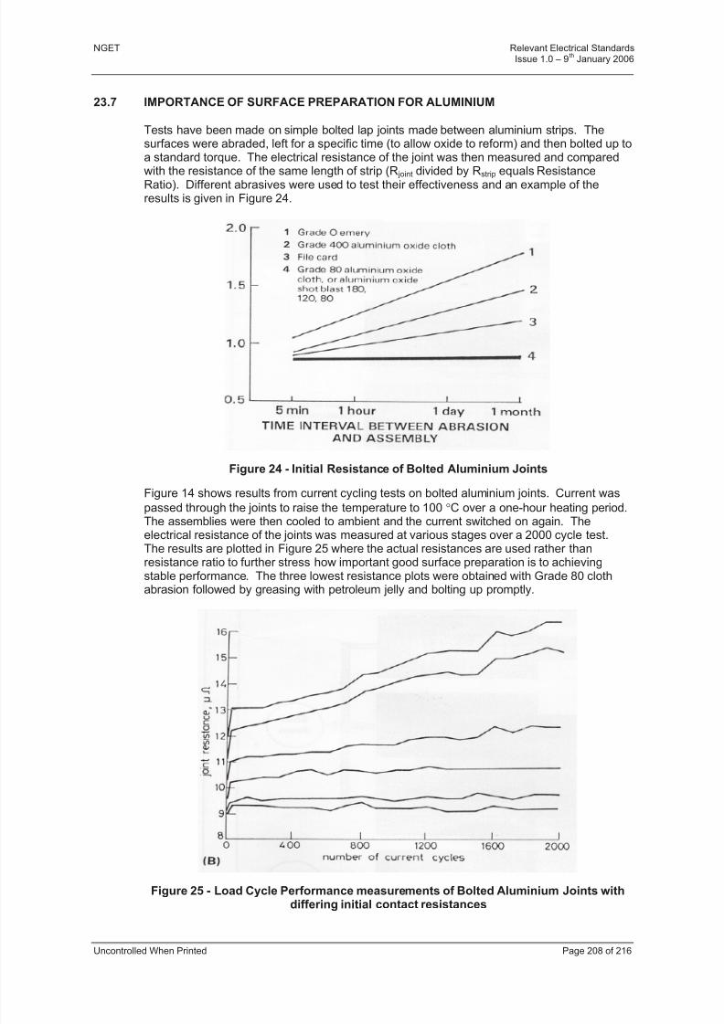
8/3/2019 1 Relevant Standards for Substation Plants
http://slidepdf.com/reader/full/1-relevant-standards-for-substation-plants 215/223
NGET Relevant Electrical StandardsIssue 1.0 – 9
thJanuary 2006
Uncontrolled When Printed Page 208 of 216
23.7 IMPORTANCE OF SURFACE PREPARATION FOR ALUMINIUM
Tests have been made on simple bolted lap joints made between aluminium strips. Thesurfaces were abraded, left for a specific time (to allow oxide to reform) and then bolted up toa standard torque. The electrical resistance of the joint was then measured and compared
with the resistance of the same length of strip (R joint divided by Rstrip equals ResistanceRatio). Different abrasives were used to test their effectiveness and an example of theresults is given in Figure 24.
Figure 24 - Initial Resistance of Bolted Aluminium Joints
Figure 14 shows results from current cycling tests on bolted aluminium joints. Current was
passed through the joints to raise the temperature to 100 C over a one-hour heating period.The assemblies were then cooled to ambient and the current switched on again. Theelectrical resistance of the joints was measured at various stages over a 2000 cycle test.The results are plotted in Figure 25 where the actual resistances are used rather thanresistance ratio to further stress how important good surface preparation is to achievingstable performance. The three lowest resistance plots were obtained with Grade 80 clothabrasion followed by greasing with petroleum jelly and bolting up promptly.
Figure 25 - Load Cycle Performance measurements of Bolted Aluminium Joints withdiffering initial contact resistances

8/3/2019 1 Relevant Standards for Substation Plants
http://slidepdf.com/reader/full/1-relevant-standards-for-substation-plants 216/223
NGET Relevant Electrical StandardsIssue 1.0 – 9
thJanuary 2006
Uncontrolled When Printed Page 209 of 216
23.8 FURTHER INFORMATION ON BOLTING
Bolted aluminium joints are more sensitive to variations in clamping load and pressure thancopper joints and the guidance given below will be more than adequate for other arrangements. This information is to help in those situations where no other information or instructions are provided. Many items of plant are assembled according to specific
information provided by manufacturer or supplier and the instructions should always befollowed.
It is preferable to use a larger number of small bolts rather than a few large bolts, (themaximum bolt size should typically be no bigger than M12). The reasons are:
e) The clamping load is more uniformly distributed over the overlap area.
f) There is more strain energy in the clamping assembly which minimises loss inclamping load due to creep in service.
g) Large bolts need a proportionally greater torque for the same bolt load which can bedifficult to achieve in practice.
The number and size of bolts for various aluminium busbar arrangements has beendetermined from tests. Empirical rules have been used to aid design as follows:
h) Total clamping load N (Newton per bolt x number of bolts) divided by current rating
(kA) should be not less than 50 i.e. N/A 50.
i) The washer clamping pressure (load on bolt divided by washer area) should bearound 40 i.e. N/mm
2= 40.
These clamping loads and pressures apply to grade 8.8 steel bolts. From this, the torquevalues may be calculated for the bolt sizes used. Reference 1 contains useful information on
typical bolting arrangements. Alternatives to steel bolts (such as aluminium or brass) can beused but this is outside the scope of this guidance. Some designers offset the loss of clamping load in service with Belleville washers. These should not be necessary if theabove empirical rules are followed.
Aluminium used for earthing strip and other applications where flexibility is important (grade1350) is very soft. If washers under the nut and bolt head are too thin they will dish as thenut is tightened and can be driven into the aluminium making it impossible to achieve thenecessary torque on the bolt. The backing washers supplied should always be used and, if none are available, washers that are at least 2 mm thick should be obtained. Table 36 is aguide to bolting torque and washer sizes.
Washer Dimensions – mm Bolt SizeGrade 8.8
steel
Bolt Torque(Nm)
Inside diameter Outside diameter Thickness
M6 7 6.4 14 2.0
M8 20 8.4 21 2.2
M10 35 10.5 24 2.4
M12 50 12.8 28 3.0
M16 90 16.8 34 3.4
Table 36 - Bolting Guide for Aluminium Joints

8/3/2019 1 Relevant Standards for Substation Plants
http://slidepdf.com/reader/full/1-relevant-standards-for-substation-plants 217/223
NGET Relevant Electrical StandardsIssue 1.0 – 9
thJanuary 2006
Uncontrolled When Printed Page 210 of 216
23.9 INFRARED TEMPERATURE MEASUREMENTS
This non-contact method is particularly suited to high voltage connections sincemeasurements can be made safely and speedily by scanning the joints in turn and noting thereadings obtained. The reading from the instrument, in degrees centigrade, is only anaccurate measure of joint temperature if the emissivity of the joint surface is also known
precisely. Since the temperature of a joint at any point in time is dependant on the level of current flowing and the degree of cooling (wind speed, air temperature, presence or lack of sun), the actual temperature is less important than the relative temperature of the jointcompared to the conductor alongside. Since a joint is larger in surface area than theconductor and thus better cooled, and with a lower initial electrical resistance, it should runcooler than the conductor. Thus, if when making a routine infrared scan, a joint appears tobe running hotter than the adjacent conductor, it is suspect. The degree of urgency for investigating the matter further is dependent on how much hotter the joint is running and thisitself is a function of load current and weather conditions at the time. Good practicetherefore dictates that infrared measurements be undertaken when sizeable load current isflowing and weather conditions are calm. Under these conditions, temperature differences
between joint and conductor exceeding 5C are an indication that the joint is suspect and itshould be taken out of service and re-made at the next available outage. Temperature
differences in excess of 10C dictate that more rapid action be taken i.e. urgent joint repair or that frequent surveillance be carried out using a hand held infrared camera to monitor thedeterioration rate, so that the potential failure risks can be managed until the repair is done.
23.10 REFERENCES
1 THOMAS, A.G. and RATA, P.J.H.: “Aluminium Busbar” (Hutchinson, 1960)
2 Aluminium electrical conductor handbook (The Aluminium Association, New York1971)
3 JACKSON, R.L.: “Significance of surface preparation for bolted aluminium joints”, IEE
Proc. C, Gen., Trans. & Distrib., 1981, 128,(2), pp. 45-54
4 “Aluminium in contact with other materials”, Information bulletin 21, The AluminiumDevelopment Association, 1955
5 JACKSON, R.L.: “Electrical performance of aluminium/copper bolted joints”, IEE Proc.C,
6 Gen., Trans. & Distrib., 1982, 129,(4), pp. 177-184
23.10.1 Subsidiary References
7 COPPER DEVELOPMENT ASSOCIATION, 1988, “Copper for Busbars”, C.D.A.
Publication No.22
8 JACKSON, R.L.: “Proposals for the elimination of hot joints on generator flexibleconnections”, CERL Note No. TPRD/L/2270/N82
9 JACKSON, R.L.: “The CERL Transition washer”, CERL Report No. TPRD/L/2440/R83
10 JACKSON, R.L.: “The preparation and performance of bolted joints using grade 1350aluminium busbar”, CERL Report No. RD/L/R2010
11 JACKSON, R.L. AND PRICE, C.F.: “A test set for low resistance measurements”,CERL Note No RD/L/lN252/73
12 JACKSON, R.L.: “Jointing by cold pressure welding”, Distribution Developments,September 1987
8/3/2019 1 Relevant Standards for Substation Plants
http://slidepdf.com/reader/full/1-relevant-standards-for-substation-plants 218/223
NGET Relevant Electrical StandardsIssue 1.0 – 9
thJanuary 2006
Uncontrolled When Printed Page 211 of 216
13 JACKSON, R.L.: “Cold pressure lap welding of copper earthing strip”, CERL Note NoTPRD/L/2896/N85
14 PARR, D.J.: “Cold pressure lap welding of thick aluminium and copper earth strip”,CERL Note No. RD/L/N185/79
15 PARR,D.J: “Development and service application of cold pressure welding for jointingthick aluminium and copper earth strip”, CERL Note No. TPRD/L/2395/N82
16 PARR,D.J: “Weathering trials on earth strip joints”, CERL Note No. TPRD/L/2825/N85
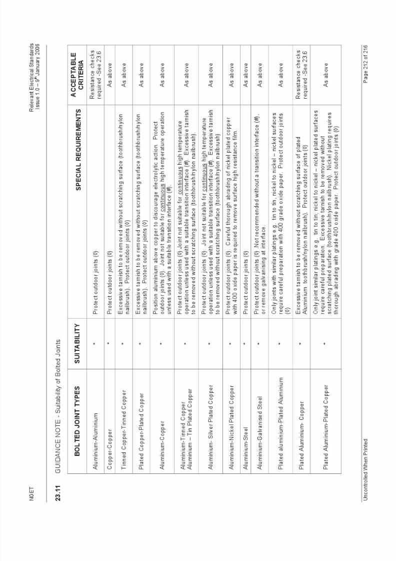
8/3/2019 1 Relevant Standards for Substation Plants
http://slidepdf.com/reader/full/1-relevant-standards-for-substation-plants 219/223
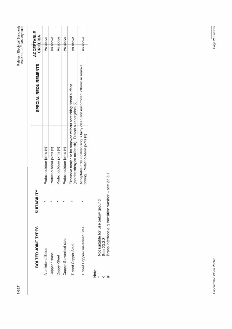
8/3/2019 1 Relevant Standards for Substation Plants
http://slidepdf.com/reader/full/1-relevant-standards-for-substation-plants 220/223
N G E T
R e l e v a n t E l e c t r i c a l S t a n d a r d s
I s s u e 1 . 0 – 9 t h J a n u a r y 2 0 0 6
U n c o n t r o
l l e d W h e n P r i n t e d
P a g e 2 1 3 o f 2 1 6
B O L T E D J O I N T T Y P E S
S U I T A B I L I T Y
S P E C I A L R E Q U I R E M E N T S
A
C C E P T A B L E
C R I T E R I A
A l u m i n i u m / B r a s s
*
P r o t e c t o u
t d o o r j o i n t s ( )
A s a b o v e
C o p p e r / B r a s s
*
P r o t e c t o u
t d o o r j o i n t s ( )
A s a b o v e
C o p p e r - S t e e l
*
P r o t e c t o u
t d o o r j o i n t s ( )
A s a b o v e
C o p p e r - G a l v a n i s e d s t e e l
*
P r o t e c t o u
t d o o r j o i n t s ( )
A s a b o v e
T i n n e d C o p p e r - S t e e l
*
E x c e s s i v e
t a r n i s h t o b e r e m o v e d w i t h o u t s c r a t c h i n g t i n n e d s u r f a c e
( t o o t h b r u s h / n y l o n n a i l b r u s h ) . P r o t e c t o u t d o o r j o
i n t s ( )
A s a b o v e
T i n n e d C o p p e r - G a l v a n i s e d S t e e l
*
A c c e p t a b l e o n l y i f g a l v a n i s i n g i s f a i r l y c l e a n a n d
u n c o r r o d e d , o t h e r w i s e r e m o v e
t i n n i n g . P r o t e c t o u t d o o r j o i n t s ( )
A s a b o v e
N o t e :
*
N o t s u i t a b l e f o r u s
e b e l o w g r o u n d
S e e 2 3 . 3 . 3
#
B r a s s i n t e r f a c e e . g
t r a n s i t i o n w a s h e r – s e e 2 3 . 3 . 1
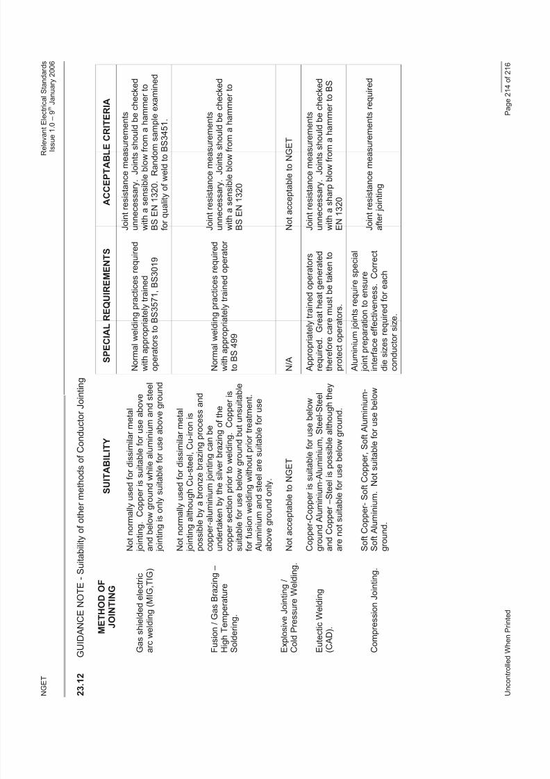
8/3/2019 1 Relevant Standards for Substation Plants
http://slidepdf.com/reader/full/1-relevant-standards-for-substation-plants 221/223
N G E T
R e l e v a n t E l e c t r i c a l S t a n d a r d s
I s s u e 1 . 0 – 9 t h J a n u a r y 2 0 0 6
U n c o n t r o
l l e d W h e n P r i n t e d
P a g e 2 1 4 o f 2 1 6
2 3 . 1 2
G U I D A N C E N O T E - S u i t a b i l i t y
o f o t h e r m e t h o d s o f C o n d u c t o r J o
i n t i n g
M E T H O D O F
J O I N T I N G
S U I T A B I L I T Y
S P E C I A L R E Q U I R E M E N T S
A C C E P T A B L E C R
I T E R I A
G a s s h i e l d e d e l e c t r i c
a r c w e l d i n g ( M I G , T I G )
N o t n o r m a l l y u s e d f o r d i s s i m i l a r m e t a l
j o i n t i n g . C o p p e r i s s u i t a b l e f o r u s e a b o v
e
a n d b e l o w g r o u n d w h i l e a l u m i n i u m a n d s t e e l
j o i n t i n g i s o n l y s u i t a b l e f o r u s e a b o v e g r o u n d
N o r m a l w e l d i n g p r a c t i c e s r e
q u i r e d
w i t h a p p r o p r i a t e l y t r a i n e d
o p e r a t o r s t o B S 3 5 7 1 , B S 3 0 1 9
J o i n t r e s i s t a n c e m e a s u r e m
e n t s
u n n e c e s s a r y . J o i n t s s h o u
l d b e c h e c k e d
w i t h a s e n s i b l e b l o w f r o m a h a m m e r t o
B S E N 1 3 2 0 . R a n d o m s a m p l e e x a m i n e d
f o r q u a l i t y o f w e l d t o B S 3 4
5 1 .
F u s i o n / G a s B r a z i n g –
H i g h T e m p e r a t u r e
S o l d e r i n g .
N o t n o r m a l l y u s e d f o r d i s s i m i l a r m e t a l
j o i n t i n g a l t h o u g h C u - s t e e l , C u - i r o n i s
p o s s
i b l e b y a b r o n z e b r a z i n g p r o c e s s a n
d
c o p p
e r - a l u m i n i u m j o i n t i n g c a n b e
u n d e
r t a k e n b y t h e s i l v e r b r a z i n g o f t h e
c o p p
e r s e c t i o n p r i o r t o w e l d i n g . C o p p e r
i s
s u i t a
b l e f o r u s e b e l o w g r o u n d b u t u n s u i t
a b l e
f o r f u
s i o n w e l d i n g w i t h o u t p r i o r t r e a t m e n
t .
A l u m
i n i u m a n d s t e e l a r e s u i t a b l e f o r u s e
a b o v
e g r o u n d o n l y .
N o r m a l w e l d i n g p r a c t i c e s r e
q u i r e d
w i t h a p p r o p r i a t e l y t r a i n e d o p
e r a t o r
t o B S 4 9 9
J o i n t r e s i s t a n c e m e a s u r e m
e n t s
u n n e c e s s a r y . J o i n t s s h o u
l d b e c h e c k e d
w i t h a s e n s i b l e b l o w f r o m a h a m m e r t o
B S E N 1 3 2 0
E x p l o s i v e J o i n t i n g /
C o l d P r e s s u r e W e l d i n g .
N o t a c c e p t a b l e t o N G E T
N / A
N o t a c c e p t a b l e t o N G E T
E u t e c t i c W e l d i n g
( C A D ) .
C o p p e r - C o p p e r i s s u i t a b l e f o r u s e b e l o w
g r o u n d A l u m i n i u m - A l u m i n i u m , S t e e l - S t e
e l
a n d C o p p e r – S t e e l i s p o s s i b l e a l t h o u g h
t h e y
a r e n
o t s u i t a b l e f o r u s e b e l o w g r o u n d .
A p p r o p r i a t e l y t r a i n e d o p e r a t o r s
r e q u i r e d . G r e a t h e a t g e n e r a t e d
t h e r e f o r e c a r e m u s t b e t a k e n t o
p r o t e c t o p e r a t o r s .
J o i n t r e s i s t a n c e m e a s u r e m
e n t s
u n n e c e s s a r y . J o i n t s s h o u
l d b e c h e c k e d
w i t h a s h a r p b l o w f r o m a h
a m m e r t o B S
E N 1 3 2 0
C o m p r e s s i o n J o i n t i n g .
S o f t
C o p p e r - S o f t C o p p e r , S o f t A l u m i n i u
m -
S o f t
A l u m i n i u m . N o t s u i t a b l e f o r u s e b e l o w
g r o u n d .
A l u m i n i u m j o i n t s r e q u i r e s p e
c i a l
j o i n t p r e p a r a t i o n t o e n s u r e
i n t e r f a c e e f f e c t i v e n e s s . C o r
r e c t
d i e s i z e s r e q u i r e d f o r e a c h
c o n d u c t o r s i z e .
J o i n t r e s i s t a n c e m e a s u r e m
e n t s r e q u i r e d
a f t e r j o i n t i n g
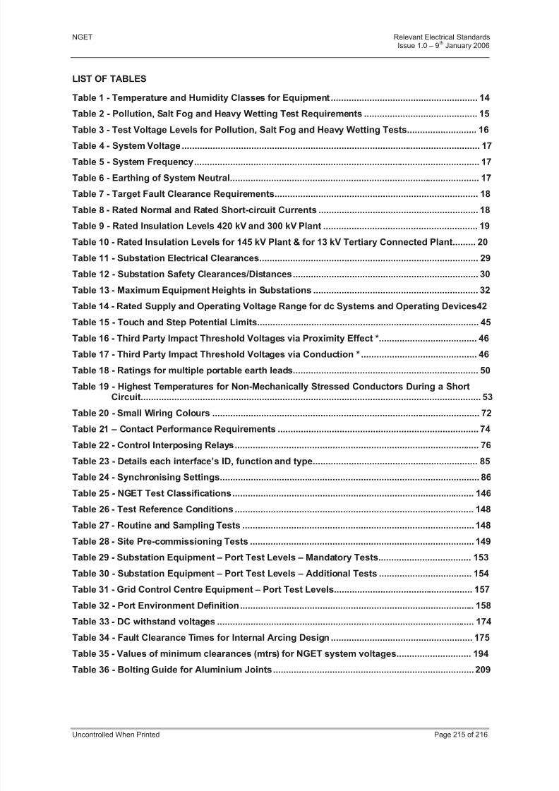
8/3/2019 1 Relevant Standards for Substation Plants
http://slidepdf.com/reader/full/1-relevant-standards-for-substation-plants 222/223
NGET Relevant Electrical StandardsIssue 1.0 – 9
thJanuary 2006
Uncontrolled When Printed Page 215 of 216
LIST OF TABLES
Table 1 - Temperature and Humidity Classes for Equipment......................................................... 14
Table 2 - Pollution, Salt Fog and Heavy Wetting Test Requirements ............................................ 15
Table 3 - Test Voltage Levels for Pollution, Salt Fog and Heavy Wetting Tests........................... 16
Table 4 - System Voltage.................................................................................................................... 17
Table 5 - System Frequency............................................................................................................... 17
Table 6 - Earthing of System Neutral................................................................................................. 17
Table 7 - Target Fault Clearance Requirements............................................................................... 18
Table 8 - Rated Normal and Rated Short-circuit Currents .............................................................. 18
Table 9 - Rated Insulation Levels 420 kV and 300 kV Plant ............................................................ 19
Table 10 - Rated Insulation Levels for 145 kV Plant & for 13 kV Tertiary Connected Plant......... 20
Table 11 - Substation Electrical Clearances..................................................................................... 29
Table 12 - Substation Safety Clearances/Distances........................................................................ 30
Table 13 - Maximum Equipment Heights in Substations ................................................................ 32
Table 14 - Rated Supply and Operating Voltage Range for dc Systems and Operating Devices42
Table 15 - Touch and Step Potential Limits...................................................................................... 45
Table 16 - Third Party Impact Threshold Voltages via Proximity Effect *...................................... 46
Table 17 - Third Party Impact Threshold Voltages via Conduction * ............................................. 46
Table 18 - Ratings for multiple portable earth leads........................................................................ 50
Table 19 - Highest Temperatures for Non-Mechanically Stressed Conductors During a ShortCircuit.................................................................................................................................... 53
Table 20 - Small Wiring Colours ........................................................................................................ 72
Table 21 – Contact Performance Requirements .............................................................................. 74
Table 22 - Control Interposing Relays............................................................................................... 76
Table 23 - Details each interface’s ID, function and type................................................................ 85
Table 24 - Synchronising Settings..................................................................................................... 86
Table 25 - NGET Test Classifications.............................................................................................. 146
Table 26 - Test Reference Conditions ............................................................................................. 148
Table 27 - Routine and Sampling Tests .......................................................................................... 148
Table 28 - Site Pre-commissioning Tests ....................................................................................... 149Table 29 - Substation Equipment – Port Test Levels – Mandatory Tests.................................... 153
Table 30 - Substation Equipment – Port Test Levels – Additional Tests .................................... 154
Table 31 - Grid Control Centre Equipment – Port Test Levels...................................................... 157
Table 32 - Port Environment Definition........................................................................................... 158
Table 33 - DC withstand voltages .................................................................................................... 174
Table 34 - Fault Clearance Times for Internal Arcing Design ....................................................... 175
Table 35 - Values of minimum clearances (mtrs) for NGET system voltages............................. 194
Table 36 - Bolting Guide for Aluminium Joints.............................................................................. 209

8/3/2019 1 Relevant Standards for Substation Plants
http://slidepdf.com/reader/full/1-relevant-standards-for-substation-plants 223/223
NGET Relevant Electrical StandardsIssue 1.0 – 9
thJanuary 2006
LIST OF FIGURES
Figure 1 - Governance of Electrical Standards- Amendment Process............................................ 4
Figure 2 - Reduced Clearance to Substation Perimeter Fence (400kV Clearances Shown) ....... 31
Figure 3 - Example High Frequency Earth Installation for Surge Arrester.................................... 58
Figure 4 - Incoming supply transformer sited within NGET substation........................................ 59
Figure 5 - Incoming supply transformer sited outside NGET substation...................................... 60
Figure 6 - Outgoing supply transformer sited within NGET substation........................................ 60
Figure 7 - Example installation of insulating bushes on palisade fence....................................... 61
Figure 8 – Example of earthing connection box with test facility*................................................. 62
Figure 9 - Synchronising Functional Interfaces............................................................................... 84