1 rechner bausteinverzeichnis - ibhsoftec · table of contents page 1 tti trans tech...
TRANSCRIPT

TTI Trans Tech International© 2009 S5 for Windows® Training
Getting Started with
S5 for Windows® Version 6.x
I N G E N I E U R B Ü R O F Ü R TECHNOLOGIE TRANSFERDIPL.-ING. B. P. SCHULZ-HEISE

S5 for Windows® Training TTI Trans Tech International© 2009
Content The author has created this document to assist users of S5 for Windows® Version 6.X. In no way is the author responsible for the completeness or quality of the information provided. Liability claims regarding damage caused by the use of any information provided, will not be accepted. Part or all of the pages in the publication can be edited, altered, in part, or completely deleted by the author without separate announcement.
Copyright The author has not knowingly used any copyrighted material for this publication. The copyright for any material created by the author is reserved. Any duplication or use of objects such as diagrams or texts in other printed publications is not permitted without the author's agreement.
Legal validity of this disclaimer. This disclaimer is to be regarded as part of the publication which you were supplied as a customer of S5 for Windows® Version 6.X. If sections or individual terms of this statement are not legal or correct, the content or validity of the other parts remain in force.
Complete training classes available for S5 for Windows®; S7 for Windows®; and also for the Siemens PLC Programming Software Step® 7.
Author: TTI Ingenieurbüro für Technologie Transfer Dipl. Ing. B. Peter Schulz-Heise Stadtring 207 64720 Michelstadt Germany
Editor: Trans Tech International John Teachout 36 Belmont Road Suite W22 West Harwich, MA 02671 USA
Tel.: + 1 781 455 6827 Home page: TTIntl.com
Fax: 866 254 5215 E-Mail: [email protected]
Simatic S5, Step 5, Simatic S7, MicroWin, Step 7, Graph5, S7-200, S7-300, S7-400, MPI, DP, PPI and CP are registered trademarks of Siemens Aktiengesellschaft, Berlin und München. . Picture Source: "© Siemens AG 2002, All rights reserved" Windows is a registered trademark of Microsoft Corporation. Excel is a registered trademark of Microsoft Corporation in the United States and other countries. InTouch® and Wonderware® are registered trademarks of the Wonderware Corporation. Product names are trademarks of their owners.

Table of Contents Page 1
TTI Trans Tech International© 2009 S5 for Windows® Training
Table of Contents
Table of Contents ............................................................................. 1
1 S5 for Windows® Basics ....................................................... 1-1
1.1 Opening the S5 for Windows® Software .................................... 1-1
1.2 S5 for Windows® Basic Window (Classic Operator interface) . 1-4
Title Bar ..................................................................................................... 1-5
1.3 Generating a S5 Project ............................................................. 1-10
1.4 Selecting the English Mnemonics ............................................. 1-13
1.5 S5 for Windows® Basic Window (Standard interface) ............ 1-14
Opening the S5 for Windows® Software .................................................1-14 S5 for Windows Basic® Window .............................................................1-14 Title Bar ...................................................................................................1-15 Tool Bar – Standard Operator Interface ..................................................1-16
1.6 File (File Menu - PC Block List) ................................................. 1-18
New (New Project) ...................................................................................1-18 Save Online Blocks..................................................................................1-19 Restore Online Blocks .............................................................................1-19 Transfer Project to the PLC .....................................................................1-20 Search For ...............................................................................................1-21 Replace ....................................................................................................1-22 Compress PLC Memory ..........................................................................1-22 Clear / Reset PLC ....................................................................................1-23 Copy from RAM to ROM ..........................................................................1-24 PLC State ................................................................................................1-24 Interrupt Stack (I-Stack) ...........................................................................1-24 Block Stack (B-Stack) ..............................................................................1-26 S5 System Data .......................................................................................1-27 S5 Memory usage ....................................................................................1-27 PLC Access Permission ..........................................................................1-29 PLC Access Permission ..........................................................................1-29 Preferences .............................................................................................1-30 Block View Tab ........................................................................................1-30 Fonts Tab .................................................................................................1-34 Write Protect Tab .....................................................................................1-35 Print..........................................................................................................1-35

Page 2 Table of Contents
S5 for Windows® Training TTI Trans Tech International© 2009
Print Settings ........................................................................................... 1-36 Font ......................................................................................................... 1-38 Header .................................................................................................... 1-38 Footer ...................................................................................................... 1-38 Footer Field abbreviations ...................................................................... 1-39 Connect to the last selected PLC ............................................................ 1-39 Connect to the last selected PLC ............................................................ 1-39
2 S5 for Windows® Online Functions ..................................... 2-1
2.1 Connecting the S5 PLC with a PC ............................................... 2-1
2.2 Transferring all PLC Blocks of a STEP® 5 / S5W Project to the PLC ................................................................ 2-6
Transferring a STEP® 5 Project to the PLC ............................................. 2-6 Transferring a S5W Project to the PLC..................................................... 2-7
2.3 Transferring a PLC Program or PLC Blocks to the PC .............. 2-8
3 S5 for Windows® Tools to Debug a S5 PLC Program ........ 3-1
3.1 Opening a S5 PLC Program saved in a “S5 Project” ................. 3-1
3.2 Comparing the existing Online and Offline PLC Program ......... 3-3
Compare Tool ........................................................................................... 3-3 Differences in Code................................................................................... 3-5
3.3 Arranging Window in the Workplace ........................................... 3-6
3.4 PLC Block Status display ............................................................. 3-7
Activating the Status ................................................................................. 3-7 Status Display, Statement List (STL) Presentation ................................... 3-8 Status Display, Ladder Logic (LAD) Presentation .................................... 3-8 Status Display, Control System Flowchart (CSF) Presentation ................ 3-9
Chapter 1 S5 for Windows® Basics Page 1-1
TTI Trans Tech International© 2009 S5 for Windows® Training
1 S5 for Windows® Basics
To work with S5 for Windows® basic skills are necessary.
1.1 Opening the S5 for Windows® Software
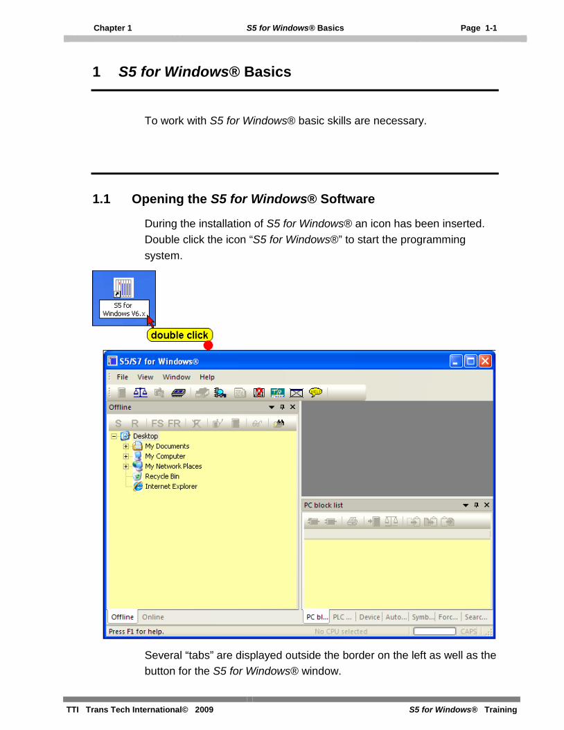
During the installation of S5 for Windows® an icon has been inserted. Double click the icon “S5 for Windows®” to start the programming system.
Several “tabs” are displayed outside the border on the left as well as the button for the S5 for Windows® window.

Page 1-2 S5 for Windows® Basics Chapter 1
S5 for Windows® Training TTI Trans Tech International© 2009
We recommend the following settings for easier use of S5 for Windows®.
1. Close all unnecessary windows.
Open the “View” menu and select the “Offline tree” and “Online tree”. Deselect all other views.
The “Offline tree” is used to select the “S5 Project” you want to work with. The S5 Project contains the files necessary for a S5 PLC program. Further on it will be explained how to generate a S5 Project. An S5 Project is always required to work with a S5 PLC program executed on a PLC.
The “Online tree” is used to select the PLC to be connected with.

Chapter 1 S5 for Windows® Basics Page 1-3
TTI Trans Tech International© 2009 S5 for Windows® Training
2. Using the “Auto Hide” functions.
It is recommended that you use the “Auto Hide” icon to lock the tab at the outside border of S5 for Windows®. By bringing the mouse pointer to the tab, the window will open automatically.
Use the “Auto Hide” icon to close the “Offline tree” and the “Online tree”.
3. Operator Interface mode.
Version 6.x of S5 for Windows® has a new concept for opening and closing windows in the workplace.
You can use the “Auto Hide” icon to lock the tab at the outside border of the workplace. By moving the mouse pointer to the tab, the window will open automatically. As soon as the mouse pointer leaves the automatically opened window, the window is closed.
If you click at tab the opened window will stay open until it is closed.

Page 1-4 S5 for Windows® Basics Chapter 1
S5 for Windows® Training TTI Trans Tech International© 2009
Classic Operator Interface
If the “Classic operator interface” mode is selected, the “Tool Bar” is extended and the open windows will stay open until they are closed.
To select the previously described mode, click “Classic operator interface” in the “Window” menu.
1.2 S5 for Windows® Basic Window (Classic Operator interface)
In “Classic operator interface” mode the “PC Block List” window is open and fills the whole workplace.

Chapter 1 S5 for Windows® Basics Page 1-5
TTI Trans Tech International© 2009 S5 for Windows® Training
Title Bar
The title bar displays S5 for Windows®, and, if an additional Window is open in the workplace, the name of the open window is also displayed. The Icons are “Windows” specific.
Open Control menu
This icon opens the Control menu that contains the commands to Restore, Move, Size, Minimize, Maximize, or Close the open Window. The Keyboard shortcut is Alt + Spacebar.
Minimizing the open window to an icon
Clicking the button at the right side of the S5 for Windows title reduces the open window to the size of an icon (same function as the Minimize command from the Control menu).
Maximizing the open window
Clicking the Maximize button in the upper right corner of S5 for Windows will enlarge the window to its maximum size (same function as the Maximize command from the Control menu).
Restoring an enlarged window to its previous size
Clicking the Restore button in the upper right corner of S5 for Windows will restore an enlarged window to its previous size (same function as the Restore command from the Control menu).
Closing S5 for Windows
Clicking the Close button in the upper right corner of S5 for Windows will terminate S5 for Windows (same function as the Close command from the Control menu).
Menu Bar
The menu bar lists the available menus. The menus contain the available commands of S5 for Windows®. The menus in the menu bar change depending on the S5 for Windows® application windows opened. You can open a menu by clicking the name of the menu or by pressing the ALT key and then the first Letter of the menu name.

Page 1-6 S5 for Windows® Basics Chapter 1
S5 for Windows® Training TTI Trans Tech International© 2009
Open Control menu
This icon opens the Control menu that contains the commands to Restore, Move, Size, Minimize, Maximize, or Close the Window opened (active) in the workplace.
Tool Bar I – Classic Operator Interface
The tool bar provides instant access to frequently used S5 for Windows® commands. Click an icon with the mouse and the command is executed. You can reach these functions with the keyboard via the window menu and/or the function keys.
This tool bar is the same for all S5 for Windows® application windows (Classic operator interface mode).
Open next Window This icon allows you to switch rapidly between open windows with a mouse click. The keyboard shortcut Ctrl+F6 provides the same function.
PC (Personal Computer) Block List This index lists all the blocks with the date and time it was created or changed and a comment. One or more blocks may be selected for further manipulation.
PLC Block List This index lists all the blocks stored in the PLC. One or more blocks may be selected for further manipulation in the same way it is handled in the windows file manager.
EPROM / EEPROM / Flash EPROM Burner This icon opens a menu to control EPROM / EEPROM / Flash EPROM burning.
Cross Reference Display A click on this icon lists the appearance of operands, as a symbol or absolute, throughout the whole program. This function may be called from any window.

Chapter 1 S5 for Windows® Basics Page 1-7
TTI Trans Tech International© 2009 S5 for Windows® Training
Block Edit The block selected in the block listing will be displayed in the block editor and is ready for any changes. The keyboard shortcut F10 provides the same function.
Symbolic Table Editor With this easy to use integrated editor you can write, cut, copy and paste text to create and modify the symbol table. The symbol table may be tested for multiple uses of addresses or symbols. The symbol table can also be sorted by addresses or symbols.
PLC Error Display (I-Stack, B-Stack, Diagnostic Buffer) This icon enables you to view the program interrupt information stored in the PLC (I-Stack, B-Stack, Diagnostic Buffer). The information is displayed in real language with the faulty portion of the program.
On-line PLC Status The status of flags, inputs, outputs, timers, counters, comparators, data words, and peripheral words are displayed and can be modified.
Preferences This icon opens dialog boxes to customize the appearance of S5 for Windows®. The settings for the serial port, the editors, the indexes, the display font and other (miscellaneous) settings are saved and are reloaded whenever a new PLC project is opened.
PLC Block (Program) Compare S5 for Windows® offers a powerful PLC Program (Block Compare). The command Compare opens dialog boxes to select PLC Program files to compare (online and offline).
S7 Hardware configuration Only available with S7 for Windows®. Not used with STEP 5 PLC programs.
Dynamic PLC Block Display Enables fast switching between open PLC status windows.
Closing Open Windows The S5 for Windows® active window is closed by clicking this icon. The keyboard shortcut Ctrl+F4 provides the same function.

Page 1-8 S5 for Windows® Basics Chapter 1
S5 for Windows® Training TTI Trans Tech International© 2009
Help Function An integrated, subject related help file with an index and a list of keyboard shortcuts for easy operation is available. The keyboard shortcut F1 provides the same function.
Tool bar II (PLC Block List)
The tool bar II provides instant access to frequently used PC block list commands. Click an icon with the mouse and the command is executed. With the keyboard you can reach these functions via the file menu and the Block menu.
Create new PLC Block A dialog box to establish the name of the new block is opened. After entering the new Block, the Block Editor window is opened and ready for creating a new Block.
Edit Block The block selected in the block listing will be displayed in the block editor and is ready for any changes. The keyboard shortcut F10 provides the same function.
Print Block The marked block is printed. The keyboard shortcut Alt+B, R provides the same function.
Transfer Block to PLC The marked blocks are transferred to the PLC. The keyboard shortcut Alt+B, T provides the same function.
PLC Block Compare The marked Block is compared with the Block in the (online and offline compare).
Cut Block The marked blocks are transferred to a temporary buffer and are removed from the Block List. The keyboard shortcut Ctrl+X or Shift+Backspace provides the same function.

Chapter 1 S5 for Windows® Basics Page 1-9
TTI Trans Tech International© 2009 S5 for Windows® Training
Copy Block The marked blocks are transferred to a temporary buffer and remain in the Block List. The keyboard shortcut Ctrl+C or Ctrl+Insert provides the same function.
Paste Block The blocks currently in the temporary buffer are transferred to the PC block list. The blocks remain in the temporary buffer. The keyboard shortcut Ctrl+V or Shift+Insert provides the same function.
Workplace Column Title Bar
Clicking the title of a column will sort the PC Block List information in an ascending order. Clicking the title again will sort the information in a descending order.
The column width can be adjusted by dragging the column border with the mouse.
Workplace
All the blocks of an open PLC program file are listed in the PC block List. Additional application windows fill out the workplace.
Status Bar
The status bar may displays additional information on the open window and executed tasks.
Note:
The right mouse button may be used within the Workplace.
If the right mouse button is clicked, a menu with the most important commands is opened.

Page 1-10 S5 for Windows® Basics Chapter 1
S5 for Windows® Training TTI Trans Tech International© 2009
1.3 Generating a S5 Project
A new S5 Project can only be generated in an existing Folder.
It is not recommended that you generate a new project directly in the “My Documents” folder. You can name a new folder and put it in the “My Documents” folder, for instance “S5_Training”.
Generate a new “S5 Project” folder
Note: Windows with “Online – information” have a light green background.
Note: Windows with “Offline – information” have a light yellow background.
Note:
To “debug” a PLC program located in the PLC, you have to have the PLC program located in a S5 Project. This could be the original project with comments and symbols (preferable).
If the original project is not available you must download the PLC program into a newly generated S5 Project.

Chapter 1 S5 for Windows® Basics Page 1-11
TTI Trans Tech International© 2009 S5 for Windows® Training
Commands to open a new project
S5 for Windows® provides two possibilities to generate S5 projects:
• New STEP® 5 project.
• New S5W project.
It is recommended that you use “New S5W project”. More details about the PLC Programs and Blocks can be saved in a S5W project.
Use “New STEP® 5 project” only if you are frequently using the original Siemens STEP 5 programming software.
The following t explains the handling of a “New S5W project”.
• Click “New S5W project” in the File / New Menu.
• Select the “Path” in the “Save As” dialog box.
• Rename the S5 project in the “File name” field (Project1) if required and confirm with the “Save” button.

Page 1-12 S5 for Windows® Basics Chapter 1
S5 for Windows® Training TTI Trans Tech International© 2009
The S5W project with its name “PROJECT1” is listed in the “Offline – Tree”.
If the “Offline” tab is not shown, use the command “Offline tree” from the “File” menu.
It is recommended that you use the “Auto Hide” icon to lock the tab at the outside border of S5 for Windows®. By moving the mouse pointer to the tab the window will open automatically.
Note:
A “Project” is required to make a PLC user program. You also must have an open project to transfer and save an existing program from a PLC for backup purposes.

Chapter 1 S5 for Windows® Basics Page 1-13
TTI Trans Tech International© 2009 S5 for Windows® Training
1.4 Selecting the English Mnemonics
In the US, PLC programs are usually using English Mnemonics.
The selection changes the mnemonics of the instructions (key words) and the operands in the logic and the symbolic table. The selection will not change the language of the program (menu commands, symbols, comments, etc.).
The mnemonics to identify Bit-Memory, Timers, Counters, Inputs, Outputs, and the instruction set used for Statement List (STL) programming are identified with their English (International mnemonics) syntax.
Examples:
Input I Timer T OR O Output Q Counter C Count Down CD Flag F AND A Count Up CU

Page 1-14 S5 for Windows® Basics Chapter 1
S5 for Windows® Training TTI Trans Tech International© 2009
1.5 S5 for Windows® Basic Window (Standard interface)
Opening the S5 for Windows® Software
During the installation of S5 for Windows® an icon has been inserted. Double click the icon “S5 for Windows®” to start the programming system.
S5 for Windows Basic® Window
Note:
If you are not familiar with S5 for Windows® we recommend that you use the “Classic operator interface” (see chapter 1.2).

Chapter 1 S5 for Windows® Basics Page 1-15
TTI Trans Tech International© 2009 S5 for Windows® Training
Title Bar
The title bar displays S5 for Windows®, and, if an additional Window is open in the workplace, the name of the open window is also displayed. The Icons are “Windows” specific.
Open Control menu
This icon opens the Control menu that contains the commands to Restore, Move, Size, Minimize, Maximize, or Close the open Window. The Keyboard shortcut is Alt + Spacebar.
Minimizing the open window to an icon
Clicking the button at the right side of the S5 for Windows title reduces the open window to the size of an icon (same function as the Minimize command from the Control menu).
Maximizing the open window
Clicking the Maximize button in the upper right corner of S5 for Windows will enlarge the window to its maximum size (same function as the Maximize command from the Control menu).
Restoring an enlarged window to its previous size
Clicking the Restore button in the upper right corner of S5 for Windows will restore an enlarged window to its previous size (same function as the Restore command from the Control menu).
Closing S5 for Windows
Clicking the Close button in the upper right corner of S5 for Windows will terminate S5 for Windows (same function as the Close command from the Control menu).
Menu Bar
The menu bar contains a list of menus. You can open a menu by clicking the name of the menu or by pressing the ALT key and then the first Letter of the menu name.

Page 1-16 S5 for Windows® Basics Chapter 1
S5 for Windows® Training TTI Trans Tech International© 2009
Tool Bar – Standard Operator Interface
The tool bar provides instant access to frequently used S5 for Windows® commands. This tool bar is the same for all S5 for Windows® application windows. Click an icon with the mouse and the command is executed. You can reach these functions with the keyboard via the window menu and/or the function keys.
CPU Function (I-Stack, B-Stack, Diagnostic Buffer) This icon enables you to view the program interrupt information stored in the PLC (I-Stack, B-Stack, Diagnostic Buffer). The information is displayed in real language with the faulty portion of the program.
PLC Block (Program) Compare S5 for Windows® offers a powerful PLC Program (Block Compare). The command Compare opens dialog boxes to select PLC Program files to compare (online and offline).
S7 Hardware configuration Only available with S7 for Windows®. Not used with STEP 5 PLC programs.
EPROM / EEPROM / Flash EPROM Burner This icon opens a menu to control EPROM / EEPROM / Flash EPROM burning.
Cross Reference Display A click on this icon lists the appearance of operands as a symbol or absolute throughout the whole program. This function may be called from any window.
Dynamic PLC Block Display Enables fast switching between open PLC status windows.
Block Edit The block selected in the block listing will be displayed in the block editor and is ready for any changes.

Chapter 1 S5 for Windows® Basics Page 1-17
TTI Trans Tech International© 2009 S5 for Windows® Training
Symbolic Table Editor With this easy to use integrated editor you can write, cut, copy and paste text to create and modify the symbol table. The symbol table may be tested for multiple uses of addresses or symbols. The symbol table can also be sorted by addresses or symbols. The keyboard shortcut F6 provides the same function.
On-line PLC Status The status of flags, inputs, outputs, timers, counters, comparators, data words, and peripheral words are displayed and can be modified.
Preferences This icon opens dialog boxes to customize the appearance of S5 for Windows®. The settings for the serial port, the editors, the indexes, the display font and other (miscellaneous) settings are saved and are reloaded whenever a new PLC project is opened.
Closing Open Windows The S5 for Windows® active window is closed by clicking this icon. The keyboard shortcut Ctrl+F4 provides the same function.
Help Function An integrated subject related help file with an index and a list of keyboard shortcuts for easy operation is available. The keyboard shortcut F1 provides the same function.
Workplace
Additional application windows fill out the workplace.
Status Bar
The status bar may displays additional information on the open window and executed tasks.
Note:
The right mouse button may be used within the Workplace.
If the right mouse button is clicked, a menu with the most important commands is opened.
Page 1-18 S5 for Windows® Basics Chapter 1
S5 for Windows® Training TTI Trans Tech International© 2009
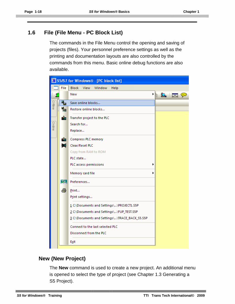
1.6 File (File Menu - PC Block List)
The commands in the File Menu control the opening and saving of projects (files). Your personnel preference settings as well as the printing and documentation layouts are also controlled by the commands from this menu. Basic online debug functions are also available.
New (New Project) The New command is used to create a new project. An additional menu is opened to select the type of project (see Chapter 1.3 Generating a S5 Project).

Chapter 1 S5 for Windows® Basics Page 1-19
TTI Trans Tech International© 2009 S5 for Windows® Training
Save Online Blocks
The PLC Blocks in the connected online PLC can be saved in an archive file (compressed). A dialog box is opened where you can select the Archive Name and the path to save the archived PLC program. This command is used to backup PLC programs and save the different versions (Backup History).
Restore Online Blocks
The archived PLC Programs saved in the PC (different versions – backup History) are listed. The marked archived PLC Program can be transferred to the connected online PLC. This program will replace PLC program inside the PLC.

Page 1-20 S5 for Windows® Basics Chapter 1
S5 for Windows® Training TTI Trans Tech International© 2009
Restore Online Blocks
Transfer Project to the PLC
The PLC Project marked in the “Offline Tree” is transferred to the connected online PLC.
Prior to overwriting a Block a warning is displayed to allow or cancel the overwriting.

Chapter 1 S5 for Windows® Basics Page 1-21
TTI Trans Tech International© 2009 S5 for Windows® Training
Search For
A dialog box is opened providing the tools to search for an operand or text within a PLC Block or within the whole PLC program. This feature works only with the offline S5 project.
The result is shown in the “Search result” window.
Double clicking a line or using the right mouse button will open the editor window displaying the Block and Segment of the selected operand.

Page 1-22 S5 for Windows® Basics Chapter 1
S5 for Windows® Training TTI Trans Tech International© 2009
Replace
A dialog box is opened providing the tools to replace an operand or text within a PLC Block or within the whole PLC program. This feature works only with the offline S5 project.
If “Replace with confirm” is marked a field is open to allow or not each replacement or cancel the replacement completely.
Compress PLC Memory
Deleting blocks in the PLC does not remove these blocks from the PLC memory. The deleted blocks still occupy space in the memory. If blocks with the same name are transferred to the PLC, the old block remains in the PLC and occupies space in the PLC memory. The Compress command, from the PLC menu, reorganizes the PLC memory. All the unused blocks are deleted. After executing this command only usable blocks remain in the PLC memory. The compress function does not work in the RUN mode.

Chapter 1 S5 for Windows® Basics Page 1-23
TTI Trans Tech International© 2009 S5 for Windows® Training
Clear / Reset PLC
Overall Reset; Erasing the Program Memory and Resetting the CPU
Before downloading a new program to the S5 programmable controller (PLC) a memory reset on the CPU should be performed to ensure that no "old" blocks and information are still in the CPU.
Overall Reset deletes the following: • PLC program memory
• All data (flags, S flags, timers and counters)
• All error IDs.
In addition, all system data is automatically assigned default values after “Overall Reset” so that the system data area assumes a defined “basic status”.
The extended system data area (RT) is not deleted.
There are two ways of deleting the internal program memory:
• Offline via the switch for "Default/Overall Reset"
• Online with the "Delete" programmer function.
Click the command “Clear / Reset PLC” in the File menu.
To ensure that the command “Clear / Reset PLC” is not accidentally executed a warning is displayed. Confirm the warning.
If the CPU is not in the Stop mode a message is displayed and the command “Clear / Reset PLC” will not be executed.

Page 1-24 S5 for Windows® Basics Chapter 1
S5 for Windows® Training TTI Trans Tech International© 2009
Copy from RAM to ROM This command is only available with S7 PLC’s,
PLC State
Several online displays are provided to display the status of the PLC.
If the PLC is running only “S5 System Data” and “S5 Memory usage”
If the PLC is in a stop condition, the Interrupt Stack (I-Stack) and the Block Stack (B-Stack) will display the reasons for the stop condition.
Interrupt Stack (I-Stack)
RUN
The PLC is in a RUN condition. Clicking the button puts the PLC into a RUN condition.
STOP
The PLC is in a STOP condition. Clicking the button puts the PLC into a STOP condition.

Chapter 1 S5 for Windows® Basics Page 1-25
TTI Trans Tech International© 2009 S5 for Windows® Training
Register (ACCU's)
The contents of accumulators 1 and 2 are displayed in hexadecimal form. The contents of the additional accumulators, 3 and 4 (certain S5 CPU's only) are displayed in the Extended Interrupt Stack display
Block and Segment
The block and the Segment where the PLC program was interrupted (stop condition) is displayed.
Data Block
If a data block (DB) was active when the PLC program was interrupted, the data block number will be displayed.
Level
Some S5 CPU’s provide different interrupt stack levels. Buttons are provided to switch between the levels of the I-Stack.
Control Bits
A pull down list field is provided to display the control bits in a man-readable form.
Cause of Faults
A pull down list field is provided to display the faults in a man-readable form

Page 1-26 S5 for Windows® Basics Chapter 1
S5 for Windows® Training TTI Trans Tech International© 2009
Portion of Erroneous Block
A pull down list field is provided to display the portion of the PLC where the fault occurred. The statement where the PLC went into a STOP condition is displayed with a blue background.
Extended Display
A button is provided to switch to extended interrupt stack.
Block Stack (B-Stack) During the program execution the jump instructions enter data in the block stack. The block where the jump (block call) originated and the following locations are listed. The block stack lists all the blocks that that were called but had not been completely processed prior to the CPU going into its STOP mode.
Details are displayed about the selected block (segment). Mark the Block that you want details on.
Chapter 1 S5 for Windows® Basics Page 1-27
TTI Trans Tech International© 2009 S5 for Windows® Training
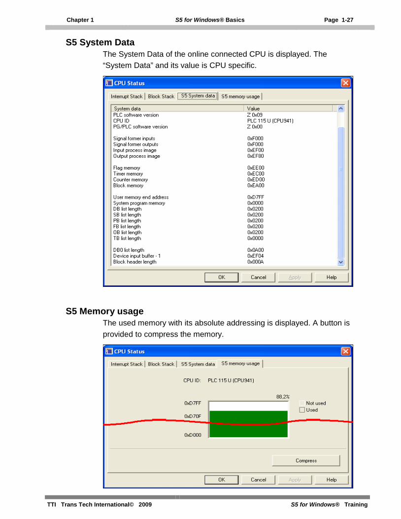
S5 System Data The System Data of the online connected CPU is displayed. The “System Data” and its value is CPU specific.
S5 Memory usage The used memory with its absolute addressing is displayed. A button is provided to compress the memory.

Page 1-28 S5 for Windows® Basics Chapter 1
S5 for Windows® Training TTI Trans Tech International© 2009
S5 Extended Interrupt Stack (Extended display – I-Stack)
Depending on the fault and the type of the S5 CPU, additional information about the fault and the status of the CPU are displayed in the S5 Extended Interrupt Stack.
S5 Extended Interrupt Stack information
Mnemonics Explanation
Depth The nesting level is shown
BEF-REG Statement register
SAZ (new) Step address counter (new)
DB-ADR Data block address
BA-ADR Block address
BST-STP Block stack pointer
Block Block type and number
Level Number of nesting levels
REL-SAZ Relative step address counter

Chapter 1 S5 for Windows® Basics Page 1-29
TTI Trans Tech International© 2009 S5 for Windows® Training
Mnemonics Explanation (continued) DBL-REG Data block register
BS-REG Block register
Tile No. Number of tiles
SAZ (old) Step address counter (old)
UAMK Interrupt display high word
UALW Interrupt display low word
Brackets Nesting stack entry 1 to 6 entered for A( and O(
anz1 0 0 1
anz0 0 1 0
Accu 1=0 or 0 is shifted
Accu 1>0 or 1 is shifted Accu 1<0
ovfl Arithmetic overflow
ovfls Arithmetic overflow latched
or OR memory
erab First scan (negated signal)
stat Status of the operand of the last binary statement executed
ROL Result of logical operation
ACCU 1-4 Contents of the accumulators 1 -4
PLC Access Permission
This command is only available with S7 PLC’s.
PLC Access Permission
This command is only available with S7 PLC’s.

Page 1-30 S5 for Windows® Basics Chapter 1
S5 for Windows® Training TTI Trans Tech International© 2009
Preferences
The Preferences command or clicking the icon opens the Preferences dialog box.
The dialog box is designed as a card file with tabs to separate the different subjects.
Each dialog box card offers buttons and command fields to setup the appearance of S5 for Windows®.
Block View Tab
Mnemonics
The language of the mnemonics you want to use can be set. The selection changes the mnemonics of the instructions (key words) and the operands in the logic and the symbolic table. The selection will not change the language of the program (menu commands, symbols, comments, etc.).

Chapter 1 S5 for Windows® Basics Page 1-31
TTI Trans Tech International© 2009 S5 for Windows® Training
English Mnemonics
The mnemonics to identify Bit-Memory, Timers, Counters, Inputs, Outputs, and the instruction set used for Statement List (STL) programming are identified with their English (International mnemonics) syntax.
Example:
Mnemonics Name English German Input I E
Output Q A
Flag F M
Timer T T
Counter C Z
AND A U
OR O O
Count Down CD ZR
Column Width
S5 for Windows® can display a symbolic operand with up to 24 characters (without a hyphen). To display symbolic operands with their full length name, the column width is adjustable. It is insured, that the operand is correctly identified even when the symbolic name is truncated in the display.
The column width is separately adjustable for the Control System Flowchart (CSF) and the Ladder Diagram (LAD) display. You can select a column width between 10 and 26 characters (including the leading hyphen) for the CSF display. LAD display allows a column width between 12 and 28 characters (including the leading hyphen).
The number entered as the column width is the number of characters spaces possible to display. The width of a character space varies with the font selected and does not always match the width of the other characters. Usually the number of space characters is slightly higher than the number of characters possible to be displayed in a given column width.

Page 1-32 S5 for Windows® Basics Chapter 1
S5 for Windows® Training TTI Trans Tech International© 2009
Column width example S5 for Windows®
Status Values
Address In this column the memory addresses of the S5 instruction is displayed. The address displayed in the STL Status window online is the absolute addresses within the PLC RAM area.
RLO In this column the Result of a Logical Instruction (ROL) of the instruction in that specific line is displayed.
Contents In this column the Status Bit or the Contents of counters and timers is displayed.
ACCU1, ACCU2 In these columns the contents of the Accumulators are displayed. The accumulators are 16 or 32 bit general purpose registers and are used to process bytes, words, and double words.
Status Word In this column the contents of the Status Word is displayed. The eight (8) lower bits of the 16 bit Status Word Register are showing detailed information about the instruction.
Address Register 1, Address Register 2 Only S7 CPU’s have Address Registers.
DB Register 1, DB Register 2 The contents of the Data Block Registers are displayed in these columns. S5 CPU’s only have one (1) Data Block Register.

Chapter 1 S5 for Windows® Basics Page 1-33
TTI Trans Tech International© 2009 S5 for Windows® Training
Indirect Address In this column the information about the indirect addressing in use are displayed (S7 CPU’s only).
Display all Parameters
If selected all formal operands are displayed if calling a Function Block (FB).
Background Color
The default setting is that Windows with “Offline – information” have a light yellow background. Windows with “Online – information” have a light green background.
The color of the background can be changed. Clicking the button will open a dialog box to change the colors.
Note:
The more information you want to display in the STL Status window the longer it takes to build up the STL Status window. All information being displayed has to be transferred from the PLC to the PC.

Page 1-34 S5 for Windows® Basics Chapter 1
S5 for Windows® Training TTI Trans Tech International© 2009
Fonts Tab
The font can be changed. Clicking the button will open a dialog box to change the fonts.
Different fonts may be assigned to various subjects for separation and a better reading. Also the font size and its style may be set.
Note:
The font selection (done via the Presentation Fonts settings) is for the CRT display only. The fonts for the documentation printout are selected with the settings from the Font Type card of the Documentation Layout dialog box.
Chapter 1 S5 for Windows® Basics Page 1-35
TTI Trans Tech International© 2009 S5 for Windows® Training
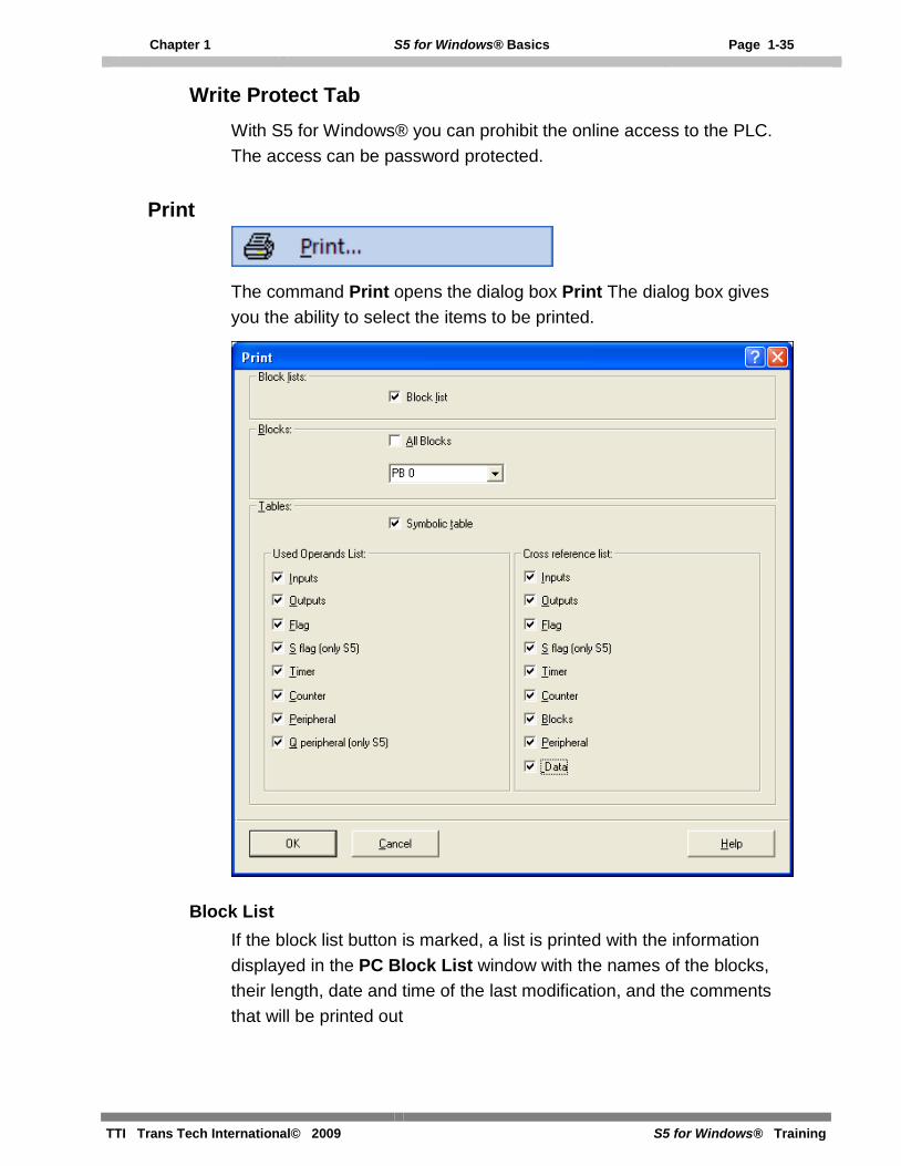
Write Protect Tab With S5 for Windows® you can prohibit the online access to the PLC. The access can be password protected.
The command Print opens the dialog box Print The dialog box gives you the ability to select the items to be printed.
Block List If the block list button is marked, a list is printed with the information displayed in the PC Block List window with the names of the blocks, their length, date and time of the last modification, and the comments that will be printed out

Page 1-36 S5 for Windows® Basics Chapter 1
S5 for Windows® Training TTI Trans Tech International© 2009
Symbolic Table If the symbolic table button is marked, the symbolic table will be printed out.
Used Operands List The portions of the Used Operands List to be printed can be selected. You may mark one, several, or all operand groups to be printed in the used operands list. The used operands list is printed, showing the selected operands and where they are used (block and segment number) within the PLC program.
Cross Reference List The portions of the Cross Reference List to be printed can be selected. You may mark one, several, or all operand groups to be printed the cross- reference list. The cross-reference list is printed showing the selected operands and where they are used (block and segment number) within the PLC program.
Print Settings
The Print Settings command or clicking the icon opens the Documentation Layout dialog box.
The dialog box is designed as a card file with tabs to separate the different subjects.

Chapter 1 S5 for Windows® Basics Page 1-37
TTI Trans Tech International© 2009 S5 for Windows® Training
Margins Tab Select the set margins dialog box to customize the page layout. The margins of the Program Text (Main Body – area where the PLC logic is printed) and the Footer (Header / Footer) are set independently. The dimensions are in centimeters (cm).
The measurements must be entered in centimeter (cm). The margins for the header and the footer are measured relative to
the page. The margins of the main body are measured relative to the header
and footer (inside). Page Layout Margins
The tab provides fields to customize the appearance of the page of documentation for the PLC program.
You may type any text in the text fields. There are field abbreviations available to assist you when entering PLC program information and date and time information to the header and footer. Buttons are available to disable the footer or header. The font for the header and footer may also be set.
Main Body
Header / Footer
Header / Footer
Top
BottonLeft Right
RightLeft
Botton
Top

Page 1-38 S5 for Windows® Basics Chapter 1
S5 for Windows® Training TTI Trans Tech International© 2009
Header / Footer Tab
Font The font can be selected. Clicking the button will open a dialog box to change the fonts.
The font selections made in the Fonts Type settings box, are used for printing only.
Header The tab provides a field (you may enable / disable the header) to customize the appearance of the page header of documentation for the PLC program. You may type any text in the text field.
Footer The tab provides a field (you may enable / disable the footer) to customize the appearance of the page footer of documentation for the PLC program.
There are field abbreviations available to assist you when entering PLC program information and date and time information to the footer. You may type in addition to the abbreviations any text in the text field.

Chapter 1 S5 for Windows® Basics Page 1-39
TTI Trans Tech International© 2009 S5 for Windows® Training
Footer Field abbreviations
%f File name of the PLC program without file name extension.
%t List name (Title).
%p Page number.
%a Day Printing date
%b Month Printing date.
%c Year Printing date.
%d Day File creation/modification date.
%m Month File creation/modification date.
%y Year File creation/modification date.
%h Hour File creation/modification date.
%I Minutes File creation/modification date.
%s Seconds File creation/modification date.
Connect to the last selected PLC
The last selected PLC online connection is established again (how to select and establish an online PLC connection see chapter 2).
Connect to the last selected PLC
The PLC online connection is disabled.

Page 1-40 S5 for Windows® Basics Chapter 1
S5 for Windows® Training TTI Trans Tech International© 2009
Chapter 2 S5 for Windows® Online Functions Page 2-1
TTI Trans Tech International© 2009 S5 for Windows® Training
2 S5 for Windows® Online Functions
How to troubleshoot an On-Line connection to the PLC
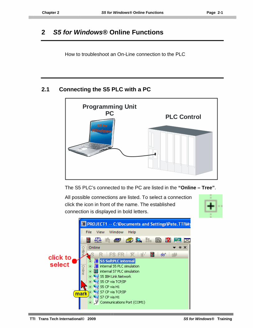
2.1 Connecting the S5 PLC with a PC
Programming UnitPC PLC Control
S5 forWindows
The S5 PLC’s connected to the PC are listed in the “Online – Tree”.
All possible connections are listed. To select a connection click the icon in front of the name. The established connection is displayed in bold letters.

Page 2-2 S5 for Windows® Online Functions Chapter 2
S5 for Windows® Training TTI Trans Tech International© 2009
If the “Online” tab is not shown, use the command “Online tree” from the “File” menu.
It is recommended that you use the “Auto Hide” icon to lock the tab at the outside border of S5 for Windows®. By moving the mouse pointer to the tab, the window will automatically open.
S5 SoftPLC internal
On the PC executing S5 for Windows®, an S5 SoftPLC can be installed (optional). This software PLC could be used to control machinery. Inputs and outputs are handled via a bus system (Profi Bus etc.)
Internal S5 PLC Simulation
S5 for Windows® provides an internal simulation PLC. With the integrated simulation PLC you can test PLC programs. For testing you do not need additional hardware. The programs are tested directly within your PC. The status is displayed, you can force inputs, and you can display the outputs.
The internal simulation PLC is fully compatible with the S5 CPU 945.

Chapter 2 S5 for Windows® Online Functions Page 2-3
TTI Trans Tech International© 2009 S5 for Windows® Training
S5 IBH Link Network
The IBHLink S5 is an Ethernet-converter within a 15-pin Sub-D-housing for a connection via a switch, a hub or even directly to a PC with a common network adaptor. The protocol used is the standard TCP/IP protocol. In this way, the user can benefit from all the advantages of Ethernet, such as remote maintenance via a standard router or VPN-connections (Virtual Private Network). Likewise, a direct connection to the Internet is possible.
S5 CP via TCP/IP; S5 CP via H1
These connections require “Communication Processer Boards” in the PLC. The connections are listed because a standard Ethernet connection is required at the PC side.
Communication Port (COM1)
Selecting the Communications serial ports (COM 1 – COM 4) will open a dialog box to select the Baud Rate and the Protocol.

Page 2-4 S5 for Windows® Online Functions Chapter 2
S5 for Windows® Training TTI Trans Tech International© 2009
The Simatic S5 PLC must be connected to one of the serial ports (COM 1 – COM 4) of your PC via a 20mA current loop converter. Select the AS511 (Simatic-S5) protocol for the communication.
The Simatic S5 can only handle a Baud Rate of 9600 Baud. S5 for Windows® allows you to select higher baud rates for the communication with other compatible PLC's.
USB Serial Port (COM3)
S5 for Windows® cannot handle an USB Port connection directly. To use an USB connector cable, software must be installed to convert the COM port connection to an USB port. This software driver is provider with the USB cable. The following pictures show the correct settings of the USB Serial Port conversion. Double click “USB Serial Port (COM3) to open the dialog to set the port parameters.

Chapter 2 S5 for Windows® Online Functions Page 2-5
TTI Trans Tech International© 2009 S5 for Windows® Training
Device Manager Settings (USB – COM conversion)

Page 2-6 S5 for Windows® Online Functions Chapter 2
S5 for Windows® Training TTI Trans Tech International© 2009
2.2 Transferring all PLC Blocks of a STEP® 5 / S5W Project to the PLC
The PLC Blocks of a STEP® 5 / S5W Project can be directly transferred to the connected PLC. No conversion is necessary.
Transferring a STEP® 5 Project to the PLC The following icon identifies a STEP® 5 Project. PLC projects (programs) created with the basic PLC programming package STEP® 5 from SIEMENS with a DOS operating system (or S5-DOS) may directly be transferred to the PLC.
Open the “Offline – Tree” and click the project name with the right mouse button. Click “Transfer to PLC” in the context menu.
The PLC project, with all the PLC Blocks, is transferred to the connected PLC.
Note:
If your PLC projects (programs) have been created with one of the following SIEMENS programming units (PU), PG-685, PG-675 or PG-635 in CPM, they must be converted to a DOS disk format.
The converted projects may be used directly by S5 for Windows®. No conversion is necessary but recommended.

Chapter 2 S5 for Windows® Online Functions Page 2-7
TTI Trans Tech International© 2009 S5 for Windows® Training
Transferring a S5W Project to the PLC The following icon identifies a S5W Project.
Open the “Offline – Tree” and click the project name with the right mouse button. Click “Transfer to PLC” in the context menu.
The PLC project, with all the PLC Blocks, is transferred to the connected PLC. If a block is currently stored in the PLC, a dialog box will open to allow you to overwrite the block or to abort the transfer.
Activating the Yes button will only overwrite the PLC block mentioned in the dialog box. If another block is stored in the PLC, the dialog box will be opened again.

Page 2-8 S5 for Windows® Online Functions Chapter 2
S5 for Windows® Training TTI Trans Tech International© 2009
2.3 Transferring a PLC Program or PLC Blocks to the PC
To transfer Blocks from the PLC to the PC, an S5 project must be available in the PC to store the transferred Blocks. The project must be selected prior transferring Blocks to the PC.
A single Block, several Blocks or all Blocks can be transferred via the serial link to the PC. The selected (marked) blocks in the PLC block list are transferred to the PC. This can be a single block or multiple blocks.
Select the Project to save the PLC Program
Make sure the PC Block List is empty.
Warning:
You should only transfer blocks from the PLC to the PC if the selected blocks do not exist in the PC Block List.
If a block in the PC is overwritten by a PLC block, it is possible that comments will be shifted. Jumps may not be valid anymore and jump labels may be exchanged with substitute labels (M001 etc.) and shifted.

Chapter 2 S5 for Windows® Online Functions Page 2-9
TTI Trans Tech International© 2009 S5 for Windows® Training
Open the PLC Block List
If you want to transfer one or several blocks to the PC, mark these blocks in the PLC Block List and click on one of the marked Blocks with the right mouse button. Click “Transfer to PC”.
Instead of using the right mouse button and the command “Transfer to PC” you may use the “Transfer to PC” icon.

Page 2-10 S5 for Windows® Online Functions Chapter 2
S5 for Windows® Training TTI Trans Tech International© 2009
The marked Blocks are transferred to the PC and are listed in the “PC Block List”.
To transfer all PLC Blocks from the PLC to the PC, use the command “Transfer all blocks to PC”. Click on one of the marked Blocks with the right mouse button. Click “Transfer all blocks to PC”.
All Blocks from the PLC are transferred to the PC and are listed in the “PC Block List”.

Chapter 3 S5 for Windows® Tools to Debug a S5 PLC Program Page 3-1
TTI Trans Tech International© 2009 S5 for Windows® Training
3 S5 for Windows® Tools to Debug a S5 PLC Program
Most tools to debug a S5 PLC Program can only be used if the PLC Program is present in the online PLC, and also saved in a S5 Project on the PC.
3.1 Opening a S5 PLC Program saved in a “S5 Project”
Open the “Offline – Tree” by pointing at the “Offline” tab.
If the “Offline” tab is not shown, use the command “Offline tree” from the “File” menu.
ATTENTION:
If you don’t have the original PLC program with symbols and comments we recommend that you download the PLC program to the PC as described in chapter 2.

Page 3-2 S5 for Windows® Tools to Debug a S5 PLC Program Chapter 3
S5 for Windows® Training TTI Trans Tech International© 2009
In the “Offline” window select the path and click on the icon in front of the project name (PROJECT1.S5P).
The project files and other tools are shown.
The project name, with its path is shown. Also the Blocks are listed in the “PC Block List”.
The PLC Program is now open for further use.
Chapter 3 S5 for Windows® Tools to Debug a S5 PLC Program Page 3-3
TTI Trans Tech International© 2009 S5 for Windows® Training
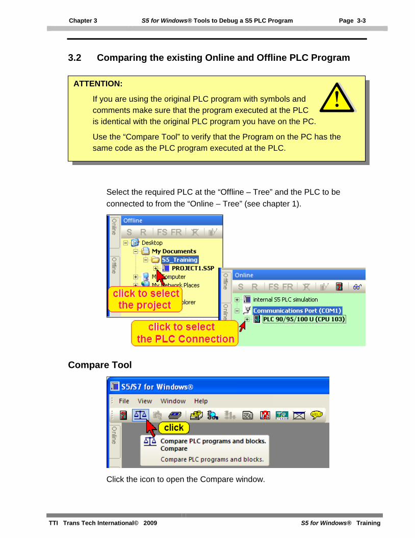
3.2 Comparing the existing Online and Offline PLC Program
Select the required PLC at the “Offline – Tree” and the PLC to be connected to from the “Online – Tree” (see chapter 1).
Compare Tool
Click the icon to open the Compare window.
ATTENTION:
If you are using the original PLC program with symbols and comments make sure that the program executed at the PLC is identical with the original PLC program you have on the PC.
Use the “Compare Tool” to verify that the Program on the PC has the same code as the PLC program executed at the PLC.

Page 3-4 S5 for Windows® Tools to Debug a S5 PLC Program Chapter 3
S5 for Windows® Training TTI Trans Tech International© 2009
You may select the two locations where the files to be compared are located.
When comparing a PLC Program on the PC with the Program executed on the PLC, only the code is relevant. Mark “Compare code only”. To start the comparison confirm by clicking the “Compare” button.
The compare result is shown in the upper part of the compare window. PLC Block names written in black are identical, PLC Block names shown in red have differences in the code.
ATTENTION:
Do not transfer blocks from the PLC to the PC if the selected blocks exist in the PC RAM. If a block in the PC is overwritten by a PLC block, it is possible that comments will be shifted and labels may not be valid anymore (labels are exchanged with substitute labels (M001 etc.).

Chapter 3 S5 for Windows® Tools to Debug a S5 PLC Program Page 3-5
TTI Trans Tech International© 2009 S5 for Windows® Training
Differences in Code
Clicking the Block name opens a window with the details of the compared Blocks. Any differences are displayed in red.
ATTENTION:
Comparing a PLC Program on the PC with the Program executed on the PLC will show (most of the time) differences in Data Blocks (DBxx). This is normal if the data stored in the Data Block is collected from the PLC.
In any event the length of the Data Blocks must be identical.

Page 3-6 S5 for Windows® Tools to Debug a S5 PLC Program Chapter 3
S5 for Windows® Training TTI Trans Tech International© 2009
3.3 Arranging Window in the Workplace
Version 6.x of S5 for Windows® has a new concept to open and close windows in the workplace.
You can use the “Auto Hide” icon to lock the tab at the outside border of the workplace and by moving the mouse pointer to the tab the window will open automatically.
It is also possible to open the “PC Block List” in the workplace and start the “Debug Tools” from there. The “PC Block List” window stays open until you close “PC Block List” the window.
This mode is preferable if you want to change between Blocks being displayed online and offline for modifications.
To work in this “Classic Operator Interface” mode the S5 PLC Program must be opened (see chapter 3.1).
To select the previously described mode, click “Classic operator interface” in the “Window” menu.
PC Block List in “Classic Operator Interface” mode

Chapter 3 S5 for Windows® Tools to Debug a S5 PLC Program Page 3-7
TTI Trans Tech International© 2009 S5 for Windows® Training
3.4 PLC Block Status display
To display the PLC status you must open the desired PLC Block with the “Editor”. You may open the Editor by double clicking the Block name or by marking the Block name and clicking the icon.
The Block may be selected from the “PC Block List” or the “PLC Block List”. If you use the “PC Block List” existing symbolic comments may be displayed within the status display.
Activating the Status An icon is provided to activate the status. Clicking the icon again will deactivate the status.
Note:
We recommend that you select the Block from the “PC Block List”. If any modifications are made they are saved in the PC and therefore are available the next time the Block is opened.
Page 3-8 S5 for Windows® Tools to Debug a S5 PLC Program Chapter 3
S5 for Windows® Training TTI Trans Tech International© 2009
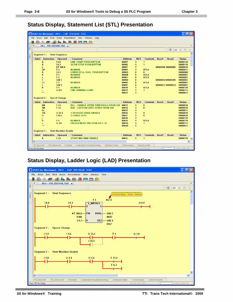
Status Display, Statement List (STL) Presentation
Status Display, Ladder Logic (LAD) Presentation

Chapter 3 S5 for Windows® Tools to Debug a S5 PLC Program Page 3-9
TTI Trans Tech International© 2009 S5 for Windows® Training
Status Display, Ladder Logic (LAD) Presentation with Symbolic Table
Status Display, Control System Flowchart (CSF) Presentation

Page 3-10 S5 for Windows® Tools to Debug a S5 PLC Program Chapter 3
S5 for Windows® Training TTI Trans Tech International© 2009