1 proposal for a multi-optical transition radiation system in atf2 a. faus-golfe, d. mccormick ific...
TRANSCRIPT

1
Proposal for a Multi-Optical Proposal for a Multi-Optical Transition Radiation System Transition Radiation System
in ATF2in ATF2
A. Faus-Golfe, D. McCormickIFIC – SLAC
11 June 2009 8th TB/SGC Meeting

2
Motivation and ObjectivesMotivation and Objectives
- We propose to install a series of four Optical Transition Radiation (OTR) monitors in the beam diagnostic section of the EXT line of ATF, close to the multi wire scanner system.
-The system would be a valuable tool for measuring beam sizes and emittances from the ATF DR.
- An original OTR design demonstrated the ability to measure a 5.5 um beam size in one beam pulse and to take many fast measurement.

3
PROPOSAL: Multi OTR System (4 units)
(collaboration involving SLAC and IFIC, with the KEK support):
beam dynamics studies, design, construction, and characterization including associated electronics
- Horizontal and vertical beam size measurement in one beam pulse with 2 um resolution- OTR’s placed close to the wire scanners: definitive test of OTR as emittance diagnostic device.
New Multi-OTR SystemNew Multi-OTR SystemIn the diagnostic section of the ATF EXT line 5 wire scanners are located to allow emittance measurements (with 10 um tungsten and 7 um carbon wires)
- Requires many machine pulses, slow measurements- Resolution: less than 2 um in X and 0.3 um in Y

4
New design of the OTR for ATF-ATF2
Existing OTR monitor (OTR1X)Existing OTR monitor (OTR1X)
4
The OTR1X monitor is installed in the ATF2 EXT line after the septum magnets.
It has been used to study the relation between the beam trajectory and the emittance growth due to non-linear fields in the extraction process
open the bumpin DR and EXT
close the bump in the DR OTR monitor
Measured beam sizes on 19th Dec’07
CCD camera
Inferred emittances from modeled ß-functions and dispersions

5
New design of the OTR for ATF-ATF2
Current OTR setupCurrent OTR setup
Current OTR installed in the ATF EXT line
target
CCD camera
Space required for current OTR
• The OTR1X was an evolved design rather than a optimized one. – New parts were added to the existing OTR to add functionality. Instead of
making new design they were added bit by bit. • As a result the OTR1X is a patchwork of parts and takes up a lot of beam line
space. • Existing OTR targets were rather thick, about 0.5mm of copper, beryllium or
glassy carbon. This caused radiation darkening of the glass lens and camera damage.
• The camera CCD was not parallel to the target. This meant that the beam spot was in focus on only a small portion of the target. If the beam moved, the image had to be refocused.

6
- Target actuator relocated to the top (no interference with the girder) and smaller design greater flexibility in the OTR placement
- Thinner target reduce lens radiation darkening
- CCD camera parallel to the target. This will put the entire target into focus and reduce the need to adjust focus during normal operation greater depth of field.
- 12 bit camera for more dynamic range with smaller pixel size for more resolution.
- The extreme thinness of the aluminum’s 1200 Angstroms will reduce the power deposition in the aluminum and coupled to larger beam spot sizes should eliminate target damage problems.
New OTRs will have same controls and motion capabilities as current OTR with the following improvements:
New OTR monitor designNew OTR monitor design

7
Optics and location for the new OTR’sOptics and location for the new OTR’s

8
Optics and location for the new OTR’sOptics and location for the new OTR’s
MAD Twiss parameters and beam size calculations for OTR1X and MW0X-MW4X of the ATF EXT line optics (V4.1)
OTR1X_old
Start EXT
OTR1X MW0X MW1X MW2X MW3X MW4X
x [nm.rad] 2.0
y [pm.rad] 12
E 8.00 x10⁻⁴
x [m] 8.267 6.853 7.392 3.282 12.122 3.824 11.412 3.758
y [m] 5.227 2.941 5.617 9.271 4.496 13.790 3.527 9.702
Dx [m] 0.389 0.000 0.436 0.000 0.000 0.000 0.000 0.000
Dy [m] 0.000 0.000 0.000 0.000 0.000 0.000 0.000 0.000
x [2] 0.114 0.000 0.122 2.875 2.905 2.983 3.103 3.184
x [2] 0.000 2.752 0.030 0.078 0.120 0.080
y [2] 0.356 0.0000 0.366 2.142 2.184 2.251 2.363 2.455
y [2] 0.0000 1.775 0.042 0.067 0.112 0.092
x [m] 439.78 117.07 470.10 81.02 155.71 87.45 151.08 86.69
y [m] 7.85 5.89 8.14 10.46 7.28 12.75 6.45 10.70
The four OTR’s have to be as close as possible to the wire scanners in order to have similar conditions.

9
Optics and location for the new OTR’sOptics and location for the new OTR’s
Input parameters:50.000 particlesx, y and E gaussian distribution
Beam sizes, ß-functions and emittances for OTR1X and MW0X-MW4X of the ATF EXT line optics calculated from tracking simulations using PLACET and MAD programs.
OTR1X_old
OTR1X MW0X MW1X MW2X MW3X MW4X
x [m] 337.41 370.39 81.73 157.06 88.00 151.31 86.87
y [m] 7.24 8.13 10.57 7.36 12.83 6.44 10.69
x [nm.rad] 2.02 2.02 2.02 2.02 2.02
y [pm.rad] 1.18 1.18 1.19 1.19 1.19 1.19 1.19
x [m] 3.305 12.212 3.834 11.131 3.735
y [m] 4.435 5.588 9.398 4.551 13.841 3.484 9.603
Spot sizes estimated for the new OTR locations are a bit larger than the spots that damaged the cooper target in the original OTR tests no target damage expected

10
Beam plotsBeam plotsy vs x x’ vs x y’ vs y
OTR1X
MW0X
MW1X

11
Beam plotsBeam plotsx’ vs x
MW2X
MW3X
MW4X
y vs x y’ vs y

12
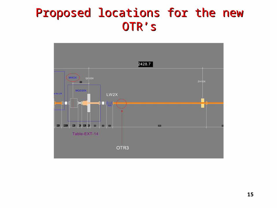
Proposed locations for the new OTR’sProposed locations for the new OTR’s
In order to make the validation tests of the OTR as a beam emittance diagnostic device, the proposed locations of the four OTR’s are as close as possible to the five wire scanners.
A length of about 300 mm will be needed for each OTR unit.

13
Proposed locations for the new OTR’sProposed locations for the new OTR’s

14
Proposed locations for the new OTR’sProposed locations for the new OTR’s
15
Proposed locations for the new OTR’sProposed locations for the new OTR’s

16
Proposed locations for the new OTR’sProposed locations for the new OTR’s

17
ManpowerManpower
The team is a collaborative effort between the IFIC and SLAC.
The people involved are:
IFIC - A. Faus-Golfe, J. Alabau Gonzalvo, M. Alabau Pons, J. V. Civera Navarrete, C. Blanch Gutierrez and J. J. García Garrigós
SLAC - D. McCormick, J. Nelson, B. McKee and J. Cruz

18
Status and planningStatus and planning
-The OTR design is essentially finished.
- The first step will be the mechanical construction of the different parts and the procurement of the optical components, followed by the assembly and the calibration tests.
- The system could be installed by the end of 2009 or later.
- The commissioning could be done immediately after the units have been installed if there is beam time available for calibration.