1. preamble 1.1 1.1.1 general 1.1.2 inclusive documents specificatio… · a. part -1 : general...
TRANSCRIPT

Development of DIMTS Office at 8th Floor, DMRC IT Park, Shastri Park, Delhi Technical Specifications
- 1 -
Technical Specifications
1. PREAMBLE
1.1 The Technical specification Contained herein shall be read in conjunction with the other
Bidding Documents.
1.1.1 General
The Technical specifications covering the material and the workmanship aspects are included
in this section. These specifications cover the items of civil and non-civil works coming under
scope of this work. All work shall be carried out in conformity with the same. These
specifications are not intended to cover the minute details. The work shall be executed in
accordance with good practices followed for achieving high standards of workmanship, thus
ensuring safety and durability of the construction. All codes and standards referred to in these
specifications shall be the latest thereof, unless otherwise stated.
1.1.2 Inclusive Documents
The provisions of special conditions of contract, those specified elsewhere in the bid document,
as well as bid drawings and notes, or other specifications issued in writing by DIMTS shall form
part of the technical specification of this project.
1.1.3 The works shall be executed as per Bill of Quantities & drawings read in conjunction with
technical specifications. In case of any difference/discrepancy in the provisions in BOQ &
technical specifications, the decision of DIMTS/Engineer-in-Charge in the matter shall be final
& binding on contractor.
1.1.4 The attention of the contractor is drawn to those clauses of specifications/relevant codes which
require supporting specification either by the DIMTS or by ‘Mutual’ agreement between the
‘supplier and purchaser’. In such cases, it is the responsibility of the bidder/contractor to seek
clarification on any uncertainty and obtain prior approval of DIMTS before taking up the
supply/construction. In absence of such prior clarification, the DIMTS’ choice/design will be the
final and binding on the contractor without involving separately any additional payment.
1.1.5 The rates of different items of work in the BOQ shall be for all height/ leads/lifts and should
there be any detail of construction or material which has not been referred to in the Specification
or in the Bill of quantities and Drawings but the necessity for which may be implied or inferred
there from, or which is usual or essential to the completion of the work , the same shall be
deemed to be included in the rates and prices entered by the contractor in the Bill of
Quantities(e.g. the installation or fixing of any component of work shall include all necessary
fixtures/hangers/fasteners etc. required for the installation).
1.1.6 The various materials to be used in the works shall be as per the makes/models included in the
list of approved materials included as part of these technical specifications. Only in the specific
case of non-availability of any material as per the list of approved makes, use of substitute
make shall be allowed provided the contractor submits the detail of material accompanied by

Development of DIMTS Office at 8th Floor, DMRC IT Park, Shastri Park, Delhi Technical Specifications
- 2 -
all technical data, sizes, particulars of material, manufacturer’s name/detail etc. to
DIMTS/Engineer-in-Charge and takes prior written approval.
1.1.7 The materials to be used in the works shall confirm to the relevant BIS codes and should be
marked as such. In case of non-availability of BIS specifications for any material, the material
shall confirm to the relevant international standards/codes as per the general industry practice
& as per the requirements of technical specifications.
1.1.7 SAMPLE, SUBMISSION AND APPROVAL : After award of work to the contractor, the contractor shall submit the samples of the various materials/fixtures for approval from DIMTS/Enginner-in –Charge for approval before use in the works .It shall be the responsibility of the Contractor to get the samples approved in due course of time without in any way affecting the overall schedule of completion of works.
1.1.8 Defective Works
All the defective works are liable to be demolished, rebuilt and defective materials replaced by
the contractor at his own cost. In the event of such works being accepted by carrying out repairs
etc., as specified by the DIMTS, The cost of repairs will be borne by the contractor.
1.1.9 General Scope of Work and Site Information
The general scope of work and site information is enclosed as Annexure-I of technical
specifications. The site information given in the bid document is given in good faith by the
‘DIMTS’ but the ‘Contractor’ shall satisfy himself regarding all aspects of the conditions and no
claim will be entertained on the plea that the information supplied by the DIMTS is erroneous
or insufficient.
2 Technical Specifications
2.1 The work shall be executed as per the description of item, approved drawings & design and
technical specifications read in conjunction. The Technical Specifications, in accordance with
which the entire work described hereinafter shall be constructed and completed by the
Contractor, shall comprise of the following :
A. Part -1 : General Technical Specifications : Latest editions of CPWD Specifications Vol-I & II, 2009 along with other Addendum/Corrigendum/Revisions issued/effected upto the last date of receipt of bid
Latest editions of CPWD General Specifications for Electrical Works Part I - Internal and Part II - External - 2005 along with other Addendum/Corrigendum/Revisions issued/effected upto the last date of receipt of bid.
B. Part -2 : Supplementary Technical Specifications: The Supplementary Technical comprise technical specifications supplementing the general technical specifications or specifications not covered in general technical specifications. In case of conflict between general & supplementary technical specifications, the provisions of supplementary technical specifications shall prevail over general technical specifications.
In the absence of any definite provision on any particular issue in the Specifications, the work shall be carried out in accordance with Special Specifications to be prepared by Contractor and approved by DIMTS. Such Special Specification shall be based on technical literature

Development of DIMTS Office at 8th Floor, DMRC IT Park, Shastri Park, Delhi Technical Specifications
- 3 -
comprising national (IRC and IS) and international specifications and good Engineering practice. In case of any dispute, the decision of the DIMTS shall be final and binding on the Contractor.
B.1 : Supplementary Technical Specifications for Electrical works, Firefighting works, FDA
system, Access Control system, CCTV system, PA system, IT networking/structured
cabling, UPS system :
B.1.1 GENERAL
1. DETAIL DRAWINGS FOR SERVICES
After the work is awarded to the contractor, the contractor shall prepare & submit the Detail
design and drawings for various components of works i.e. Electrical conduit/ cabling/ raceway,
cable tray , DB’s, Lighting layout, Power, HVAC ducting, CCTV, UPS, PA system, IT
networking/Data layout, Fire Alarm, Firefighting piping, for approval from the Engineer-in-
Charge.
2 AS BUILT DRAWINGS As part of the handing over documents after successful completion of the work, the Contractor shall
submit to DIMTS “AS BUILT DRAWINGS” drawn at approved scale indicating the complete Electrical & other systems "As installed". These drawings shall be prepared in Autocad 14 or 2000. These drawings shall in particular, give the following information:
a. Routing of Conduits, Raceways, Sub main conduiting, Cable Trays, and Earthing
strips/wires. b. Lighting and Power layouts showing circuit numbers for each light fixture, and socket along
with location of DB’s, Panels etc. Power layout shall also show data/voice outlets and routing of conduits/raceways upto Hub room/Server room as applicable.
c. DB charts showing details of all circuits, phase wise distribution along with total load in each
phase ,incoming wire/cable size etc. d. G.A. drawing of all the Panels along with schematic drawings. This shall be incidental to work and nothing extra shall be paid to the Contractor for the same.
3 STATUTORY APPROVALS After the work is completed it is the responsibility of the contractor to get the Electrical/Fire
Fighting/Fire Alarm installations inspected and approved by the Local Authorities concerned, wherever required. Nothing extra shall be payable for the same. If any modification is required to be carried out as per the comments of local authorities it shall be carried out by Electrical Contractor at no extra cost. Required statutory approvals is included in the scope of work at no extra charge. All required liasioning work is included in scope of work and nothing extra is payable.
4 OPERATION AND MAINTENANCE MANUALS As part of the handing over documents, the Contractor shall submit to DIMTS/ Engineer-in-Charge 3
copies of comprehensive operating and maintenance manuals, maintenance schedule and log sheets for all systems and equipment included in this contract. These shall be supported with the manufacturer’s operating and maintenance manuals.
The manuals shall contain basis of design, detailed technical data and drawings for each equipment
as installed, the erection, testing, operation and maintenance procedures, spare parts manual and recommended spares for 3 year period of maintenance of each equipment.

Development of DIMTS Office at 8th Floor, DMRC IT Park, Shastri Park, Delhi Technical Specifications
- 4 -
The Contractor shall also submit the Preventive maintenance schedule for the equipment supplied. 5 TRAINING OF DIMTS’ PERSONNEL The Contractor shall train DIMTS’ Personnel to operate the equipment installed, to carry out routine
maintenance work including lubrication, overhauling, adjustments, testing, minor repairs and replacement. Nothing extra shall be payable for the same.
Training shall be done before the expiry of the defects liability period. The period of training shall be
mutually agreed upon by DIMTS and Contractor. 6 DIMTS reserves the right to inspect any equipment/material to be supplied by the contractor as part
of his scope of work, at manufacturer’s works. The Contractor shall provide and secure for the Owner’s Authorized Representative every reasonable access and facility at the manufacturer works for inspection and testing.
B.1.2 SPECIFICATIONS FOR ELECTRICAL WORKS, FIREFIGHTING WORKS, FDA SYSTEM,
ACCESS CONTROL SYSTEM, CCTV SYSTEM, PA SYSTEM, IT NETWORKING/STRUCTURED CABLING, UPS SYSTEM
B.1.2.1 CONDUITING AND WIRING 1. GENERAL The system of wiring shall consist of single-core/multi-core PVC insulated Copper conductor FRLS wires in
Metallic conduits concealed/exposed or Raceways as called for. 2. CHECKING OF DRAWINGS Before commencing the conduiting work, the Contractor shall carefully examine the drawings indicating the
layout of conduits, check the number and size of conduits with respect to number of wires , location of junction boxes, sizes and location of switch boxes and other relevant details. Any changes suggested by the Contractor shall be got approved from the Consultants before the actual laying of conduits. Any discrepancy found in the drawings shall be brought to the notice of the Architects/ Consultants promptly before execution of the work.
3. MATERIAL Conduits shall be black enameled mild steel(ISI marked) and be solid drawn or lap welded conduits, stove
enameled inside and outside with minimum wall thickness of 1.6 mm for conduits upto 25 mm diameter and 2 mm wall thickness for conduits above 25 mm diameter. The conduits shall be delivered to the site in original bundles and each length of conduit shall bear the label of the manufacturer. The number of insulated copper conductor wires that may be drawn in the conduits of various sizes are given below and the conduit fill shall not exceed 40%. The minimum size of conduits shall be 25mm diameter for lighting and outlets and conduit size shall be increased as per relevant IS code depending on the number of wires. Wires shall be PVC insulated copper conductor and ISI marked.
4. CONDUIT FILL :- The maximum number of 650/1100 Volts grade single core PVC insulated copper conductor wires that
may be drawn in the conduits of various sizes are given below. Size of wire Size of Conduit (MS) -------------------------------------------------------------------------------------------------------- Area of the wire 25 32 40 50 Sq. mm (Number of wires maximum) --------------------------------------------------------------------------------------------------------

Development of DIMTS Office at 8th Floor, DMRC IT Park, Shastri Park, Delhi Technical Specifications
- 5 -
1.5 10 14 - - 2.5 8 12 - - 4.0 6 10 14 - 6.0 5 8 11 - 10.0 4 7 9 - 16.0 2 4 5 12 25.0 - 2 2 6 35.0 - - 2 5 5. CONDUIT CONNECTIONS:- The threads of pipe and sockets shall be free from grease and oil and shall be thoroughly cleaned before
making the screwed joints. All joints shall be fully water tight. Junction boxes and running joints shall be provided at suitable places to allow for subsequent extension if any, without undue dismantling of conduit system. As far as possible, diagonal run of conduits and adaptable boxes, back outlet boxes, switch boxes and the like must be provided with entry spouts and smooth rubber bushes. Joint between conduit and iron clad distribution boards and control gear shall be effected by means of conduit couplers into each of which will be coupled smooth rubber bushes from the inside of box or case.
Conduit system shall be vertical and straight as far as possible. Traps where water may accumulate from
condensation shall be avoided, however if it is unavoidable suitable provision for draining the water shall be made. Separate conduits shall be run for lighting and 15 amps power outlet wiring. Wires belonging to different phases shall no be run in the same conduit. For every phase wire a separate neutral wire shall be run. Conduits connections for MS conduits shall be screwed metal to metal and be painted with one coat of self etching zinc chromate primer and two coats of enamel paint. The threads and sockets shall be free from grease and oil. Connections between screwed conduit and sheet metal boxes shall be by means of a rubber bush. The joints in conduits shall be free of burrs to avoid damage to insulation of conductors while pulling them through the conduit. External conduits ( exposed to elements ) should be insulated through clamp and water tight fitting.
6. BENDS IN CONDUIT:- Where necessary, bends may be carried out by means of conduit bends and/or circular inspection boxes
with adequate and suitable inlet and outlet screwed joints. In case of recessed system, each junction box shall be provided with a cover properly secured and flushed with the finished wall/ceiling surface, so that the conductors inside the conduit are accessible. No bends shall have radius less than 2.5 times the outside diameter of the conduit. Special spring may be used for bending the conduit. Heating to soften the conduit for bending is not allowed.
7. FIXING OF CONDUITS Conduits and junction boxes shall be kept in position with the help of proper hold fasts while the walls, slabs
and floor are under construction. Fixing of standard bends or elbows shall be avoided as far as practicable and all curves maintained by bending the conduit pipe itself with a ling radius which will permit easy drawing of conductors. All threaded joints of conduit pipes shall be treated with approved preservative compound to secure protection against rust. Conduits shall be arranged so as to facilitate easy drawing of wires through them. Adequate no. of junction boxes shall be provided. All conduits shall be installed away from steam and hot water pipes. After the conduits, junction boxes, outlet boxes and switch boxes are installed in position, their openings shall be properly plugged or covered, so that, water, mortar, insects or any other foreign matter does not enter into the conduit system. Where called for, surface conduits shall be fixed by means of spacer bar saddles at intervals not more than 500 mm from both sides of fittings or accessories. The staples or saddles of galvanished mild steel flat, properly treated, shall be secured and fixed by means
Development of DIMTS Office at 8th Floor, DMRC IT Park, Shastri Park, Delhi Technical Specifications
- 6 -
of nuts and bolts/rawl plugs and brass machine screws at 600 mm intervals. Cutting of horizontal chases shall be avoided. Fixing of standard bends or elbows shall as far as possible, be avoided.
8. CHASE IN THE WALL The chase in the wall shall be neatly made and shall be of ample dimensions to facilitate the recessing of
conduit and flushing with cement plaster. All these shall invariably be done during the construction stages itself, as otherwise breaking and flushing to the original finish may not be practicable at subsequent stages.
9. EXPANSION JOINTS When crossing through expansion joints in the buildings, the conduit sections across the joints shall be
jointed through flexible conduits (non metallic) of the same size as rigid conduits. Alternatively, the two sections shall be jointed by means of over sized conduit lengths with over lapping on both ends. The gaps in between the two pipes shall be suitably, cemented to prevent the ingress of moisture. In addition, it shall technically be a desirable arrangement to provide MS boxes of suitable size at both ends for termination of PVC conduits and jointing through flexible (non metallic) conduits.
10. PROTECTION To minimize condensation or sweating inside the conduit pipes, all outlets of conduit system shall be
adequately ventilated. All socketed connections shall be made fully water tight by use of proper jointing compound.
11. SWITCH – OUTLET AND JUNCTION BOXES All outlets for switch and other receptacles shall be equipped with rust proof outlet boxes of MS as called
for, having external and internal surface true to finish. Where called for, outlet boxes for receiving switches shall be fabricated to approved sizes and covered with approved White Polycarbonate modular cover plate. All boxes shall have adequate number of knock- out holes of required diameter and an earthing terminal screw. The junction boxes and switch/socket outlet boxes shall be provided with approved White Polycorbonate modular cover plate secured to the box with brass countersunk screws. Outlets exposed to the weather shall be fully water tight, complete with rubber gasketed covers. The outlet boxes shall be painted with two coats of bituminous paint before they are fixed in position. Outlet boxes fixed in concrete shall be of a minimum depth of 75 mm and the wall thickness of the boxes and spouts shall not be less than 2mm. Outlet boxes fixed in wall shall be of a minimum depth of 50 mm and the wall thickness of the boxes and spouts shall not be less than 18 guage.
12. INSPECTION BOXES Rust proof inspection boxes of cast iron and of required size, having smooth external and internal finish shall
be provided to permit periodical inspection and to facilitate removal and replacement of wires when required. Inspection boxes shall be mounted flush with ceiling/finished wall surface and shall be provided with screwed cover of 1.5 mm thick M.S. Cover plate secured to the box with brass screws. Adequate holes shall be provided for ventilation in inspection box covers. The minimum size of inspection boxes shall be 75 mm x 75 mm.
13. TELEPHONE/COMPUTER SYSTEM Conduits, junction boxes, draw boxes, outlet boxes and covers for telephone/ computer system shall be as
described under relevant clauses of the specifications. Conduits for telephone/computer system shall be atleast 300 mm away from the electrical conduits. The conduits for telephone/computer wiring shall be of specified size and shall terminate at outlets, as indicated on the drawings.
14. BUNCHING OF WIRES Wires carrying current shall be so bunched in the conduit that the outgoing and return cables are drawn into
the same conduit. Cables originating from two different phases shall not run in the same conduit. 15. DRAWING CONDUCTORS

Development of DIMTS Office at 8th Floor, DMRC IT Park, Shastri Park, Delhi Technical Specifications
- 7 -
The drawing and jointing of copper conductor wires and cables shall be executed with due care so as to
avoid any damage to the wire. While drawing insulated wires into the conduit, care shall be taken to avoid scratches and kinks which cause breakage of conductor. There shall be no sharp bends. Insulation shall be shaved off like sharpening of a pencil, and it shall not be removed by cutting it across the wiring. Oxide-inhibiting grease shall be liberally applied at all terminal points. Strands of wire shall not be cut for connecting at terminations. The terminals shall have sufficient cross sectional area for all strands and shall have flat ends. The pressure applied to tighten terminal screws shall be just adequate (neither too much nor too less). Conductors having nominal cross sectional area (exceeding 10 sq. mm) shall always be provided with cable sockets. At all bolted terminals, brass flat washers of large area and steel spring washers shall be used. Brass nuts and bolts shall be used for all connections.
PVC insulated wires of 650/1100 Volts grade shall be used for all internal wiring works. The sub-circuit
wiring for points shall be carried out in looping system and no joints shall be allowed in the length of the conductors. No wire shall be drawn into any conduit, until all works, that may cause injury to the wires is completed. Care shall be taken in pulling the wires so that the insulation is not damaged. Before the wires are drawn into the conduit, the conduits shall be thoroughly cleaned of moisture, dust, dirt, or any other obstruction by forcing compressed air through the conduits.
16. JOINTS All joints shall be made at main switches, distribution boards, socket outlets, lighting outlets and switch
boxes only. Conductors shall be continuous from outlet to outlet. 17. MAINS AND SUB-MAINS Mains and sub-main wires, where called for, shall be of the rated capacity and approved make. Every main
and sub-main shall be drawn into an independent adequately sized conduit. Adequate no. of draw boxes shall be provided at convenient locations to facilitate easy drawing of the sub-mains and main cables. An independent single run of earth wire of proper rating shall be provided for every single phase sub-main, and two runs of earth wire of proper rating shall be provided for every three phase submain. Where mains and sub-main cables are connected to the switchgear, sufficient extra lengths of such cables shall be provided at terminal ends to facilitate sub-sequent connections, maintenance and repairs.
18. LOAD BALANCING Balancing of circuits in three phase installation shall be planned before the commencement of wiring and
shall be strictly adhered to. 19. COLOUR CODE OF CONDUCTORS Colour code shall be maintained for the entire wiring installation : Red, Yellow, Blue for three phases, Black
for neutral and green for earth. B.1.2.2. SWITCHES, SOCKETS, OUTLETS, LIGHTING FIXTURES 1. SWITCH-OUTLET & JUNCTION BOXES All Switch, socket outlets shall be provided with rust proof outlet boxes of MS as called for, having external
and internal surface true to finish. Where called for, outlet boxes for receiving switches shall be fabricated to approved sizes and covered with approved White Polycarbonate modular cover plate secured to the box with brass countersunk screws. All boxes shall have adequate number of knock- out holes of required diameter and an earthing terminal screw. Outlets exposed to the weather shall be fully water tight, complete with rubber gasketed covers. The outlet boxes shall be painted with two coats of bituminous paint before they are fixed in position. Outlet boxes fixed in concrete shall be of a minimum depth of 75 mm and the wall thickness of the boxes and spouts shall not be less than 2mm. Outlet boxes fixed in wall shall be of a minimum depth of 50 mm and the wall thickness of the boxes and spouts shall not be less than 18 guage.
Development of DIMTS Office at 8th Floor, DMRC IT Park, Shastri Park, Delhi Technical Specifications
- 8 -
2. SWITCHES All 6/16 amp switches shall be enclosed type and flush mounted type of 250 V AC grade. All switches shall
be fixed inside the switch boxes on adjustable MS strips/plates with tapped holes and brass machine screws, leaving ample space at the back and sides for accommodating wires. The switch controlling the light shall be located at 1000 m.m. above finished floor level, unless otherwise indicated.
3. WALL SOCKET OUTLETS All 6 amp wall socket outlets where called for on the drawings shall be combined type with 5 pins. All 16
amp wall socket outlets where called for shall be combined and 6 pin type. The sockets shall be erected approximately 150 mm above floor level, unless otherwise specified.
The switch controlling the point outlets and socket outlets shall be on the phase wire of the circuit. The earth terminal of the socket shall be connected to the earth terminal provided inside the box by means of insulated copper conductor wire.
4. LIGHTING FIXTURES The light fixtures shall be assembled and installed in position complete and ready for service in accordance
with the detailed drawings, manufacturer's instructions and to the satisfaction of the Architect/Consultant. Fixtures shall be suspended true to alignment plumb level and capable of resisting all lateral and vertical forces and shall be fixed as required.It is the duty of the Contractor to make these provisions at the appropriate stage of construction. All switch and outlet boxes and light fittings shall be bonded to earth through connector blocks. Wires brought out from junction boxes shall be encased in flexible pipes for connecting to fixture concealed in suspended ceiling.
B.1.2.3 MDB’s/UMDB/MCCB PANEL’S This section covers the detailed requirement for supply, installation, testing and commissioning of
MDB’s/UMDB suitable for 415 Volts, 3 Phase, 50 HZ, 4 wire system. 1. GENERAL The panels shall be indoor type having incoming and outgoing feeders as specified in the schedule of
quantity. The design shall be cubicle type as specified. The degree of enclosure protection shall be IP 42 as per IS : 2147. The boards shall be of single front construction suitable for top cable/conduit entry.
2. VERTICAL SEGREGATION The MDB shall be divided into distinct vertical section of :- a) Completely enclosed busbar compartment running horizontally. b) Individual feeder modules in multi-tier fixed execution arrangement. c) Enclosed vertical busbars serving all the modules. d) Vertical cable alley covering entire height. 3. GENERAL CONSTRUCTION 3.1 The panels shall be totally enclosed and extensible type. It shall be dust and vermin proof and shall be
suitable for the ambient conditions as specified. The design shall include all provisions for safety of the operating and maintenance personnel. The general construction shall conform to IS:8623 for factory assembled switch board. The switch board shall be naturally convection cooled.
3.2 Cubicle type switch board shall be fabricated out of CRCA sheet steel 2.0 mm thick. Wherever necessary,
such sheet steel member shall be stiffened by angle iron frame work.However bus bar support and base

Development of DIMTS Office at 8th Floor, DMRC IT Park, Shastri Park, Delhi Technical Specifications
- 9 -
and top frame shall be of 3 mm thick. Aluminium gland plates shall be provided in the panel having single core cables.
3.3 General construction shall employ the principle of compartmentalization and segregation for each circuit. As
the PDB shall be placed against the wall with no rear access, cable alley will have to be in the front. Overall height of the board shall not exceed 2.0 meters. Operating levers, handle etc. of highest unit shall not be at a height more than 1.7 m, and that of the lowest unit at a height not less than 300 mm above finished floor level. Multi-tier mounting of feeders is permissible. The general arrangement for multi-tier construction shall be such that the horizontal tiers formed present a pleasing and aesthetic look. The general arrangement shall be got approved before fabrication. Cable entries for various feeders shall be from the front through cable alleys located in between two circuit sections. All cable entries shall be through gland plates. There shall be a separate gland plate for each cable entry so that there will not be any dislocation of already wired circuit when new feeders are added. Cable entry plates shall therefore be sectionalised. The construction shall include necessary cable supports for clamping in the cable alley for rear cable chamber.Partitions and compartments will be plated and solidly connected to eliminate vibration problems and ensure grounding integrity. Enclosure shall be such that special tool is required to open it. Doors shall be grounded to frame for grounding integrity. Sufficient clearance shall be provided at the bottom for cooling airflow.
3.4 INDICATOR LAMPS Indication lamps shall be provided as per the schedule of quantities. Necessary filter G/Y/R/A shall be
provided depending upon the function. All lamps shall be protected by proper HRC fuses/MCB, and shall be LED type.
3.5 CONTROL WIRING Control wiring for indication etc. shall be with stranded copper conductor PVC insulated cable conforming
to IS : 1554 Part I. Wiring shall be suitably protected within the switchboard. Runs of wires shall be neatly bunched and suitably supported and clamped. Where wires are drawn through steel conduits, the works shall conform to IS 732. Identification ferrules shall be used at both ends of the wires. All control wiring meant for external connection are to be bought out on terminal boards. Size of wires used for control circuits and current Transformer circuits shall be 2.5 Sq. mm. Brass thimbles, insulation tapes etc. shall be provided at joints and terminations as required.
3.6 BUS BAR & BUS BAR CHAMBERS The bus bar shall be of high conductivity Aluminium alloy of E 91 grade or high conductivity copper and of
adequate section.In case of copper busbar tinning shall be done.Whenever copper busbar and aluminium busbar are connected to each other bimetallic strip shall be used. The bus bar system shall comprise a system of totally enclosed horizontal bus bars run at top and vertical bus bars serving all modules in vertical section on either side in cable alleys. All connections to individual circuits from the bus bar shall be with solid connections. All bus bars and connections shall be suitably sleeved with heat shrinkable PVC sleeves.
Maximum temperature of bus bars shall not exceed 850C i.e. 400C temperature rise over 450C. 3.7 BUS BAR SUPPORTS AND ATTACHMENTS Bus bar shall be firmly fixed on supports constructed from SMC ( glass fibre reinforced thermosetting plastic
). The supports shall be sufficiently robust to effectively withstand electro-mechanical stresses produced in the event of short circuit.
3.8 CONNECTION TO BUS BAR a) Connections to bus bar shall be made with use of holes drilled into bus bar with bolts and nuts. b) The bolts and nuts used for connections to bus bars shall be of Aluminium alloy, tinned forged brass or
galvanised iron. c) Further for tapping off connections from bus bars PVC insulated 1.1 kv grade wire may be used for current
capacities upto 63 amps and for higher current capacities solid conductors/strips suitably insulated with PVC

Development of DIMTS Office at 8th Floor, DMRC IT Park, Shastri Park, Delhi Technical Specifications
- 10 -
sleeves/tape shall be used. Wherever copper bus bar and Aluminium bus bars are connected to each other, bimetallic strip shall be used.
3.9 CLEARANCES a) The minimum clearances to be maintained for open and closed indoor air insulated bus bars/electrically
non-exposed and working at system voltage upto 600 volts shall be as follows :
For AC bus bars and Main connections ---------------------------------------------------------------------------------------------------- Between Minimum Clearances Phase to Earth 20 mm Phase to Neutral 25 mm Phase to Phase 25 mm ---------------------------------------------------------------------------------------------------- 3.10 BUS BAR MARKING a) The colours and letters (or symbols) for bus bars : b) Main bus bar connections and auxiliary wiring etc. shall conform to relevant Indian Standard. A
brief from I.S. 375-1963 ( revised) is given below : For AC bus bars and Main connections --------------------------------------------------------------------------------------------------- S.No. Bus Bar & Colour Letter/Symbol Main Connection ---------------------------------------------------------------------------------------------------
1. Three Phase Red, R,Y,B. Yellow, Blue. 2. Two Phase Red, Blue R,B 3. Single Phase Red R 4. Neutral Connection Black N 5. Connection to Green E
earth --------------------------------------------------------------------------------------------------- c) PHASE SEQUENCE AND POLARITY Bus bars and main connections, when marked shall be marked in accordance with the following table to
indicate the order in which the voltages in phases reach their maximum values. ---------------------------------------------------------------------------------------------------- System As indicated by Phase sequence Colours or letters as indicated Vectorially ---------------------------------------------------------------------------------------------------- Three Phase Red, Yellow, Blue R, Y, B. Two Phase Red, Blue R, B. ----------------------------------------------------------------------------------------------------

Development of DIMTS Office at 8th Floor, DMRC IT Park, Shastri Park, Delhi Technical Specifications
- 11 -
3.11 ARRANGEMENT OF BUS BARS & MAIN CONNECTIONS: Bus bars and main connections which are substantially in one plane shall be arranged in order given as
follows : a. A.C. System i The order of phase connections shall be Red, Yellow and Blue. ii When the run of the conductors is horizontal, the red shall be on the top or farthest away from the centre
line as viewed from the front. iii When the run of the conductor is vertical, the red shall be on the extreme left. iv When the system has a neutral connection in the same plane as the phase connections, the neutral shall
occupy an outer position. v Unless the neutral connections can be readily distinguished from the phase connections, the order shall be
red, yellow, blue and black. 3.12 OPERATIONAL REQUIREMENTS a) The indoor type MDB shall conform to the following: (i) The board shall comprise of incomers, outgoing feeders and bus couplers as specified. The incomer shall
be moulded case circuit breaker as specified. The outgoing feeders shall be moulded case circuit Breakers or miniature Circuit Breakers as specified.
(ii) Bus bar for phase and neutral should have a rating as specified in Schedule of Quantity. (iii) The entire switch board shall be industrial type conforming to IS : 8623 for factory assembled switch board. (iv) The incomer panel shall be suitable for receiving bus trunking or MV cable of size specified. (v) The entire board shall have a common earth bar of size as specified with two terminals for earth
connections. 4. MOULDED CASE CIRCUIT BREAKERS 4.1 Moulded case circuit breakers shall comply with the latest Indian Standards and IEC standards. They shall
have the voltage and current ratings, rated duty, rated short circuit service breaking capacity and rated short - time withstand current as indicated.
4.2 MCCB's shall be of the independent manual closing air-break type, rated for an uninterrupted duty, unless
otherwise indicated. 4.3 Each MCCB shall have a facility for padlocking in the "OFF" position. 4.4 Each MCCB shall be provided with rotary operating mechanism. 4.5 CIRCUIT COMPARTMENTS Each circuit breaker shall be housed in separate compartments and shall be enclosed on all sides. CRCA
sheet steel hinged lockable doors shall be duly interlocked with the breaker in 'ON' and 'OFF' position. Safety interlocks shall be provided for breakers to prevent the breaker from being drawn out when the breaker is in 'ON' position. The instruments and indicating lamp shall not be mounted on the air circuit breaker compartment door. Sheet steel barriers shall be provided between the tiers in a vertical section.

Development of DIMTS Office at 8th Floor, DMRC IT Park, Shastri Park, Delhi Technical Specifications
- 12 -
5. INSTRUMENT ACCOMMODATION Separate and adequate compartments shall be provided for accommodating instruments, indicating lamps,
control contactors and control fuses etc. These shall be accessible for testing and maintenance without any danger of accidental contact with live parts of circuit breaker, bus bars or connections.
6. TERMINALS The outgoing terminals of the breaker and neutral link shall be brought out to a terminal block suitably located
at the rear side of the panel. Separate cable compartments shall be provided for incoming and outgoing cables.
7. WIRE WAYS A horizontal wire way with screwed covers shall be provided at the top to take interconnecting control wiring
between different vertical sections. 8. CURRENT TRANSFORMERS Current transformers of cast resin type shall be provided for main distribution boards carrying current in
excess of 30 amps wherever shown in drawing. The current transformers shall have accuracy class I and suitable VA burden to operate associated metering. Current transformers shall be in accordance with IS 2705. Separate C.T.'s shall be used for protective devices.
9. EARTHING Aluminium earth bars of size 25 mm x 6 mm for shall be provided for the full length of the panel and
connected to the frame work. Provisions shall be made for connection from this earth bar to the main earthing bar on both sides of Distribution Panel.Hinged door earthing shall be done with 4 sq.mm. green PVC flexible copper wire.
10. LABELS Anodised aluminimum PVC coated labels shall be provided on all incoming and outgoing feeder switches.
Circuit diagram showing the arrangement of the circuit inside the distribution board shall be pasted on inside of the panel door and covered with transparent laminated plastic sheet. All the distribution boards shall be subject to tests specified in relevant Indian Standards and test certificates shall be furnished.
11. METERS All the meters shall be housed in a separate compartment and accessible from front only. Lockable doors
shall be provided for the metering compartments. All meters and indicating instruments shall be in accordance with relevant Indian Standard. The meters shall be flush mounted. Indicating lamps shall be LED type.
12. PAINTING All CRCA sheet steel shall undergo process of degreasing, pickling in acid, cold rinsing, phosphating,
passivating and then sprayed with a high corrosive resistant primer. The primer shall be baked in an oven. The finishing treatment shall be by powder coating.
13. CABLE COMPARTMENTS Cable compartments of adequate size shall be provided in the cubical type boards for easy termination of
all incoming and outgoing cables. Adequate supports shall be provided in cable compartments to support cables. All incoming and outgoing switches, terminals shall be brought out to terminal blocks in cable compartments. The Boards shall be suitable for both top and bottom cable entry.
14. TESTING AND COMMISSIONING

Development of DIMTS Office at 8th Floor, DMRC IT Park, Shastri Park, Delhi Technical Specifications
- 13 -
Commissioning checks and tests shall include all wiring checks and checking up of connections. a. Operation checks and lubrication of all moving parts. b. Continuity checks of wiring, etc. as required. c. Insulation test : When measured with 500 V meggar, the insulation resistance shall not be less than 100
mega ohms. 15. TEST WITNESS Tests shall be performed in the presence of the Owner’s representative. . The Contractor shall give at
least one week days advance notice of the date when the tests are proposed to be carried out. B.1.2.4 WALL MOUNTED DISTRIBUTION BOARDS This section covers the detailed requirement for supply, installation, testing and commissioning of DB’s
suitable for 415 Volts, 3 Phase, 50 HZ, 4 wire system. 1. MCB DISTRIBUTION BOARDS 1.1 Distribution Boards shall be suitable for operation on 3 phase/single phase 415/230 Volts, 50 Hz. 1.2 The Distribution Boards shall comply with the relevant Indian Standards and Indian Electricity Rules and
Regulations. 2. FABRICATION DETAILS AND COMPONENTS 2.1 The Distribution Boards shall be metal enclosed, CRCA sheet steel cubical, indoor, dead front, wall mounting
type. The Distribution board shall be totally enclosed, completely dust and vermin proof. Gaskets between all adjacent units and beneath all covers shall be used to render the joints dust proof. Doors and covers shall be fully gasketed with foam rubber and/or rubber strips and shall be lockable. Sheet steel used in the construction of Distribution Boards shall be 16 guage CRCA sheets and shall be folded and braced as necessary to provide a rigid support for all components. Joints of any kind in sheet metal shall be seam welded, all welding slag grounded off and welding pits wiped smooth with plumber metal.
2.2 The distribution boards shall be mounted at height of 1200 mm from floor to bottom of panel unless otherwise
specified. All the panels and covers shall be properly fitted square with the frame, and holes in the panel correctly positioned. Fixing screws shall enter into holes tapped into an adequate thickness of metal or provided with hank nuts. Self threading screws shall not be used in the construction of Distribution boards.
2.3 Knockout holes of appropriate size and number shall be provided at top and bottom to drill holes for cables/
conduit entry as required, as per site conditions. 2.4 Removable sheet steel gland plates shall be provided at top and bottom to drill holes for cables/conduit
entry as required, as per site conditions. 2.5 The distribution boards shall be installed recessed or surface mounted on walls by fastening to suitably
grouted studs of not less than 12 mm diameter. 2.6 The distribution boards shall be provided with 3 pole neutral miniature circuit breaker with neutral link (TPN
MCB) or double pole miniature circuit breakers (DP MCB) of appropriate capacity as incoming as per the Schedule of Quantities. The distribution boards shall be provided with 3 numbers double pole earth leakage circuit breakers (DP ELCB) one for each phase or four pole residual current circuit breaker on the incomer as per Schedule of Quantity. The distribution board shall be provided with single pole miniature circuit breakers (SP MCB) or TP MCB as outgoing, as per Schedule of Quantity.

Development of DIMTS Office at 8th Floor, DMRC IT Park, Shastri Park, Delhi Technical Specifications
- 14 -
2.7 MCB's shall be provided on the phases of each circuit. The individual banks of MCB's shall be detachable. There shall be ample space behind the banks of MCB's to accommodate all the wiring. All the distribution boards shall be completely factory wired, ready for conections. All the terminals shall have adequate current rating and size to suit individual feeder requirements. Each circuit shall be clearly numbered from left to right to correspond with wiring diagram. All the switches and circuits shall be distinctly marked with a small description of the service installed.
3. MINIATURE CIRCUIT BREAKERS Minature circuit breakers shall be quick make and break type, and shall conform to relevant Indian
Standards. The housing shall be heat resistant and having a high impact strength. The fault current withstand capability of the MCB's shall not be less than 9000 amps at 230 Volts. MCB's shall be flush mounted and shall be provided with trip free manual operating lever 'ON' and 'OFF' indications. The contacts shall be provided to quench the arc immediately. MCB shall be provided with magnetic thermal releases for over current and short circuit protection. The overload or short circuit device shall have a common trip bar in the case of DP and TPN miniature circuit breakers. The contact closing shall be independent of operator speed. The terminal shall be protected against any finger contact to IP 20 degree of protection with no restriction for line & load.
4. EARTH LEAKAGE CIRCUIT BREAKERS All live parts of earth leakage breakers shall be totally enclosed in an insulated heat resistant housing. The
operating mechanism shall be quick make and break, trip free and shall be able to isolate automatically the electrical circuit under sustained earth fault. The rated sensitivity shall be 100 mA, with a maximum permissible earth fault loop impedance of 1650 Ohms.In case of three phase DB with all single phase outgoings , three nos. DP ELCB one for each phase shall be provided. In case of three phase DB with three phase/single phase outgoings four pole ELCB shall be provided in the incoming itself.
5. TESTING AND COMMISSIONING Commissioning checks and tests shall include all wiring checks and checking up of connections. a. Operation checks and lubrication of all moving parts. b. Continuity checks of wiring, etc. as required. c. Insulation test : When measured with 500 V meggar, the insulation resistance shall not be less than 100
mega ohms. B.1.2.5 CABLE WORK This section covers detailed requirements for supply ,laying, testing and commissioning of cables. 1. GENERAL MV cable shall be supplied inspected, laid, tested and commissioned in accordance with drawings,
specifications, relevant Indian Standards Specifications and cable manufacturer's instructions. The cable shall be delivered at site in original drums with manufacturer's name clearly written on the drum.
2. MATERIAL 2.1 The MV power cable of 660/1100 V. grade shall be XLPE insulated Aluminium/Copper conductor
armoured/unarmoured cable conforming to IS : 1554 ( part - I )/IS : 7098(PT-I). MV cable shall be 3.5/4 core of size and type as specified.
2.2 The MV control cables shall be PVC insulated copper conductor armoured cable. 3. STORAGE AND HANDLING

Development of DIMTS Office at 8th Floor, DMRC IT Park, Shastri Park, Delhi Technical Specifications
- 15 -
a. All cables shall be inspected upon receipt at site and checked for any damage during transit. b. Cable drums shall be stored on a well-drained, hard surface, preferably of concrete, so that the drums do
not sink in the ground causing rot and damage to the cable drums.
c. During storage periodical rolling of drums once in 3 months through 90o shall be done. Rolling shall be done in the direction of the arrow marked on the drum.
d. It should be ensured that both ends of the cable are properly sealed to prevent ingress/absorption of
moisture by the insulation. e. Protection from rain and sun shall be ensured. Sufficient ventilation between cable drums, should be
ensured during storage. f. The drums shall always be rested on the flanges and not on the flat sides. g. Damaged battens of drums etc. should be replaced, if necessary. h. When cable drums have to be moved over short distances, they should be rolled in the direction of the
arrow, marked on the drum. i. For transportation over long distances, the drum should be mounted on cable drum wheels strong enough
to carry the weight of the drum and pulled by means of ropes. Alternatively, they may be mounted on a trailer or on a suitable mechanical transport.
j. When unloading cable drums from vehicles, a crane shall preferably be used. Otherwise the drum shall be
rolled down carefully on a suitable ramp or rails, where necessary. k. While transferring cable from one drum to another, the barrel of the new drum shall have a diameter not less
than that of the original drum. l. The cables shall not be bent sharp to a small radius. The minimum safe bending radius for all types of PVC
cables shall be taken as 12 times the overall diameter of the cable. Wherever practicable, larger radius should be adopted. At joints and terminations, the bending radius of individual cores of a multi core cable shall not be less than 15 times its overall diameter.
m. Cable with kinks and straightened kinks or with similar apparent defects like defective armouring etc. shall
be rejected. n. Cables from the stores shall be supplied by the contractor as per the site requirement in pieces cut in the
stores. 4. INSTALLATION 4.1 GENERAL The cable installation including necessary joints shall be carried out in accordance with the specifications
given herein. For details not covered in these specifications, I.S. 1255 shall be followed.No straight through joint shall be permitted in the system. The cables shall be supplied as per cable schedule submitted by the contractor & approved by Engineer-in-Charge.
4.2 ROUTE i. Before the cable laying work is undertaken, the route of the cable shall be decided by the Architect in
consultation with Owner representative.. ii. While shortest practicable route shall be preferred, cable runs shall generally follow fixed developments
such as roads, footh-paths etc. with proper offsets so that future maintenance, identification etc. are rendered easy. Cross country run to shorten the route length is not desirable as it would lead to route

Development of DIMTS Office at 8th Floor, DMRC IT Park, Shastri Park, Delhi Technical Specifications
- 16 -
identification and maintenance problems, besides posing difficulties during later development of open areas etc.
iii. While selecting cable routes, corrosive soils, ground surrounding sewage and effluent etc. shall be avoided.
Where this is not feasible, special precautions as approved by the Architect shall be taken. iv. As far as possible, the alignment of the cable route shall be decided taking into consideration the present
and future requirements of other agencies and utility services affected by it, the existence of any cable in the vicinity as may be indicated by cable markers or cable schedules or drawing maintained for that area, possibilities of widening of roads/lanes, storm water drains etc. Cable routes shall be planned away from the drains and should be within the property.
v. Whenever cables are laid along well demarcated or established roads, the MV cables shall be laid further
from the kerb line than HV cables. vi. Cables of different voltages and also power and control cables shall be kept in different trenches with
adequate separation. Where available space is restricted, MV cables shall be laid above HV cables. Where cables cross one another the cable of higher voltage shall be laid at a lower level than the cable of
lower voltage. 4.3 WAY LEAVE (i) It may be necessary to obtain way leave for the cable route from the appropriate authorities some of whom
are listed below : a) Drainage, Public Health and Water Works. b) Telephones and Telegraphs. c) Gas works. d) Other Undertakings. e) Owners of properties. (ii) Where necessary, joint inspection with representatives of other authorities may be arranged so that mutual
interests are safeguarded. In case of private property, Section 12/51 of the Indian Electricity Act shall be complied with.
4.4 PROXIMITY TO COMMUNICATION CABLES Power and communication cables shall as far possible cross at right angles. Where power cables are laid
in proximity communication cables the horizontal and vertical clearances shall not normally be less than 60 cms.
4.5 LAYING METHODS (i) Cables shall be laid direct in ground or in pipes/closed ducts, in open ducts or on cable trays suspended
from slab depending on site conditions. (ii) Laying in Pipes/Closed ducts : a) In location such as road crossing, entry to building, on poles, in paved areas etc. cables shall be laid in
pipes or closed ducts. b) GI or Hume Pipes ( spun reinforced concrete pipes) shall be used for such purposes. In the case of new
construction, pipes as required shall be laid alongwith the Civil works and jointed according to the instructions of the Engineer-in-Charge as the case may be. The size of pipe shall be as indicated in the electrical drawings. GI pipe shall be laid directly in ground without any special bed. Hume pipe ( Spun

Development of DIMTS Office at 8th Floor, DMRC IT Park, Shastri Park, Delhi Technical Specifications
- 17 -
reinforced concrete pipe ) shall be laid over 10 cm. thick cement concrete 1:5:10 (1 cement :5 coarse sand : 10 graded stone aggregate of 40mm nominal size) bed, after which it shall be completely embeded in concrete. No sand cushioning or tiles need be used in such situations. Unless otherwise specified, the top surface of pipes shall be at a minimum depth of 1mtr. from the ground level when laid under roads, pavement etc.
c) Where steel pipes are employed for protection of single core cables feeding AC load, the pipe should be
large enough to contain both cables in the case of single phase system and all cables in the case of polyphase system.
d) The pipes on road crossing shall preferably be on the skew to reduce the angle of bends as the cable enters
and leaves the crossings. This is particularly important for high voltage cables. e) Manholes of adequate size as decided by the Engineer-in-Charge shall be provided to facilitate
feeding/drawing in of cables and to provide working space for persons. They shall be covered by suitable manhole covers with frame of proper design. The construction of manholes and providing the cover is not in the scope of this Contract and shall be got executed and paid for by the Engineer-in-Charge through another agency.
f) Pipes shall be continuos and clear of debris or concrete before cable is drawn. Sharp edges at ends shall
be smoothened to prevent injury to cable insulation or sheathing. g) Pipes for cable entries to the building shall slope downwards from the building and suitably sealed to prevent
entry of water inside the building. Further the mouth of the pipes at the building end shall be suitably sealed to avoid entry of water. This seal in addition to being waterproof shall also be fireproof.
h) All chases and passages necessary for laying of service cable connections to buildings shall be cut as
required and made good to the original finish and to the satisfaction of the Engineer-in-Charge. i) Cable grips/draw wires and winches etc. may be employed for drawing cables through pipes/closed ducts
etc. (iii) Laying on Cable Trays Cables, where indicated in approved shop drawings, shall be laid on overhead cable trays which are
suspended from ceiling or supported from wall, by anchor fasteners as required. The Contractor shall provided for all accessories for the installation of the cable trays, such as bends, tees,
reducers coupler plates, trifoil clamps and structural steel members (comprising of channels, angles, flats, rods) to be fabricated at site for structural supports for cable trays racks etc.
5. TERMINATION Brass single compression glands shall be provided for MV cables termination 6. TESTING i. All 650/1100 Volt grade cables before laying shall be tested with a 500 V megger or with a 2,500/5,000 V
megger for cables of higher voltages. The cable cores shall be tested for continuity, absence of cross phasing, insulation resistance to earth/sheath/armour and insulation resistance between conductors.
ii. All cables shall be subject to above mentioned tests during laying, before covering the cables by protective
covers and back filling and also before the jointing operations. 7. CABLE TRAYS 7.1 Prefabricated Cable trays of ladder type and associated accessories, tees, bends, elbows & reducers shall
be fabricated from 12 gauge (2.6 mm thick) mild steel. Perforated cable trays and associated accessories tees, elbows, and reducers shall be fabricated from 14 guage (2 mm thick) MS steel.
Development of DIMTS Office at 8th Floor, DMRC IT Park, Shastri Park, Delhi Technical Specifications
- 18 -
7.2 Cable trays and accessories and covers shall be painted with one shop coat of red oxide zinc chromate
primer and two coats of Aluminium alkyd paint. 7.3 The Contractor shall provide for all accessories for the installation of the cable trays, such as bends, tees,
reducers coupler plates, trifoil clamps and structural steel members (comprising of channels, angles, flats, rods) to be fabricated at site for structural supports for cable trays racks etc.
B.1.2.6 EARTHING This section covers detailed requirements for earthing. 1. GENERAL 1.1 The non-current carrying metal parts of electrical installation shall be earthed properly. All metallic structure,
enclosures, junction boxes, outlet boxes, cabinets, machine frame, portable equipments, metal conduits, trunking, cable armour, switchgear, distribution boards, lighting fittings and all other parts made of metal in close proximity with electrical circuits shall be bonded together and connected by means of specified earthing conductors to an efficient earthing system. All earthing will be in conformity with the relevant Indian Electricity Rules 1956 and Indian Standard Specification IS : 3043. Every item of equipment served by the electrical system shall be bonded to earthing system.
1.2 Every switch, lighting fixture and 6 Amp outlets shall be provided with insulated copper conductor of 1.5 sq.
mm for earthing. The computer workstations shall be earthed with 2.5 sq.mm.insulated copper conductor wire.
1.3 Separate copper earth pits shall be provided for UPS, EPABX & Networking equipment. 1.4 The raceways shall not be used as a grounding conductor. 2. CONNECTION OF EARTHING CONDUCTORS 2.1 Main earthing conductor shall be taken from the earth connections at the PDB to the earthing pit. Circuit
earthing conductor shall run from the exposed metal of equipment and shall be connected to any point on the main earthing conductor, or its distribution boards or to an earth leakage circuit breaker. Metal conduits, cable sheathing and armouring shall be earthed at the ends adjacent to switch boards at which they originate, or otherwise at the commencement of the run by an earthing conductor in effective electrical contact with cable sheathing. Where equipment is connected by flexible cord, all exposed metal parts of equipment shall be earthed with 2 no. G.I. strips/wires and non current carrying metallic parts with, 1 no. G.I. strips/wires.
2.2 Neutral conductor, sprinkler pipes, or pipes conveying gas, water or inflammable liquid, structural steel work,
metallic enclosures cables and conductors, metallic conduits and lightning protection system conductors shall not be used as a means of earthing an installation or even as a link in earthing system. The Electrical resistance of metallic enclosures for cables and conductors measured between earth connections at the main switch boards and any other point on the completed installation shall be low enough to permit the passage of current necessary to operate circuit breakers and shall not exceed 1 OHM.
3. EARTH CONNECTIONS All metal clad switches and other equipment carrying single phase circuit, shall be connected to earth by a
single connection. All metal clad switches carrying 3 phase shall be connected with earth by two separate and distinct connections. The earthing conductor inside the building wherever exposed shall be properly protected from mechanical injury by running the same in GI pipe of adequate size. The earthing conductor shall be painted to protect it against corrosion. Earthing conductor outside the building shall be laid 600 mm below finished ground level. The over lapping in G.I. strips in joints shall be welded. Lugs of adequate capacity and size shall be used for all termination of conductor wires. Lugs shall be bolted to the equipment body to be earthed after the metal is cleaned of paint and other oily substance and properly tinned.

Development of DIMTS Office at 8th Floor, DMRC IT Park, Shastri Park, Delhi Technical Specifications
- 19 -
4. PROTECTION FROM CORROSION Connection between copper and galavanised equipment shall be made on vertical face and protected with
paint and grease. Galvanised fixing clamps shall not be used for fixing earth conductors. Only copper fixing clamp shall be used for fixing earth conductors. When there is evidence that the soil is aggresive to copper, buried earthing conductors shall be protected by suitable serving and sheathing.
5. EARTHING STATION 5.1 PLATE ELECTRODE EARTHING a) Earthing electrode shall consist of a Copper plate of 600 mm X 600 mm X 3 mm or G.I. plate of 600mm x
600mm x 6.3 mm as called for in the Scedule of Quantity. The plate electrode shall be buried as far as practicable below permanent moisture level but in any case not less than 3 meters below ground level. Wherever possible, earth electrode shall be located as near the water tap, water drain or a down take pipe as possible. Earth electrode shall be kept clear of the building foundations and in no case shall it be nearer than 2 meters from the outer surface of the wall.
b) The earth plate shall be set vertically and surrounded with 150 mm thick layer of charcoal dust and salt
mixture. A 20 mm dia GI pipe shall run from the top edge of the plate to the ground level. The top of the pipe shall be provided with a funnel and a mesh for watering the earth through the pipe. The funnel over the GI pipe shall be housed in a masonry chamber approximately 300 mm x 300 mm x 300 mm deep. The masonry chamber shall be provided with a cast iron cover resting over a CI frame. Test facility shall be provided with test links for the earthing station.
5.2 PIPE ELECTRODE EARTHING Earthing Electrode shall consist of G.I. medium class. 40 mm dia 4.5 m long pipe (without any joint) G.I. pipe
Electrode shall be cut, tapered at the bottom and provided with holes of 12 mm dia drilled not, less than 7.5 cm from each other upto 2 M of length from the bottom. Pipe electrode shall be buried in the ground vertically with its top at not less than 200 mm below the ground level. When more than one pipe is to be installed a separation of not less than 2 M shall be maintained between two adjacent electrodes as called for in the drawings. Wherever possible, earth electrode shall be located as near the water tap, water drain or a down take pipe as possible. Earth electrode shall be kept clear of the building foundations and in no case shall it be nearer than 2 meters from the outer surface of the walls. The pipe electrode shall be set vertically and surrounded with 150 mm thick layer of charcoal dust and salt mixture. A 40 mm x 20 mm reducer shall be used for fixing of funnel with mesh. The funnel and mesh have been provided for watering the earth through the pipe. The funnel over the G.I. Pipe shall be housed in a masonry chamber 300mm x 300mm x 300mm. deep. The masonry chamber shall be provided with a cast iron cover resting over a CI frame. The breaked earth pit will be provided with test links in suitable enclosures.
6. ARTIFICIAL TREATMENT OF SOIL If the earth resistance is too high and the multiple electrode earthing does not give adequate low resistance
to earth, as specified in Clause no. 7 then the soil resistivity immediately surrounding the earth electrodes shall be reduced by adding sodium chloride, Calcium chloride, sodium carbonate, copper sulphate, salt and soft coke or charcoal in suitable proportions.
7. RESISTANCE TO EARTH The resistance to each earthing system shall not exceed 1.0 ohm. B.1.2.7 INTELLIGENT AND ADDRESSABLE FIRE DETECTION & ALARM SYSTEM 1. SCOPE OF WORK

Development of DIMTS Office at 8th Floor, DMRC IT Park, Shastri Park, Delhi Technical Specifications
- 20 -
a. This specification outlines the requirements for an intelligent, addressable fire detection and alarm system.
b. The work described in this specification consists of all labour, materials, equipment and
services necessary and required to complete, test and commission the fire detection and alarm system. Any material not specifically mentioned in this specification or not shown on drawings but required for proper performance and operation shall be provided and installed for a complete and operational system, by the contractor at no extra cost.
c. The contractor shall furnish, and install complete and ready for intended use and operation, an
intelligent, addressable fire detection and alarm system including Fire panel (s), initiating devices (manual pull stations, addressable smoke, heat detectors etc.) indicating devices (hooters, bells, visual warning signals, etc.) and supervisory devices, annunciators, wiring apparatus and accessories.
d. The installation and locations of equipment and devices in the building shall be governed by
the specifications and drawings with due regard to actual site conditions, manufacturers' recommendations, ambient factors affecting the equipment and other operations in the vicinity. If any departure from the specifications or drawings is necessary, approval shall be obtained from the Engineer-in-Charge before work is started thereon.
e. Materials and equipment shall be new, first grade, standard, current models of the
manufacturer and shall be suitable for this system. Where two or more pieces of equipment performing the same function are required, they shall be exact duplicates produced by the same manufacturer.
f. All materials, devices, and equipment shall be compatible with the circuits or systems in which
they are utilized. g. The Contractor shall submit specific catalogue cuts for each of the item specified in BOQ for
approval from Engineer in charge before procurement. 2. DEFINITIONS
a. Alarm Indicating Circuits Circuits to which alarm indicating devices are connected. Alarm indicating devices are audible
or visual devices for warning building occupants. They include but are not limited to alarm bells, hooters and visual warning signal lights.
b. Alarm Initiating Circuits Circuits to which automatic or manual alarm initiating devices are connected. Alarm initiating
devices include manual pull stations, addressable fire (smoke and multicriteria) detectors, beam detectors and other emergency reporting devices.
c. Alarm Signal A signal which signifies a state of emergency requiring immediate notification of the fire
services.
d. Smoke, Heat Detectors A detector which detects heat or smoke and is Analog Addressable type with switches/codes
etc. to define the Detector.
e. Manual Call Point A device which shall be addressable type with switches/codes etc. to define the station.
Function shall be similar to that of a conventional Manual Call Box.

Development of DIMTS Office at 8th Floor, DMRC IT Park, Shastri Park, Delhi Technical Specifications
- 21 -
f. Hooter A device which shall be able to give audible alarm through it and controlled from the Fire Alarm
Panel. It can also be used for Public Address during emergency situation. g. Fault Isolator This equipment shall be placed in the electrical wiring and shall be able to isolate electrical
short circuiting and loose wiring. The isolator shall be able to keep the part of the electrical circuit in operation that is connected directly to the Fire Alarm Panel.
h. Fire Alarm Panel This refers to the micro processor based Panel that shall be connected to the various Detector
loops. There shall be multiple looping/zoning as indicated on the drawing. The panel shall be able to watch individual Detectors for performance as well as to give pin point location of fire alarm. Hooter Alarm as well as facility for cutting off of A.H.Us and electrical power is also included in this panel.
i. Loop A loop or a zone shall mean a 2 wire circuit connecting at least 99 addressable analog
detectors and 99 addressable devices. j. Control Modules These shall on getting the signal from the Fire Alarm Panel shall trip AHUs power supply etc.
as required. 3. REQUIREMENTS
a. This installation shall be made in accordance with the drawings, specification, local codes and local fire authorities having jurisdiction over this project.
b. Reference Standards
i) The design, supply, installation, testing and commissioning of the entire fire detection and
alarm system shall conform to BS:5839 or NFPA 71 and 72. The Detectors shall conform to relevant codes for Fire Alarm System.
ii) The system installed shall comply with the following codes/publications:
a) IS 2175 b) IS 2189 c) IS 11360 d) IS 732 e) UL "UNDERWRITERS" laboratory/NFPA/FM/VDS/FOC for addressable detector, fire
panel. f) EN 54 g) BS 5445
c. TESTS AT SITE
i) All commissioning tests at site will be in line with BS : 5839 or NFPA 71 and 72. ii) Following test shall be conducted :-
i. Loop Checking

Development of DIMTS Office at 8th Floor, DMRC IT Park, Shastri Park, Delhi Technical Specifications
- 22 -
ii. Checking of smoke detectors, Heat detectors etc. by simulation. iii. Functional tests for fire alarm panel. iv. The Mock trial of the complete Fire Detection and Alarm system.
e. TESTS AT MANUFACTURER'S WORK i). Tests certificates will be furnished for approval of all Fire alarm devices and system devices. ii) All routine tests as per relevant codes for the Fire Alarm Panel, shall be conducted and results
furnished to the Engineer-in-Charge. 4. SHOP DRAWINGS Shop drawings submitted by the Contractor shall contain the following:
i. Block Diagram showing all detectors and devices area wise , their connectivity to the panel including wire description.
ii. Point-to-point wiring diagrams showing the points of connection and terminals used for all
electrical field connections in each system, all equipment or systems which are supervised and controlled by the fire alarm system. Diagrams shall show all connections from field devices to the control panel initiating modules, output modules, switches, relays and terminals. Diagrams shall show interconnection of all devices, modules, output modules, switches, relays and terminals.
iii. Custom Build software for project with loop/device annunciation description and automatic
control functions for each specific loop/device.
5. POWER SUPPLY
a. The control panel shall derive 230 Volts power from main supply. A standby power supply shall be immediately available in the event of failure of normal supply and shall automatically be connected so as to maintain the equipment in condition such that fire alarm originating from the operation of Detector can be given. The standby battery as secondary supply shall be such that when charged by associated battery charging equipment it can operate independently for a period of 12 hours. It shall have enough power supply to cope with additional load resulting in alarm originated from two separate zones for the one hour. Batteries shall be of Lead Acid type and sealed Maintenance free.
b. Suitable arrangements shall be incorporated to prevent secondary batteries from discharging
through the charging equipment in the event of its breakdown or a failure in the supply. c. In addition to the batteries, a battery charger suitable for operation on the auxiliary power
available in the plant as specified above shall be supplied. The capacity of the charge shall be such that the same can boost charge the battery (within 8 hrs) while supplying the rated load of the fire detection and annunciation system. Facilities shall be provided to limit the voltage supplied to fire detection and alarm system to their rated values during the time of boost charging. The charger shall normally supply the battery trickle charging current and the DC load of the fire detection and alarm system. In case the AC supply on the input side of the charger fails the necessary power for the complete fire detection and alarm system shall be supplied by the battery.
d. Visible and audible annunciation for troubles or failure in the power supply system like "charger
Failure", "Battery Low Voltage", etc. shall be provided. e. Battery earth/fault indication/annunciation shall be included in the panel.
6. FIRE ALARM SYSTEM DEVICES

Development of DIMTS Office at 8th Floor, DMRC IT Park, Shastri Park, Delhi Technical Specifications
- 23 -
6.1 General
i. Each device shall be assigned a unique address via easily understood decade (01 to 99) switch. Address selection via binary switches or by jumpers is not acceptable. Devices which take their address from their position in the circuit are unacceptable because if devices are later added, existing addresses, descriptors and commands need to be reprogrammed.
ii. Devices shall receive power and communication from the same pair of conductors. For fault
isolating modules a separate power wiring which shall be fault tolerant shall be provided. iii. Each device shall contain screw terminals with rising plates for positive termination suitable for
1.5 sq.mm. copper conductor wire. 6.2 Addressable Manual Stations
i. Manual stations shall be of rugged die cast construction designed for semi-flush mounting. Plastic stations will not be acceptable. Stations shall be of the break-glass design and must be opened to be reset. Closing the box after opening it shall automatically perform the reset function. It shall be possible, for testing purposes, to initiate an alarm without breaking the glass. All stations shall be furnished with a spare glass break rod.
ii. Provisions shall be made such that the address cannot be changed merely from
opening the station. 6.3 Addressable Analog Detectors
i. All fire sensors shall mount on a common base to facilitate the changing of sensor type if building conditions change. The base shall be incompatible with conventional detectors to preclude the mounting of a non-intelligent device.
ii. If the Fire Alarm Panel determines that the sensor is in alarm, the Fire Alarm Panel shall
command the sensor LED to remain on to indicate alarm. iii. Each sensor shall be capable of being tested for alarm via command from the Fire Alarm Panel. iv. Each sensor shall respond to Fire panel scan for information with its type identification to
preclude inadvertent substitution of another sensor type. The Fire Alarm panel shall operate with the installed type but shall initiate a mismatch (trouble) condition until the proper type is installed or the programmed sensor type changed.
v. Each sensor shall respond to Fire Alarm Panel scan for information with an analog
representation of measured fire related phenomena (smoke density, particles of combustion, temperature). Such response proves end-to-end sensor including the operation of the sensor electronics. Systems which only monitor the presence of a conventional detector in an addressable base shall not be acceptable.
vi. The Detector shall meet the requirements of either EN 54 or shall be listed with UL. It shall be
possible to test the Detector's working both from the Panel as well as locally by means as designed by the Contractor and approved by the Engineer-in-Charge. The approved coverage per Detector for unhampered areas shall not be less than 50 sq. M. The detector shall be capable of being reset automatically after any alarm condition.
6.4 Addressable Analog Heat Detectors
i. The Detector shall be Analog, Addressable Detector with its own manually set digital code and be able to give a single digitised output to the Fire Alarm Panel regarding its condition. The Detector shall employ the thermistor principle for heat sensing and the fixed temperature setting shall be at 60 degrees Centigrade. It shall be able to communicate with the Fire Alarm Panel by the Pulses emitted from the Panel.

Development of DIMTS Office at 8th Floor, DMRC IT Park, Shastri Park, Delhi Technical Specifications
- 24 -
ii. The Base of the Detector shall be interchangeable with other Smoke Detectors and the
construction shall be of flame retardant material. LEDs shall be provided to indicate locally alarm condition.
iii. It shall be able to withstand temperature variations from 0o C to 50o C. Further, relative Humidity (non Condensing type) upto 95% shall not hamper its performance.
iv. It shall have in built safety device to monitor the removal and pilferage of the Detector. The
Detector also must have facility for remote indication. The quiescent current flow must not exceed 50 milli amps. and alarm condition current shall be maximum 60 milli amps.
6.5 Alarm Hooters Alarm hooters shall be suitable for indoor, or outdoor, application with the appropriate 4 x 4 in.
electrical box. All hooters shall be 24 V DC operated. The minimum sound level shall be 90 db at 10 feet. Hooters shall be surface semi-flush mounted.
6.6 Monitor Module
i. The monitor module shall provide an addressable input for N.O. or N.C. contact devices such as manual stations, waterflow switches, sprinkler supervisory devices, etc.
ii. It shall provide a supervised initiating circuit. An open-circuit fault shall be annunciated at the
Fire Alarm panel (Subsequent alarm shall be reported.) iii. The device shall contain an LED which blinks upon being scanned by the Fire Alarm panel.
Upon determination of an alarm condition of an alarm condition, the LED shall be latched on. 6.7 ADDRESSABLE CONTROL MODULE
a) Addressable Control Module shall be provided to operate dry contacts for switching ON OFF Pressurisation fans, AHU’ s etc. in case of fire etc.
b) It shall have a built in type identification to automatically identify this device to the control panel. c) It shall have internal circuitry & relay powered directly by two-wire loop.
6.8 Fault Isolator Device
i. The Fault Isolator Device shall detect and isolate a short-circuited segment of a fault-tolerant loop.
ii. The device shall automatically determine a return to normal condition of the loop and restore
the isolated segment. iii. The fault isolator device shall be placed every [20] devices to limit the number lost in the event
of a short-circuit. 7. FIRE ALARM PANEL
Fire Alarm panel shall be provided with 80 character backlit Liquid Crystal Display (LCD) Annunciator, function key pad, and printer as specified below. Necessary software and hardware shall be furnished at the location shown on the drawings.
7.1 Automatic Functions The alarm shall be displayed at the FP on an LCD display. The FP printer shall print out the same
information displayed on the LCD display.
Development of DIMTS Office at 8th Floor, DMRC IT Park, Shastri Park, Delhi Technical Specifications
- 25 -
7.2 Manual Functions At any time, the operator shall have the following manual capabilities at the FP by means of switches
located behind a key locked cover:
a) Initiate an alarm summary display on the FP LCD display. This display shall step through all currently active alarm in the system.
b) Initiate a summary printout of all currently active alarms on the FP printer. c) Initiate an "all point summary" printout on the FP printer recording the status of each system
point (initiating circuits, indicating circuits, etc.) At any time the operator shall have the following manual capabilities at the FP under password
control. Operator privileges and ID numbers of up to four digits shall be assignable only by the main operator or designated alternate. Actions taken by operators shall automatically be printed on the FP printer with operator initials, time and date.
a) Command output points to different mode. Such commands shall be printed with selected
descriptors ON/OFF, ON/OFF/AUTO, OPEN/CLOSE, DAY/NIGHT, etc. b) Modify system parameters. Full alphanumeric key pad shall be provided for operators to
modify the following parameters:- change sensor alarm and prealarm thresholds update date and time change point descriptions change action messages c) Select a system status report for printing on the FP printer. The following real time reports
shall be provided:- all point log alarm summary trouble summary status summary sensitivity log disabled points log isolated points log disconnected points log logical group points log The sensitivity log shall print the analog value of each addressable analog sensor. d. Select printing of a trend log which, when enabled, shall print the last 24 analog values for
every addressable analog sensor taken at predetermined intervals selected by operator. Systems which limit the number of addressable analog sensors which can be trended are not acceptable.

Development of DIMTS Office at 8th Floor, DMRC IT Park, Shastri Park, Delhi Technical Specifications
- 26 -
e. Select a sequence of preprogrammed commands which shall be automatically executed, in sequence, via a single command. Provide a minimum of 255 commands which can be divide among a minimum of seven sequences.
f. Perform a walktest function such that a single operator can periodically check out all initiating
devices on a loop. In walktest mode all initiators on the selected loop shall automatically be isolated. As each device is placed into an alarm or trouble condition the FP shall print the condition and automatically reset the device. No audible signals shall be initiated from the loop to prevent disruption of building occupants. If a loop is inadvertently left in the walktest mode it shall automatically reset to normal after a five minute idle time is exceeded.
7.3 System Supervision
a) In the normal supervisory condition, only the green "POWER" LED, and green "RUN" LED shall be illuminated. The LCD display shall display "System Normal" and the current time and date.
b) The LCD display shall indicate the loss of power condition and the printer shall record same.
Following restoration to normal AC power, the trouble indicators shall be automatically reset, and the printer shall record the return to normal condition.
c) The LCD display shall indicate the loop in trouble and the printer shall record same. Operation
of a momentary "Silence" switch shall silence the audible trouble signal, but the visual "Trouble" LEDs shall remain on until the malfunction has been corrected and the system reset. The FP printer shall record this action.
The FP shall contain an integral backlit LCD display of two lines of 40 characters each, and a
40 character width printer. Both display and printer shall be viewable through the FP door. 7.4. Programming The LCD display and printer programming shall be accomplished on-site by means of a lap-top
personal computer which shall plug into the FP. Modules requiring off-site programming are not acceptable. Programming functions shall include alarm/trouble type assignment, point descriptor assignment, etc. Data file for the LCD display and printer shall be stored in EEPROM.
7.5 Networking An additional out put drive card must be provided to facilitate networking between two or more panels. 8. Approval of Fire Detection and Alarm System The Contractor has to get the drawings for Fire Detection and Alarm System approved from the local
fire authorities. On completion of the work, the Contractor has get the installation approved and obtain a certificate from the local fire authorities and handover the same to DIMTS. The fees required for obtaining the approval shall be borne by the Contractor and the shall shall not be reimbursed by DIMTS.
9. Testing & Commissioning 9.1 PHOTOTHERMAL SMOKE AND HEAT DETECTOR : 9.1.1 The testing shall be carried out for each loop initially with one detector in a loop and subsequently
two or more disassociated detectors in each loop with time gap between the detectors for alarm acknowledge and Reset.
9.1.2. An identified smoke detector will be subjected to smoke aspiration from burning paper or cigarette
puffs, held at 0.3 m distance from the detector. The panel should indicate through piezo sounder and hooter that alarm signal has been transmitted throughout the system. This test shall be carried out

Development of DIMTS Office at 8th Floor, DMRC IT Park, Shastri Park, Delhi Technical Specifications
- 27 -
in different loops as well as two loops simultaneously. This part of the detector test shall be repeated again after 24 hours gap.
9.1.3 The same test in the same sequence shall be carried out for heat detector but with the application of
heat from a hair dryer-held at approximately 60 cm distance. Repeat testing of the same detector shall be carried out at 24 hours interval.
9.2 Combined Test :- 9.2.1 The panel shall be checked for basic tests, such as, visual checking of input voltage and amperage.
All loops one by one, shall be D-wired to check for fault signal indication in the panel. 9.3. 2Subsequently, in every loop of panel, a detector shall be subjected to smoke or heat test and signals
shall be checked on the panel. 9.3.1 The hooter shall sound automatically and the piezo sounders shall also sound. It shall also be
possible to check that the hooters of all panels sound automatically when the panels are auto moded. 9.3.2 The power source shall be cut off and checked for standby supply from the batteries. After six hours
the power source shall be switched on to check for auto switch over to mains mode. The trickle charger shall take over the charging of the battery to its maximum cut off level with auto cut off. A set of discharged batteries shall be connected to the panel in place of the new batteries and the trickle/boost switch checked for charging of the batteries.
9.3.2 Tests shall be conducted for AC failure, charger failure, battery disconnected or battery failure. In all
such cases the relevant indication should come and the sounder shall also sound alarm. 9.4 Manual Call Box : The manual call box glass shall be removed by unscrewing the back. The micro switch shall
instantaneously give a fire signal in the panel. 9.5 Random Sample Testing : About 5% of all fire alarm components shall be subjected to random testing by connecting to the
panels. All smoke detectors shall be tested as given above and later cleaned with a vacuum cleaner. Hooters shall also be tested through direct 24V supply. It shall be tested for 10 minutes.
9.6 Testing of Earthing system: The earth continuity conductor including metallic parts of the equipments shall be tested for earth to
electrical continuity. All tests shall be carried out as per IS 3043 and resistance of complete installation shall not be more than one ohm.
9.7 COMMISSIONING AND ACCEPTANCE TESTS The commissioning and acceptance tests shall be apart from the standard or routine tests prescribed
and normally conducted by the manufacturer and will be irrespective of the fact whether the same are covered by such tests or not.
a. Each sounder circuit shall be energised separately and the sound level reading taken to check
for conformity with the minimum standards. b. Mains failure performance. c. Battery disconnection test. d. Open circuit of each sounder circuit to be tested. e. Short circuit of each sounder circuit to be tested.
Development of DIMTS Office at 8th Floor, DMRC IT Park, Shastri Park, Delhi Technical Specifications
- 28 -
f. The results of the above tests either by fault warning or fire alarm shall be recorded in the log
books which will be signed both by the Consultant and Engineer in charge. B.1.2.8 DELETED B.1.2.9 C.C.T.V. SYSTEM 1. SCOPE This section covers the design, supply, installing, testing and commissioning of Closed Circuit
Television system comprising CCD Cameras, DVR and Monitors. 2. CCD FIXED INDOOR CAMERAS (DOME TYPE) The CCD Cameras shall have the following features:- i. It shall be general purpose colour video cameras. ii. It shall have standard resolution with excellent sensitivity for fine performance at low light levels. iii. It shall have signal to noise ratio of more than 48 dB. iv. It shall be provided with linear shutter and back light compensation. v. The linear electronic shutter shall be capable of automatically selecting integration period appropriate
for the illumination level. The range of speeds shall be 1/50-1/100,000 seconds. 3. DELETED.
4. DIGITAL VIDEO RECORDER a) The system will combine the functions of a multiplexer, VCR and telemetry switcher for system
versatility and functional use a with large system. It shall offer full triplex operation. b) It shall use the latest high performance Wavelets ™ compression technology, and record pictures
up to a resolution upto SVHS standard. c) It shall use the built-in hard disk drive or external archive medium to both record to, and play back
from these media. d) The unit will support connection to Ethernet networks/IP Connectivity. Software will permit view of
either live pictures or playback from the Hard Disks Recorder, while simultaneously recording. e) It will have Ethernet compatibility, 10/100 Base-T network interface card on Ethernet units f) It will permit video transmission via Ethernet. g) It will have 2 selectable record levels: VHS & S-VHS. h) It will have user-friendly Windows™ style menus, SCSI port for VAIDe, AIT1, AIT2 and CD-RW
arching devices i) It will have capability of VMD and activity detection j) It will have Telemetry control for indoor & outdoor P/T/Z cameras.
Development of DIMTS Office at 8th Floor, DMRC IT Park, Shastri Park, Delhi Technical Specifications
- 29 -
k) Rack mountable option shall be provided.
5. PTZ Indoor Cameras a) It shall be colour integrated speed dome camera. b) It shall be remotely configurable with integrated telemetry receiver. c) It shall have 3600 continuous pan and 1800 continuous tilt.. d) It shall have minimum 50 pre-set positions. e) It shall have auto tour facility for automatic operation. f) It shall have sector tilting / camera tilting. g) It shall have auto IRIS / auto focus. h) It shall have minimum 450 TV lines. i) Sensitivity shall be 1-lux, usable video. 6. Outdoor P/T/Z weather proof Day / Night dome camera a) It shall be colour integrated weather proof IP-65 outdoor.
b) It should be suitable to operate both in day / night mode with low lux sensitivity. Day mode shall be 2-lux and Night mode shall be 0.016 lux.
c) It shall have optical zoom 18x and digital zoom 10x.
d) It shall have 3600 continuous pan and 1800 continuous tilt..
e) It shall have auto IRIS / auto focus.
f) It shall have minimum 450 TV lines.
g) It shall have auto tour facility for automatic operation. B.1.2.10 UPS 1. Technology : PWM IGBT with high frequency (25 KHz or more)
or better Technology. 2. Power : On-Line UPS with upgradability minimum 50%
(specify the limit, process and cost implication for expanding the power rating).
3. Product Certification /Testing : One of the following
a) ERTL
b) ETDC
c) Sameer
d) STQC

Development of DIMTS Office at 8th Floor, DMRC IT Park, Shastri Park, Delhi Technical Specifications
- 30 -
e) I E C
f) ISO 9001 4. Operating Temperature : 0-40 degree Centigrade 5. Humidity : Upto 95% 6. Output Frequency : 50 Hz +/- 0.01% Hz 7. Wave form : Pure Sine Wave 8. Transient Response : +/- 1% maximum under following conditions:
a) Loss or Return of Input AC supply
b) 100% step load 9. Recovery Time : To nominal voltage in less than 10 milli second. 10. Efficiency (over all) : Minimum 95% at full load. 11 .Load Power Factor : 0.8 lag to unity. 12. Crest Factor : Greater than 3:1 13. MTBF : Minimum 100000 hrs. 14. Switch over time : Zero 15. Overload Rating : 110% for 30 minutes
125% for 10 minutes
200% for 1 minutes 16. Noise : Less than 65 dB at 1 mtr. 17. Switching speed : Minimum 2 KHZ 18. Indication : Mains ON/OFF, /Battery HIGH/LOW, Battery ON,
Invertor ON/TRIP, O/P HIGH/LOW, Battery HIGH/LOW, Alarm for Battery Discharge.
19. Protection : Input - Over/Under voltage, Over Current.
Battery - Over/Under Voltage, Over Current Battery Low Alarm/Trip.
Output - Over/Under Voltage, Over Current.
Output - Short Circuit Over Temperature DC Over Current
20. Control Circuitory : Microprocessor based control circuitory be
provided and all indications will be digitally displayed using microprocessor based software.
21. Metering : Digital display with multifunctional key panel
indicate. - Output Voltage/Current
- DC Voltage/Current

Development of DIMTS Office at 8th Floor, DMRC IT Park, Shastri Park, Delhi Technical Specifications
- 31 -
- Output Frequency 22. Communication Port : SNMP Card 23. Diagnosis & Configuration : Compatible with Unix/Windows. software 24. Out look : Compact size with aesthetically good look
(specify the size and weight) 25. Battery : Lead Acid, S.M.F. for 20/30 minutes back-up
under full load. Battery sizing calculations to be submitted. Make of batteries shall be Amarraja/Rocket.
26. UPS failure : During failure in the UPS equipment the static
switch automatically transfer the A.C. load directly to the AC. line in less than 1/4 cycle so that transfer does not affect critical equipment operation.
27. Harmonic Distortion of wave : Total harmonic distortion (THD) should be below Form 2% for linear load and below 3% for nonlinear
load. 28. Maintenance by pass switch : The portion of UPS module used to connect the
alternator supply to critical load while electrically isolating static switch and invertor for maintenance purpose.
29 Battery disconnect switch : The switch used to electrically isolate the storage
batteries from UPS module. 30. Static Transformer Switch : The switch senses an invertor shutdown signal or
degradation of invertor output item. It shall automatically transfer the loads from one invertor to the alternative AC power without interruption.
31. Retransfer to invertor : The static transfer switch shall be capable of
automatically retransferring the load back to invertor after the invertor has returned to normal voltage and stabilized for period of time.
32. Quality assurance : The manufacturer shall have quality assurance
program with check on incoming parts and final products. A final test procedure for product shall include a check of all performance specifications and a minimum 24 hour running.
33. Installation Drawings : After the receipt of order a minimum two sets of
installation drawings showing outline dimension, weights and connections and a one line drawing of the UPS shall be sent to the purchaser to be used in planning the installation of the system.
34. Product Documentation : Manufacturer shall supply a comprehensive set of
product documentation for: 1. Installation
2. Operation

Development of DIMTS Office at 8th Floor, DMRC IT Park, Shastri Park, Delhi Technical Specifications
- 32 -
3. Maintenance This should include complete outline and external connection drawings and schematic and physical
wiring diagrams as well as parts list and parts layout down to the smallest components level. It should include startup and service manuals with complete privation and remedial maintenance and trouble showing instructions. This should include all ancillary equipment and accessories.
35. Training : It is important that at least -2 personnel who are
to be responsible for operation and maintenance of UPS be trained at the manufacturer site.
36. Spare parts : The recommended spare parts for 5 years of
maintenance are to be listed and should be quoted along with main modules.
37. Material and workmanship. : 1) Workmanship shall be first class in
every respect. 2) All material shall be new and of best
commercial grade. 3) Brackets and securing hardware shall be
electroplated with corrosion resistance material.
4) Internal wiring conductors shall be
combined into cable or bundles and shall be tied securely together and numbered or coded to correspond with documentation.
38. Storage Battery : The storage battery shall be furnished with racks
connecting hardware and standard service resistance material accessories. The battery shall be delivered charged and filled ready for service.
39. Service Report : Assigned field service report describing start-up and on site testing shall be furnished.
40. Maintenance : If the battery is taken out of service for
maintenance by manually opening battery disconnect switch the UPS shall continue to function and meet all the performance criteria specified except.
41. Invertor Efficiency : 96% minimum 42. Protection Class : IP - 20 43. Make of Components a. Switches : M/s Merlin Gerin / Telemechanique b. MCCB : M/s L&T / Siemens/ABB/ GE Power/ Legrand 44. Isolation Transformer : Required KVA, 415 Volts, K-13 a. IS Code : As per IS-2026-Part II-1977 b. Class of Insulation : Dry Type, H Class

Development of DIMTS Office at 8th Floor, DMRC IT Park, Shastri Park, Delhi Technical Specifications
- 33 -
c. Input frequency : 50 Hz. +/- 5% d. Configuration : Delta-Star
e. Input (Primary) Voltage : 395-415V-435V, AC, 3 Wire
f. Input voltage tolerance : 10%/-10%
g. Output (secondary) voltage : 415V, AC, 3PH 4 Wires
h. Winding Conductor : Electrolytic Grade Enamel Copper conductor, Rectangular H Class, Dual coat strip
i. Core Material : Low loss Special Grade Silicon Steel material
j. Insulating Class : H
k. Design & testing : As per ANSI 57.110 and UL 1561 guidelines for non linear load with K
factor 13 l. Input isolator (MCCB) : To be Provided
m. Cable Entry : Input & Output, Front Bottom
n. Protection : IP-20
o. Cooling : Forced Air Cooled (Top Suction)
p. Member Thickness : Load Bearing :- 2.5mm
Doors :- 1.6mm
Covers :- 1.2mm B.1.3 SPECIFICATIONS FOR HVAC Works
1. AIR DISTRIBUTION 1.1 Scope
The scope of this section comprises of supply, fabrication, installation and testing of all sheet metal ducts and supply, installation, testing and balancing of grilles, registers and diffusers in accordance with these specifications.
1.2 GOVERNING STANDARDS
Unless otherwise specified here, the construction, erection, testing and performance of the ducting system shall conform to the SMACNA-1995 standards (“HVAC Duct Construction Standards – Metal and Flexible – Second Edition–1995”-SMACNA) 1.3 RAW MATERIAL 1.3.1 Ducting
All ducting shall be fabricated of LFQ (Lock Forming Quality) grade prime G.I. raw material furnished with accompanying Mill Test Certificates.
1.3.2 Galvanising shall be of 120gms/sq.m. (total coating on both sides) 1.3.3
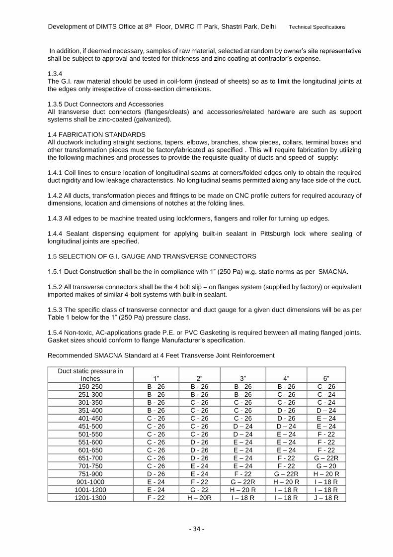
Development of DIMTS Office at 8th Floor, DMRC IT Park, Shastri Park, Delhi Technical Specifications
- 34 -
In addition, if deemed necessary, samples of raw material, selected at random by owner’s site representative shall be subject to approval and tested for thickness and zinc coating at contractor’s expense. 1.3.4 The G.I. raw material should be used in coil-form (instead of sheets) so as to limit the longitudinal joints at the edges only irrespective of cross-section dimensions.
1.3.5 Duct Connectors and Accessories All transverse duct connectors (flanges/cleats) and accessories/related hardware are such as support
systems shall be zinc-coated (galvanized). 1.4 FABRICATION STANDARDS All ductwork including straight sections, tapers, elbows, branches, show pieces, collars, terminal boxes and
other transformation pieces must be factoryfabricated as specified . This will require fabrication by utilizing the following machines and processes to provide the requisite quality of ducts and speed of supply:
1.4.1 Coil lines to ensure location of longitudinal seams at corners/folded edges only to obtain the required
duct rigidity and low leakage characteristics. No longitudinal seams permitted along any face side of the duct. 1.4.2 All ducts, transformation pieces and fittings to be made on CNC profile cutters for required accuracy of
dimensions, location and dimensions of notches at the folding lines. 1.4.3 All edges to be machine treated using lockformers, flangers and roller for turning up edges. 1.4.4 Sealant dispensing equipment for applying built-in sealant in Pittsburgh lock where sealing of
longitudinal joints are specified. 1.5 SELECTION OF G.I. GAUGE AND TRANSVERSE CONNECTORS 1.5.1 Duct Construction shall be the in compliance with 1” (250 Pa) w.g. static norms as per SMACNA. 1.5.2 All transverse connectors shall be the 4 bolt slip – on flanges system (supplied by factory) or equivalent
imported makes of similar 4-bolt systems with built-in sealant. 1.5.3 The specific class of transverse connector and duct gauge for a given duct dimensions will be as per
Table 1 below for the 1” (250 Pa) pressure class. 1.5.4 Non-toxic, AC-applications grade P.E. or PVC Gasketing is required between all mating flanged joints.
Gasket sizes should conform to flange Manufacturer’s specification. Recommended SMACNA Standard at 4 Feet Transverse Joint Reinforcement
Duct static pressure in Inches 1” 2” 3” 4” 6”
150-250 B - 26 B - 26 B - 26 B - 26 C - 26
251-300 B - 26 B - 26 B - 26 C - 26 C - 24
301-350 B - 26 C - 26 C - 26 C - 26 C - 24
351-400 B - 26 C - 26 C - 26 D - 26 D – 24
401-450 C - 26 C - 26 C - 26 D - 26 E – 24
451-500 C - 26 C - 26 D – 24 D – 24 E – 24
501-550 C - 26 C - 26 D – 24 E – 24 F - 22
551-600 C - 26 D - 26 E – 24 E – 24 F - 22
601-650 C - 26 D - 26 E – 24 E – 24 F - 22
651-700 C - 26 D - 26 E – 24 F - 22 G – 22R
701-750 C - 26 E - 24 E – 24 F - 22 G – 20
751-900 D - 26 E - 24 F - 22 G – 22R H – 20 R
901-1000 E - 24 F - 22 G – 22R H – 20 R I – 18 R
1001-1200 E - 24 G - 22 H – 20 R I – 18 R I – 18 R
1201-1300 F - 22 H – 20R I – 18 R I – 18 R J – 18 R

Development of DIMTS Office at 8th Floor, DMRC IT Park, Shastri Park, Delhi Technical Specifications
- 35 -
1301-1500 F - 22 H – 20R I – 18 R I – 18 R -
1501-1800 H – 22R I – 18 R J – 18 R - -
1801-2100 I – 20 R J – 18 R - - -
2101-2400 I – 18 R J - 18 R - - -
2401-2700 I – 18 R - - - -
Note:
� SMACNA – Sheet Metal & Air Conditioning Contractor National Association Inc. “ HVAC Duct construction standard Metal & Flexible” – 2005 USA.
� In 1” static pressure i.e. comfort cooling application optional “ C&S and C&SS cleats joints can be used Upto 450mm duct size use C&S Cleats 451 mm to 750mm duct size use “ C&SS cleats. Over 750mm duct size use TDC Flanges with respective gauges as mentioned above. � Alphabets B, C, D, E, F, G, H, I and J per SMACNA 2005, transverse joint reinforcement table 1-12m (T-
25b flanged). � R means reinforcement with Zeebar Stiffener.
1.6 DUCT CONSTRUCTION 1.6.1 The fabricated duct dimensions should be as per approved drawings and all connecting sections are dimensionally matched to avoid any gaps. 1.6.2 Dimensional Tolerances: All fabricated dimensions will be within +/- 1.0mm of specified dimension. To obtain required perpendicularity, permissible diagonal tolerances shall be +/- 1.0 mm per metre. 1.6.3 Each and every duct pieces should be identified by color coded sticker which shows specific part numbers, job name, drawing number, duct sizes and gauge 1.6.4 Ducts shall be straight and smooth on the inside. Longitudinal seams shall be airtight and at corners only, which shall be either Pittsburgh or Snap Button Punch as per SMACNA practice, to ensure air tightness 1.6.5 Changes in dimensions and shape of ducts shall be gradual (between 1:4 and 1:7). Turning vanes or air splitters shall be installed in all bends and duct collars designed to permit the air to make the turn without appreciable turbulence 1.6.6 Plenums shall be shop/factory fabricated panel type and assembled at site. 1.6.7 The deflection of transverse joints should be within specified limit for rectangular duct deflection as given in SMACNA. Page no. 7.6 1.6.8 Reinforcement of ducts shall be achieved by either cross breaking or straight beading depending on length of ducts As per SMACNA page no. 1.74, fig. 1-8 “Duct Sizes 19” (483 mm) wide and larger which have more than 10 sq.ft. of unbraced panel shall be beaded or cross broken unless ducts will have insulation covering or accoustical liner. This requirement is applicable to 20 g (1.00 mm) or less and 3” W.G. (750 Pa) pressure or less. Ducts for 4” W.G. (1000 Pa) or more do not require beads or cross-breaks.
Table 3 Support for Horizontal duct-Rectangular
Sr. No.
Maximum Duct Size (mm) Hanger Rod
Diameter Interval(mm)
SLOTTED ANGLE IRON SUPPORTS
1. Up to - 700 10 mm 2400
2. 701 - 1200 10 mm 2400
3. 1201 - 2000 10 mm 2400
4. Above 2000 12 mm 2400
1.7 SUPPORT SYSTEM

Development of DIMTS Office at 8th Floor, DMRC IT Park, Shastri Park, Delhi Technical Specifications
- 36 -
A completely galvanized system consisting of fully threaded rods, slotted angles, nuts, washers and anchor bolts as supplied by manufacturer generally conforming to SMACNA standards should be used. 1.7.1 To provide the required thermal brake effect, Neoprene or equivalent material of suitable thickness shall be used between duct supports and duct profiles in all supply air ducts not enclosed by return air plenums. 1.8 INSTALLATION 1.8.1 Tools and tackles for site work The duct installation shall conform to SMACNA norms. For duct assembly and installation the use of suitable tools and tackles should be used to give the required duct quality and speed of installation including (but not restricted to) a) Electric Pittsburgh Seamer – used for closing Pittsburgh joints b) Electric Slitting shear – to make cut-outs c) Drilling machine with drill bits – for drilling holes in sheet metal work d) Hammer drill machine with drill bits – for drilling holes in building structures for anchors e) Hoisting system – for lifting the duct assembly upto mounting heights 1.8.2 Installation Practice All ducts shall be installed as per tender drawings and in strict accordance with approved shop drawings to be prepared by the Contractor. 1.8.3 The Contractor shall provide and neatly erect all sheet metal work as may be required to carry out the intent of these specifications and drawings. The work shall meet with the approval of Owner’s site representative in all its parts and details. 1.8.4 All necessary allowances and provisions shall be made by the Contractor for beams, pipes, or other obstructions in the building whether or not the same are shown on the drawings. Where there is interference/fouling with other beams, structural work, plumbing and conduits, the ducts shall be suitably modified as per actual site conditions. 1.8.5 Ducting over false ceilings shall be supported from the slab above, or from beams. In no case shall any duct be supported from false ceilings hangers or be permitted to rest on false ceiling. All metal work in dead or furred down spaces shall be erected in time to occasion no delay to other contractor’s work in the building. 1.8.6 Where ducts pass through brick or masonry openings, it shall be provided with 25mm thick appropriate insulation around the duct and totally covered with fire barrier mortar for complete sealing. 1.8.7 All ducts shall be totally free from vibration under all conditions of operation. Whenever ductwork is connected to fans, air handling units or blower coil units that may cause vibration in the ducts, ducts shall be provided with a flexible connection, located at the unit discharge. 1.9 DOCUMENTATION & MEASUREMENT FOR DUCTING All ducts fabricated and installed should be accompanied and supported by following documentation: 1. For each drawing, all supply of ductwork must be accompanied by computer generated detailed bill of materials indicating all relevant duct sizes, dimensions and quantities. In addition, summary sheets are also to be provided showing duct area by gauge and duct size range as applicable. 2. Measurement sheet covering each fabricated duct piece showing dimensions and external surface area along with summary of external surface area of duct gauge-wise. 3. All duct pieces to have a part number, which should correspond to the serial number, assigned to it in the measurement sheet. The above system will ensure speedy and proper site measurement, verification and approvals. 1.10 TESTING

Development of DIMTS Office at 8th Floor, DMRC IT Park, Shastri Park, Delhi Technical Specifications
- 37 -
After duct installation, a part of duct section (approximately 5 % of total ductwork) may be selected at random and tested for leakage. The procedure for leak testing should be followed as per SMACNA- “HVAC Air Duct Leakage Test Manual” (First Edition) 1.11 Dampers a. All dampers shall be with louver dampers of robust construction and tightly fitted. The design, method of handling and control shall be suitable for the location and service required. b. Dampers shall be provided with suitable links, levers and quadrants as required for their proper operation; control or setting devices shall be made robust, easily operable and accessible through suitable access doors in the ducts. Every dampers shall have an indicating device clearly showing the damper position at all times. c. Dampers shall be placed in ducts and at every branch of supply air duct connections, whether or not indicated on the drawings for the proper volume control and balancing of the system. d. The construction of MS dampers shall conform to the following specifications : Louver dampers ( with grills / slot diffusers / diffuser plenums ) Frame : 20 Gauge MS sheet Blades : 26 Gauge MS sandwiched aerofoil construction . Box type dampers ( in ducts / duct branches ) Frame : 20 Gauge MS sheet Blades : 22 Gauge MS sheet . 1.12 Motorised Combined Smoke And Fire Dampers – Spring Return Type a. All supply and return air ducts at AHU room crossings and at all floor crossings shall be provided with approved make fire and smoke dampers of atleast 90 minutes fire rating. b. Fire damper blades and outer frame shall be formed of 1.6 MM galvanised sheet steel. The damper blade shall be pivoted on both ends using chrome plated spindles in self lubricated bronze bushes. Stop seals will be provided on top and bottom of the damper housing made of 16 G galvanised sheet steel. For preventing smoke leakage side seals will be provided. In normal position damper blade shall be held in open position with the help of a 24 V operated electric actuators thereby providing maximum air passage without creating any noise ot chatter. c. The damper shall be actuated through electric actuator. The actuator shall be energised with the help of signal from smoke detector installed in AHU room / R.A. duct/Damper. Smoke detector shall also be provided by A/c Contractor. The fire damper shall also close due to temp rise in SA. Ducts thru the electric temp. sensor factory set at 165 Deg. F. micro switches with bakelite base will be provided to stop fan motor and give open and close signal at remote panel in case of motorised actuator. d. Each dampers in case of motorised smoke-cum-damper shall have its own panel which will incorporate necessary circuit required to step down voltage available from UPS or emergency power supply to show status of the damper (open or close) to allow remote testing of damper and indication in event of damper closure due to signal from smoke sensor /temp. sensor and reset button. Additional terminal will be provided to have signal (sound beep or visual) in central control room in case BMS is provided. e. Damper actuator shall be spring return Schneider/ Siemens make so as to close the damper in the event of power failure automatically and open the same in case of power being restored. f. The fire dampers shall be mounted in fire rated wall with s duct sleeve 600 MM long. The sleeve shall be factory fitted on fire damper. The joints at sleeve end shall be slip on type. Minimum thickness of GI sheets shall be 18 G.

Development of DIMTS Office at 8th Floor, DMRC IT Park, Shastri Park, Delhi Technical Specifications
- 38 -
1.13 Supply/ Return Air Diffusers a. Diffusers shall be of approved make and of aluminium construction, round in shape with flush fixed pattern or adjustable flow pattern. Diffusers for different spaces shall be selected in consultation with the Consultant. All supply air diffusers shall be equipped with removable key operated volume control dampers. Anti - smudge ring may be required in specific applications. All extruded aluminium diffusers shall be provided with removable central core and concealed key for operating the volume control damper. The main extruded section shall be minimum 15 mm wide . b. Linear diffusers shall be extruded aluminium construction one or two way blow type. The supply air diffusers shall be provided with volume control dampers to be fitted within the supply air collar. c. Slot diffusers shall be extruded aluminium construction multi slot type complete with Hit and Miss volume control damper. 1.14 Supply/ return air grills Grills shall be of extruded aluminium construction having concealed screws for fixing. These shall be duly powder coated in the shade approved by the architects. The grills shall have horizontal bars at 15/30 deg. inclination and flanges on top and bottom. The grills at the end shall have flange on the side as well as per the site requirement. The size of main extruded section for flanges shall be minimum 15 x 15 mm and the louvers shall be 15 mm deep having thickness of 5 mm in the front and 2.8 mm at the rear . The 150mm / 100 mm grills shall have 10 / 6 louvers respectively . 1.15 Testing and Balancing After completion of the installation of the complete air distribution system, all ducts shall be tested for air leaks. Before painting the interiors, air distribution system shall be allowed to run continuously for 12 hours for driving away any dust or foreign material lodged within ducts during installation. The entire air distribution system shall be balanced using approved anemometer. Air quantities at the fan discharge and at various outlets shall be identical to or less than 5 percent in excess of those specified and quoted. Leakage in each air distribution system shall be tested by smoke test using smoke ball machine . Branch duct adjustments shall be made permanently marked after air balance is complete so that these can be restored to their correct position if disturbed at any time. Complete air balance report shall be submitted to the consultant for scrutiny and approval, and six copies of the approved report shall be provided with completion documents. 1.16 SPIRAL DUCTING The spiral ducting shall be double walled made of 0.91mm thick alumiuum sheet in double skinned construction filled with 25 mm thick polyethylene insulation and will be made with spiral seams complete with duct fittings , standing seams , elbows , reducers , endcaps and offsets . The ducts shall be joined together by slip joint coupling and hung by clamps as per site requirement . 1.17 Testing and Balancing After completion of the installation of the complete air distribution system, all ducts shall be tested for air leaks. Before painting the interiors, air distribution system shall be allowed to run continuously for 12 hours for driving away any dust or foreign material lodged within ducts during installation. The entire air distribution system shall be balanced using approved anemometer. Air quantities at the fan discharge and at various outlets shall be identical to or less than 5 percent in excess of those specified and quoted. Leakage in each air distribution system shall be tested by smoke test using smoke ball machine . Branch duct adjustments shall be made permanently marked after air balance is complete so that these can be restored to their correct position if disturbed at any time. Complete air balance report shall be submitted to the consultant for scrutiny and approval, and six copies of the approved report shall be provided with completion documents. 2. INSULATION 2.1 Scope The scope of this section comprises the supply and application of insulation conforming to these Specifications.
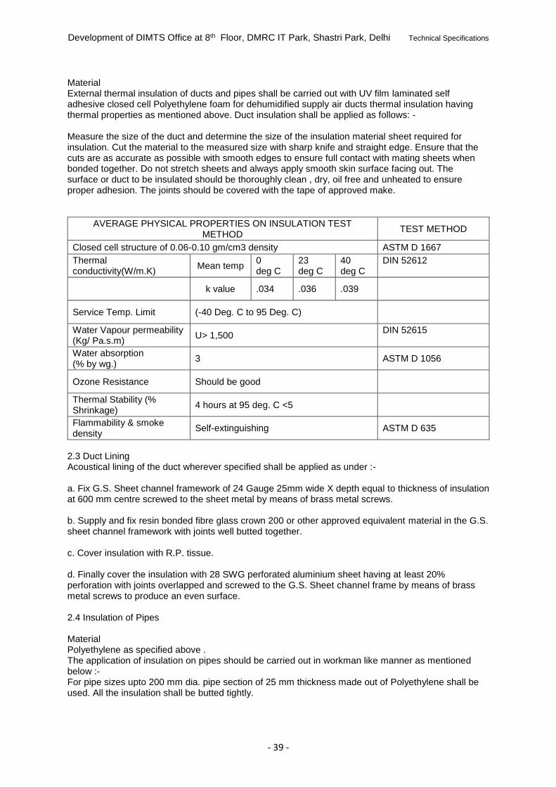
Development of DIMTS Office at 8th Floor, DMRC IT Park, Shastri Park, Delhi Technical Specifications
- 39 -
Material External thermal insulation of ducts and pipes shall be carried out with UV film laminated self adhesive closed cell Polyethylene foam for dehumidified supply air ducts thermal insulation having thermal properties as mentioned above. Duct insulation shall be applied as follows: - Measure the size of the duct and determine the size of the insulation material sheet required for insulation. Cut the material to the measured size with sharp knife and straight edge. Ensure that the cuts are as accurate as possible with smooth edges to ensure full contact with mating sheets when bonded together. Do not stretch sheets and always apply smooth skin surface facing out. The surface or duct to be insulated should be thoroughly clean , dry, oil free and unheated to ensure proper adhesion. The joints should be covered with the tape of approved make.
AVERAGE PHYSICAL PROPERTIES ON INSULATION TEST METHOD
TEST METHOD
Closed cell structure of 0.06-0.10 gm/cm3 density ASTM D 1667
Thermal conductivity(W/m.K)
Mean temp 0 deg C
23 deg C
40 deg C
DIN 52612
k value .034 .036 .039
Service Temp. Limit (-40 Deg. C to 95 Deg. C)
Water Vapour permeability (Kg/ Pa.s.m)
U> 1,500 DIN 52615
Water absorption (% by wg.)
3 ASTM D 1056
Ozone Resistance Should be good
Thermal Stability (% Shrinkage)
4 hours at 95 deg. C <5
Flammability & smoke density
Self-extinguishing ASTM D 635
2.3 Duct Lining Acoustical lining of the duct wherever specified shall be applied as under :- a. Fix G.S. Sheet channel framework of 24 Gauge 25mm wide X depth equal to thickness of insulation at 600 mm centre screwed to the sheet metal by means of brass metal screws. b. Supply and fix resin bonded fibre glass crown 200 or other approved equivalent material in the G.S. sheet channel framework with joints well butted together. c. Cover insulation with R.P. tissue. d. Finally cover the insulation with 28 SWG perforated aluminium sheet having at least 20% perforation with joints overlapped and screwed to the G.S. Sheet channel frame by means of brass metal screws to produce an even surface. 2.4 Insulation of Pipes Material Polyethylene as specified above . The application of insulation on pipes should be carried out in workman like manner as mentioned below :- For pipe sizes upto 200 mm dia. pipe section of 25 mm thickness made out of Polyethylene shall be used. All the insulation shall be butted tightly.

Development of DIMTS Office at 8th Floor, DMRC IT Park, Shastri Park, Delhi Technical Specifications
- 40 -
The insulation shall be applied as follows : a. The pipe to be insulated should be cleaned thoroughly with steel brush for removing dirt, rust and grease (apply chemical solution, if required.) Apply two coats of cold setting adhesive compound on pipes for sticking the insulation pipe sections. Stick Polyethylene pipe sections of specified thickness with longitudinal joints staggered and adjacent sections tightly pressed. Seal all joints with aluminium tape of 50 mm width of approved make. 2.5 Valves and Fittings All valves, fittings, flanges, strainers etc. in the chilled water piping shall be insulated in the same manner as described above. Care should be taken to ensure that no damage would be caused to the insulation when valves or strainers are operated or serviced. 2.6 AHU room acoustic lining Acoustic lining of AHU room shall be applied as under : Fix factory pressed G.S. Sheet channel frame work of 24 guage 50 x 50 mm equal thickness of insulation at 600 mm centre to centre forming a grid work of 600x600, screwed to the walls/ ceiling with brass metal screws. Supply and fix fibre glass 50 mm thick Crown 300 of 32 Kg/ Cum density in the G.S.Sheet channel frame work with joints well butted together. Cover insulation with RP tissue. Finally cover the insulation with 24 SWG perforated aluminium sheet having at least 20% perforation with joints overlapped and screwed to the GS sheet channel frame by means of brass metal screws, to produce an even surface. All joints shall be covered with 20 mm wide x 3 mm thick aluminium strip secured with cup washers and brass metal screws. 3. PIPING : This section deals with supply, installation of pipes, pipe fittings and valves, testing and balancing of all condenser water, chilled water, drain water, hot water piping etc. as detailed in specifications. All piping, fittings and valves etc. shall confirm to relevant Indian standards. Water Piping 3.1 The piping, fittings and valves shall be of approved make and shall confirm to relevant. IS Standards amended to date. 3.2 All pipes in sizes up to 50 mm dia. shall be M.S.ERW tube ( Black steel ) heavy class as per IS:1239-79 Part I for condenser / chilled water lines. 3.3 All pipes in drain water / make up water piping shall be G.I. medium class confirming to IS:1239 Part I and II and IS:4736. 3.4 All pipes in sizes 65 mm to 150 mm diameter shall be M.S.ERW Tube heavy class as per IS:1239:79 Part with latest amendments. For pipes above 200 mm and above it shall confirm to BS 534 / BS 3601 / IS 3589. 3.5 The make of pipes shall be Jindal/ TATA / GST only as per list of approved makes. 3.6 The pipes sizes shall be sized for individual liquid flow and ensure smooth noiseless balanced circulation of fluid. 3.7 All piping and their steel supports shall be thoroughly cleaned and primer coated before installation. 3.8 Pipe Fittings : The pipe fittings for screwed piping shall be malleable iron and piping with welded joints shall be of malleable quality. Also the fittings shall be suitable for same pressure ratings as for the piping system. 3.9 All bends up to sizes 150 mm dia. shall be of heavy duty ready made.

Development of DIMTS Office at 8th Floor, DMRC IT Park, Shastri Park, Delhi Technical Specifications
- 41 -
3.10 All bends in sizes 200 mm and above shall be fabricated from the same dia. and thickness of pipe in at least four sections and having a centre in radius of at least 1.5 times diameter of pipes. Fittings such as tees, reducers etc. shall be from the same pipe and at least of length twice the diameter of the pipe. 3.11 The dead are to be formed with flanged joints and 6 mm thick blank between flange pair for 150 mm and over in case here a future extension is to be made. Otherwise blank end disc 6 mm thickness are to be welded with additional stiffness from 50 mm X 50 mm MS heavy angles. (For sizes above 350 mm)All ends larger than 400 mm dia. shall have dished ends and tested. 3.12 Butterfly valves Butterfly valves made of cast iron body conforming to API 598 shall be as per the following specifications. Body : CI - IS 210 GR FG260 Disc : SGI IS1865 GR 450/10 Body liner : EPDM Disc Liner : Integral Stem : SS 410 The valves upto 200 mm dia shall be hand operated and sizes 250 mm dia and above shall be gear operated. The test pressures shall conform to the following ratings : Shell side : 220 psi hydrostatic Seat : 160 psi hydrostatic The valve rating shall be as per PN 10 class unless otherwise specified. 3.13 Non Return Valve This shall be dual plate type conforming to API 594/ 598. It shall conform to the following specifications: Body : CI IS 210 GR FG260 Plate : ASTM A217 GR CA15 Body seat : Buna N Plate seat : Integral Hinge/ stop pin : SS 410 Spring : SS 316 Bearing : SS 316 The valves shall be tested as per the following ratings: Shell : 350 psi hydrostatic Seat : 200 psi hydrostatic The valve operation should be silent and prevent water hammering 3.14 Y - Strainer or Pot Strainer The pot strainer shall have cast iron/ M.S. body tested at 21 Kg. / Sq.cm. of pressure. The screen shall be made out of 5 mm perforated stainless steel sheet. It should be easily removable when required to be cleaned. Isolating butterfly valves at either end of pot strainer with bypass arrangement with butterfly valve shall be provided. 3.15 Balancing Valves These valves shall conform to the following specifications: Body : Gun metal – IS 318 GR LTB 2(upto 65 mm dia) Cast Iron - GR 260(above 80 mm dia) Seat : SS – ASTM A296 GR CA15 Seal : EPDM Spindle : Non rising type SS – ASTM A267 – 1967 GR 410 Hand wheel : CI 220 Body/ bonnet bolts : A 307 GR B The valves shall be tested at the following pressures: Shell : 400 psi

Development of DIMTS Office at 8th Floor, DMRC IT Park, Shastri Park, Delhi Technical Specifications
- 42 -
Seat : 250 psi These valves shall have built in pressure drop measuring facility 3.16 Portable Mercury Manometer The manometer shall be mercury in glass type. The manometer should be built in stainless steel easy to care metal box. Each manometer shall be complete with 2.5 meter long, 6 mm high pressure nylon reinforced hose on each limb complete with all accessories. It should be designed for differential pressure measurement in the range of 0-60 cm. of mercury with least count of 1mm of mercury. 3.17 Support for Pipes All pipes supports shall be of steel and have anti-corrosive paint before installation. In plant room pipe shall not be supported from ceiling and have steel/ pipe supports of adequate strength, firmly fixed to floor only. 3.18 The sizes and layout given in the drawing / bill of quantities are only for guidance only. The AC contractor shall prepare and submit detailed drawings after the award of contract to consultant for his approval. No work at site shall be started before final approval of drawings is given. The drawings shall indicate sizes of pipes, quantity of water flow in each length of pipe and pressure drops. All details of fittings, location of all valves, air vents etc. shall be clearly indicated on the drawings. All specific openings at site for laying of pipes shall be kept in view while designing and laying of pipes. 3.19 Installation of Condenser / Chilled / Drain / Make up Water Piping a) All pipes shall be securely supported from the floor or suspended from the ceiling by MS rod hangers. The pipe shall be placed on wooden blocks kept on MS channel/angle iron supports clamped with the help of U shaped MS rods bolted to the channel/ angle iron supports . The Air - conditioning contractor shall design all brackets saddles, anchors, clamps, stands & hangers etc. and shall be responsible for structural adequacy. b) All pipe supports shall be of steel, coated with two coats of anti - corrosive paint and finally finished with black enamel paint. c) The pipe spacing shall be as follows : Dia of Pipe Spacing between supports All sizes 2.5 mt The pipe supports shall be firmly fixed on the wall, supported from the floor or hung from ceiling. d) The vertical risers shall run parallel to walls and should be straight /parallel to wall duly checked with plumb line. e) The pipes with / without insulation while passing through the wall /slab shall be provided with sleeve of 50 mm higher size than the pipe with / without insulation. f) Wherever insulated pipes are running, it should be supported in such a way that no extra pressure is put on the insulated pipe. 3.20 System Balancing The system shall be balanced to achieve the design water flow rates follows: a) Advance make balancing valves and manometer shall be used for balancing and adjusting the system for the required flow rates. b) The three - way diverting valves / automatic control valves shall be balanced and adjusted for design flow of water. c) AC Contractor shall submit balancing report to AC consultant for final approval. 3.21 Testing of Pipe System a) All tools, tackles, services labour shall be arranged by AC Contractor.

Development of DIMTS Office at 8th Floor, DMRC IT Park, Shastri Park, Delhi Technical Specifications
- 43 -
b) The chilled water pipe line shall be hydraulically tested at 150 psig for 24 hours duration. All leaks occurring during testing shall be rectified to the satisfaction of AC consultant. After repairs of leak it shall be tested again at the same pressure c) In case piping is tested in parts, these sections shall be securely sealed and capped. d) The AC contractor shall make sure that the fluid shall flow in pipes and AHU coils without noise. e) In case design water circulation through heat exchangers is not achieved due to any reason , it shall be rectified by the AC contractor. 3.22 Air Vents Air valve for purging of air blocked in piping system shall be provided at the highest summit. Gate valves of specified sizes shall be provided at the designated points The sizes of air valves shall be as specified below : Upto 100 mm 19 mm dia air valves Above 100 mm to 300 mm 25 mm dia air valves 3.23 Pressure Gauges Feibig or equivalent make bourden type pressure gauges of 100 mm dia. of suitable range shall be provided at the following locations : a) Chiller / Cooling coils - Inlets and Outlets. b) Suction and discharge of all pumps. c) Other designated points d) All pressure gauges shall be complete with gate valves of 3/8” dia and conform to IS:3624 3.24 Thermometer Dial type thermometer of 100 mm dia of suitable range shall be provided at the following locations. a) Chiller / Cooling coil - Inlets and Outlets. 4. FAN COIL UNITS SCOPE The scope of this section comprises the supply, erection, testing and commissioning of fan coil units conforming of these specifications and in accordance with the requirements of the Drawings and Schedule of Quantities. TYPE The fan coil units shall be cassette type for ceiling suspension.. All units shall be complete with chilled water coil. One or more centrifugal fans and motor, cleanable fabric filters, insulated condensate drain pan, ball valve set, 2 way motorized valve, drain pump with drain pump failure alarm and wall mounted or remote soft touch control with display panel & remote control.. CAPACITY The air moving and coil capacities shall be as shown on Drawings and indicated in Schedule of quantities. DRAIN PAN The drain pan shall be part of the main cassette unit fitted with drain pump and necessary connections for connecting the same to the drain pipes. COOLING COIL All cooling coils shall be standard three or four row staggered seamless copper tube with aluminium sine wave fins. Tubes shall be minimum 9 mm OD & 0.35 mm copper thick. All bends and joints shall be enclosed within insulated end sections of the base unit for protection against sweating. Each coil shall be provided with an air vent. All coils shall be factory tested at 21 KG per sq.cm (300 psi) air pressure while submerged in water. Fin spacing shall be 4 to 5 fins per cm. Tubes shall be mechanically / hydraulically expanded for minimum thermal contact resistance with fins. Air vent shall be provided in header at a level higher than coils. FANS Fans shall be centrifugal forward curve, direct driven. This shall consist of (2) two light weight aluminium impeller of forward curved type both statically & dynamically balanced along with properly designed G.I sheet casing.

Development of DIMTS Office at 8th Floor, DMRC IT Park, Shastri Park, Delhi Technical Specifications
- 44 -
MOTOR Motor shall be 220 + 10% volts, 50 cycles, single phase, six pole, shaded pole type, speed not exceeding 1000 RPM at maximum airflow. Motors shall have three speed windings and shall be factory wired to a terminal block mounted within the fan section. Motors shall be have extended shaft on both sides. INSTALLATION Ceiling suspended horizontal units and units mounted within the ceiling space shall be hung through Dunlop / Emerald make rubber in shear vibration isolator suspenders. ACCESSORIES All fan coil units shall be equipped with copper piping connections and manual air vent at the cooling coil. In addition, the following accessories may be required at fan coil unit; their detailed specifications are given in individual sections and quantities separately in Schedule of Quantities. 1. The contractor or supplier shall install wall mounted thermostat for individual unit. 2. The fan coil unit shall be complete with ball valve set, 2 way motorized valve and wall mounted soft touch control with display panel & remote control. 3. Drain pump. PERFORMANCE DATA Fan coil units shall be selected for the lowest operating noise level of the equipment. Fan performance rating and power consumption data, with operating points clearly indicated shall be submitted by the Contractor with Technical Bid and verified at the time of testing and commissioning of the installation. PERFORMANCE DATA Cooling capacity of various fan coil unit models shall be computer from the measurements of airflow and dry and wet bulb temperature of air entering and leaving the coil. Flow measurements shall be by anemometer and temperature measurements by accurately calibrated mercury in glass thermometers. Computed ratings shall confirm to the specified capacities and quoted ratings. Power consumption shall be computed from measurements of incoming voltage and input current. MODE OF MEASUREMENT A. DUCTS Unless otherwise specified, measurements for ducting for the project shall be on the basis of centre-line measurements described herewith : a. Duct work shall be measured on the basis of external surface area of ducts. Duct measurements shall be taken before application of the insulation. The external surface area shall be calculated by measuring the perimeter comprising overall width and depth, including the corner joints, in the centre of each duct section, multiplying with the overall length from flange face to flange face of each duct section and adding up areas of all duct sections. Plenums shall also be measured in similar manner. For tapered rectangular ducts, the average width and depth shall be considered for perimeter, whereas for tapered circular ducts, the diameter of the section midway between large and small diameter shall be adopted, the length of tapered duct section shall be the centre line distance between the flanges of the duct section. For special pieces like bends, tees, reducers, branches and collars, mode of measurement shall be identical to that described above using the length along the centre line. The quoted unit rate for external surface of ducts shall include wastage allowances, flanges and gaskets for nuts, joints, bolts, hangers and angles with double nuts for supports, rubber strip 3 mm thick between ducts, vibration isolator suspension where specified or required, inspection chamber/ access panel, splitter damper. These accessories shall NOT be separately measured nor paid for. b. Special items for air distribution shall be measured by the cross-section area perpendicular to air flow, as identified herewith : i. Grilles and registers – width multiplied by height, excluding flanges.
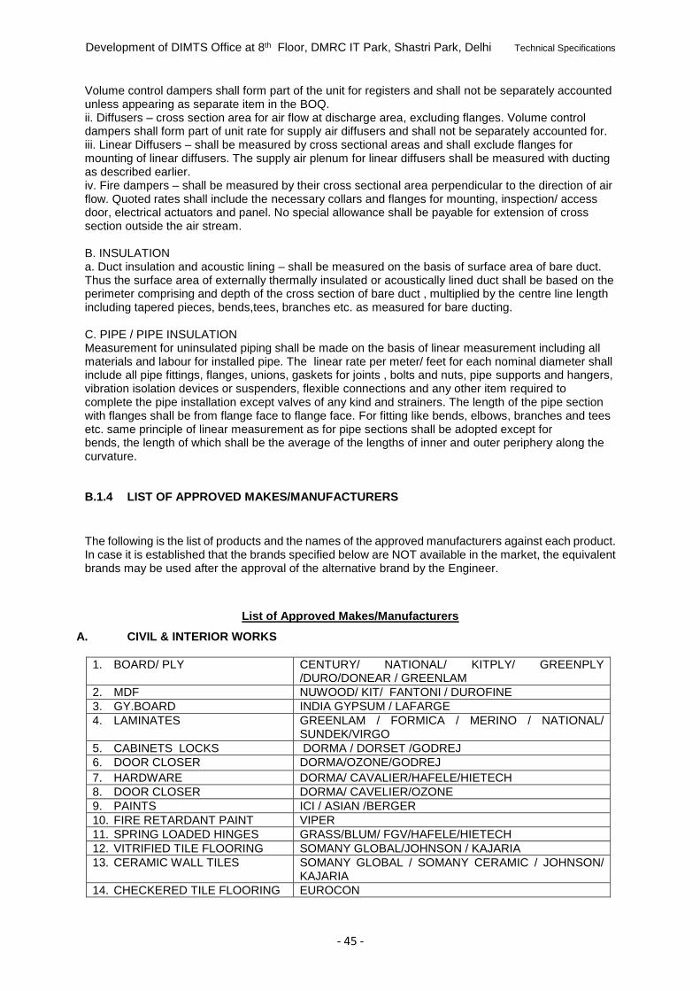
Development of DIMTS Office at 8th Floor, DMRC IT Park, Shastri Park, Delhi Technical Specifications
- 45 -
Volume control dampers shall form part of the unit for registers and shall not be separately accounted unless appearing as separate item in the BOQ. ii. Diffusers – cross section area for air flow at discharge area, excluding flanges. Volume control dampers shall form part of unit rate for supply air diffusers and shall not be separately accounted for. iii. Linear Diffusers – shall be measured by cross sectional areas and shall exclude flanges for mounting of linear diffusers. The supply air plenum for linear diffusers shall be measured with ducting as described earlier. iv. Fire dampers – shall be measured by their cross sectional area perpendicular to the direction of air flow. Quoted rates shall include the necessary collars and flanges for mounting, inspection/ access door, electrical actuators and panel. No special allowance shall be payable for extension of cross section outside the air stream. B. INSULATION a. Duct insulation and acoustic lining – shall be measured on the basis of surface area of bare duct. Thus the surface area of externally thermally insulated or acoustically lined duct shall be based on the perimeter comprising and depth of the cross section of bare duct , multiplied by the centre line length including tapered pieces, bends,tees, branches etc. as measured for bare ducting. C. PIPE / PIPE INSULATION Measurement for uninsulated piping shall be made on the basis of linear measurement including all materials and labour for installed pipe. The linear rate per meter/ feet for each nominal diameter shall include all pipe fittings, flanges, unions, gaskets for joints , bolts and nuts, pipe supports and hangers, vibration isolation devices or suspenders, flexible connections and any other item required to complete the pipe installation except valves of any kind and strainers. The length of the pipe section with flanges shall be from flange face to flange face. For fitting like bends, elbows, branches and tees etc. same principle of linear measurement as for pipe sections shall be adopted except for bends, the length of which shall be the average of the lengths of inner and outer periphery along the curvature. B.1.4 LIST OF APPROVED MAKES/MANUFACTURERS
The following is the list of products and the names of the approved manufacturers against each product. In case it is established that the brands specified below are NOT available in the market, the equivalent brands may be used after the approval of the alternative brand by the Engineer.
List of Approved Makes/Manufacturers
A. CIVIL & INTERIOR WORKS
1. BOARD/ PLY CENTURY/ NATIONAL/ KITPLY/ GREENPLY /DURO/DONEAR / GREENLAM
2. MDF NUWOOD/ KIT/ FANTONI / DUROFINE
3. GY.BOARD INDIA GYPSUM / LAFARGE
4. LAMINATES GREENLAM / FORMICA / MERINO / NATIONAL/ SUNDEK/VIRGO
5. CABINETS LOCKS DORMA / DORSET /GODREJ
6. DOOR CLOSER DORMA/OZONE/GODREJ
7. HARDWARE DORMA/ CAVALIER/HAFELE/HIETECH
8. DOOR CLOSER DORMA/ CAVELIER/OZONE
9. PAINTS ICI / ASIAN /BERGER
10. FIRE RETARDANT PAINT VIPER
11. SPRING LOADED HINGES GRASS/BLUM/ FGV/HAFELE/HIETECH
12. VITRIFIED TILE FLOORING SOMANY GLOBAL/JOHNSON / KAJARIA
13. CERAMIC WALL TILES SOMANY GLOBAL / SOMANY CERAMIC / JOHNSON/ KAJARIA
14. CHECKERED TILE FLOORING EUROCON
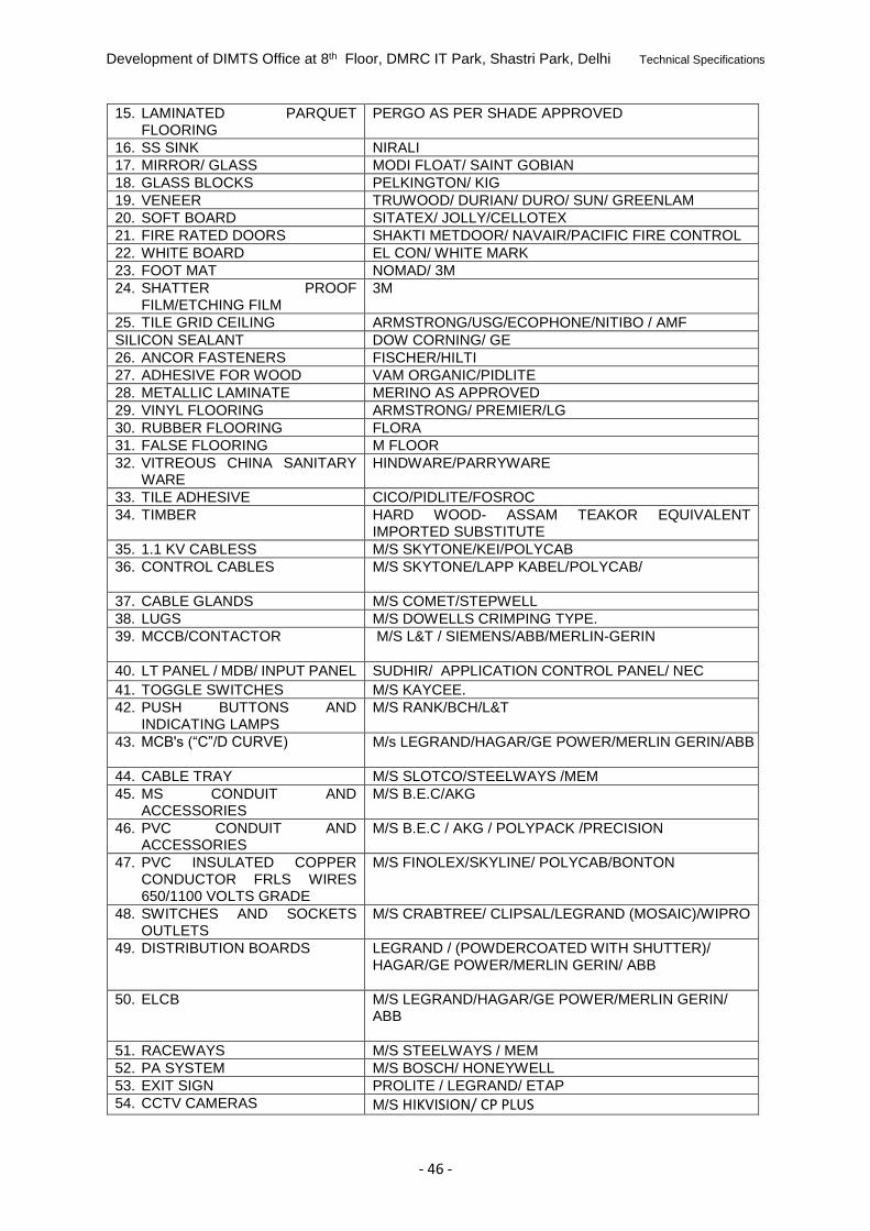
Development of DIMTS Office at 8th Floor, DMRC IT Park, Shastri Park, Delhi Technical Specifications
- 46 -
15. LAMINATED PARQUET FLOORING
PERGO AS PER SHADE APPROVED
16. SS SINK NIRALI
17. MIRROR/ GLASS MODI FLOAT/ SAINT GOBIAN
18. GLASS BLOCKS PELKINGTON/ KIG
19. VENEER TRUWOOD/ DURIAN/ DURO/ SUN/ GREENLAM
20. SOFT BOARD SITATEX/ JOLLY/CELLOTEX
21. FIRE RATED DOORS SHAKTI METDOOR/ NAVAIR/PACIFIC FIRE CONTROL
22. WHITE BOARD EL CON/ WHITE MARK
23. FOOT MAT NOMAD/ 3M
24. SHATTER PROOF FILM/ETCHING FILM
3M
25. TILE GRID CEILING ARMSTRONG/USG/ECOPHONE/NITIBO / AMF
SILICON SEALANT DOW CORNING/ GE
26. ANCOR FASTENERS FISCHER/HILTI
27. ADHESIVE FOR WOOD VAM ORGANIC/PIDLITE
28. METALLIC LAMINATE MERINO AS APPROVED
29. VINYL FLOORING ARMSTRONG/ PREMIER/LG
30. RUBBER FLOORING FLORA
31. FALSE FLOORING M FLOOR
32. VITREOUS CHINA SANITARY WARE
HINDWARE/PARRYWARE
33. TILE ADHESIVE CICO/PIDLITE/FOSROC
34. TIMBER HARD WOOD- ASSAM TEAKOR EQUIVALENT IMPORTED SUBSTITUTE
35. 1.1 KV CABLESS M/S SKYTONE/KEI/POLYCAB
36. CONTROL CABLES M/S SKYTONE/LAPP KABEL/POLYCAB/
37. CABLE GLANDS M/S COMET/STEPWELL
38. LUGS M/S DOWELLS CRIMPING TYPE.
39. MCCB/CONTACTOR M/S L&T / SIEMENS/ABB/MERLIN-GERIN
40. LT PANEL / MDB/ INPUT PANEL SUDHIR/ APPLICATION CONTROL PANEL/ NEC
41. TOGGLE SWITCHES M/S KAYCEE.
42. PUSH BUTTONS AND INDICATING LAMPS
M/S RANK/BCH/L&T
43. MCB's (“C”/D CURVE) M/s LEGRAND/HAGAR/GE POWER/MERLIN GERIN/ABB
44. CABLE TRAY M/S SLOTCO/STEELWAYS /MEM
45. MS CONDUIT AND ACCESSORIES
M/S B.E.C/AKG
46. PVC CONDUIT AND ACCESSORIES
M/S B.E.C / AKG / POLYPACK /PRECISION
47. PVC INSULATED COPPER CONDUCTOR FRLS WIRES 650/1100 VOLTS GRADE
M/S FINOLEX/SKYLINE/ POLYCAB/BONTON
48. SWITCHES AND SOCKETS OUTLETS
M/S CRABTREE/ CLIPSAL/LEGRAND (MOSAIC)/WIPRO
49. DISTRIBUTION BOARDS LEGRAND / (POWDERCOATED WITH SHUTTER)/ HAGAR/GE POWER/MERLIN GERIN/ ABB
50. ELCB M/S LEGRAND/HAGAR/GE POWER/MERLIN GERIN/ ABB
51. RACEWAYS M/S STEELWAYS / MEM
52. PA SYSTEM M/S BOSCH/ HONEYWELL
53. EXIT SIGN PROLITE / LEGRAND/ ETAP
54. CCTV CAMERAS M/S HIKVISION/ CP PLUS
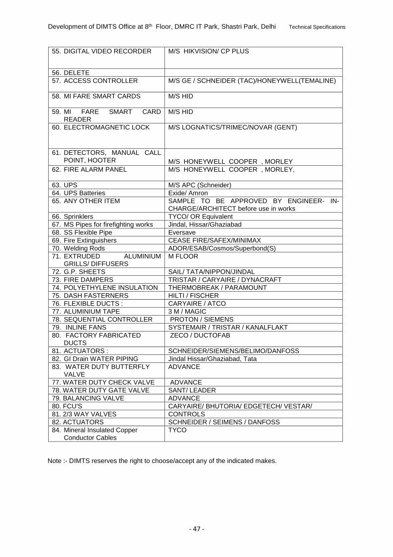
Development of DIMTS Office at 8th Floor, DMRC IT Park, Shastri Park, Delhi Technical Specifications
- 47 -
55. DIGITAL VIDEO RECORDER M/S HIKVISION/ CP PLUS
56. DELETE M/S
57. ACCESS CONTROLLER M/S GE / SCHNEIDER (TAC)/HONEYWELL(TEMALINE)
58. MI FARE SMART CARDS M/S HID
59. MI FARE SMART CARD READER
M/S HID
60. ELECTROMAGNETIC LOCK M/S LOGNATICS/TRIMEC/NOVAR (GENT)
61. DETECTORS, MANUAL CALL POINT, HOOTER
M/S HONEYWELL COOPER , MORLEY
62. FIRE ALARM PANEL M/S HONEYWELL COOPER , MORLEY,
63. UPS M/S APC (Schneider)
64. UPS Batteries Exide/ Amron
65. ANY OTHER ITEM SAMPLE TO BE APPROVED BY ENGINEER- IN-CHARGE/ARCHITECT before use in works
66. Sprinklers TYCO/ OR Equivalent
67. MS Pipes for firefighting works Jindal, Hissar/Ghaziabad
68. SS Flexible Pipe Eversave
69. Fire Extinguishers CEASE FIRE/SAFEX/MINIMAX
70. Welding Rods ADOR/ESAB/Cosmos/Superbond(S)
71. EXTRUDED ALUMINIUM GRILLS/ DIFFUSERS
M FLOOR
72. G.P. SHEETS SAIL/ TATA/NIPPON/JINDAL
73. FIRE DAMPERS TRISTAR / CARYAIRE / DYNACRAFT
74. POLYETHYLENE INSULATION THERMOBREAK / PARAMOUNT
75. DASH FASTERNERS HILTI / FISCHER
76. FLEXIBLE DUCTS : CARYAIRE / ATCO
77. ALUMINIUM TAPE 3 M / MAGIC
78. SEQUENTIAL CONTROLLER PROTON / SIEMENS
79. INLINE FANS SYSTEMAIR / TRISTAR / KANALFLAKT
80. FACTORY FABRICATED DUCTS
ZECO / DUCTOFAB
81. ACTUATORS : SCHNEIDER/SIEMENS/BELIMO/DANFOSS
82. GI Drain WATER PIPING Jindal Hissar/Ghaziabad, Tata
83. WATER DUTY BUTTERFLY VALVE
ADVANCE
77. WATER DUTY CHECK VALVE ADVANCE
78. WATER DUTY GATE VALVE SANT/ LEADER
79. BALANCING VALVE ADVANCE
80. FCU'S CARYAIRE/ BHUTORIA/ EDGETECH/ VESTAR/
81. 2/3 WAY VALVES CONTROLS
82. ACTUATORS SCHNEIDER / SEIMENS / DANFOSS
84. Mineral Insulated Copper Conductor Cables
TYCO
Note :- DIMTS reserves the right to choose/accept any of the indicated makes.

Development of DIMTS Office at 8th Floor, DMRC IT Park, Shastri Park, Delhi Technical Specifications
- 48 -
Annexure-I to Technical Specifications
SCOPE OF WORK & SITE INFORMATION
1. Site Information
1.1.1 Work Site
1.1.2 The project site is located in the NCT of Delhi. The location of the work is within the
premises of Delhi IT Park of DMRC at Shastri Park, Delhi.
1.1.3 The work is to be carried out at the 8th floor of the Delhi IT Park of DMRC at Shastri Park,
Delhi Building.
1.1.4 The contractor shall plan his works keeping in view restrictions of approach and availability
of space and time and keeping in view fit out guidelines issued by DMRC.
1.2 Seismic zone
Delhi falls in seismic zone IV. Earthquake of maximum magnitude VIII on Modified
Mercalli scale has been experienced in the past, in the region.
The above site information is being made available to bidders in good faith and bidders are
advised to obtain relevant information, as may be considered necessary by them, before
quoting the bid. No claim what so ever on account of any discrepancy of the above
information shall be entertained.
2. Scope of Work
2.1.1 The objective of the contract is development of DIMTS Ltd. Office at 8th floor, Delhi IT Park,
DMRC at Shastri Park, Delhi Building.
2.2 Scope of work shall include, but not limited to, the following:
a) Civil & Interior Works,
b) HVAC Works,.
c) Electrical Works,
d) Firefighting Works,
e) FDA System,
f) Access Control System,
g) CCTV System,
h) PA System,
i) IT Networking/Structured Cabling,
j) UPS System,
k) Modular Workstations & Loose Furniture
l) Any other work required for the completion of work
m) Tentative drawings of the work (sitting plan) is being provided with this tender
document. The contractor shall have to develop detailed design and Good for construction
drawings/ sitting drawing for the approval of DIMTS before commencement of work.

Development of DIMTS Office at 8th Floor, DMRC IT Park, Shastri Park, Delhi Technical Specifications
- 49 -