1 plate efficiencies plate efficiencies 1. types of plate efficiency (1) overall efficiency e t...
TRANSCRIPT

1
Plate efficienciesPlate efficiencies1. Types of plate efficiency 1. Types of plate efficiency
(1) Overall efficiency E(1) Overall efficiency ETT
(2)Murphree efficiency E(2)Murphree efficiency E
MVMV, E, EMLML
y*y*nn is in equilibrium is in equilibrium
with xwith xnn..
x*x*nn is in equilibrium is in equilibrium
with ywith ynn..

2
(3) Local efficiency E(3) Local efficiency Eoo
y* is in equilibrium with x.y* is in equilibrium with x.
3
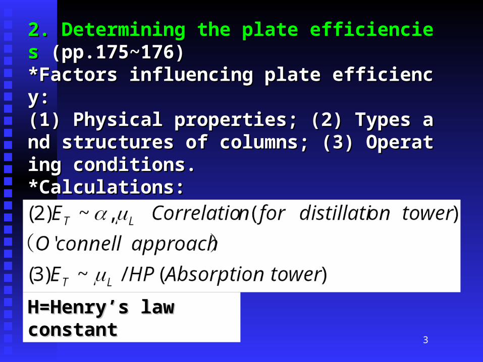
2. Determining the plate efficiencies2. Determining the plate efficiencies (pp.175~176) (pp.175~176) *Factors influencing plate efficiency: *Factors influencing plate efficiency: (1) Physical properties; (2) Types and structures of (1) Physical properties; (2) Types and structures of columns; (3) Operating conditions. columns; (3) Operating conditions. *Calculations: *Calculations:
(1) AIChE approach to local efficiency;(1) AIChE approach to local efficiency;
H=Henry’s law constantH=Henry’s law constant

4
3-1-1 Types of trays3-1-1 Types of trays
•Describe the constructions, operating principles, and Describe the constructions, operating principles, and characteristics of several frequently used trays, for characteristics of several frequently used trays, for examples, sieve-trays; bubble-cap trays; valve-trays; etc. examples, sieve-trays; bubble-cap trays; valve-trays; etc. •[Comparing the turndown ratio; plate efficiencies; [Comparing the turndown ratio; plate efficiencies; pressure drops; fabricating cost; production capacity of pressure drops; fabricating cost; production capacity of these 3 kinds of trays.] these 3 kinds of trays.]
5
3-1-3 Design of Valve tray columns3-1-3 Design of Valve tray columns
•Understanding the meanings of symbols in Understanding the meanings of symbols in Figure 3-10. [p.158]Figure 3-10. [p.158]

6

7
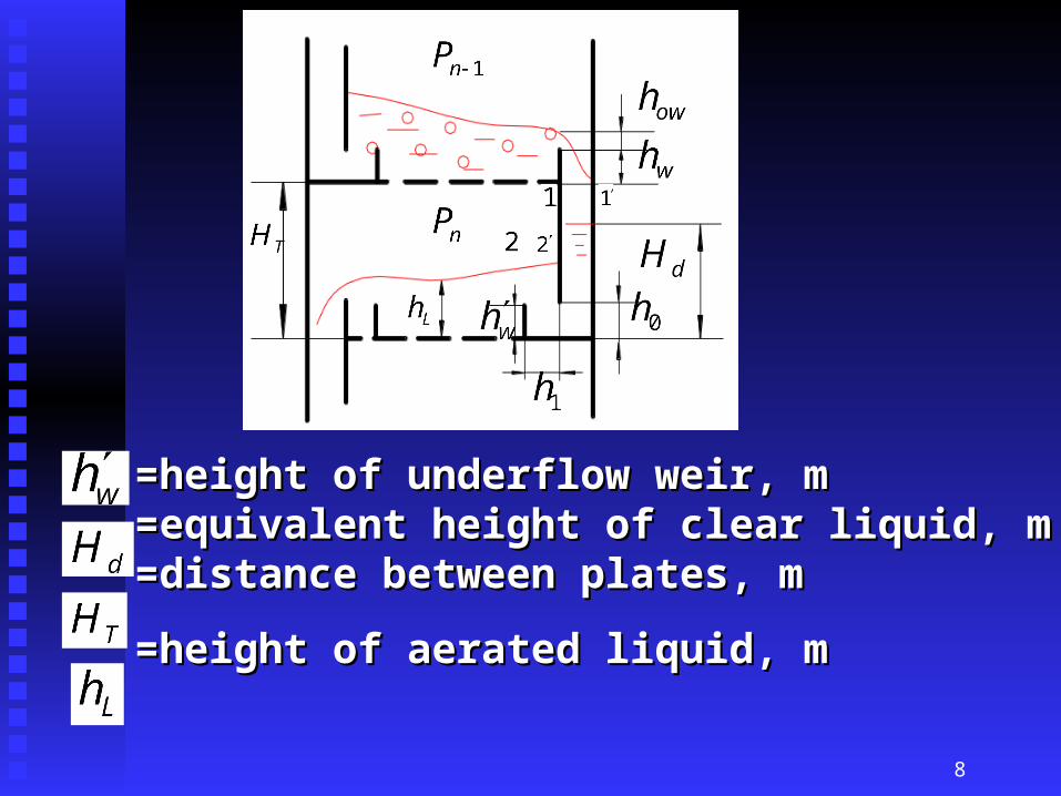
=height of weir, m =height of weir, m =height of clear liquid over weir, m =height of clear liquid over weir, m =spacing between downcomer bottom and tray, m =spacing between downcomer bottom and tray, m
=horizontal distance between downcomer and unde=horizontal distance between downcomer and underflow weir, mrflow weir, m
8
=height of underflow weir, m =height of underflow weir, m =equivalent height of clear liquid, m =equivalent height of clear liquid, m =distance between plates, m =distance between plates, m
=height of aerated liquid, m=height of aerated liquid, m

9
=length of weir, m =length of weir, m =width of straight seg=width of straight segmental weir, m mental weir, m =width of defoaming =width of defoaming area, m area, m =width of installation =width of installation area, m area, m =column diameter, m =column diameter, m =radius of active area, =radius of active area, m m
=half the width of acti=half the width of active area, mve area, m =distance between centers =distance between centers
of openings of valve trays of openings of valve trays of the same row, mof the same row, m

10
•Sectional Design: Sectional Design: Usually the column diameter will not change Usually the column diameter will not change along the direction of column height, in order for along the direction of column height, in order for the convenience of fabrication, installation, and the convenience of fabrication, installation, and maintenance/repairs, except for the great changes maintenance/repairs, except for the great changes of vapor and liquid flow rates. of vapor and liquid flow rates.
In practice, because of great differences of vapor In practice, because of great differences of vapor and liquid flow rates between rectifying section and liquid flow rates between rectifying section and stripping section, the column is separated into and stripping section, the column is separated into two sections when designing.two sections when designing.

11
•[Sectional Design] [Sectional Design]
When designing a column, take the average flow When designing a column, take the average flow rates, average physical properties, and average rates, average physical properties, and average operating conditions of every section; adjust the operating conditions of every section; adjust the capacity performance chart to the optimum capacity performance chart to the optimum turndown ratio; check the cross sections of maximum turndown ratio; check the cross sections of maximum and minimum flow rates to and minimum flow rates to make sure the two limit make sure the two limit operating points fall into the satisfactory operation operating points fall into the satisfactory operation zone.zone.

12
•Design and calculation procedures: Design and calculation procedures: •(1) Calculation of column height; (1) Calculation of column height; (2) Calculation of column diameter; (2) Calculation of column diameter; (3) Design of down-comer/overflow area; (3) Design of down-comer/overflow area; (4) Design of active area; (4) Design of active area; (5) Checking the performance of fluid mechanics; (5) Checking the performance of fluid mechanics;
(6) Adjusting the capacity performance chart. (6) Adjusting the capacity performance chart.

13
•Conditions given for the design:Conditions given for the design:
Vapor and liquid flow rates:Vapor and liquid flow rates:
Physical properties:Physical properties:
Operating parameters:Operating parameters:

14
(1)Liquid density: (1)Liquid density: Average density, such aAverage density, such as rectifying section: s rectifying section: (2) Density of vapor mi(2) Density of vapor mixture: xture:
Average density, such aAverage density, such as rectifying section:s rectifying section:

15
(3)Latent heat of va(3)Latent heat of vaporization of liquid porization of liquid mixture: mixture: (4) Surface tension (4) Surface tension of liquid mixture: of liquid mixture:
(5)Average temper(5)Average temperature and pressure, ature and pressure, such as rectifying ssuch as rectifying section:ection:
16
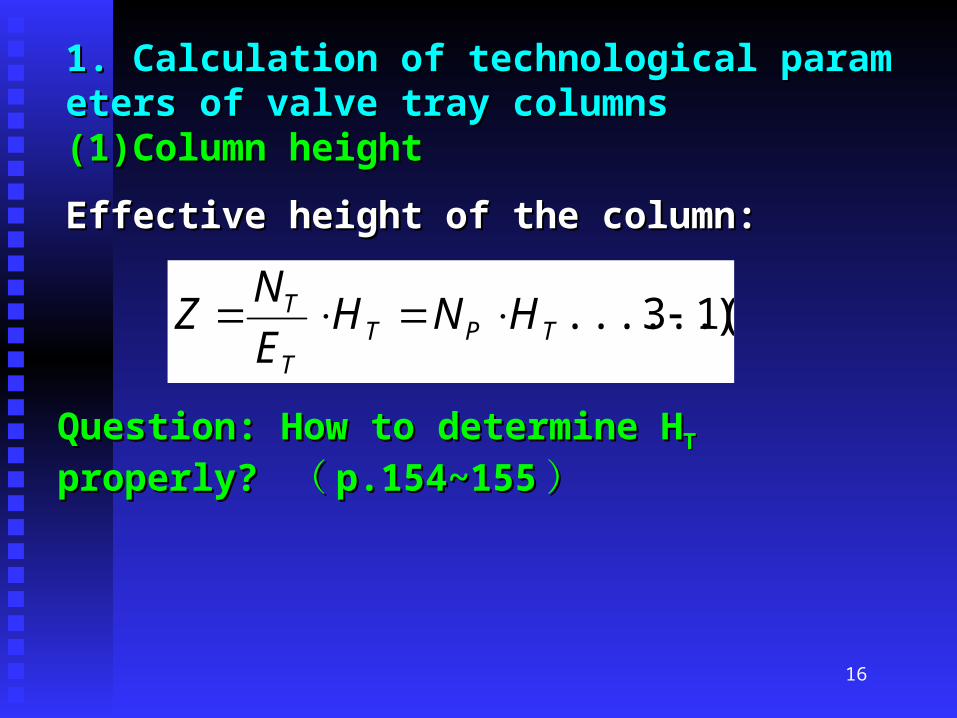
1. Calculation of technological parameters of valve t1. Calculation of technological parameters of valve tray columns ray columns (1)Column height (1)Column height
Effective height of the column:Effective height of the column:
)13......( TPTT
T HNHE
NZ
Question: How to determine HQuestion: How to determine HTT properly? properly?
(( p.154~155p.154~155 ))

17
(2)Column diameter(2)Column diameter
max8.0~6.0
)23......(4
uuu
VD S
)(
uumaxmax is determined by excessive froth entrainment o is determined by excessive froth entrainment o
r flooding.r flooding.

18
According to the settling principle, the maximum According to the settling principle, the maximum permissible vapor velocity is derived as follows:permissible vapor velocity is derived as follows:
C=capacity factorC=capacity factor

19
Firstly, estimate the column diameter D, select HFirstly, estimate the column diameter D, select HTT an an
d hd hLL, get C, get C2020 from Fig.3-8 and from Fig.3-8 and
20
(3)Downcomer (3)Downcomer 1)Weir 1)Weir •Function of weir: Making sure there is certain liFunction of weir: Making sure there is certain liquid layer on the plate, and making sure the liquiquid layer on the plate, and making sure the liquid flow uniformly. d flow uniformly. •Length of weir lLength of weir lww: Decided by liquid flow rate an: Decided by liquid flow rate an
d types of downcomers. d types of downcomers.
•Single downcomer: lSingle downcomer: lww/D=(0.6~0.8); two downco/D=(0.6~0.8); two downco
mers: lmers: lww/D=(0.5~0.6)/D=(0.5~0.6)

21
•Height of weir hHeight of weir hww :: hhww = h = hLL – h – howow
Selecting the liquid layer height on plate hSelecting the liquid layer height on plate hLL, and , and
calculating hcalculating hOWOWhhw w
(Straight segmental weir: h(Straight segmental weir: howow>6mm>6mm ; ;
When hWhen howow<6mm <6mm ,, selecting saw-tooth-like segmselecting saw-tooth-like segm
ental weir.)ental weir.)

22
2)Basic design principle of width W2)Basic design principle of width Wdd and cross secti and cross secti
onal area Aonal area Af f of straight segmental weir: Making surof straight segmental weir: Making sur
e that there is enough residence time for liquid in te that there is enough residence time for liquid in the downcomer to avoid vapor bubble entrainment. he downcomer to avoid vapor bubble entrainment. After getting AAfter getting Aff from l from lww/D, check:/D, check:
?)5~3(, sL
HA
S
Tf
3)Spacing between downcomer bottom and tray: h3)Spacing between downcomer bottom and tray: h0 0
Design principle: lessening local resistance of liquid Design principle: lessening local resistance of liquid flow ; possessing the function of liquid seal, at the saflow ; possessing the function of liquid seal, at the same time avoiding the blockage of downcomer.me time avoiding the blockage of downcomer.

23
4)Underflow weir and liquid accumulator 4)Underflow weir and liquid accumulator 进口堰进口堰及受液盘 及受液盘 •Setting underflow weir for large columns.Setting underflow weir for large columns. [p.158, [p.158,Fig.3-10] Fig.3-10] Functions: 1) liquid seal; 2)Uniform flow of liquid Functions: 1) liquid seal; 2)Uniform flow of liquid on plate. on plate. •For column diameter D>800mm, using liquid accFor column diameter D>800mm, using liquid accumulator.umulator. [p.161, Fig.3-14] [p.161, Fig.3-14]
Functions: Side-stream drawoff; liquid seal; buffeFunctions: Side-stream drawoff; liquid seal; bufferingring 缓冲缓冲 . Liquid accumulator does not apply to t. Liquid accumulator does not apply to the easily polymerizing materials and suspending she easily polymerizing materials and suspending solids.olids.

24
(4)Layout of plate(4)Layout of plate
•Four areas. Four areas.
•Purpose of defoaming area: Avoiding weeping iPurpose of defoaming area: Avoiding weeping in liquid inlet and defoaming.n liquid inlet and defoaming.
installation areainstallation area
Downcomer Downcomer areaarea
Active Active areaarea
Defoaming areaDefoaming area
25
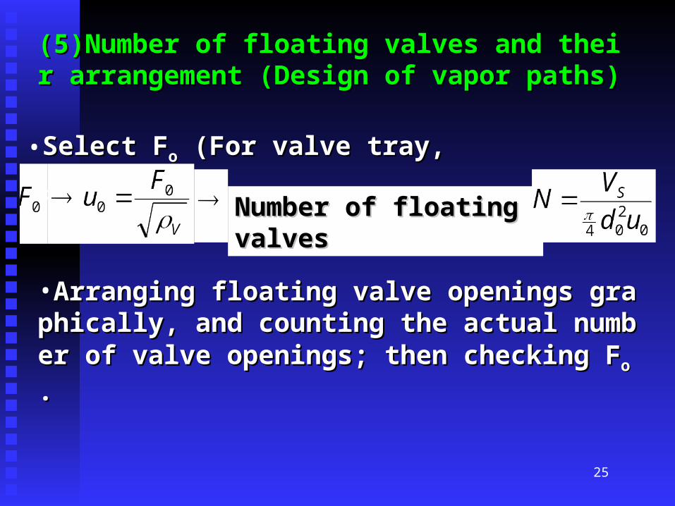
(5)Number of floating valves and their arrangement (5)Number of floating valves and their arrangement (Design of vapor paths)(Design of vapor paths)
•Select FSelect Foo (For valve tray, F (For valve tray, Foo=9~12)=9~12)
Number of floating valvesNumber of floating valves
•Arranging floating valve openings graphically, and cArranging floating valve openings graphically, and counting the actual number of valve openings; then chounting the actual number of valve openings; then checking Fecking Fo o ..

26
2. Performance examination of fluid mechanics (pp.2. Performance examination of fluid mechanics (pp.163~167) 163~167) •Auxiliary equipment: Auxiliary equipment: Condenser and its heat transfer area FCondenser and its heat transfer area Fc c (m(m22) )
Reboiler and its heat transfer area FReboiler and its heat transfer area Fhh (m (m22) )
Flow rate of cooling medium WFlow rate of cooling medium Wcc (kg/h) (kg/h)
Flow rate of heating medium WFlow rate of heating medium Whh (kg/h) (kg/h)

27
•Operation of columns: Operation of columns: (1) Basic requirements:(1) Basic requirements: Vapor and liquid counter-flo Vapor and liquid counter-flow along the column height direction, and cross-flow ow along the column height direction, and cross-flow on plate. Vapor and liquid mixes well on plate and witn plate. Vapor and liquid mixes well on plate and without detrimental operations. hout detrimental operations. (2)Phenomena, judging and regulations: (2)Phenomena, judging and regulations: 1)Temperature of reboiler decreases, and column pre1)Temperature of reboiler decreases, and column pressure decreases too. ssure decreases too. Possible reason: Weeping. Possible reason: Weeping.
Measures for avoiding weeping: Increasing vapor velMeasures for avoiding weeping: Increasing vapor velocity; Setting defoaming area at the inlet of liquid.ocity; Setting defoaming area at the inlet of liquid.
28
2)Temperature on the top of column increases 2)Temperature on the top of column increases Possible reasons: Excessive froth entrainment. Possible reasons: Excessive froth entrainment.
Measures for avoiding excessive froth entrainment: DecMeasures for avoiding excessive froth entrainment: Decreasing vapor velocity; letting Hreasing vapor velocity; letting HTT, or D , or D u u ..

29
3)Column Pressure increases sharply. 3)Column Pressure increases sharply. Possible reason: Flooding. Possible reason: Flooding. Several causes of flooding and corresponding measures: Several causes of flooding and corresponding measures: a. Vs is too large and leading too great flow resistance. a. Vs is too large and leading too great flow resistance. The measure can be decreasing vapor velocity. The measure can be decreasing vapor velocity. b. Easily bubbling materials: Letting Ab. Easily bubbling materials: Letting Aff or H or HTT . .
d. Ad. Aff too small: Letting A too small: Letting Aff or H or HTT . .
e. spacing between downcomer bottom and tray is too se. spacing between downcomer bottom and tray is too small or blockage of downcomer happens: Cleaning dowmall or blockage of downcomer happens: Cleaning downcomer or letting hncomer or letting h00..