1 patterns in steel page 2 1969 architrcturalawards ... · that is under way at michigan state ......
TRANSCRIPT

1 Patterns in Steel page 9
2 1969 ArchitrcturalAwards of Excellence page 8
9 A "People" Bridge page 10

MODERN STEEL CONSTRUCTION Published by
American Institute of Steel Construction 101 Park Avenue, New York, N. Y. 10017
OFFICERS
Edwin H, Webster, President Gi lbert M, Dorland, First Vice President Van W, Coddington,
Second Vice President William R. Jackson, Treasurer John K, Edmonds,
Executive Vice President l eslie H, Gillette,
Assistan t Executive Vice President Will iam W. Lanigan,
Secretary and General Counsel
EDITORIAL STAF ..
Daniel Farb, Editor
Mary Anne Donohue, Asst. Ed itor
REGIONAL OPP'ICES
At lanta, Georgia Birmingham, Alabama Boston, Massachusetts Chicago, Illinois Cleveland, Oh io Columbus, Ohio Dallas, Texas Denver, Colorado Detroi t , Michigan Cha rl otte, North Carolina Hartford, Connecticu t Houston, Texas Los Angeles, California Memphis, Tennessee Mi lwaukee, Wisconsin Minneapolis, Minnesota New York, New York Oklahoma City, Oklahoma Omaha, Nebraska Phi ladelphia, Pennsylvania Pittsburgh , Pennsylvania St. Louis, Missouri San Francisco, Ca l ifornia Seattle, Washington Syracuse, New York Wash ington, Dist rict of Columb ia
VOLUME IX / NUMBER 4 / FOURTH QUARTER 1969
CONTENTS
Patterns in Steel - At the Denver Convention Center 3 Hospitals That Never Grow Old 4 1969 Architectu ral Awards of Excellence A "People" Bridge - Far f rom Pedestrian Composite Design Cuts Costs
NATIONAL ENGINEERING CONFERENCE IN PITTSBURGH, PENNA.
7 10 13
The 22nd annual AISC National Engineering Confe,'ence will be held on April 30 and May 1, 1970 at The Pittsburgh Hilton Hotel in Pittsburgh, Penna, Leading authorities in steel design, research, and construction will rneet to exchange ideas and inf01'1nation about the latest developrnents in these /ields , This conference is a "rnust" fo,' anyone who designs structu,'es,
Following a"e highlights of the National Engineering Con· ference progmm:
RedUCing the Cost of Building Construction Harold J. Engstrom, Arkansas Foundry Company Stanley D. L indsey, Consulting Engineer D. C. Shields, Pacific Car and Foundrll_ Co. Lee M. Cohen, Chicago Heights Steel Div., Alliecl Procluct. Company
History of Bridges
Noncombustible School Buildings for Omaha William C. Alsmeyer, Leo A . Daly Co.
Temperature Effects on High Rise Buildings E. R . McLaughlin, Pennsylvania State University H. H. West, Pennsylvania State University
New Systems for Steel Framed Buildings Faz/ur R . Khan, Skidmore, Owings and Merrill
Orthotropic Design for Short Span Bridges Nelson C. Jones, Engineer fOT Bridge and Road Delign,
State of Michigan
A Bridge Designer's View of Structural Steel F. L. Breen, Bridge Designer, Georgia State Highway Department
Composite Design with Lightweight Concrete John W . Fisher, Lehigh University James W. Baldwin, Jr., University of Missouri, Columbia
The United States Steel Headquarters Building J . H. Long, American Bridge Div., United States Steel C. S. LcCraw, Jr., United States Steel Skilling, Helle , Christiansen, Robertson, COl/suiting Engineers K. D. Cunningham, American Bridge Div., United States S teel
•
•
•


SCENE: HOSPITAL TIME: FUTURE
ACTION BEGINS IN OPERATING ROOM WHERE SURGERY HAS JUST BEEN COMPLETED. WALLS OF ROOM PEEL OFF TO EXPOSE STERILE SURFACE BENEATH.
PAN TO MODULAR HOSPITAL UNIT BEING MOVED BY HELICOPTER TO NEW LOCATION.
DISSOLVE TO COMPUTERIZED CENTRAL BANK WHERE MEDICAL RECORDS ARE RECEIVED, STORED, AND DISPENSED.
4
•
•
• MODERN STEEL CONSTRUCTION

•
Artist's rendering of Veterans Administration Hospital in San Diego, Calif.
HOSPITALS THAT NEVER GROW OLD by James W. Marsh AISC Regional Engineer Los Angeles, California
The foregoing is not a scenario for a science·fiction epic, but an outline of what is on the drawing boards for future hospitals.
Hopefully, engineering time and money will be spent developing these ideas into reality in the not too distant future. Even today's technology has al· ready produced some interesting de· partures from conventional hospital de· sign.
Experimental Project Mich igan State Un iversity
Innovations may be found through an experimental construction project that is under way at Michigan State University, supported by a Public Health Service grant of approximately a half million dollars. A tower containing elevators, stairs, and utility lines will be erected. Rooms and hallways will be made in modular units, complete
FOURTH QUARTER 1969
with finishes and mechanical services. They may be manufactured on the site or they could be assembly-line pro· duced in a factory. The modules will be suspended from and plugged into the support tower, saving a great deal of construction time.
Once the structure is built, the has· pital will test the feasibility of changing the use of some modules from time to time. It is anticipated that this may be done without demolition, major struc· tural alterations, or suspension of ac· tivity in adjoining areas. Ultimately, construction based on this or other new design principles will make it pas· sible simply to remove, for example, an old-fashioned operating suite from a hospital and slide a new one into its place.
VA Hospital - San Diego
Another project involving a struc·
tura I approach bei ng used for the first time in hospital design is the $34.5-million "totally flexible" Veterans Administration Hospital, located on 17 acres adjacent to the University of Cal· ifornia's School of Medicine in San Diego. Construction started in May, 1969 with completion scheduled for late 1971.
The architectural firm of Charles Luckman Associates, Los Angeles, Calif., was asked to provide a plan that would allow the quick and eco· nomical flexibility needed to meet year· by·year advances in medical science. In analyzing the problem it was agreed that the traditional fixed·bay structural systems in existing hospitals impose severe limitations on expansion and remodeling to meet new trends in medical treatment.
The architectural philosophy and the natural conditions of the site evoked
5

a cruciform configuration for the 6· story structure. Four 158·ft square wings will surround an 84·ft square elevator core. A 20·ft wide open court· yard will separate the wings from the core; and bridges spanning the court will permit access to the elevators at each floor above the first level.
To achieve the kind of flexibility that will permit relocation of both outside walls and interior partitions to satisfy functional changes, it was decided to create a large spatial platform, unob· structed by columns or shear walls. A steel truss system was selected as the logical solution to accomplish this flexibil ity. A framing system of deep trusses establishes an interstitial space that not only will house all electrical, mechanical, and support equipment, but will also provide clear spans un· interrupted by columns or supports on the working floor area.
This design innovation will permit both exterior and interior walls to be relocated in any direction. The hospital will be capable of expanding or contracting in nearly limitless combina· tions, to satisfy every changing func· tional requirement.
eo' - 0" " ... AN 12'· 0" ~
-u u
BRIDCE
~~ -"COURTc::::
? ce 'E c:
",,---
Willg. can expand in all direction. over ground level office. and t'l lrance.
Trusses 158 ft long employing chords of A572 Steel, 6 ft-6 in. deep and 13 ft c. to c. will cantilever 27 It beyond double jack trusses located 92 ft o.c. The 50·ft long double jack trusses are spaced 12 ft apart.
The depth 01 the trusses permits an intermediate story height of 7 ft·9 in. that will accommodate mechanical and electrical equipment to service the spatial platforms.
27' - 0"
~'RE PAOO~ 8TEEL 15" R EI N F'QACEO CON C R ETE
The spatial platforms will have a 5·in. poured reinforced concrete floor slab, so designed that any size opening can be cut out at any location to ac· commodate the installation of equip· ment required by future functional changes.
Intermediate 4-in. I·beams, framing between the lower chords of the trusses on 4·ft centers support the equipment and catwalks in the interstitial spaces, as well as the ceilings over the spatial platforms.
The important distinction of this de· sign concept is that the spaces inside the building are dynamic. No matter what happens in the future to mechan· ical systems, the design changes reo quired for continuous updating can occur within the scope of the inter· stitial design concept without penalty of structural changes.
The hospital's structura l engineers
•
were Erkel, Greenfield & Associates, Los Angeles, California. The general con· • tractor was J. W. Bateson Co., Inc., Dallas, Texas. The steel fabrication was done by the American Bridge Division, U. S. Steel Corporation, Pittsburgh, Pennsylvan ia.
T 1 C ... NTI L E .... E R
~R:':G~'O~T~R;U;.;8~_~;;;;~~~ .... ~C=OR~E~A~B;C;E,:~:, .................. ~~
• n.OOR
Partial peT. pective 01 ,tructural.y. ient 0/ VA Ho,pita l.
6 MODERN STEEL CONSTRUCTION

, n
•
1969 Jury of Awards: L tor" Rex Wh.itaker Alum, Jacques C. Brownson, John Dinkeloo, Dr. James ill. Paul.on, Walter F. Wagner, Jr.
• 1969 ARCHITECTURAL AWARDS OF EXCELLENCE
•
by John Dinke loo, AlA and Walter F. Wagner, Jr., AlA
The winners in the 1969 AISC Archi· tectural Awards of Excellence demon· strate well the great design flexibility possible with steel. Though the jury did not of course choose the winners on this basis, it is clear looking at them that each demonstrates different capabilities of steel - its strength, its simple functional beauty, its forma· bility, and in sheet form its ability to clad great areas simply. For example:
• Both the Blossom Music Center and the Miller Outdoor Theater clearly reflect the sophisticated engineering that went into their unusual shapes and great spans. On the contrary ...
• The Richard Foster house, rotating on its pedestal, merely suggests the complex, light·but·strong structural system required to accomplish its inno· vative shape.
• The Skil Corp. manufacturing build-
FOURTH QUARTER 1969
ing uses steel in the simplest and most classic way, but its design is set apart by the attention to detailing.
• The Playhouse in the Park does not read as a steel building - but its use of bold steel trusses not just for function, but as a brightly painted feature of the interior, is both inven· tive and highly appropriate to the fantasy of the theater.
• Both the Seattle·First National Bank Building and the Maples Athletic Pavilion express the use of steel in bold strong shapes, while ...
• The lee Houses Concourse uses steel in the lightest (almost airy) way.
• The Modular Apartment Prototype handsomely demonstrates the potential of steel in the nation's struggle to achieve factory·built, lower-cost housing.
• Both the Power and Generating
Facility and the Flight Hangar express clearly and simply the use of steel as the skin of a building - and both do it with a restraint and attention to detail rare in work-a-day buildings of this sort.
• The Parking Deck - just for fun. So this is, in the jury's view, a good
group of buildings - fresh, restrained, making excellent use of materials; functional and, where appropriate, fun. And, as pointed out here, this should be from the steel industry's point of view, a good group of buildings - for they do demonstrate well the virtuosity of this material so basic to architecture.
John Dinkeloo is a principal In the firm of Kevin Roche John Dinkeloo & Associates, Hamden, Conn. and served as Chairman of the 1969 ME Jury of Awards.
Walter F. Wainer, Jr. is Editor, Architectural Record, New York , N. Y. and was a Juror of the competition .
7

1969
ARCHITECTURAL
AWARDS OF
EXCELLENCE
fliGHT LINE HANGAR "5, AMERICAN AIRLINES MAINTENANCE & ENGINEERING CENTER, TULSA INTERNATIONAL AIRPORT, Tulsa, Oklahoma Architect : Frankfu rt·Short-Emery-McKinley, Architects-Engineers-Planners
POWER ANO GENERATING FACILITIES, Transverse City, Michigan Architect: Albert Kahn Associates, Inc., Architects & Engineers
8
FOSTER RESIDENCE, Wilton, Connecticut Architect: Richard Foster
THE PLAYHOUSE IN THE PARK, ROBERT S. MARX THEATER, Cincinnati, Ohio Architect: Hardy Holzman Pfeiffer Associates
MANUFACTURING BUILOING, SKIL CORP., Wheeling, IllinoIS Architect : C. F. Murphy Associates
•
•
•

•
•
•
BLOSSOM MUSIC CENTER, Northampton Township, Ohio Architect: Schafer, Flynn, van Oijk, and Dalton, Grimm, johnson
FACTORY BUILT MOOULAR APARTMENT PROTOTYPE Westlake, Ohio Architect: Donald E. Van Curler, AlA
SEATTLE· FIR ST NATIONAL BANK, Seattle, Washington Architect: Naramore, Sain, Brady & Johanson
AIR RIGHTS PARKING DECKS - ENTRANCE CANOPIES, Atlanta, Georgia Architect: Toombs, Amisano and Wells, Architects
ROSCOE MAPLES PAVILION , STANFORD UNIVERSITY, Stanford, Californ ia Architect : John Carl Warnecke and Associates
MILLER OUTDOOR THEATRE, Houston, Texas Architect: Eugene Werlin & Associates
ICE HOUSES CONCOUR SE, San Francisco. California Architect: Wurster, Bernardi and Emmons, Inc.

by Jack A. Donnelly AISC Regional Engineer Omaha, Nebraska
The current trend toward multi·lane streets and roads presents a problem to pedestrians - especially school chil· dren - wishing to cross. Usually, a pedestrian bridge is not part of an original roadway development. The de· mand comes later, often when a hazardous condition becomes apparent.
When it was decided to build an overpass for busy Dodge Street in Omaha, Nebraska, the city planners employed W. H. Durand Associates, engineering consultants, to execute the design. The basic requirements were:
10
• Span a 5-lane major street. • Complement a university and city
park environment. • Provide easy access via ramps in
stead of stairs. • Keep the structure clean-l ined and
uncluttered.
far from pedestrian
After examining American and European examples of pedestrian bridges, Durand decided on a design that would incorporate the following:
• Frame with steel box girders and box columns.
• Proportion members on the basis of appearance as well as for structural need.
• Provide clean lines and surfaces, using nidden splices, connections, bolts, and other details.
• Use slight vertical curvature to avoid "tunnel" effect.
• Design for rapid construction and erection under traffic conditions. (Traffic was stopped for less than 1 hour.)
• Use closely spaced railing balusters, eliminating the need for a mesh screen.
Construction Detai ls The main span of the overpass is 70
ft flanked by identical spiral ramps. The ramps are each on a 44-ft radius, 120 ft long and at 12% grade. A single 24 x 3D-in. rectangular box girder and 18 x 24-in. box columns, fabricated from 'lB-in. A36 steel plate, support a structural deck of white precast concrete transverse planks, each 22 x 96 x 3V2-in. The deck is topped with a lightweight concrete wearing surface.
Safety considerations and aesthetic appeal were combined in the 48-in. high steel railing, which repeats the continuity of line and rhythm of the curved girder. The top rail forms a strong unbroken line that is maintained by the uniform spacing of the V2 x 1V.in. balusters, 5 in. o.c. throughout the length of the bridge.
MODERN STEEL CONSTRUCTION
•

•
•
•
The balusters are welded at their lower ends to the vertical leg of a 6 x 6 x '!ii-in. horizontal tee. The tee is field welded to weld plates embedded in the precast deck. The upper edge of the tee serves as a screed for the deck topping, which conceals not only the field welds, but also the studs by which the deck is attached to the box beam. One of the special features of the design is that no erection bolts or other field connections are visible.
Future Plans
The Dodge Street Overpass will not stand alone in reflecting imaginative bridge design in Omaha. Several other foot bridges - all on sites where aesthetics should be considered - are now under study. These may include other girder and column profiles, orthotropic deck and unpainted weathering steel.
Designer: William H. Durand, P.E. Omaha, Nebraska
General Contractor: Foster·Smetana Company Omaha, Nebraska
1'f'Rt'CA5T '11 E INF. .5LA8!1
8'-0-
MEMBRANE
- COL P'O' ,I 7'(,;'/t)
1'904·325/lOLTI 24· LONG t::a 4 PER COL.
SECTION

, .
•
•
•
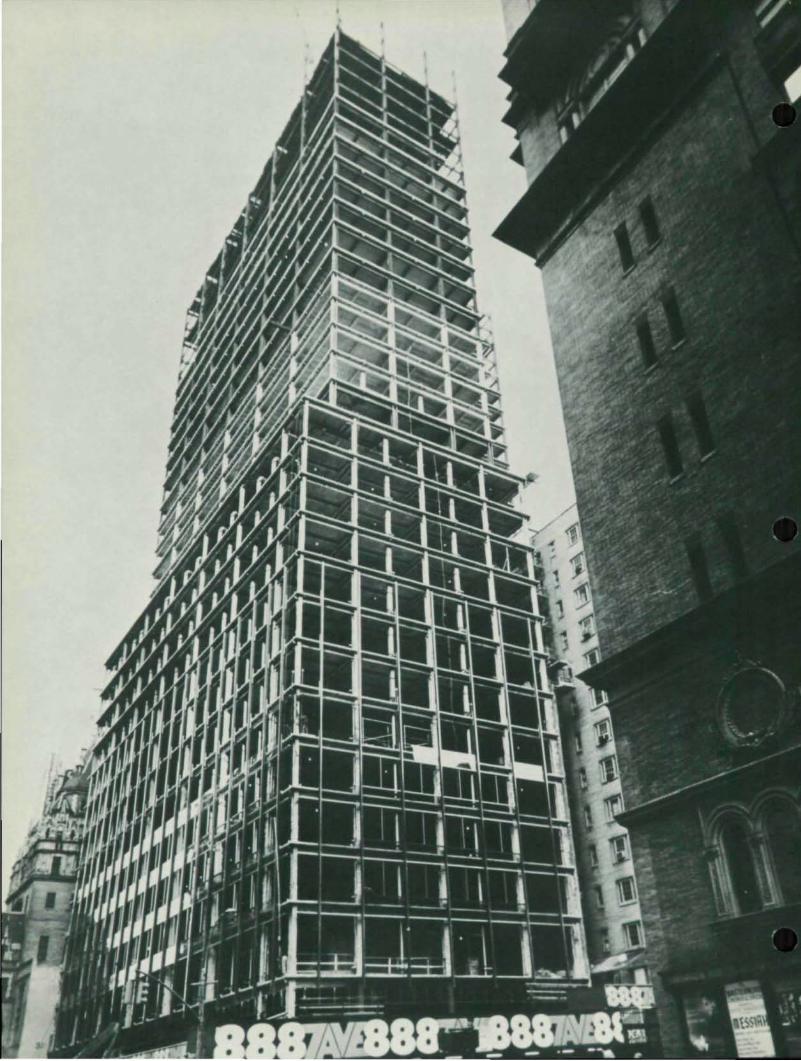
COMPOSITE DESIGN CUTS COSTS by Jacob Grossman, P.E., Sen ior Associate Robert Rosenwasser, Con sulting En gineer New York, N. Y.
Composite steel-concrete design is still a relative newcomer to building construction, although its advantages in bridge work have long been recognized. In designing the structural framing for a 45-story office building now under construction at 888 Seventh Avenue in New York City, the author found that a composite structural system resulted in overall cost savings, lower story height, and reduced construction time.
Maximum spans in the L-shaped building (dictated by an odd·size site) are 30 ft-4 in. between columns. The composite system utilizes corrugated steel Ilcomposite-form" deck with mechanical shear connectors welded to rigid steel framing. The slab is 4'12-in. lightweight concrete (3,000 psi). All horizontal framing members and columns above the 36th floor are A36 steel. Lower columns are A441. Main framing connections are welded, but floor filler beams are machine bolted to the girders.
Advantages of System
Several unusual benefits were the direct result of the choice of framing system:
1. At mid-span, the depth of the girder could be reduced to the same depth as the filler beams, permitting horizontal transfer of ductwork without increasing story height. This saved approximately 30 ft. of building height. (Typical story height is 11'-6" as compared to 12'-2" with a non-composite
FOURTH QUARTER 1969
system.) As a result there was a significant saving in cost for all vertical elements <exterior walls, partitions, risers, etc.). An extra bonus due to the lower building height was the reduction in wind load on the structure.
2. The higher moment of inertia of the composite girders reduced the drift of the building under combined ~ertical and horizontal (wind) loads. This led to additional savings in the cost of the structural steel, since framing member sizes are usually a function of drift rather than section modulus requirements in high-rise structures.
3. The composite system led to further savings in designing the columns for vertical loads, since the K-ratio (effective column length to actual un· braced length) was reduced.
4. Shallower and lighter filler beams were required than with non-composite construction.
Design Con sidera t ions
Figure 1 shows the elevation, moment diagram, and schematic moment of inertia diagram for a typical composite girder. The combined dead, live, and wind moments are shown superimposed.
The moment of inertia (/) of the girder varies as follows:
abo I of non-composite 24WF section be: I of non-composite reduced steel
section cd: I of composite reduced steel section de: I of composite 24WF section
13

COL.UMN -
c:c:INC.. IN ~eaoN -~..".~ 'N o::'Jf'o1f1i1:)6 lTe. K,.TION
d e
~
14
r'-
I ,
I
I,..
I.
~< r -
~
co. b c: d
t t4 W' j 1f (1'<»lT (14W' c:c>tm>A-..-uU
N£Q .. TI .... MOMI!NT REGION
, ,
POSITIVE. MOMeNT IlI!GION '\
e
GOMlfNEO MOMCNT QlAGP-AM ( C?e,.AQ + 1.1 vI!. t WI_NO)
ONLY
I MOMENT OF ( KWV!ATIC)
F i(J tLTt 1
,
,
r c.os..UMN
-~StPP'I ClI!NT __ ~TOIU eM) ..
~ 10 ~ OOMII'05IT& ACT'1ON. TUlS w.a::;TH • L
1Cnjlj.. tole, ~ .. ....... """"""'" IlEQO • .!.. • ( ... ) I..<
- CONc::.uT1!. ''''' ~Tl~IN
COM,.!ltESSION IItI.u:J COMfiI06,TE. .toCTlOft,l.
""- b -~
r
Figurt!
CX>I-UMN - - •
'- NOTe~ SlAM "
~,1..N.IG£ IN $-4OP.
Figure 3
•
MODERN STEEL CONSTRUCTION
•
•
•

•
•
•
To alleviate the design complications involved in having a variable moment of inertia member, a computer was used, equating the drift to that of a constant moment of inertia beam. It was found that an average moment of inertia calculated as
I.~ = ' .0 X ' .0 + ' be X ' bC + '.e
would give conservative results. (Actual drift is about 90% of the drift obtained by using an average I for the girder considered.) This is partially due to the redistribut ion of wind moments; a larger proportion acts on the composite section adjacent to the column (in the positive moment zone) as compared to the section in the negative moment zone, where the girder does not act compositely.
Fabrication and Erection
In his design the structural engineer provided for two alternate methods of fabrication and erection. The choice was left to the fabricator-erector. One method (which was not selected) calls for each girder to be fabricated as 3 separate units - two deep rolled sections and one shallow rolled section. The deep girder units were to be shop-welded to each side of the columns - two stories high. The shallow girder unit was to be dropped between the outriggers and field welded. Figure 2 illustrates the method. The moments and shears at the outrigger ends would be much smaller than at the columns, and would require smaller field connections.
Figure 3 illustrates the method chosen by the fabricator-erector. The gi rder was fabricated in the shop as a single unit. The bottom portion of the girder was notched at mid-span and a bottom flange was rewelded to the web (the cut-off portion was utilized elsewhere in the structure). The girder was shipped loose and welded to the column in the field. This method required additional steel, which increased the weight of the structural steel to 18 Ibs./sq ft, as compared to about 16 Ibs/ sq ft, but in the judgment of the fabricator-erector, resulted in a lower total cost for the framing in place.
The building is scheduled for completion in late 1970.
FOURTH QUARTER 1969
Architect, Emery Roth & Sons, New York, New York Engineer: Robert Rosenwasser, Consulting Engineer
New York , New York General Contractor: Goodnor Construction Corp.
Long Island City, New York Fabricator: Grand Iron Works, Inc.
Bronx, New York
57'" STReeT
-r-. '''''"'~;!.=''l __ -. I - ,u
! I I J
b • l .. • • ·1
.xl IL . ~
>< j ><l A 'l ,:J"~~_ 1
Ix l x l; J----;. [x l ' J~
, " I ~-
1_",- -.1 , [ ~ 1 ~ -
I .L- I ;:r",,,, I'T
" .. . , ~.
-
l I
Ii -1 II
hi '. ~J j~
. " I ' I
51 4J . ,....4' • 1 t---i ----..-- - ~ • t ~ -il -- _.1_ =-t ___ ~ ___ -L ____
~ ....... ...... "" .. -L ......... . ,. - "" • __ _ II 1 I
-----L ------::_Oic.rr ''''II.:;
5~ Til STReET
, '" Q
J5

AMERICAN INSTITUTE OF STEEL CONSTRUCTION 101 Park Avenue New York, New York 10017
Address Correction Requested
BULK RATE U.S. POSTAGE
PAlO DANBURY, CONN. PERMIT NO. 97 •
•
•