1. overview - general mills...
TRANSCRIPT
ControlLogix Programming StandardProgramming Standards
Overview
CIS_401_ControlLogix_Programming_Standard_WHQ.doc, Revision 2, December 2007 1
ControlLogix Programming Standard This document provides standards for developing Logix-5000 software applications for General Mills (GMI) manufacturing facilities.
These requirements apply to all Logix 5000 control systems used in GMI manufacturing facilities, including software development, testing, implementation, and long-term support. In addition, it applies to equipment from original equipment manufacturers (OEMs), including custom machines and process equipment. OEMs shall ensure that their equipment interfaces correctly with GMI systems, regardless of OEM programming standards.
Table of Contents 1. Overview
2. Programming Software
3. Project Organization
4. Naming Conventions
5. Configuring I/O Modules
6. Memory Configuration and Mapping
7. Networking and Communications
8. Development Procedures
9. Documentation Requirements
10. References and Related Documents
11. Acronyms, Abbreviations, and Mnemonics
12. Revision Summaries
1. Overview The standards described in this document are mandatory unless otherwise identified as optional or preferred. Any variance from GMI requirements or preferences requires prior GMI Engineering approval. Obtain approval from the engineer that issued this document or has been designated as responsible for project deliverables. GMI will provide and document specific project requirements and approvals.
NOTE: If any standards in this document conflicts with standards required by the plant, please inform the plant immediately.
This document includes sample code, which requires modification appropriate to the project. Programmers shall ensure that all code provided for a project, including any modifications to code in this document, functions correctly and interfaces correctly with all pertinent GMI systems.
ControlLogix Programming StandardProgramming Standards
Overview
CIS_401_ControlLogix_Programming_Standard_WHQ.doc, Revision 2, December 2007 2
In addition, the following terminology is used in this document
• Shall: designates unconditional requirements.
• Should: implies a preferred requirement.
• Programmer: the developer responsible for Logix-5000 programming.
1.1 Program Design Control software performs machine and system control. These programming standards aid in the development of control applications that plant technicians can easily understand, maintain, and change. The standards emphasize carefully planned structure, simplicity, clarity, and documentation.
1.2 Access Requirements Programmers and developers shall NOT provide any software that uses password protection, or any type of encryption, that would limit GMI’s access, excepting off-the-shelf software such as operating systems.
The programmer shall provide documented source code for all systems. GMI requires special permission to apply password protection to the code.
ControlLogix Programming StandardProgramming Standards
Overview
CIS_401_ControlLogix_Programming_Standard_WHQ.doc, Revision 2, December 2007 3
1.3 Programming Standards General Mills strongly encourages use of its Control Library, a standard collection of configurable, pre-tested modules for basic control functions such as discrete inputs and outputs, across-the-line motors, on/off valves or devices, VFD controlled motors, analog inputs and outputs, PID controllers, unit operation control, and PLC time coordination. The library includes ControlLogix code and user-defined type (UDT) templates along with Wonderware InTouch tag templates, overlays, and scripts. Contact the GMI project engineer to obtain the Control Library and its documentation.
The General Mills CIS group is also developing standard application routines. Currently, this includes a weighing routine using the Hardy 1756HI-WS module. Contact the GMI electrical project engineer for information.
1.4 HMI Requirements HMI applications are outside the scope of this document. However, most applications being developed based on these standards will interface with a Wonderware HMI system. The Wonderware systems in turn are integrated into a higher level supervisory system (SCADA – Supervisory Control and Data Acquisition). Due to complex design considerations and functionality requirements all HMI systems shall adhere to GMI’s Wonderware Application Frameworks.
ControlLogix Programming StandardProgramming Standards
Programming Software
CIS_401_ControlLogix_Programming_Standard_WHQ.doc, Revision 2, December 2007 4
2. Programming Software Applications shall be developed using Rockwell’s RS-series software products. These include RSLogix-5000, RSLinx, RSNetworx for ControlNet, and RSNetworx for DeviceNet. The system’s overall design dictates which products are used. Generally, you should use the latest released version. However, factors that affect software selection include:
• Compatibility between products
• Compatibility between other GMI systems (such as MASS)
• Revision of other ControlLogix systems on the same project.
• Installed base of ControlLogix systems within the host facility.
• Stability of current releases.
• Required functionality such functions and features not available in the current release that will be available in the next release (depends on project timing and Rockwell’s schedule for future releases).
A complete listing of software used to develop the overall application shall be provided to the Project Manager, Electrical and Control Engineer, and the plant’s engineering department prior to commissioning the system. The listing should include catalog number, description, revision, and comments relating to any special configurations and or requirements.
2.1 Revisions The software revision of RSLogix-5000 shall match the hardware’s firmware revision. When determining which version of hardware and software to use, the design engineer shall consult with GMI’s Project Manager, Electrical and Control Engineer, and the plant’s engineering department prior to starting application development.
When changing revisions during development or commissioning of an application, make sure all application files are properly backed-up and that all hardware within the system is compatible with the proposed version. Always inform the project team and host facility before performing upgrades.
ControlLogix Programming StandardProgramming Standards
Project Organization
CIS_401_ControlLogix_Programming_Standard_WHQ.doc, Revision 2, December 2007 5
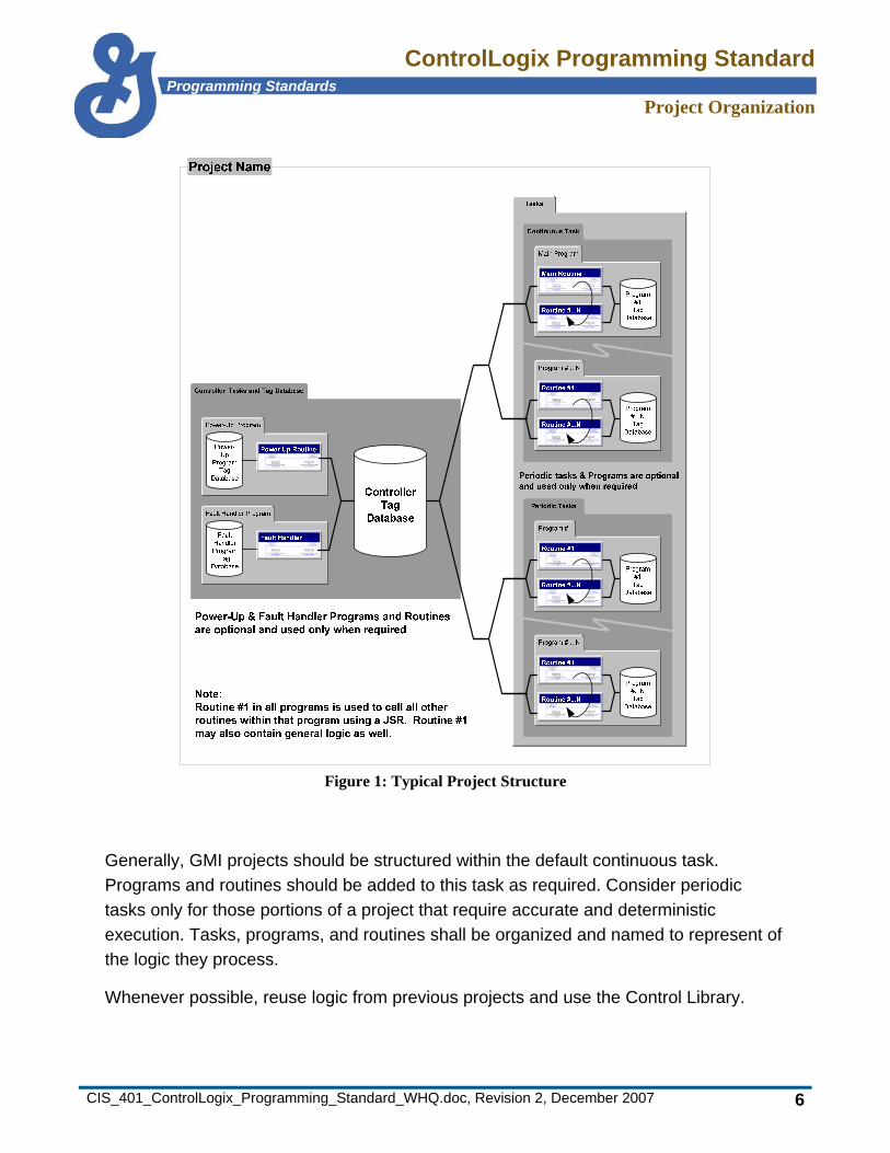
3. Project Organization ControlLogix projects are structured into tasks, programs, and routines—the containers used for organizing an overall project.
• Task—A Scheduling mechanism for executing programs
• Program—A set of related routines and tags
• Routine—Programmer developed code written in a single programming language.
By default, each project contains one continuous task, one main program, and one main routine (Figure 1). The default project also contains power-up and fault handling programs, however, routines must be added. Depending on project requirements, periodic tasks may also be added.
ControlLogix Programming StandardProgramming Standards
Project Organization
CIS_401_ControlLogix_Programming_Standard_WHQ.doc, Revision 2, December 2007 6
Figure 1: Typical Project Structure
Generally, GMI projects should be structured within the default continuous task. Programs and routines should be added to this task as required. Consider periodic tasks only for those portions of a project that require accurate and deterministic execution. Tasks, programs, and routines shall be organized and named to represent of the logic they process.
Whenever possible, reuse logic from previous projects and use the Control Library.

ControlLogix Programming StandardProgramming Standards
Project Organization
CIS_401_ControlLogix_Programming_Standard_WHQ.doc, Revision 2, December 2007 7
3.1 Tasks Tasks shall contain major functions that have similar logic and execution timing requirements. The timing requirement of the functions within the task determines the time period or rate (in milliseconds) within which the task must execute. The importance of the task in relation to other tasks determines the priority level the task should be given. The ability to set the execution rate only pertains to periodic tasks.
The Main Task is a continuous task that is created by default with every new project. The Main Task shall contain the majority of an application’s programs and routines. It should be divided into several program files organized according to a plant area, process, or unit operation. Most projects should retain the default name of “Main Task”. It may also be named “Continuous Task” or a name representative of the programs it contains (such as Mix_System).

ControlLogix Programming StandardProgramming Standards
Project Organization
CIS_401_ControlLogix_Programming_Standard_WHQ.doc, Revision 2, December 2007 8
Periodic Tasks shall be reserved for functions that have very critical scan requirements and programs that have a higher importance than those normally placed in continuous tasks. Examples of programs that may require placement in a periodic task include PID control, motion control, and high speed counting. For clarity, periodic tasks should contain programs and routines of a similar nature. When naming periodic tasks, the last portion of the name shall include the priority and scan rate. In following example, the program has a priority of 1 and a scan rate of 25 milliseconds.
Figure 2: Periodic Task Configuration
ControlLogix Programming StandardProgramming Standards
Project Organization
CIS_401_ControlLogix_Programming_Standard_WHQ.doc, Revision 2, December 2007 9
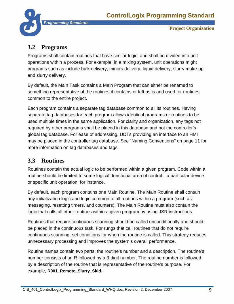
3.2 Programs Programs shall contain routines that have similar logic, and shall be divided into unit operations within a process. For example, in a mixing system, unit operations might programs such as include bulk delivery, minors delivery, liquid delivery, slurry make-up, and slurry delivery.
By default, the Main Task contains a Main Program that can either be renamed to something representative of the routines it contains or left as is and used for routines common to the entire project.
Each program contains a separate tag database common to all its routines. Having separate tag databases for each program allows identical programs or routines to be used multiple times in the same application. For clarity and organization, any tags not required by other programs shall be placed in this database and not the controller’s global tag database. For ease of addressing, UDTs providing an interface to an HMI may be placed in the controller tag database. See “Naming Conventions” on page 11 for more information on tag databases and tags.
3.3 Routines Routines contain the actual logic to be performed within a given program. Code within a routine should be limited to some logical, functional area of control—a particular device or specific unit operation, for instance.
By default, each program contains one Main Routine. The Main Routine shall contain any initialization logic and logic common to all routines within a program (such as messaging, resetting timers, and counters). The Main Routine must also contain the logic that calls all other routines within a given program by using JSR instructions.
Routines that require continuous scanning should be called unconditionally and should be placed in the continuous task. For rungs that call routines that do not require continuous scanning, set conditions for when the routine is called. This strategy reduces unnecessary processing and improves the system’s overall performance.
Routine names contain two parts: the routine’s number and a description. The routine’s number consists of an R followed by a 3-digit number. The routine number is followed by a description of the routine that is representative of the routine’s purpose. For example, R001_Remote_Slurry_Skid.
ControlLogix Programming StandardProgramming Standards
Project Organization
CIS_401_ControlLogix_Programming_Standard_WHQ.doc, Revision 2, December 2007 10
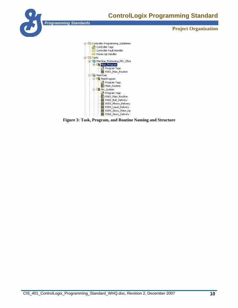
Figure 3: Task, Program, and Routine Naming and Structure
ControlLogix Programming StandardProgramming Standards
Naming Conventions
CIS_401_ControlLogix_Programming_Standard_WHQ.doc, Revision 2, December 2007 11
4. Naming Conventions Use the naming conventions described in the following sections.
4.1 Project and Controller Naming Conventions The project file name and controller names should be representative of a system’s primary control function and should include the machine or system name it is controlling and the controller number in the system.
GMI requires the controller name and project name to be the same. Set the controller name after the project is created. Manually change the controller and project names whenever a name change is needed.
ControlLogix Programming StandardProgramming Standards
Naming Conventions
CIS_401_ControlLogix_Programming_Standard_WHQ.doc, Revision 2, December 2007 12
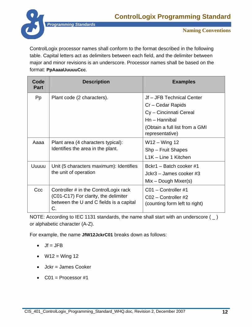
ControlLogix processor names shall conform to the format described in the following table. Capital letters act as delimiters between each field, and the delimiter between major and minor revisions is an underscore. Processor names shall be based on the format: PpAaaaUuuuuCcc.
Code Part
Description Examples
Pp Plant code (2 characters). Jf – JFB Technical Center Cr – Cedar Rapids Cy – Cincinnati Cereal Hn – Hannibal (Obtain a full list from a GMI representative)
Aaaa Plant area (4 characters typical): Identifies the area in the plant.
W12 – Wing 12 Shp – Fruit Shapes L1K – Line 1 Kitchen
Uuuuu Unit (5 characters maximum): Identifies the unit of operation
Bckr1 – Batch cooker #1 Jckr3 – James cooker #3 Mix – Dough Mixer(s)
Ccc Controller # in the ControlLogix rack (C01-C17) For clarity, the delimiter between the U and C fields is a capital C.
C01 – Controller #1 C02 – Controller #2 (counting form left to right)
NOTE: According to IEC 1131 standards, the name shall start with an underscore ( _ ) or alphabetic character (A-Z).
For example, the name JfW12JckrC01 breaks down as follows:
• Jf = JFB
• W12 = Wing 12
• Jckr = James Cooker
• C01 = Processor #1
ControlLogix Programming StandardProgramming Standards
Naming Conventions
CIS_401_ControlLogix_Programming_Standard_WHQ.doc, Revision 2, December 2007 13
4.2 Module Naming Conventions Use the following conventions for naming modules.
4.2.1 Communication Modules and Adapters By default, ControlLogix identifies communications modules and adapters by their catalog number. In addition, module naming shall include rack assignment, slot number (actual slot number when local, and slot number of parent card when remote), node assignment or rack address, and module group information when configuring 1771 I/O. An optional descriptor may be included to identify the adaptor’s purpose (see examples below).

ControlLogix Programming StandardProgramming Standards
Naming Conventions
CIS_401_ControlLogix_Programming_Standard_WHQ.doc, Revision 2, December 2007 14
Use this convention when naming communication modules and adapters: xxxx-xxxxx_aabbcccddMGef.
Code Part Description
xxxx-xxxxx Module Part Number (system defined and generated)
aa Unique ID for local racks (AA-ZZ)
bb Slot number (00-16) Local rack = Number of slot module it is located in Remote rack = Slot number of parent CNB in Local rack
ccc N=Node R=Rack RIO = Remote I/O
dd* Node or rack address of communications module CN= (01-99) DN=(01-63) Remote I/O (00-77 octal)
MG** Module group
e** Starting module group number (0, 2, 4, 6)
f*** Optional descriptor (Examples) Description of rack, i.e., Slurry, Cooker VFD PV = Panelview IC = Industrial computer
* Omit when configuring a 1756-DHRIO communications card ** Omit unless required for 1771 racks configured as ¼, ½ or ¾ rack *** Optional

ControlLogix Programming StandardProgramming Standards
Naming Conventions
CIS_401_ControlLogix_Programming_Standard_WHQ.doc, Revision 2, December 2007 15
Examples:
• 1756-CNB/D_AA01N02 = ControlNet communications module, Node 02 in remote rack AA with parent CNB located in slot 01 of the systems local rack.
• 1771-ASB_AA02RIO05MG4 = Remote I/O adapter connected to a 1756-DHRIO_AA02RIO card located in slot 02 of the systems local rack.
Figure 4: Communication Module and Adapter – Naming convention Examples
4.2.2 I/O Modules—Analog, Discrete, and Specialty By default, ControlLogix identifies modules by their catalog number. In addition, an optional description of the module can be assigned.
Use this convention when naming these modules: xxxx-xxxxx_a
Code Part Description
xxxx-xxxxx Module Part Number (system defined and generated)
a Optional descriptor (Example: Slurry Skid Inputs)
Example:
• 1756-IA16_Slurry_Skid_Inputs = Discrete 16 point 120vAC input card located in slot 1.
The optional descriptors shown below only appear in the I/O configuration area, not the program.
Figure 5: I/O Modules—Analog, Discrete, and Specialty—Naming Convention
ControlLogix Programming StandardProgramming Standards
Naming Conventions
CIS_401_ControlLogix_Programming_Standard_WHQ.doc, Revision 2, December 2007 16
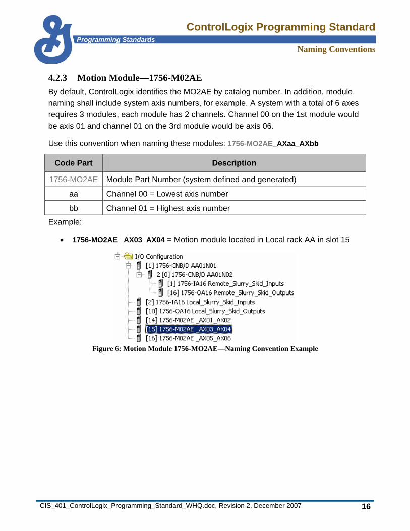
4.2.3 Motion Module—1756-M02AE By default, ControlLogix identifies the MO2AE by catalog number. In addition, module naming shall include system axis numbers, for example. A system with a total of 6 axes requires 3 modules, each module has 2 channels. Channel 00 on the 1st module would be axis 01 and channel 01 on the 3rd module would be axis 06.
Use this convention when naming these modules: 1756-MO2AE_AXaa_AXbb
Code Part Description
1756-MO2AE Module Part Number (system defined and generated)
aa Channel 00 = Lowest axis number
bb Channel 01 = Highest axis number
Example:
• 1756-MO2AE _AX03_AX04 = Motion module located in Local rack AA in slot 15
Figure 6: Motion Module 1756-MO2AE—Naming Convention Example

ControlLogix Programming StandardProgramming Standards
Naming Conventions
CIS_401_ControlLogix_Programming_Standard_WHQ.doc, Revision 2, December 2007 17
4.2.4 Motion Module—1756-M08SE By default, ControlLogix identifies the MO8SE by catalog number. In addition, module naming shall include system axis numbers. For example, a system with a total of 20 axes requires 3 modules, and each module has 8 channels. Channel 00 on the 3rd module would be axis 17 and channel 3 would be axis 20.
Use this convention when naming these modules: 1756-MO8SE_AXaa_AXbb
Code Part Description
1756-MO8SE Module Part Number (system defined and generated)
aa Channel 00 = Lowest axis number
bb Channel <=07 = Highest axis number
Example:
• 1756-MO8SE_AX01_AX08 = Motion module located in Local rack AA in slot 14
Figure 7: Motion Module 1756-MO8SE—Naming Convention Example
ControlLogix Programming StandardProgramming Standards
Naming Conventions
CIS_401_ControlLogix_Programming_Standard_WHQ.doc, Revision 2, December 2007 18
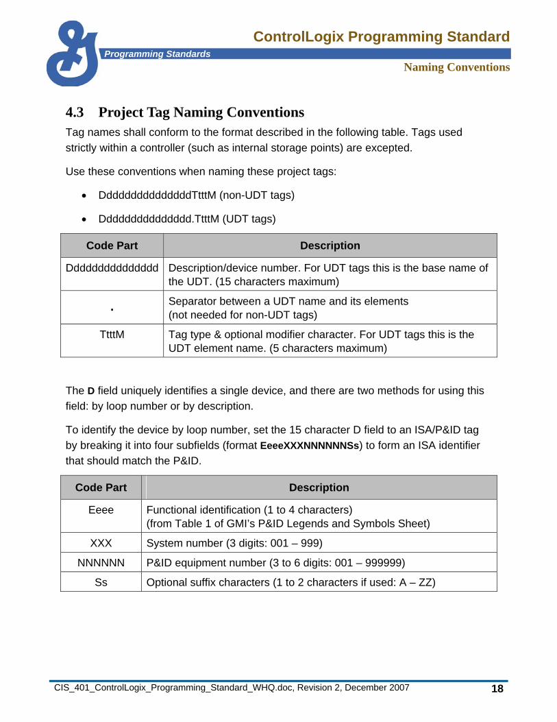
4.3 Project Tag Naming Conventions Tag names shall conform to the format described in the following table. Tags used strictly within a controller (such as internal storage points) are excepted.
Use these conventions when naming these project tags:
• DddddddddddddddTtttM (non-UDT tags)
• Ddddddddddddddd.TtttM (UDT tags)
Code Part Description
Ddddddddddddddd Description/device number. For UDT tags this is the base name of the UDT. (15 characters maximum)
. Separator between a UDT name and its elements (not needed for non-UDT tags)
TtttM Tag type & optional modifier character. For UDT tags this is the UDT element name. (5 characters maximum)
The D field uniquely identifies a single device, and there are two methods for using this field: by loop number or by description.
To identify the device by loop number, set the 15 character D field to an ISA/P&ID tag by breaking it into four subfields (format EeeeXXXNNNNNNSs) to form an ISA identifier that should match the P&ID.
Code Part Description
Eeee Functional identification (1 to 4 characters) (from Table 1 of GMI’s P&ID Legends and Symbols Sheet)
XXX System number (3 digits: 001 – 999)
NNNNNN P&ID equipment number (3 to 6 digits: 001 – 999999)
Ss Optional suffix characters (1 to 2 characters if used: A – ZZ)
ControlLogix Programming StandardProgramming Standards
Naming Conventions
CIS_401_ControlLogix_Programming_Standard_WHQ.doc, Revision 2, December 2007 19
To identify the device by description, use descriptive text in the 15 character D field. The first 1 to 4 characters shall be functional identifiers from Table 1 of GMI’s P&ID Legends and Symbols Sheet. The remaining characters are descriptive.
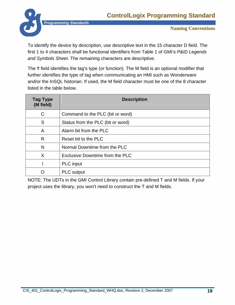
The T field identifies the tag’s type (or function). The M field is an optional modifier that further identifies the type of tag when communicating an HMI such as Wonderware and/or the InSQL historian. If used, the M field character must be one of the 8 character listed in the table below.
Tag Type (M field)
Description
C Command to the PLC (bit or word)
S Status from the PLC (bit or word)
A Alarm bit from the PLC
R Reset bit to the PLC
N Normal Downtime from the PLC
X Exclusive Downtime from the PLC
I PLC input
O PLC output
NOTE: The UDTs in the GMI Control Library contain pre-defined T and M fields. If your project uses the library, you won’t need to construct the T and M fields.

ControlLogix Programming StandardProgramming Standards
Naming Conventions
CIS_401_ControlLogix_Programming_Standard_WHQ.doc, Revision 2, December 2007 20
Tag name examples by loop number:
Example Description
M001002.StrtC Motor 001002 start command from HMI
Xv0121845Aa.OpenS Solenoid valve 121845AA Open status to HMI
Tsh004123.HighA High temperature switch 004123 high alarm to HMI
Tsh004123.ATmr High temperature switch 004123 alarm timer not communicated to HMI
Tag name examples by description number:
Example Description
MDryerExhFan.StrtC Dryer exhaust fan motor start command from HMI
XvFeedDivert.OpenS Feed divert valve Open status to HMI
TshSteamCoil.HighR Steam coil high temperature alarm reset from HMI
TshSteamCoil.ATmr Steam coil high temperature switch alarm timer not communicated to HMI
ControlLogix Programming StandardProgramming Standards
Naming Conventions
CIS_401_ControlLogix_Programming_Standard_WHQ.doc, Revision 2, December 2007 21
4.4 Tag Scope Tags can be generated at both the Controller level and the Program level. Tags generated at the Controller level are “Global” tags and can be used by all programs. Tags generated at the Program level can only be referenced by that program’s routines. When program scoped, tags can have the same names as other programs but be aliased to different I/O. This allows program development to begin before the I/O design has been completed. It also allows multiple copies of the same program to reference the same tag with each tag tied to different I/O. Generic programs may be created and reused within a single application or multiple applications, which reduces development time and provides consistency within and across applications.
4.4.1 Controller Tags Controller tags should be reserved for data required on a global basis, such as across multiple program routines or controllers. This includes tags associated with HMI applications and data that is produced or consumed by other controllers.
4.4.2 Program Tags Program tags should be reserved for data that is required within a single program’s routines. Program scoped tags should have generic I/O or function. This allows programs to be developed with minimal changes once the physical I/O or function has been aliased.
ControlLogix Programming StandardProgramming Standards
Naming Conventions
CIS_401_ControlLogix_Programming_Standard_WHQ.doc, Revision 2, December 2007 22
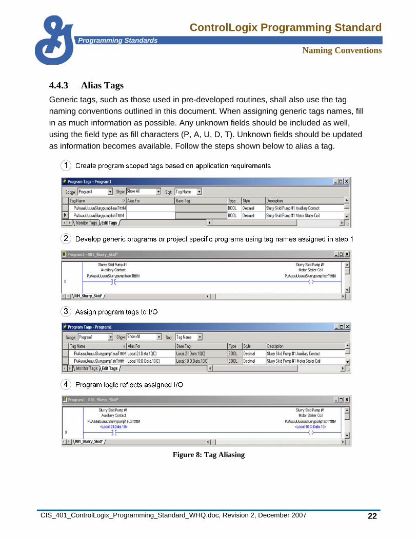
4.4.3 Alias Tags Generic tags, such as those used in pre-developed routines, shall also use the tag naming conventions outlined in this document. When assigning generic tags names, fill in as much information as possible. Any unknown fields should be included as well, using the field type as fill characters (P, A, U, D, T). Unknown fields should be updated as information becomes available. Follow the steps shown below to alias a tag.
Figure 8: Tag Aliasing
ControlLogix Programming StandardProgramming Standards
Configuring I/O Modules
CIS_401_ControlLogix_Programming_Standard_WHQ.doc, Revision 2, December 2007 23
5. Configuring I/O Modules When configuring I/O modules, follow the naming conventions outlined “Naming Conventions” on page 11.
5.1 Electronic Keying Electronic keying for standard input/output modules should be set for Compatible Module. This allows for module replacement with modules having a slightly different revision levels.
When configuring specialty modules, (such as analog, RTD, and VHSC cards) the Electronic Keying selection shall be set to Exact Match. This ensures that a particular revision level will be maintained and that functionality and operation of any replacement module will remain identical.
When set to Exact Match, if you install a module with a different major/minor firmware level, the program prevents the module from establishing a connection with the controller and generates a fault reporting the mismatch. If the firmware is incompatible, the module’s firmware should be flashed to the correct level (up or down) as indicated in the module properties.
ControlLogix Programming StandardProgramming Standards
Configuring I/O Modules
CIS_401_ControlLogix_Programming_Standard_WHQ.doc, Revision 2, December 2007 24
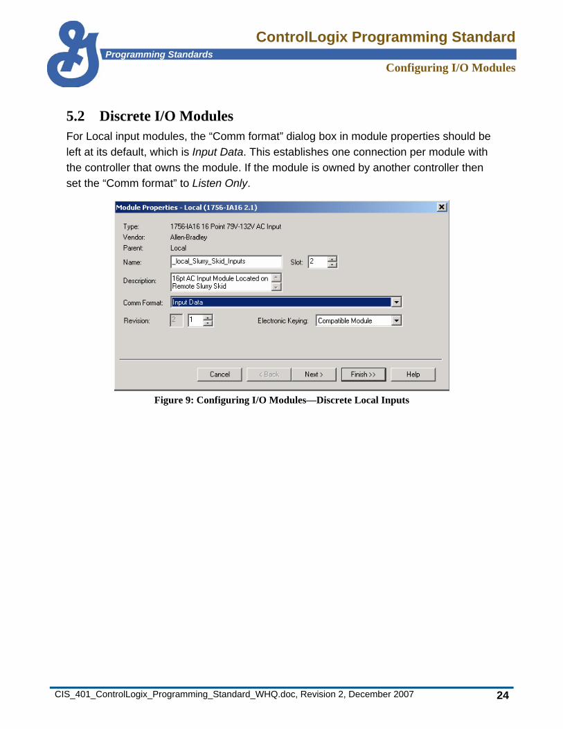
5.2 Discrete I/O Modules For Local input modules, the “Comm format” dialog box in module properties should be left at its default, which is Input Data. This establishes one connection per module with the controller that owns the module. If the module is owned by another controller then set the “Comm format” to Listen Only.
Figure 9: Configuring I/O Modules—Discrete Local Inputs
ControlLogix Programming StandardProgramming Standards
Configuring I/O Modules
CIS_401_ControlLogix_Programming_Standard_WHQ.doc, Revision 2, December 2007 25
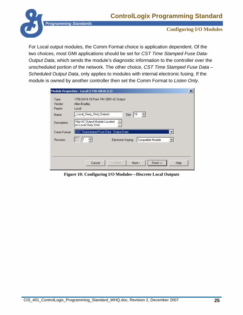
For Local output modules, the Comm Format choice is application dependent. Of the two choices, most GMI applications should be set for CST Time Stamped Fuse Data- Output Data, which sends the module’s diagnostic information to the controller over the unscheduled portion of the network. The other choice, CST Time Stamped Fuse Data – Scheduled Output Data, only applies to modules with internal electronic fusing. If the module is owned by another controller then set the Comm Format to Listen Only.
Figure 10: Configuring I/O Modules—Discrete Local Outputs
ControlLogix Programming StandardProgramming Standards
Configuring I/O Modules
CIS_401_ControlLogix_Programming_Standard_WHQ.doc, Revision 2, December 2007 26
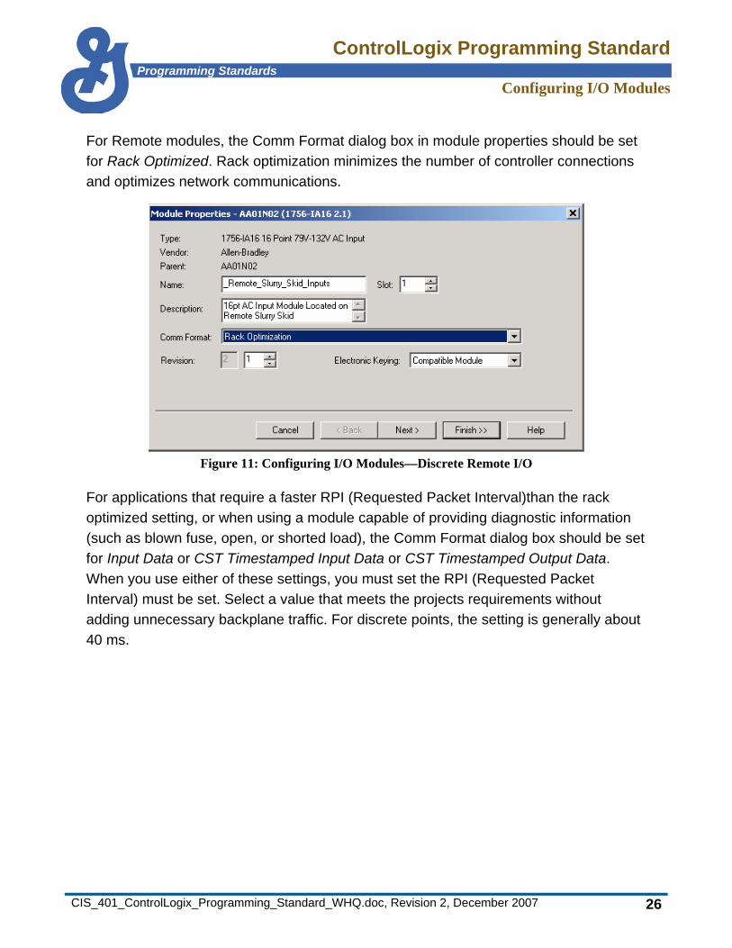
For Remote modules, the Comm Format dialog box in module properties should be set for Rack Optimized. Rack optimization minimizes the number of controller connections and optimizes network communications.
Figure 11: Configuring I/O Modules—Discrete Remote I/O
For applications that require a faster RPI (Requested Packet Interval)than the rack optimized setting, or when using a module capable of providing diagnostic information (such as blown fuse, open, or shorted load), the Comm Format dialog box should be set for Input Data or CST Timestamped Input Data or CST Timestamped Output Data. When you use either of these settings, you must set the RPI (Requested Packet Interval) must be set. Select a value that meets the projects requirements without adding unnecessary backplane traffic. For discrete points, the setting is generally about 40 ms.

ControlLogix Programming StandardProgramming Standards
Configuring I/O Modules
CIS_401_ControlLogix_Programming_Standard_WHQ.doc, Revision 2, December 2007 27
The RPI for modules must be set for a binary multiple of the NUT (Network Update Time). For example, if NUT=5 ms then the RPI must be set for 5, 10, 20, 40, 80, 160, and so on.
Figure 12: Configuring I/O Modules—Setting the RPI for Discrete Modules

ControlLogix Programming StandardProgramming Standards
Configuring I/O Modules
CIS_401_ControlLogix_Programming_Standard_WHQ.doc, Revision 2, December 2007 28
Select Enable Change of State (COS) on all I/O points where high speed update is required or where the update speed needs to be faster than the RPI rate. Change of State updates the entire module data upon any I/O point changing state which was selected for COS. This only applies to input modules in the Local rack.
Figure 13: Configuring I/O Modules—Selecting Change of State for Discrete Modules

ControlLogix Programming StandardProgramming Standards
Configuring I/O Modules
CIS_401_ControlLogix_Programming_Standard_WHQ.doc, Revision 2, December 2007 29
5.3 Analog Modules For analog modules the Comm Format dialog box in module properties should be left at the default setting, which is Float Data. Float Data provides the best resolution and allows engineering units to be used for scaling the analog data. Float Data establishes one connection per module with the controller that owns the module. If the module is owned by another controller, then set Comm Format to Listen Only.
Figure 14: Configuring I/O Modules—Analog Modules

ControlLogix Programming StandardProgramming Standards
Configuring I/O Modules
CIS_401_ControlLogix_Programming_Standard_WHQ.doc, Revision 2, December 2007 30
The Requested Packet Interval (RPI) should set low because Change of State is not a configuration option for analog modules. Generally, this value should be 25 ms.
Figure 15: Configuring I/O Modules—Setting the RPI for Analog Modules
The Real Time Sample (RTS) rate should be set to no less than the RPI for the module. Generally the RTS is set to the same value as the RPI for the module. This ensures that data is sampled at the same rate as the data being sent to the controller.
ControlLogix Programming StandardProgramming Standards
Configuring I/O Modules
CIS_401_ControlLogix_Programming_Standard_WHQ.doc, Revision 2, December 2007 31
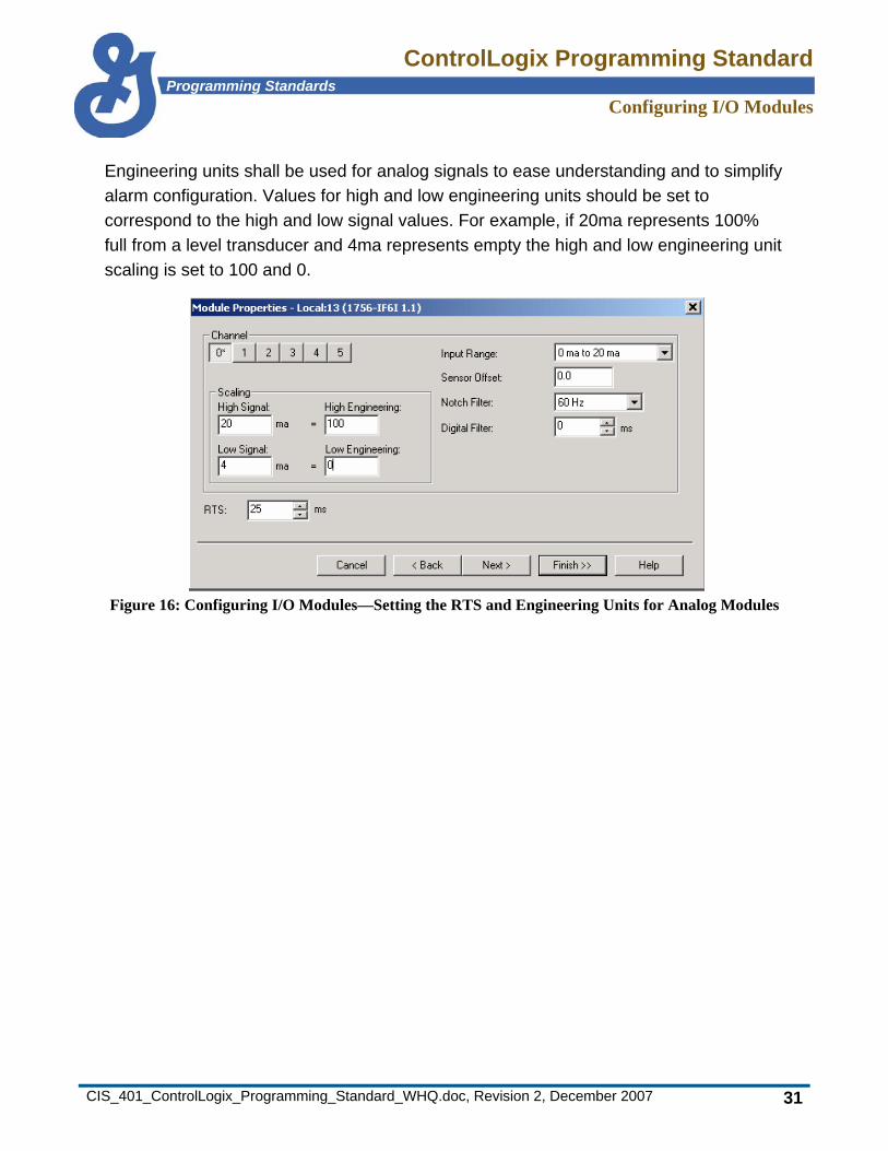
Engineering units shall be used for analog signals to ease understanding and to simplify alarm configuration. Values for high and low engineering units should be set to correspond to the high and low signal values. For example, if 20ma represents 100% full from a level transducer and 4ma represents empty the high and low engineering unit scaling is set to 100 and 0.
Figure 16: Configuring I/O Modules—Setting the RTS and Engineering Units for Analog Modules
ControlLogix Programming StandardProgramming Standards
Configuring I/O Modules
CIS_401_ControlLogix_Programming_Standard_WHQ.doc, Revision 2, December 2007 32
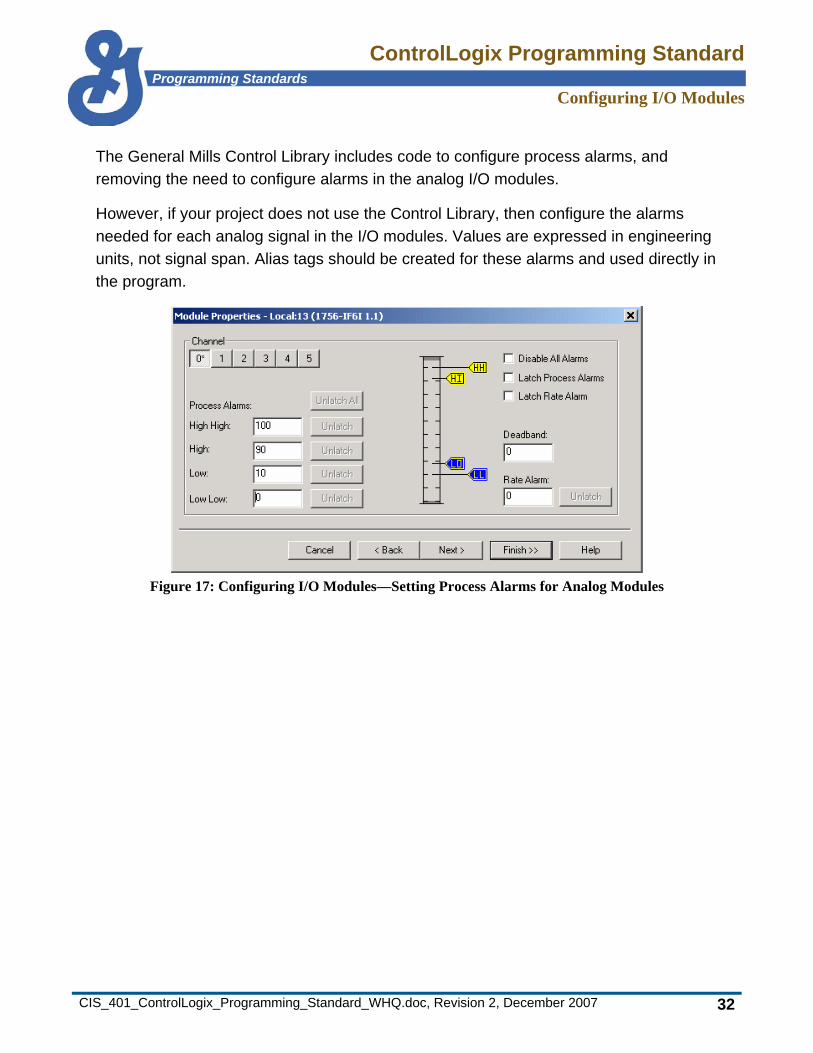
The General Mills Control Library includes code to configure process alarms, and removing the need to configure alarms in the analog I/O modules.
However, if your project does not use the Control Library, then configure the alarms needed for each analog signal in the I/O modules. Values are expressed in engineering units, not signal span. Alias tags should be created for these alarms and used directly in the program.
Figure 17: Configuring I/O Modules—Setting Process Alarms for Analog Modules

ControlLogix Programming StandardProgramming Standards
Memory Configuration and Mapping
CIS_401_ControlLogix_Programming_Standard_WHQ.doc, Revision 2, December 2007 33
6. Memory Configuration and Mapping Data table design should be well-planned and tailored to the specific needs of each project. Data tables should be carefully designed with separate files for logical grouping of data.
For integer data types, GMI prefers DINT rather than INT because of the processor overhead required to convert and display the INT data type as a 16-bit value instead of the native 32-bit format of the Logix controller. Unless required for a legacy system (such as Panelview) the INT data type should be avoided.
Use DINT type tags where bit level manipulation by instructions like FBC, BSL, BSR, and BTD is required. These instructions cannot access BOOL data type arrays. Bits within the DINT shall be aliased and their purpose documented.
Use the enhanced data types where applicable (such as PID or STRING). Avoid placing ASCII strings in DINTs. Ideally, you should never have to change a tag’s style to view the data.
Because of memory inefficiencies, avoid using of integers for storage bit, control relay, or latch relays—use BOOL (bit) instead.
OEM and custom designed systems shall have a controller scoped array or set of arrays, dimensioned as required, created within each program file for data use by higher level systems. It shall contain data or copies of data in a contiguous block. In the absence of specific requirements from the owner, production values, ingredient consumption values, and efficiency measures shall be included. The preferred format for this data is floating point REAL scaled to engineering units.
ControlLogix Programming StandardProgramming Standards
Memory Configuration and Mapping
CIS_401_ControlLogix_Programming_Standard_WHQ.doc, Revision 2, December 2007 34
6.1 Predefined Data Types For clarity and organization, each routine within a program shall have a single dimension array of the TIMER, COUNTER, BOOL, REAL and CONTROL data types. Each of the arrays shall be program scoped. Name these arrays the same as the routine’s name followed by an underscore and the data type (for example, R001_Equipment_Timer). The length of each array should be specific to the needs of the project and the routine’s purpose. Each array shall have generous spares available for program modifications, trouble-shooting, and diagnostic purposes.
Each program file shall also have a single dimension array of the TIMER, COUNTER, BOOL, REAL and CONTROL data types. These arrays shall be controller scoped and will be reserved for use across programs. Naming of these arrays shall be the same as the program’s name followed by an underscore and the data type, e.g., MainProgram_Timer. The length of each array should be specific to the needs of the project and the program’s purpose.
6.2 Nested Arrays Due to the inherent complexity of nested arrays, use them minimally or, if possible, avoid them.
6.3 User Defined Types (UDTs) For clarity and organizational purposes, UDTs shall be used when developing applications that require several instances of the same device or logic. Typically each device must be identical, for example, motor control where the basic logic remains the same and only the device identification changes. The General Mills Control Library uses UDTs and standard logic for devices such as VFDs, FVNR motor starters, and valves. Any modifications to these UTDs require special permission.
Applications that require the creation of new UDTs shall name each element within the UDT using the last two fields of the tag naming conventions—the T and M fields.
ControlLogix Programming StandardProgramming Standards
Memory Configuration and Mapping
CIS_401_ControlLogix_Programming_Standard_WHQ.doc, Revision 2, December 2007 35
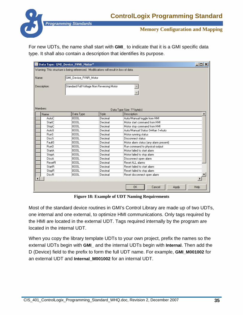
For new UDTs, the name shall start with GMI_ to indicate that it is a GMI specific data type. It shall also contain a description that identifies its purpose.
Figure 18: Example of UDT Naming Requirements
Most of the standard device routines in GMI’s Control Library are made up of two UDTs, one internal and one external, to optimize HMI communications. Only tags required by the HMI are located in the external UDT. Tags required internally by the program are located in the internal UDT.
When you copy the library template UDTs to your own project, prefix the names so the external UDTs begin with GMI_ and the internal UDTs begin with Internal. Then add the D (Device) field to the prefix to form the full UDT name. For example, GMI_M001002 for an external UDT and Internal_M001002 for an internal UDT.

ControlLogix Programming StandardProgramming Standards
Memory Configuration and Mapping
CIS_401_ControlLogix_Programming_Standard_WHQ.doc, Revision 2, December 2007 36
When creating UDTs that require the BOOL data type, the first instance of the BOOL data type within a UDT creates one 32 bit word. Each consecutive BOOL type uses bits within this word for a maximum of 32 BOOL data types. Data types placed between these 32 bit constants consume additional memory. To ensure an efficient use of memory, BOOL data types must be in consecutive order, preferably as the last data type.
Elements within UDTs that interface with real world I/O require additional rungs of programming. These rungs set the element equal to the state of each I/O point. For example, an element named RunS that reflects a motor’s running status requires a single rung of code which turns on or off the RunS element based on the status of the motor starters’ auxiliary contact.
ControlLogix Programming StandardProgramming Standards
Networking and Communications
CIS_401_ControlLogix_Programming_Standard_WHQ.doc, Revision 2, December 2007 37
7. Networking and Communications Use the following standards for networking and communications.
7.1 Ethernet All new installations shall allow for Ethernet connectivity. PLCs should be connected to a separate LAN reserved only for control. This LAN should be segmented via a router from other network segments to prevent unnecessary traffic (for example from office computers). The General Mills standard uses a 172.xxx.xxx.xxx subnet for PLC. Contact the Networking group when setting up a new network to ensure that unique addresses are assigned. Only PLC’s and comparable devices should be connected to this network
Assign static IP addresses to PLCs, rather than relying on BOOTP for address assignment. Each plant is assigned a unique network segment (or segments) to use for their PLCs. In larger plants, several subnets might be needed (for example, 172.25.3.x, 172.25.4.x) Each plant must maintain a single master list of their static PLC addresses to prevent duplications.
ControlLogix Programming StandardProgramming Standards
Networking and Communications
CIS_401_ControlLogix_Programming_Standard_WHQ.doc, Revision 2, December 2007 38
BOOTP is a networking protocol (similar to DHCP in the PC world) which allows devices to be assigned an IP Address and other boot time parameters over the network when they boot rather than requiring them to be hard programmed into the devices. The GMI Standard uses assigned static IP addresses programmed into the devices. This alleviates the need to maintain a BOOTP server. The BOOTP is used for X-terminals at some plants and is also used for PLC’s at some facilities. The use of BOOTP requires the site to maintain a BOOTP server. If a plant chooses to use BOOTP to manage its PLC’s, this is acceptable, but not required, practice.
Use DNS to resolve the IP address for an Ethernet connected device given its name. PLCs do not need to be registered in DNS, as GMI expects any devices needing connectivity to have the actual IP address rather than rely on a name resolution service
Peer-to-peer messaging between multiple processors shall be done using standard MSG instructions. Never send data at a faster rate than required by the application.
At the time of publication, there is a problem with the auto-negotiate feature of the 1756-ENBT modules. They sometimes set themselves to half duplex even though the switch port to which they were connected was full duplex. A work-around that forces the ENBT module’s baud rate and duplex appears in the Rockwell Knowledgebase (Rockwell Tech Note A4193091 – Forcing the Baud and Duplex of a 1756 or 1788-ENBT).
7.2 ControlNet Data transfer between processors in a subsystem that requires determinism (such as interlocking), shall be sent using scheduled messaging or produced and consumed tags. Applications using this type of communications must consider the total number of connections used by the processor. Consider best methods to minimize connection use whenever possible. Never send data at a faster rate than required by the application.
Generally, data is transferred between processors via Ethernet, not ControlNet unscheduled messaging.
ControlLogix Programming StandardProgramming Standards
Development Procedures
CIS_401_ControlLogix_Programming_Standard_WHQ.doc, Revision 2, December 2007 39
8. Development Procedures Base the design and development of Logix control systems on a CSFD (Control System Functional Description). Typically, CSFDs are started during the Feasibility phase and completed during the CPA phase. Large projects involving several systems have one CSFD per system. In most cases, development of the CSFD(s) is the responsibility of the programming team.
8.1 Design Reviews Design review meetings will be scheduled by the project team to provide direction to the programming team and to review their progress. CSFDs will be used as the basis for all design review meetings. The number of reviews and the extent of the invitation list depends on the complexity of the system and the degree to which the system is new or different for the host facility. In any case, the number of reviews required should be determined ahead of time, shall be included in the scope of work, and shall appear in the project’s schedule as milestones.
The objectives for design reviews include:
• Ensure that the completed application meets the expectations of all who will interact with the system and all who have an interest in the functioning of the system (including plant operators; plant maintenance personnel; plant supervisors; plant QA; plant engineering; CIS Engineering; and GMI’s Health, Safety, and Environment Department).
• Ensure that designs are complete and properly tested prior to shakedown and startup.
For applications involving OEM equipment with standard controls system designs or where previous documentation exists, a single design review should be adequate and shall take place prior to purchasing.
Applications requiring custom development shall have several reviews. Generally this will be a four step process consisting of kick-off, 30-, 60- and 90-percent reviews. Fewer reviews may be sufficient (for example, the 30% and 60% reviews are often combined). The number of reviews and the required deliverables for each must be agreed upon and documented ahead of time.
ControlLogix Programming StandardProgramming Standards
Development Procedures
CIS_401_ControlLogix_Programming_Standard_WHQ.doc, Revision 2, December 2007 40
All software shall be developed on machines and storage media that are free from software viruses. Prudent use of virus checking software shall be used throughout the development and implementation process, especially when application files are provided to the project team for review. Suppliers who fail to exercise due diligence in preventing virus infections shall be legally liable for damages.
8.2 Style Requirements Code shall be in ladder format. Function Block programming FB, Structured Text, and SFC’s shall only with prior permission and only if it provides a feature or advantage not achievable with ladder logic.
Straightforward positive logic shall be used. Clever or unconventional programming techniques shall be avoided.
Due to the inherent complexity of indirect addressing, its use should be minimized. It must never be used for direct machine control (such as motor starting). However, for certain applications, usually involving data manipulation, it may be used with discretion.
Software shall include features to deal with a sudden power loss. On power loss, the system shall detect the situation and revert to a safe state that saves all critical values. Be sure to plan for restart at any point in the program. Use of retentive and non-retentive functions shall be carefully considered with power loss and recovery in mind (such as TON versus RTO timers). Both hardware device functions and software logic shall be included in power loss recovery logic. Specifically, some instruments such as scales require an initialization period to function. Likewise, some drives will fault if power is lost and restored too quickly.
The system shall be programmed with comprehensive diagnostics to the HMI system including field device failures, communication failures, battery low, and open field disconnect in addition to process diagnostics.
JMP, MCR, TND, SQI, SQL, SQO, UID and UIE are not permitted and shall not be used.
Loops used for data manipulation (such as arrays), should be used only when required because they consume processor resources heavily. When used, they must be documented in a manner that allows them to be easily understood.
ControlLogix Programming StandardProgramming Standards
Development Procedures
CIS_401_ControlLogix_Programming_Standard_WHQ.doc, Revision 2, December 2007 41
No forces, logical “jumper” branches, temporary end (TND), AFIs or the like shall exist in a finished program. Accordingly, unused and abandoned code shall be removed in the final version.
All data—numeric, digital, scaled or raw—shall reside in the PLC and shall not be stored or manipulated in the HMI system.
Because inputs update asynchronous to the program scan, a copy of the real-world inputs should be made at the beginning of the main routine of the continuous task by examining an input and turning on an internal storage tag that is then used through the entire routine. This technique provides greater control of when portions of an application are executed and prevents unexpected changes from affecting the process. UDTs containing I/O points shall also be set in the main routine of the continuous task.
Logic should avoid techniques that depend on a particular processor, for example, using scan time to time an event that might not work after upgrading to a faster processor.
8.3 Testing and Simulation Requirements OEM equipment applications will be tested during the Factory Acceptance Test (FAT). Scheduling the tests in advance, include the tests in the scope of work, and include the milestones in the project’s schedule. Generally, simulation is not required for these systems because the mechanical tests also test the application.
Applications that require custom development shall be simulated during the Control Software Acceptance Test (CSAT) using CAPE VP Link simulation software. Simulation should be included in the 60- and 90-percent reviews. During the 60-percent review, the simulation shall be complete enough to simulate critical functionality. The objective is to determine if basic concepts conceived early in the design phases are valid. During the 90-percent review, simulation shall be representative of the entire system including process graphics, alarms, and complete interaction with the HMI system. Also, simulation programs will aid in operator training prior to start-up and production.
GMI has a licensing agreement with Cape Software which allows engineering firms doing work for GMI the right to use VP Link simulation software on a per-project basis. Use of the software for any other purpose other than a GMI project is prohibited. Detailed information on VP Link may be obtained by visiting Cape’s web site www.capesoftware.com. Firms interested in obtaining VP Link for use on a GMI project should contact the GMI project engineer.
ControlLogix Programming StandardProgramming Standards
Development Procedures
CIS_401_ControlLogix_Programming_Standard_WHQ.doc, Revision 2, December 2007 42
8.4 Requirements for Version Control and In-Plant Commissioning Activities
Programmers shall adhere to the following requirements during software implementation activities in the plant.
Programmers shall have their own tools. Use of plant equipment requires special permission. Requirements include a notebook computer with either Ethernet or ControlNet communications capability. RS232 may also be used provided the controller’s port is available and not in use. Each computer shall also have the RS applications required to successfully commission the entire system. All applications must be licensed and under current support by Rockwell Software.
When using Ethernet or ControlNet for programming the plant shall supply and approve the ControlNet Node or IP address.
While under development, a single owner shall be designated for each piece of software. The owner shall keep the master copy, where all development and documentation activity takes place. When several developers are simultaneously working on the same piece of software, deliberate care by the owner shall be made to ensure that the master copy reflects all current modifications. Any transfer of ownership shall be done in a careful and deliberate manner to ensure no conflicts and no loss of documentation.
The owner shall make and maintain backup copies at appropriate times during the development period. Never risk more than one hour of programming time.
When the system is put into service, the software owner is responsible for providing the host facilities engineering representative with plant masters on a weekly basis and when leaving the facility.
Several GMI facilities use MDT’s MASS AutoSave system. Systems being commissioned within these facilities must use MASS to make all programming changes. Requirements for physically connecting and accessing MASS must be obtained from the facilities engineering department.
ControlLogix Programming StandardProgramming Standards
Development Procedures
CIS_401_ControlLogix_Programming_Standard_WHQ.doc, Revision 2, December 2007 43
Any time code has been modified, the programmer shall validate modifications the next time the system operates. If practical, all modifications shall be tested at the time of implementation. Plant operating personnel shall be kept thoroughly informed throughout the entire validation period. Be sure to save the previous version as a backup so that you can revert to it if needed.
On-line programming during production is generally permitted and is often needed to prevent downtime. Safety is of prime importance while doing on line edits and shall not be compromised. The proper plant people must be informed while on-line modifications are taking place and any required permission must be obtained for on-line programming.
A plant’s engineering representative shall participate in any software changes made remotely.
At the conclusion of the programming and commissioning activities, owner status shall be returned to the plant. Supplying final, completely documented code (see “Documentation Requirements” on page 44) shall be part of the return process. The programmer shall work deliberately and carefully with the designated plant engineering representative to accomplish the transfer.

ControlLogix Programming StandardProgramming Standards
Documentation Requirements
CIS_401_ControlLogix_Programming_Standard_WHQ.doc, Revision 2, December 2007 44
9. Documentation Requirements Documentation issues during software development include:
• Maintenance of the equipment (particularly advanced troubleshooting)
• Thorough understanding of the operation of the equipment
• Future process modifications and process improvements
• Facilitation of data transfer to a HMI system
The programming and documentation software packages for control devices are seldom complete enough to fully document all aspects of a system. The control engineer must supply standard documentation and supplementary drawings, tables, diagrams, and text to document all parts of the system.
Program documentation shall be consistent with descriptions used on electrical schematics.
All documentation shall be delivered in both electronic format and hard copy. All hard copies shall be 8.5 x11 inch, in portrait format.
Documentation shall written in sentence case (using lower and upper case fonts) and all capital formatting reserved for emphasis. Do NOT write documentation with the Caps Lock key on.
Abandoned documentation (such as ladder instruction comments) shall be removed in the final version along with unused code. Variables reserved for specific, anticipated, future designs are excepted from this rule.
All applications developed for installations in the United States shall be documented in English. For installations in non-English speaking companies, plan documentation to account for language issues.

ControlLogix Programming StandardProgramming Standards
Documentation Requirements
CIS_401_ControlLogix_Programming_Standard_WHQ.doc, Revision 2, December 2007 45
9.1 Routine Comments Each routine shall start with an extended rung comment at rung 0. It shall contain the following minimum information:
• Short descriptive title
• Control description of the control strategy and objective used in the subroutine. This may be one paragraph or several.
• The parent routine and child routines, if any.
• Description of passed parameters
• Author’s name and the date of revision
Figure 19: Example of Routine Comments
Each subsection in a routine shall include a brief description of the control activity being performed in the subsection. Explain the control strategy if it appears complicated.

ControlLogix Programming StandardProgramming Standards
Documentation Requirements
CIS_401_ControlLogix_Programming_Standard_WHQ.doc, Revision 2, December 2007 46
9.2 Rung Comments Rung comments, although not required for every rung, shall be used to explain each section (often a group of rungs). Accordingly, rung comments shall be used for:
• Describing the use of advanced features including, but not limited to, indirect addressing, complicated math, any instruction using the control variable “R”, and For/Next loops.
• Any use of AFI or a branch jumper even if temporary.
• Any file or instruction that is using an unusual data type such as HEX or BCD.
9.3 Ladder Instruction Comments GMI recognizes the ability of the Logix controller to self-document instructions through the use of tags names. In addition to tag names, GMI requires descriptions for all ladder instructions used within a program’s routines. Descriptions should be kept short and meaningful and should contain information useful in determining the instruction’s purpose.
When documenting ladder instructions for real-world I/O, the description shall match the description used on the electrical schematics. If program development begins prior to the completion of the schematics, the programmer shall be responsible for ensuring the schematics accurately reflect his or her documentation.
ControlLogix Programming StandardProgramming Standards
References and Related Documents
CIS_401_ControlLogix_Programming_Standard_WHQ.doc, Revision 2, December 2007 47
10. References and Related Documents References and related documents include:
• Logix-5000 Configuration Standards
• Control Library for ControlLogix and Wonderware Programmer’s Guide
• Wonderware Application/Shell Frameworks manual
• P&ID Legends and Symbol Sheet (Soc-g-02.pdf)

ControlLogix Programming StandardProgramming Standards
Acronyms, Abbreviations, and Mnemonics
CIS_401_ControlLogix_Programming_Standard_WHQ.doc, Revision 2, December 2007 48
11. Acronyms, Abbreviations, and Mnemonics
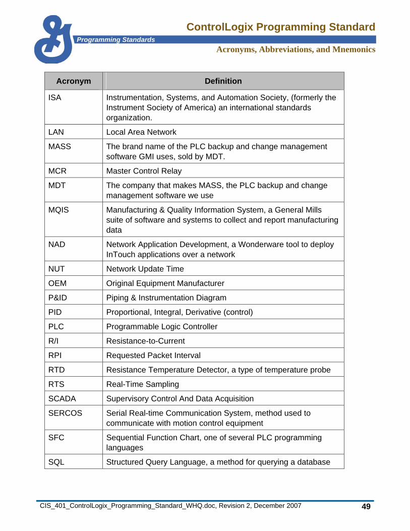
11.1 Acronyms Acronym Definition
ASCII American Standard Code for Information Interchange
BCD Binary Coded Decimal, a type of number coding
BOOL Boolean, a data type
BOOTP Bootstrap Protocol, a method to assign an Ethernet device its network configuration from a host.
CAD Computer-Aided Design
CIS Control & Information Systems, a department of General Mills Engineering
COS Change of State
CSFD Control System Functional Description
DHCP Dynamic Host Control Protocol, a method to dynamically assign an Ethernet device its network configuration
DINT Double Integer, a data type representing a 32-bit integer
DNS Domain Name Server (or Service
ECB Equipment Control Block, A Foxboro block used to communicate with control equipment
FBC File Bit Comparison
FVNR Full-Voltage, Non-Reversing (applies to motors)
HEX Hexadecimal
HMI Human-Machine Interface
I/O Input/Output
InSQL Industrial SQL, the brand name of the historian software GMI uses.
INT Integer, a data type representing a 16-bit integer
IP Internet Protocol
ControlLogix Programming StandardProgramming Standards
Acronyms, Abbreviations, and Mnemonics
CIS_401_ControlLogix_Programming_Standard_WHQ.doc, Revision 2, December 2007 49
Acronym Definition
ISA Instrumentation, Systems, and Automation Society, (formerly the Instrument Society of America) an international standards organization.
LAN Local Area Network
MASS The brand name of the PLC backup and change management software GMI uses, sold by MDT.
MCR Master Control Relay
MDT The company that makes MASS, the PLC backup and change management software we use
MQIS Manufacturing & Quality Information System, a General Mills suite of software and systems to collect and report manufacturing data
NAD Network Application Development, a Wonderware tool to deploy InTouch applications over a network
NUT Network Update Time
OEM Original Equipment Manufacturer
P&ID Piping & Instrumentation Diagram
PID Proportional, Integral, Derivative (control)
PLC Programmable Logic Controller
R/I Resistance-to-Current
RPI Requested Packet Interval
RTD Resistance Temperature Detector, a type of temperature probe
RTS Real-Time Sampling
SCADA Supervisory Control And Data Acquisition
SERCOS Serial Real-time Communication System, method used to communicate with motion control equipment
SFC Sequential Function Chart, one of several PLC programming languages
SQL Structured Query Language, a method for querying a database

ControlLogix Programming StandardProgramming Standards
Acronyms, Abbreviations, and Mnemonics
CIS_401_ControlLogix_Programming_Standard_WHQ.doc, Revision 2, December 2007 50
Acronym Definition
UDT User-Defined Type
UPS Uninterruptible Power Supply
URL Uniform Resource Locator, an address that specifies the location of a file on the Internet
VHSC Very High Speed Counter
VFD Variable Frequency Drive
WAN Wide Area Network
XML Extensible Markup Language, a format for structured document interchange on the Web
11.2 Abbreviations Abbreviation Definition
Hz Hertz
ma milliampere
ms millisecond
VAC AC (alternating current) voltage
VDC DC (direct current) voltage
ControlLogix Programming StandardProgramming Standards
Acronyms, Abbreviations, and Mnemonics
CIS_401_ControlLogix_Programming_Standard_WHQ.doc, Revision 2, December 2007 51
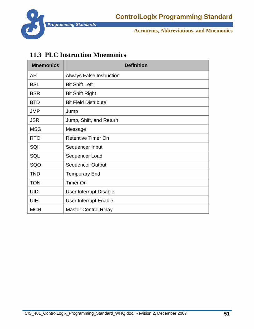
11.3 PLC Instruction Mnemonics Mnemonics Definition
AFI Always False Instruction
BSL Bit Shift Left
BSR Bit Shift Right
BTD Bit Field Distribute
JMP Jump
JSR Jump, Shift, and Return
MSG Message
RTO Retentive Timer On
SQI Sequencer Input
SQL Sequencer Load
SQO Sequencer Output
TND Temporary End
TON Timer On
UID User Interrupt Disable
UIE User Interrupt Enable
MCR Master Control Relay
ControlLogix Programming StandardProgramming Standards
Revision Summaries
CIS_401_ControlLogix_Programming_Standard_WHQ.doc, Revision 2, December 2007 52
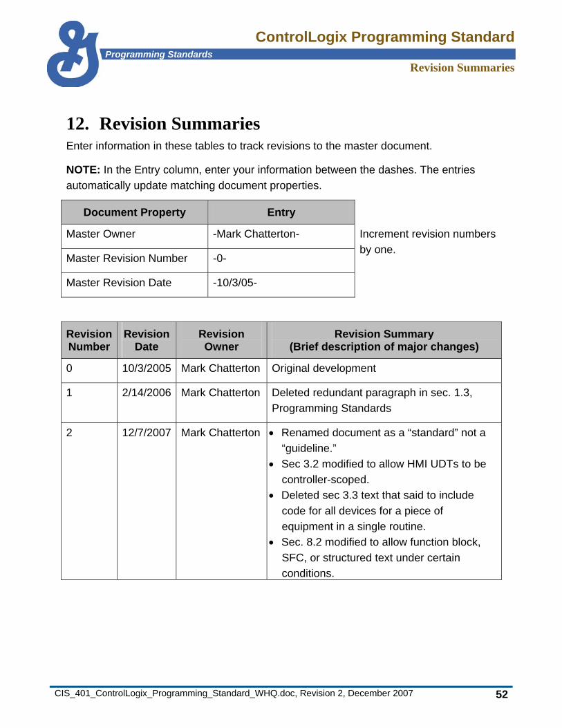
12. Revision Summaries Enter information in these tables to track revisions to the master document.
NOTE: In the Entry column, enter your information between the dashes. The entries automatically update matching document properties.
Document Property Entry
Master Owner -Mark Chatterton-
Master Revision Number -0-
Master Revision Date -10/3/05-
Increment revision numbers by one.
Revision Number
Revision Date
Revision Owner
Revision Summary (Brief description of major changes)
0 10/3/2005 Mark Chatterton Original development
1 2/14/2006 Mark Chatterton Deleted redundant paragraph in sec. 1.3, Programming Standards
2 12/7/2007 Mark Chatterton • Renamed document as a “standard” not a “guideline.”
• Sec 3.2 modified to allow HMI UDTs to be controller-scoped.
• Deleted sec 3.3 text that said to include code for all devices for a piece of equipment in a single routine.
• Sec. 8.2 modified to allow function block, SFC, or structured text under certain conditions.
ControlLogix Programming StandardProgramming Standards
Revision Summaries
CIS_401_ControlLogix_Programming_Standard_WHQ.doc, Revision 2, December 2007 53
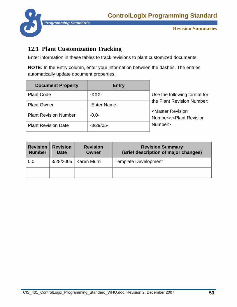
12.1 Plant Customization Tracking Enter information in these tables to track revisions to plant customized documents.
NOTE: In the Entry column, enter your information between the dashes. The entries automatically update document properties.
Document Property Entry
Plant Code -XXX-
Plant Owner -Enter Name-
Plant Revision Number -0.0-
Plant Revision Date -3/29/05-
Use the following format for the Plant Revision Number:
<Master Revision Number>.<Plant Revision Number>
Revision Number
Revision Date
Revision Owner
Revision Summary (Brief description of major changes)
0.0 3/28/2005 Karen Murri Template Development