1) outline of fukushima dai-ni nuclear power station · chapter (3) situation of fukushima dai-ni...
TRANSCRIPT

(3) Situation of Fukushima Dai-ni Nuclear Power Station
1) Outline of Fukushima Dai-ni Nuclear Power Station
Fukushima Dai-ni Nuclear Power Station (NPS) is located in the towns of Tomioka and
Naraha in Futaba County in Fukushima Prefecture, about 12 km south of Fukushima
Dai-ichi NPS, and faces the Pacific in the east. The shape of the site is roughly square
and the total site area is about 1.47 million m2
(Fig. II-2-84). Since the commissioning
of Unit 1 in April 1982, Fukushima Dai-ni NPS gradually extended its facilities, and at
present it consists of a total of four reactors, with a total generating capacity of 4,400
MW (Table II-2-38).
TableII-2-38 Power Generation Facilities of Fukushima Dai-ni NPS
Unit 1 Unit 2 Unit 3 Unit 4
Electric output
(10,000 kW) 110.0 110.0 110.0 110.0
Start of construction 1975/11 1979/2 1980/12 1980/12
Commercial operation 1982/4 1984/2 1985/6 1987/8
Reactor type BWR-5
Containment type Mark II Improved Mark II
Number of fuel
assemblies 764 764 764 764
Number of control rods 185 185 185 185
Figure II-2-84 General Arrangement Plan of Fukushima Daini Nuclear Power Station
1号機
2号機
3号機
4号機 Unit 4
Unit 3
Unit 2
Unit 1
Chapter II
II-220

2) Safety design against design basis events at Fukushima Dai-ni NPS
Safety design of the external power supply, emergency power supply system and
cooling functions, etc. against design basis events at Fukushima Dai-ni NPS, as related
to the recent accident, is as follows.
The external power supply is designed to be connected to the electric power system
through two or more lines. Concerning the emergency power supply system responding
to a loss of external power supply, emergency DGs are installed based on the concept of
redundancy and independence. In addition to this, an emergency DC power supply
system (batteries) is installed in order to address the short-term loss of all AC power
supplies, and thus redundancy and independence have been secured.
High pressure core spray systems (HPCS) and RCIC are also installed as systems to
cool down the core under high pressure condition, in case cooling by a condenser
cannot be achieved. In addition, RHR and low pressure core spray systems (LPCS) are
installed as systems to cool down the core under low pressure condition.
Further, SRV is installed in the main steam pipe connecting to the RPV in order to
discharge reactor steam to S/C. The SRV has a function of automatic de-pressurization.
A comparison of these safety facilities is shown in Table II-2-39, and the system
configuration is shown in Figures II-2-85 to II-2-105.
Seawater supplied by the seawater cooling system is used as the ultimate heat sink at the
heat exchangers in RHR, as is shown in Figures II-2-94 to II-2-102.
For the prevention of hydrogen explosions, a nitrogen atmosphere is maintained inside
the PCV, and a flammable gas control system (FCS) is installed in order to prevent
hydrogen combustion inside the PCV.
Chapter II
II-221

Table II-2-39 Comparison of Engineering Safety Equipment and Reactor
Auxiliary Equipment
Unit 1 Unit 2 Unit 3 Unit 4
Number of systems 1 1 1 1
Flow rate
Unit 1 flow rate(t/h)Units 2-4 pumping rate (t/h)
Total pump head (m) 866~197 Approx.860~Approx.200
Number of pumps 1 1 1 1
Number of systems 1 1 1 1
Flow rate
Unit 1 flow rate(t/h)Units 2-4 pumping rate (t/h)
Total pump head(m) 218 Approx.210 Approx.210 Approx.210
Number of pumps 1 1 1 1
Pumps
Number of Units 3 3 3 3
Flow rate(m³/h/unit) Approx.1,690 Approx.1,690 Approx.1,690 Approx.1,690
Total pump head (m) Approx.92 Approx.86 Approx.92 Approx.92
Heat exchanger
2 2 2 2
Heat transfer capacity (kW/unit)Approx.19.3*103
(Reactor shutdown cooling mode)
Approx.17.0*10 3
(Containment spray cooling mode)
Approx.12.3*103 Approx.12.3*103
Pumps
4 4 4 4
Approx.1,450 Approx.1,460 Approx.1,150 Approx.1,100
Approx.35 Approx.50 Approx.40 Approx.40
Heat exchanger
4 4 4 4
Heat transfer capacityUnits 1,3,4 (kcal/h/unit)
Unit 2 (kcal/h/unit)Approx.8.4*106 6 6 6
Pumps
4 4 4 4
Approx.2,550
Approx.30
Steam turbine
1 1 1 1
Reactor core pressureUnits 1,2 (MPa[gage])
Units 3,4 (kg/cm2g)
Approx.7.86~Approx.1.04
80~10 80~10
Power (kW) Approx.541~Approx.97
Rotation frequency (rpm) Approx.4,500~Approx.2,200
Pumps
1 1 1 1
Flow rate (m³/h) Approx.142
Approx.880~Approx.190Approx.880~Approx.190
Number of systems 2 2 2 2
Number of ventilation fans 2 2 2 2
Capacity
Rate of Iodine removal efficiency of system(%) 99% or more
18 18 18 18
Blowout capacity (t/h/unit) Approx.400 Approx.400 Approx.400 Approx.400
75.2(2units) 7.37(2units)
75.9(4units) 7.44(4units)
76.6(4units) 7.51(4units)
77.3(4units) 7.58(4units)
78.0(4units) 7.65(4units)
79.4(2units) 7.79(2units)
82.6(4units) 8.10(4units)
83.3(4units) 8.17(4units)
84.0(4units) 8.24(4units)
84.7(4units) 8.31(4units)
Blowout location Suppression pool
Residual heat removal and cooling seawater system
(RHRS)
Residual heat removal system
(RHR)
Residual heat removal and cooling
system
(RHRC)
Reactor core isolation cooling system
(RCIC)
Standby gas treatment system
(SGTS)
Blowout pressure(Relief valve function)
Unit 1 (kg/cm2g)Units 2-4 (MPa[gage])
Blowout pressure(Safety valve function)
Unit 1 (kg/cm2g)Units 2-4 (MPa[gage])
Main steam safety relief valve
Fukushima Dai-ni NPS
High pressure core spray system
(HPCS)
Low pressure core spray system
(LPCS)
Approx.1,440Approx.350~Approx.1,580
Approx.1,440 Approx.1,440 Approx.1,440 Approx.1,440
Approx.4250 Approx.5,000 Approx.5,000 Approx.5,000
Number of Units
Number of Units
Number of Units
Number of Units
Number of Units
Number of Units
Number of Units
Flow rate(m³/h/unit)
Flow rate(m³/h/unit)
Total pump head (m)
Total pump head (m)
Total pump head (m)
Unit 1 (m³/h/system)Units 2-4 (Nm³/h/system)
Approx.880~Approx.190Approx.880~Approx.190
Approx.142Approx.142Approx.142
Approx.4,500~Approx.2,200Approx.4,200~Approx.2,200 Approx.4,200~Approx.2,200
Approx.541~Approx.97Approx.660~Approx.125 Approx.660~Approx.125
Approx.30 Approx.30Approx.25
Approx.2,100Approx.2,450 Approx.2,000
Approx.6.0*10Approx.8.4*10 Approx.6.0*10
Approx.860~Approx.200Approx.860~Approx.200
Approx.350~Approx.1,580
Approx.350~Approx.1,580
(Containment spray cooling mode)(Containment spray cooling mode)
99% or more 99% or more 99% or more
7.37(2units) 7.37(2units)
7.44(4units) 7.44(4units)
7.51(4units) 7.51(4units)
7.58(4units) 7.58(4units)
7.65(4units)7.65(4units)
7.79(2units)7.79(2units)
8.10(4units)8.10(4units)
8.17(4units)8.17(4units)
8.24(4units)8.24(4units)
8.31(4units)8.31(4units)
Suppression pool Suppression pool Suppression pool
Approx.7.86~Approx.1.04
Chapter II
II-222

Figure II-2-85 System Diagram of Fukushima Dai-ni Nuclear Power Station Units 1 and 2
Sea
Condenser
Circulating water pump(3 units)
To suppressionpool
RCICpump
Main turbine
Condensate pumps(3 units)
Feedwater pumps(2 turbine-driven units)
SLC pumps
(2 units)
HPCSpump
RHR(A)pump
LPCSpump
RHR(B)pump
RHR(C)pump
From CST and
S/P
From CST
MUWCPumps (3 units)
To HPCS,RCIC,CRD
SLCtank
PLR ※1
Feedwater pumps(2 electric-powered units)
From CST
CRDpumps(2 units)
To RCIC
From MUWCpump
To RHR(A)
Condensate storage tank(CST )
To RHR(B) pump
From PLR(B)
※1 PLR(A) is for Unit 1, PLR(B) is for Unit 2
※2 Unit 1 uses 3 pumps, Unit 2 uses 2 pumps
Sea
Condenser
Circulating water pump(3 units)
To suppressionpool
RCICpump
Main turbine
Condensate pumps(3 units)
Feedwater pumps(2 turbine-driven units)
SLC pumps
(2 units)
HPCSpump
RHR(A)pump
LPCSpump
RHR(B)pump
RHR(C)pump
From CST and
S/P
From CST
MUWCPumps (3 units)
To HPCS,RCIC,CRD
Sea
Condenser
Circulating water pump(3 units)
To suppressionpool
RCICpump
Main turbine
Condensate pumps(3 units)
Feedwater pumps(2 turbine-driven units)
SLC pumps
(2 units)
HPCSpump
RHR(A)pump
LPCSpump
RHR(B)pump
RHR(C)pump
From CST and
S/P
From CST
MUWCPumps (3 units)
To HPCS,RCIC,CRD
SLCtank
PLR ※1
Feedwater pumps(2 electric-powered units)
From CST
CRDpumps(2 units)
To RCIC
From MUWCpump
To RHR(A)
Condensate storage tank(CST )
To RHR(B) pump
From PLR(B)
※1 PLR(A) is for Unit 1, PLR(B) is for Unit 2
※2 Unit 1 uses 3 pumps, Unit 2 uses 2 pumps
Figure II-2-86 System Diagram of Fukushima Daini Nuclear Power Station Units 3 and 4
Sea
Condenser
Circulating water pump(3 units)
To suppressionpool
RCICpump
Main turbine
Condensate pumps(3 high-pressure/3 low-pressure units)
Feedwater pumps(2 turbine-driven units)
SLC pumps
(2 units)
HPCSpump
RHR(A)pump
LPCSpump
RHR(B)pump
RHR(C)pump
From CST and
Suppression pool
From CST
MUWCpumps ※2
To HPCS,RCIC,CRD
SLCtank
PLR ※1
Feedwater pumps(2 electric-powered units)
From CST
CRDpumps(2 units)
To RCIC
From MUWCpump
To RHR(A)
Condensate storage tank(CST )
To RHR(B) pump
From PLR(A)
※1 PLR(A) is for Unit 1, PLR(B) is for Unit 2
※2 Unit 1 uses 3 pumps, Unit 2 uses 2 pumps
Sea
Condenser
Circulating water pump(3 units)
To suppressionpool
RCICpump
Main turbine
Condensate pumps(3 high-pressure/3 low-pressure units)
Feedwater pumps(2 turbine-driven units)
SLC pumps
(2 units)
HPCSpump
RHR(A)pump
LPCSpump
RHR(B)pump
RHR(C)pump
From CST and
Suppression pool
From CST
MUWCpumps ※2
To HPCS,RCIC,CRD
SLCtank
PLR ※1
Feedwater pumps(2 electric-powered units)
From CST
CRDpumps(2 units)
To RCIC
From MUWCpump
To RHR(A)
Condensate storage tank(CST )
To RHR(B) pump
From PLR(A)
※1 PLR(A) is for Unit 1, PLR(B) is for Unit 2
※2 Unit 1 uses 3 pumps, Unit 2 uses 2 pumps
Chapter II
II-223

Suppression chamber(S/C )
HPCSCpump
Condensate storage tank(CST )
MO
MO
Reactor pressure vessel
Reactor containment vessel
HPCSpump
Seawater
HPCSSpump
HPCSCheat exchanger
Mechanical seal coolingBearing oil cooling
Seawater
MO
Suppression chamber(S/C )
HPCSCpump
Condensate storage tank(CST )
MO
MO
Reactor pressure vessel
Reactor containment vessel
HPCSpump
Seawater
HPCSSpump
HPCSCheat exchanger
Mechanical seal coolingBearing oil cooling
Seawater
MO
Figure II-2-87 System Diagram of High Pressure Core Spray System (Units 1 and 3)
Suppression chamber(S/C )
HPCSCpump
Condensate storage tank(CST )
Reactor pressure vessel
Reactor containment vessel
HPCSpump
Seawater
SeawaterHPCSSpumps
HPCSCheat exchanger
Mechanical seal coolingBearing oil cooling
MO
MO
MO
Suppression chamber(S/C )
HPCSCpump
Condensate storage tank(CST )
Reactor pressure vessel
Reactor containment vessel
HPCSpump
Seawater
SeawaterHPCSSpumps
HPCSCheat exchanger
Mechanical seal coolingBearing oil cooling
MO
MO
MO
Figure II-2-88 System Diagram of High Pressure Core Spray System (Units 2 and 4)
Chapter II
II-224

LPCS pump
Suppression chamber(S/C )
MO
MO
Reactor pressure vessel
Reactor containment vessel
RHRC (A)/(C )pump
EECW (A)pump
EECW heat exchanger (A)
Seawater
Bearing oil cooling
Mechanical seal cooling
RHRS (A)/(C )pump
RHRC
heat exchanger
(A)/(C)
Seawater
LPCS pump
Suppression chamber(S/C )
MO
MO
Reactor pressure vessel
Reactor containment vessel
RHRC (A)/(C )pump
EECW (A)pump
EECW heat exchanger (A)
Seawater
Bearing oil cooling
Mechanical seal cooling
RHRS (A)/(C )pump
RHRC
heat exchanger
(A)/(C)
Seawater
Figure II-2-89 System Diagram of Low Pressure Core Spray System (Units 1 and 3)
LPCS pump
Suppression chamber(S/C )
MO
Reactor pressure vessel
Reactor containment vessel
RHRC (A)/(C )pump
EECW (A)pump
EECW heat exchanger (A)
Seawater
Seawater
Bearing oil cooling
Mechanical seal cooling
RHRS (A)/(C )pump
RHRC
heat exchanger(A)/(C)
MO
LPCS pump
Suppression chamber(S/C )
MO
Reactor pressure vessel
Reactor containment vessel
RHRC (A)/(C )pump
EECW (A)pump
EECW heat exchanger (A)
Seawater
Seawater
Bearing oil cooling
Mechanical seal cooling
RHRS (A)/(C )pump
RHRC
heat exchanger(A)/(C)
MO
Figure II-2-90 System Diagram of Low Pressure Core Spray System (Units 2 and 4)
Chapter II
II-225

TurbineMain steam piping
Pump
Condensate storage tank( CST )
Suppression chamber(S/C ) MOMO
MO
MO
MO MO MO
MO
Reactor pressure vessel
Reactor containment vessel
TurbineMain steam piping
Pump
Condensate storage tank( CST )
Suppression chamber(S/C ) MOMO
MO
MO
MO MO MO
MO
Reactor pressure vessel
Reactor containment vessel
Figure II-2-91 System Diagram of Reactor Core Isolation Cooling System (All Units)
Chapter II
II-226
A
B
C
D E F
G H J
QP
NL MK
TR
S
格納容器
主蒸気隔離弁
主蒸気ヘッダ
サプレッションプールへ
RCICへ
E F
原子炉圧力容器
AO
AO
AO
AO
AO
AO
AO
AO
主蒸気逃し安全弁
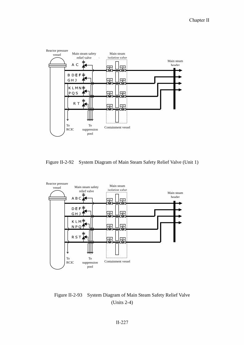
Figure II-2-92 System Diagram of Main Steam Safety Relief Valve (Unit 1)
格納容器
主蒸気隔離弁
主蒸気ヘッダ
サプレッションプールへ
RCICへ
原子炉圧力容器
AO
AO
AO
AO
AO
AO
AO
AO
A B C
D E F
G H J
QPN
L MK
TR S
E F
主蒸気逃し安全弁
Figure II-2-93 System Diagram of Main Steam Safety Relief Valve
(Units 2-4)
Reactor pressure
vessel Main steam safety
relief valve
To
RCIC
To
suppression
pool
Main steam
isolation valve
Containment vessel
Main steam
header
Reactor pressure
vessel Main steam safety
relief valve
To
RCIC
To
suppression
pool
Main steam
isolation valve
Containment vessel
Main steam
header
Chapter II
II-227

EECW熱交換器(A)
RHR(B)ポンプ
RHR(C)ポンプ
RHR(A)ポンプ
原子炉圧力容器原子炉格納容器
MO MO
MO
MO
MO
MO
MO MO
MOMO
MOMO
MO
MO
MOMO
MO
MO
MO
MO
MO
MO MO
MO
MO
MOMO
使用済み燃料プールへ 使用済み燃料プールへ
RHR熱交換器(B)
RHR熱交換器(A)
EECW熱交換器(B)
RHRC(A)/(C) ポンプ
RHRS(A)/(C) ポンプ
海水
EECW(A)ポンプ
MO
海水
RHRC(B)/(D) ポンプ
RHRS(B)/(D) ポンプ
海水
RHRC熱交換器(B)/(D)
EECW(B)ポンプ
海水
EECW(B)ポンプより
EECW熱交換器(B)へ
RHRC熱交換器(A)/(C)←軸受油冷却→
RHR(A)ポンプメカニカルシールへ
RHR(B)/(C)ポンプメカニカルシールへ
Figure II-2-94 System Diagram of Residual Heat Removal System (Unit 1)
EECW熱交換器(A)
RHR(B)ポンプ
RHR(C)ポンプ
RHR(A)ポンプ
原子炉圧力容器原子炉格納容器
MO MO
MO
MO
MO
MO
MO MO
MOMO
MO
MO
MOMO
MO
MO
MO
MO
MO
MO MO
MO
MO
MOMO
使用済み燃料プールへ 使用済み燃料プールへ
RHR熱交換器(B)
RHR熱交換器(A)
EECW熱交換器(B)
RHRC(A)/(C) ポンプ
RHRS(A)/(C) ポンプ
海水
EECW(A)ポンプ
MO
海水
RHRC(B)/(D) ポンプ
RHRS(B)/(D) ポンプ
海水
EECW(B)ポンプ
海水
EECW(B)ポンプより
EECW熱交換器(B)へ
MOMO
RHRC熱交換器(A)/(C) RHRC熱交換器(B)/(D)
RHR(A)ポンプメカニカルシールへ
RHR(B)/(C)ポンプメカニカルシールへ
←軸受油冷却→
Figure II-2-95 System Diagram of Residual Heat Removal System (Unit 2)
To EECW heat
exchanger (B)
Reactor containment vessel
To spent fuel pool Reactor
pressure
vessel
To spent fuel pool
RHRC (A)/(C) pump RHRC (B)/(D) pump
RHRS (A)/(C) pump RHRS (B)/(D) pump
RHRC heat exchanger (A)/(C) RHRC heat exchanger (B)/(D)
To RHR (A) pump
mechanical seal
Seawater Seawater Seawater
RHR (A) pump RHR (B) pump
EECW (A) pump
EECW (B) pump
EECW heat exchanger
(A)
EECW heat exchanger
(B)
Bearing
oil
cooling
RHR (C) pump
RHR heat
exchanger
(A)
RHR heat
exchanger
(B)
To EECW heat
exchanger (B) From EECW
(B) pump
To RHR (B)/(C) pump mechanica seal
Reactor containment vessel
To spent fuel pool To spent fuel pool
RHRC (A)/(C) pump RHRC (B)/(D) pump
RHRS (A)/(C) pump RHRS (B)/(D) pump
RHRC heat exchanger (A)/(C) RHRC heat exchanger (B)/(D)
To RHR (A) pump
mechanical seal
Seawater Seawater Seawater
RHR (A) pump RHR (B) pump
EECW (A) pump
EECW (B) pump
EECW heat exchanger
(A)
EECW heat exchanger
(B)
Bearing
oil
cooling
RHR (C) pump
To EECW heat
exchanger (B) From EECW
(B) pump
Reactor
pressure
vessel
RHR heat
exchanger
(B)
RHR heat
exchanger
(A)
To RHR (B)/(C) pump mechanical seal
Chapter II
II-228

EECW熱交換器(A)
RHR(B)ポンプ
RHR(C)ポンプ
RHR(A)ポンプ
原子炉圧力容器原子炉格納容器
MO MO
MO
MO
MO
MO
MO MO
MOMO
MO
MO
MOMO
MO
MO
MO
MO
MO
MO MO
MO
MO
MOMO
使用済み燃料プールへ 使用済み燃料プールへ
RHR熱交換器(B)
RHR熱交換器(A)
EECW熱交換器(B)RHRS(A)/(C) ポンプ
海水
EECW(A)ポンプ
MO
海水
RHRS(B)/(D) ポンプ
海水
EECW(B)ポンプ
海水
EECW(B)ポンプより
EECW熱交換器(B)へ
MOMO
RHRC熱交換器(A)/(C)
RHRC(A)/(C) ポンプ
RHR(A)ポンプメカニカルシールへ
RHRC(B)/(D) ポンプ
RHRC熱交換器(B)/(D)
RHR(B)/(C)ポンプメカニカルシールへ
←軸受油冷却→
Figure II-2-96 System Diagram of Residual Heat Removal System (Unit 3)
EECW熱交換器(A)
RHR(B)ポンプ
RHR(C)ポンプ
RHR(A)ポンプ
原子炉圧力容器原子炉格納容器
MO MO
MO
MO
MO
MO
MO MO
MOMO
MO
MO
MOMO
MO
MO
MO
MO
MO
MO MO
MO
MO
MOMO
使用済み燃料プールへ 使用済み燃料プールへ
RHR熱交換器(B)
RHR熱交換器(A)
EECW熱交換器(B)
RHRC(A)/(C) ポンプ
RHRS(A)/(C) ポンプ
海水
EECW(A)ポンプ
MO
海水
RHRS(B)/(D) ポンプ
海水
EECW(B)ポンプ
海水
EECW(B)ポンプより
EECW熱交換器(B)へ
MOMO
RHRC(B)/(D) ポンプ
RHRC熱交換器(B)/(D)
RHR(B)/(C)ポンプメカニカルシールへ
RHRC(A)/(C) ポンプ
RHRC熱交換器(A)/(C)
RHR(A)ポンプメカニカルシールへ
←軸受油冷却→
Figure II-2-97 System Diagram of Residual Heat Removal System (Unit 4)
To EECW heat
exchanger (B)
To RHR (B)/(C) pump mechanical seal
To EECW heat
exchanger (B)
To RHR (B)/(C) pump mechanical seal
Reactor containment vessel
To spent fuel pool To spent fuel pool
RHRC (A)/(C) pump RHRC (B)/(D) pump
RHRS (A)/(C) pump RHRS (B)/(D) pump
RHRC heat exchanger (A)/(C) RHRC heat exchanger (B)/(D)
To RHR (A) pump
mechanical seal
Seawater Seawater Seawater
RHR (A) pump RHR (B) pump
EECW (A) pump
EECW (B) pump
EECW heat exchanger
(A)
EECW heat exchanger
(B)
Bearing
oil
cooling
RHR (C) pump
To EECW
heat
exchanger (B) From EECW
(B) pump
Reactor
pressure
vessel
RHR heat
exchanger
(B)
RHR heat
exchanger
(A)
Reactor containment vessel
To spent fuel pool To spent fuel pool
RHRC (A)/(C) pump RHRC (B)/(D) pump
RHRS (A)/(C) pump RHRS (B)/(D) pump
RHRC heat exchanger (A)/(C) RHRC heat exchanger (B)/(D)
To RHR (A) pump
mechanical seal
Seawater Seawater Seawater
RHR (A) pump RHR (B) pump
EECW (A) pump
EECW (B) pump
EECW heat exchanger
(A)
Bearing
oil
cooling
RHR (C) pump
To EECW
heat
exchanger (B) From EECW
(B) pump
Reactor
pressure
vessel
RHR heat
exchanger
(B)
RHR heat
exchanger
(A)
EECW heat exchanger
(B)
Chapter II
II-229
RHR(A)ポンプ
RHRC(A)/(C) ポンプ
原子炉圧力容器原子炉格納容器
圧力抑制室(S/C)
MO
MO
MOMO
MO
MO
RHR熱交換器(A)
RHRS(A)/(C) ポンプ
海水 海水
EECW熱交換器(A)
EECW(A)ポンプ
RHRC熱交換器(A)/(C)
RHR(A)ポンプメカニカルシールへ
軸受油冷却
※B系の構成も同様のため省略
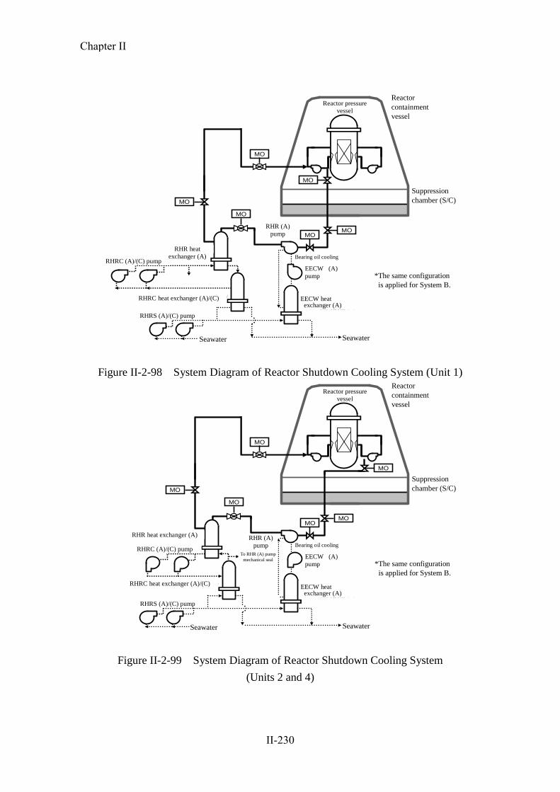
Figure II-2-98 System Diagram of Reactor Shutdown Cooling System (Unit 1)
RHR(A)ポンプ
原子炉圧力容器原子炉格納容器
圧力抑制室(S/C)
MOMO
MO
MO
RHR熱交換器(A)
RHRC(A)/(C) ポンプ
RHRS(A)/(C) ポンプ
海水 海水
EECW熱交換器(A)
EECW(A)ポンプ
RHRC熱交換器(A)/(C)
RHR(A)ポンプメカニカルシールへ
軸受油冷却
※B系の構成も同様のため省略
MO
MO
Figure II-2-99 System Diagram of Reactor Shutdown Cooling System
(Units 2 and 4)
Reactor
containment
vessel
RHRS (A)/(C) pump
RHRC (A)/(C) pump
RHR heat
exchanger (A)
RHR (A)
pump
Reactor pressure
vessel
Suppression
chamber (S/C)
EECW (A)
pump
Bearing oil cooling
RHRC heat exchanger (A)/(C) EECW heat exchanger (A)
Seawater Seawater
*The same configuration
is applied for System B.
Reactor
containment
vessel
RHRS (A)/(C) pump
RHRC (A)/(C) pump
RHR heat exchanger (A) RHR (A)
pump
Reactor pressure
vessel
Suppression
chamber (S/C)
EECW (A)
pump
Bearing oil cooling
RHRC heat exchanger (A)/(C)
To RHR (A) pump
mechanical seal
EECW heat exchanger (A)
Seawater Seawater
*The same configuration
is applied for System B.
Chapter II
II-230

RHR(A)ポンプ
原子炉圧力容器原子炉格納容器
圧力抑制室(S/C)
MOMO
MO
MO
RHR熱交換器(A)
※B系の構成も同様のため省略
RHRS(A)/(C) ポンプ
海水 海水
EECW熱交換器(A)
EECW(A)ポンプ
RHRC(A)/(C) ポンプ
RHRC熱交換器(A)/(C)
RHR(A)ポンプメカニカルシールへ
軸受油冷却
MO
MO
Figure II-2-100 System Diagram of Reactor Shutdown Cooling System (Unit 3)
Reactor
containment
vessel
RHRS (A)/(C) pump
RHRC (A)/(C) pump
RHR (A)
pump
Suppression
chamber (S/C)
EECW (A)
pump
Bearing oil cooling
RHRC heat exchanger (A)/(C) EECW heat exchanger (A)
Seawater Seawater
*The same configuration
is applied for System B.
Reactor pressure
vessel
To RHR (A) pump
mechanical seal
RHR heat exchanger (A)
Chapter II
II-231
原子炉圧力容器 原子炉格納容器
圧力抑制室(S/C)
MOMO
MO
MOMO
MO
※B系の構成も同様のため省略
RHR(A)ポンプ
RHRS(A)/(C) ポンプ
海水 海水
EECW熱交換器(A)
EECW(A)ポンプ
RHRC(A)/(C) ポンプ
RHR熱交換器(A)
RHRC熱交換器(A)/(C)
RHR(A)ポンプメカニカルシールへ
軸受油冷却
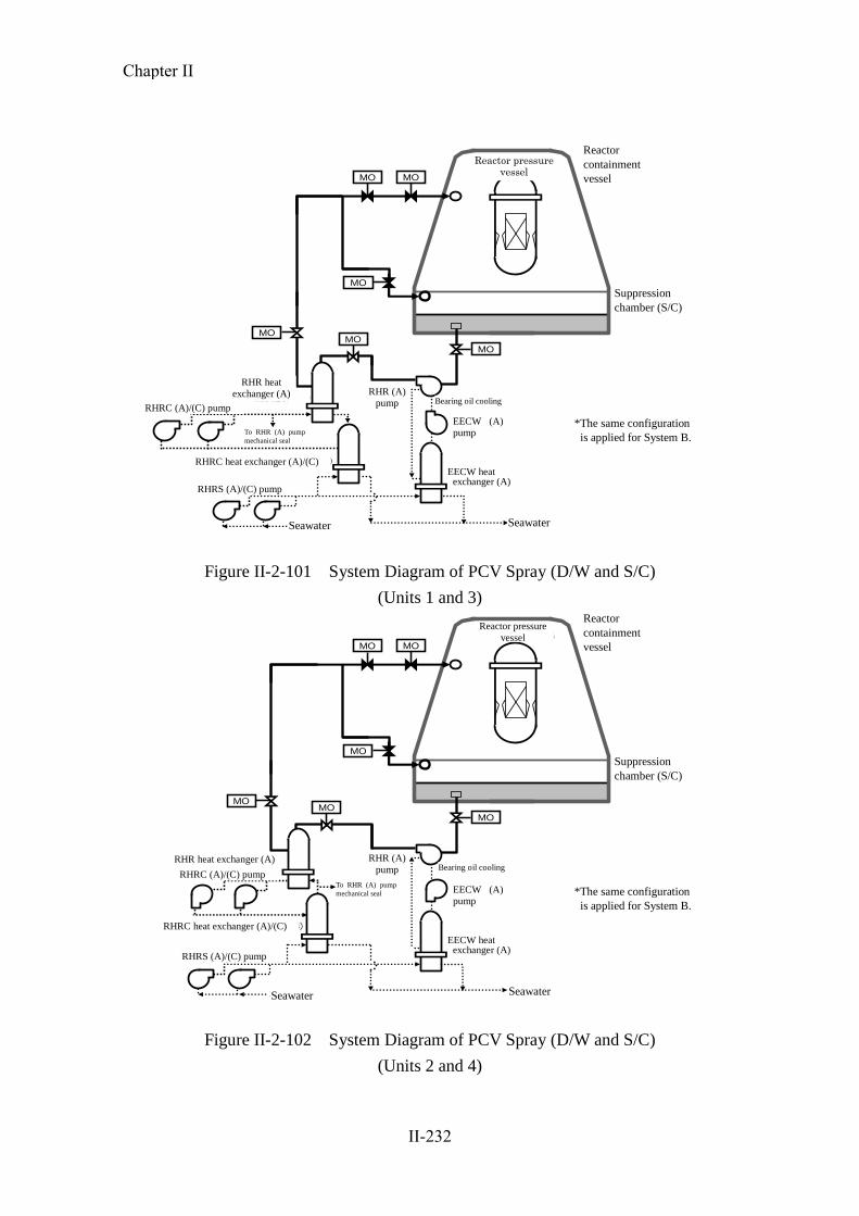
Figure II-2-101 System Diagram of PCV Spray (D/W and S/C)
(Units 1 and 3)
原子炉圧力容器 原子炉格納容器
圧力抑制室(S/C)
MOMO
MO
MOMO
MO
RHR(A)ポンプ
RHR熱交換器(A)
RHRS(A)/(C) ポンプ
海水 海水
EECW熱交換器(A)
EECW(A)ポンプ
RHRC(A)/(C) ポンプ
RHRC熱交換器(A)/(C)
RHR(A)ポンプメカニカルシールへ
軸受油冷却
※B系の構成も同様のため省略
Figure II-2-102 System Diagram of PCV Spray (D/W and S/C)
(Units 2 and 4)
Reactor pressure vessel
Reactor
containment
vessel
RHRC (A)/(C) pump
RHR (A)
pump
Suppression
chamber (S/C)
EECW (A)
pump
Bearing oil cooling
RHRC heat exchanger (A)/(C)
To RHR (A) pump
mechanical seal
EECW heat exchanger (A)
Seawater Seawater
*The same configuration
is applied for System B.
RHRS (A)/(C) pump
RHR heat
exchanger (A)
Reactor
containment
vessel
RHRS (A)/(C) pump
RHRC (A)/(C) pump
RHR heat exchanger (A) RHR (A)
pump
Suppression
chamber (S/C)
EECW (A)
pump
RHRC heat exchanger (A)/(C)
To RHR (A) pump
mechanical seal
EECW heat exchanger (A)
Seawater Seawater
*The same configuration
is applied for System B.
Reactor pressure
vessel
Bearing oil cooling
Chapter II
II-232

RHR(A)ポンプ
原子炉圧力容器
原子炉格納容器
RHR熱交換器(A)
圧力抑制室(S/C)
復水貯蔵タンク(CST)
MUWCポンプ
MO
MO
MO
復水補給水系
RHR系 復水補給水系
消火系
MOMO
MO
MO
RHR(A)系へ
復水補給水系より
低圧注水(A系)
PCVスプレイ
S/Cスプレイ
ろ過水タンク(2基)
ディーゼル駆動
消火ポンプ
電動機駆動
電動機駆動
電動機駆動
各号機共通
MO
MO MO
MO
MO
Figure II-2-103 System Diagram of Alternative (Freshwater) Injection Facilities
(Units 1, 3, 4)
ろ過水タンク(2基)
RHR(A)ポンプ
原子炉圧力容器
原子炉格納容器
RHR熱交換器(A)
圧力抑制室(S/C)
復水貯蔵タンク(CST)
MUWCポンプ
MO
MO
MO MO
MO
復水補給水系
RHR系
ディーゼル駆動
復水補給水系
消火系
消火ポンプ
電動機駆動
電動機駆動
電動機駆動MO
RHR(A)系へ
低圧注水(A系)
PCVスプレイ
S/Cスプレイ
各号機共通
MO
MO
MO
MOMO
MO
復水補給水系より
Figure II-2-104 System Diagram of Alternative (Freshwater) Injection Facilities (Unit
2)
RHR heat exchanger
(A)
RHR (A) pump
Reactor pressure
vessel
Reactor
containment vessel
From condensate
feedwater system
Fire extinguishing
system
Suppression
chamber (S/C)
S/C
spray Condensate
feedwater system
Diesel-driven
Filtrate tanks (2
units)
Common to all
reactors
PCV
spray
LPCI (A)
MUWC pumps
Motor-driven
Motor-driven
Motor-driven
Condensate storage tank
(CST)
Fire extinguishing pump
To RHR (A)
system
RHR system Condensate
feedwater
system
RHR heat exchanger
(A)
RHR (A) pump
Reactor pressure
vessel
Reactor
containment vessel
From condensate
feedwater system Fire extinguishing
system
Diesel-driven
Filtrate tanks (2
units)
Common to all
reactors
LPCI (A)
MUWC pumps
Motor-driven
Motor-driven
Motor-driven
Condensate storage tank
(CST)
To RHR (A)
system
RHR system Condensate
feedwater
system
Condensate
feedwater system
Fire extinguishing pump
PCV
spray
S/C
spray
Suppression
chamber (S/C)
Chapter II
II-233

原子炉圧力容器
原子炉格納容器
主排気筒
原子炉建屋 屋外
ラプチャーディスク
SGTSAO
AO
AO
AO
MO
ボンベ
IA
MO
MO
圧力抑制室(S/C)
MO
IA
ボンベ
AO
MO
IA
ボンベ
Figure II-2-105 System Diagram of PCV Vent (All Units)
Reactor
containment vessel
Reactor pressure
vessel
Suppression
chamber
(S/C)
Outdoor
Cylinder
Cylinder
Cylinder
Rupture disk
Reactor building
Main exhaust
stack
Chapter II
II-234

3) Situation before the earthquake
On the day of the earthquake, all units at Fukushima Dai-ni NPS were under operation
at their rated thermal power.
A total of four external power supply lines, namely, Tomioka Lines No. 1 and 2 (500kV)
and Iwaido Lines No. 1 and 2 (66kV) from Shin-Fukushima Substation were connected
to Fukushima Dai-ni NPS.
At the time of the earthquake, three external power supply lines were available as
Iwaido Line No. 1 was under inspection.
4) Situation from the occurrence of the earthquake to cold shutdown
All the reactors from Units 1 to 4 at Fukushima Dai-ni NPS which had been in
operation were scrammed automatically in response to the earthquake.
A total of three external power supply lines (Tomioka Lines No. 1 and 2 (500kV) and
Iwaido Line No. 2 (66kV)) had been connected to this NPS as Iwaido Line No. 1
(66kV) had been undergoing maintenance. After the earthquake, Tomioka Line No. 2
stopped receiving power because the insulator of the disconnecting device was damaged
at Shin-Fukushima Substation. Meanwhile, Iwaido Line No. 2 stopped at the direction
of the central power supply headquarters due to damage to a lightning arrester of this
same substation. As a result, only Tomioka Line No. 1 remained available and continued
to provide external power to emergency components (Restoration work was completed
at 13:38 on March 12, 2011 and the suspended lines became available one after
another).
The tsunamis caused by the earthquake subsequently struck the Fukushima Dai-ni NPS
site, causing the seawater pumps of Units 1, 2 and 4 to stop functioning, which therefore
resulted in loss of the heat removal function. The ocean side of the NPS was submerged
about 3m, and the main building area was submerged about 2.5m by the tsunamis.
At 18:33 on March 11, judging that a situation corresponding to a special event
provided for within Article 10 of the Special Law of Emergency Preparedness for
Nuclear Disaster had occurred, Tokyo Electric Power Co. (TEPCO) notified the national
and local governments of the situation. Afterwards, the S/C temperature exceeded
Chapter II
II-235

100oC, and the reactor pressure suppression function was lost. In accordance with
Article 15 of the Special Law of Emergency Preparedness for Nuclear Disaster, TEPCO
notified the Nuclear and Industrial Safety Agency and relevant organizations the
occurrence of the “loss of pressure suppression function” event in Units 1, 2 and 4 at
5:22, 5:32 and 6:07 on March 12, respectively.
At Units 1, 2 and 4 of Fukushima Dai-ni NPS, an external power supply had been
secured, and the power distribution panel and DC power supply had not been
submerged by the tsunamis. Therefore, the heat removal function was recovered through
the subsequent restoration work, and the reactor coolant temperature declined to less
than 100oC. In this way, the reactors of Units 1 and 2 reached cold shutdown status at
17:00 and 18:00 on March 14, respectively, with that of Unit 4 reaching it at 7:15 on
March 15. Unit 3 reached cold shutdown status at 12:15 on March 12, without ever
losing the reactor heat removal function.
Fig. II-2-106 shows the height, depth and area of submersion caused by the tsunamis.
Chapter II
II-236

機密性2
Point: 60 O.P. +12.3m (Flooded depth 0.6m)
Seismic isolation building
Point 3: O.P. +14.5m (Flooded depth 2.6m)
Point 23: O.P. +12.5m (Flooded depth 0.6m)
Point 29: O.P. +7.2m (Flooded depth 3.3m)
Point 28: O.P. +7.2m (Flooded depth 3.1m)
Point 30: O.P. +12.6m (Flooded depth 8.6m)
Point 29: O.P. +7.2m (Flooded depth 3.3m)
Point 71: O.P. +12.4m (Flooded depth 0.2m)
Point 22: O.P. +15.9m (Flooded depth 4.1m)
Point 10: O.P. +14.2m (Flooded depth 2.4m)
Point 11: O.P. +13.9m (Flooded depth 2.0m)
Point 12: O.P. +12.6m (Flooded depth 0.7m)
Point 7: O.P. +15.6m
Point 8: O.P. +15.3m
Legends
Flooded height (Flooded depth is in parentheses)
Runup height
Point 23: O.P. +12.5m (Flooded depth 0.6m)
Point 72: O.P. +12.6m (Flooded depth 0.6m)
Point 19: O.P. +13.6m (Flooded depth 1.6m)
Point 21: O.P. +15.3m (Flooded depth 3.5m)
Point 20: O.P. +14.1m or more (Flooded depth 2.2m or more)
Point 9: O.P. +14.4m (Flooded depth 2.2m)
Point 6: O.P. +15.4m (Flooded depth 3.5m)
Point 5: O.P. +18.7m
Point: 67 O.P. +12.7m (Flooded depth 0.7m)
Point 69: O.P. +12.7m (Flooded depth 0.8m)
Point: 61 O.P. +12.3m (Flooded depth 0.5m)
Point 18: O.P. +12.5m (Flooded depth 0.6m)
Point 17: O.P. +12.3m (Flooded depth 0.5m)
Point 16: O.P. +12.6m (Flooded depth 0.7m)
Point 2: O.P. +12.7m (Flooded depth 0.8m)
Point 1: O.P. +13.4m
Point 13: O.P. +12.8m (Flooded depth 0.8m)
Point: 14 O.P. +12.9m (Flooded depth 0.8m)
Point: 15 O.P. +12.8m (Flooded depth 1.0m)
Point: 73 O.P. +12.8m (Flooded depth 0.6m)
Point: 66 O.P. +12.4m (Flooded depth 0.5m)
Point 4: O.P. +15.0m
Point 62: O.P. +12.3m (Flooded depth 0.6m)
Point 63: O.P. +12.1m (Flooded depth 0.5m)
Point 59O.P. +14.5m (Flooded depth 2.6m)
Point: 60.P. +12.1m (Flooded depth 0.3m)
Point 41: O.P. +7.0m (Flooded depth 2.8m)
Point 42: O.P. +7.0m (Flooded depth 3.1m)
Point 40: O.P. +7.0m (Flooded depth 3.0m)
Point 64: O.P. +12.3m (Flooded depth 0.3m)
Point 3: O.P. +14.5m (Flooded depth 2.6m)
Turbine building of Unit 1
Unit 1 Unit 2
Turbine building of Unit 2 Point 58: O.P. +12.1m (Flooded depth 0.3m)
Point: 68 O.P. +12.9m (Flooded depth 1.0m)
Point: 53 O.P. +11.9m (Flooded depth 0.1m)
Point 39: O.P. +7.0m (Flooded depth 3.0m)
Point 37: O.P. +7.1m (Flooded depth 3.1m)
Point 34: O.P. +8.3m (Flooded depth 4.3m)
Point 35: O.P. +7.2m (Flooded depth 2.9m)
Point 36: O.P. +7.1m (Flooded depth 3.1m)
Point 33: O.P. +7.3m (Flooded depth 3.4m)
Point 31: O.P. +7.1m (Flooded depth 3.2m)
Point 32: O.P. +7.1m (Flooded depth 3.2m)
Point 27: O.P. +7.3m (Flooded depth 3.1m)
Point 26: O.P. +7.2m (Flooded depth 3.1m)
Point 49: O.P. +8.9m (Flooded depth 4.3m)
Point 43: O.P. +12.4m (Flooded depth 0.6m)
Point 46: O.P. +10.9m Point 45: O.P. +10.3m
Point 48: O.P. +11.9m
Point 47: O.P. +14.1m
Point 65: O.P. +11.9m
Point 70: O.P. +12.5m (Flooded depth 0.5m)
Turbine building of Unit 3
Point 52: O.P. +12.1m
Turbine building of Unit 4
Unit 4 Unit 3
Max. +9.1 m (Approx. 48 min after earthquake occurrence)
Time (min)
Result of Recurrence Calculation of Tsunami at Fukushima Dai-ni NPS (Water Level Fluctuation near the Tidal Observatory)
Point 56: O.P. +12.0m Point: 54 O.P. +12.0m (Flooded depth 0.2m)
Point 57: O.P. +12.0m Point 24: O.P. +12.1m
Point 25: O.P. +7.9m Point 38: O.P. +10.4m
Point 51: O.P. +11.8m
Point 44: O.P. +11.8m
Point 50: O.P. +11.8m
Tidal observatory: O.P. +4.534m(2007.10)
Flood area (Dashed lines indicate estimation)
Main building area (Site altitude: O.P.+12m)
Seaside area
W
ate
r le
vel
fl
uct
uati
on
(m
)
Figure II -2 -106 Flooded Height, Flooded Depth, and Flooded Area at Fukushima Dai-ni NPS
Chapter II
II-237

a Fukushima Dai-ni NPS Unit 1
Overall conditions immediately after the occurrence of the earthquake
The reactor, which had been under operation at its rated thermal power, was
scrammed at 14:48 on March 11, immediately after the occurrence of the
earthquake, due to excessive seismic acceleration. All the control rods were fully
inserted and the reactor was scrammed properly. It was confirmed at 15:00 on
March 11 that the reactor became subcritical.
Immediately after the reactor scram, voids in the reactor core decreased and the
reactor water level declined to as low as the “reactor water level low (L-3)”. After
that, the reactor water level was recovered by water supplied from the reactor feed
water system without further declining to the level at which the emergency core
cooling system (ECCS) pump and the RCIC automatically actuate.
At 15:36 on March 11, the MSIV was fully closed manually so that the reactor
pressure could be controlled by the SRV in preparation for the situations that the
circulation water pump (CWP) stopped due to the influence of the tsunamis and the
resulting inability to condensate main steam via the condenser, and also that the
turbine gland seal steam was lost, caused by the shutdown of auxiliary boilers due
to the influence of the earthquake.
Following complete closure of the MSIV, the RCIC was manually actuated at 15:36,
and water was injected into the reactor via the RCIC. Then, at 15:40, after
automatic shutdown of the RCIC due to the “reactor water level high (L-8)”, the
reactor water level was adjusted by repeating manual actuation and automatic
shutdown of the RCIC.
Influence of the tsunamis
Because the seawater heat exchanger building was submerged by the tsunamis, it
was judged that all the pumps of emergency equipment cooling systems (residual
heat removal cooling system (RHRC), RHRS, emergency equipment cooling water
system (EECW), high pressure core spray cooling water system (HPCSC) and high
pressure core system cooling seawater system (HPCSS)) failed to be actuated (later,
it was confirmed at the site that some motors and emergency power supply systems
(P/C 1C-2 and 1D-2) became inoperable because they had been inundated). As a
Chapter II
II-238

result, all the ECCS pumps failed to be actuated, and the function to remove
residual heat from the reactor was lost, and hence the decay heat could not be
transferred to the sea, which had been the ultimate heat sink. Under such
circumstances, at 18:33 on March 11, TEPCO judged that the situation
corresponded to the “loss of reactor heat removal function” event in accordance
with Article 10 of the Special Law of Emergency Preparedness for Nuclear
Disaster.
Operations until the establishment of cold shutdown status
Initially, the water was supplied to the reactor by the RCIC. However, from 0:00 on
March 12 onwards, the MUWC, which was an alternate feed water system being
introduced as an AM measure, began to be used in combination with the RCIC.
Rapid depressurization of the reactor was started at 3:50, as the shutdown range in
terms of thermal capacity control was exceeded due to the relation between the
reactor pressure and the S/C water temperature. RCIC was manually stopped at
4:58, due to the fall of steam pressure driving RCIC turbine in association with
rapid depressurization of the reactor. After that, the reactor water level was adjusted
by the alternate feed water by the MUWC.
“Drywell pressure high” (set value: 13.7kPa gage) alarm was issued at 17:35 on
March 11, because the RHR pump failed to cool down the PCV in which
temperature and pressure rose due to operation of the RCIC and the SRV. In
response to the alarm, automatic actuation signals of all the ECCS pumps were
generated. However, the LPCS pump, RHR pump (A) and HPCS pump did not
actuate automatically because the emergency power source units (M/C 1C and
1HPCS) were inoperable. The RHR pumps (B and C) were manually stopped
because the RHRC pumps (B and D), RHRS pumps (B and D) and EECW pump
(B) were inoperable. At this point, measures were taken to prevent further
automatic actuation.
Later, at 5:22 on March 12, as the S/C water temperature exceeded 100oC, it was
judged that the situation corresponded to the “loss of pressure suppression
function” event in accordance with Article 15 of the Special Law of Emergency
Preparedness for Nuclear Disaster (with the S/C water temperature reaching about
130oC at its peak (at 11:30 on March 13)).
Chapter II
II-239
Injection of cooling water (MUWC) into the S/C was started at 6:20 on March 12,
through the cooling water discharge line from the FCS cooler to the S/C.
Meanwhile, alternate water injection into the reactor by the MUWC was switched
to D/W spray at 7:10, and to S/C spray at 7:37, as appropriate, in order to
accomplish alternate cooling of the PCV.
In parallel with these attempts for cooling the reactor, RHRC pump (D), RHRS
pump (B) and EECW pump (B) were inspected and repaired (motors were replaced
for RHRC pump (D) and EECW pump (B)). As the seawater heat exchanger
building of Unit 1 was submerged and the emergency power supply units (P/C 1C-2
and 1D-2) were inundated, temporary cables, which were urgently procured from
outside the NPS, were installed to receive electricity from the power supply unit
(P/C 1WB-1) of the radioactive waste treatment building, supplied by the external
power system, and also from high voltage power supply vehicles, which were also
procured from an off-site organization. In this way, electricity was supplied to
RHRC pump (D), RHRS pump (B) and EECW pump (B) through the temporary
cables, and these pumps were restored and actuated one after another from 20:17 on
March 13 onward.
As RHR pump (B) actuated at 1:24 on March 14, it was judged that the unit had
been restored from the situation corresponding to the event stated in Article 10 of
the Special Law of Emergency Preparedness for Nuclear Disaster (loss of reactor
heat removal function). Also, as a result of cooling the S/C by RHR pump (B), the
S/C water temperature gradually decreased and fell below 100oC at 10:15. Thus, it
was judged that the unit had been restored from the situation corresponding to the
event stated in Article 15 of the Special Law of Emergency Preparedness for
Nuclear Disaster (loss of pressure suppression function).
Furthermore, an implementation procedure was prepared referring to the accident
operation manual, which had been established in advance, in order to promptly cool
down the reactor water, in addition to cooling down S/C water. At 10:05, injection
of S/C water into the reactor through the low pressure coolant injection (LPCI)
system by the RHR pump (B) started. Meanwhile, emergency cooling was
attempted by establishing a circulation line (S/C → RHR pump (B) → RHR heat
exchanger (B) → LPCI line → reactor → SRV → S/C), where, firstly, reactor
water was injected into the S/C via the SRV, secondly, S/C water was cooled by the
Chapter II
II-240

RHR heat exchanger (B) and thirdly, cooled S/C water was injected into the reactor
again through the LPCI line. As a result, the reactor water temperature fell below
100oC at 17:00, and it was confirmed that Unit 1 reached cold shutdown status.
Spent fuel pool
The FPC pump tripped due to the influence of the earthquake (“skimmer surge tank
water level low-low” or “pump’s suction pressure low”). Also, the seawater (SW)
system pumps (A, B and C) of the non-safety service water system were inundated,
and the RCW pumps (A, B and C) on the first basement in the seawater heat
exchanger building were submerged. As these pumps became inoperable and unable
to provide cooling water into the FPC heat exchanger, cooling of the SFP by FPC
could no longer be achieved.
As a result, the SFP temperature rose as high as 62oC at its peak. Water injection
into the SFP through the fuel pool make-up water (FPMUW) system started at
16:30 on March 14. Then, cooling of the SFP by circulating the injected water
started at 20:26 on the same day by the FPC pump (B). Subsequently, cooling of
SFP by the RHR pump (B) started at 0:42 on March 16, and finally at 10:30 on the
same day, the SFP temperature returned to about 38oC, which was the level before
the occurrence of the earthquake.
Containment function
The reactor containment isolation system (hereinafter referred to as “PCIS”) and the
SGTS functioned properly in response to the “reactor water level low (L-3)” signal,
generated at the time when the reactor was scrammed automatically by the “seismic
acceleration high” trip signal at 14:48 on March 11, and the PCV was isolated and
atmospheric pressure inside the reactor building was maintained. Although the PCV
pressure reached as high as about 282kPa gage (on the S/C side) at its peak, it did
not reach the maximum operating pressure of 310kPa gage.
Based on the fact that the PCV pressure was on an upward trend, and assuming that
it would take time to restore the reactor heat removal function, a line configuration
for a PCV pressure resistance ventilation system (a status where the action to open
the outlet valve on the S/C side remained available) was set up.
On-site power supply system
Chapter II
II-241

Immediately after the reactor scram, all on-site power supply systems were
operable. However, due to the subsequent tsunamis, the emergency power supply
system (M/C 1C and 1HPCS) became inoperable because of the submergence of
the reactor building annex, and the emergency power supply system (P/C 1C-2 and
1D-2) became inoperable because of the submergence of the seawater heat
exchanger building. MCC 1C-1-8 lost power because of the inoperability of M/C
1C, and the vital AC 120V power supply distribution board 1A, which had been its
load, shut down and thereby some recorders, etc. became inoperable in the main
control room.
Emergency DGs (A and B systems, and HPCS system) were all operable
immediately after the reactor scram. However, after the tsunami strike, all the
emergency equipment cooling water system pumps failed to be actuated.
Furthermore, as the reactor building annex was submerged due to tsunamis, the
main bodies of the emergency DGs and their accessories (such as pumps, control
panels, MCCs) were inundated, and thus all the emergency DGs became
inoperable.
In the course of the subsequent restoration, the AC 120V vital power supply
distribution board 1A succeeded in receiving power through temporary cables
installed from the temporary power supply distribution board at Unit 2 and became
operable (with restoration work conducted on March 12). Among the load supplied
to the inoperable emergency power supply (P/C 1D-2), RHRC pump (D) and RHRS
pump (B), required for cooling down the reactor and the SFP, secured the power
supply through temporary cables installed from the power supply system of the
radioactive waste treatment building (P/C 1WB-1), and EECW pump (B) secured
the power from a high voltage power supply vehicle (with restoration work
conducted on March 13 and 14).
The main time-series data is shown in Table II-2-40. Statuses of ECCS components,
etc. are shown in Table II-2-41. A schematic view of the plant status is shown in
Figures II-2-107 and 108. The status of the single-line diagram is shown in Figure
II-2-109. Changes in major parameters are shown in Figures II-2-110 and 111.
Chapter II
II-242

Table II-2-40 Fukushima Dai-ni NPS, Unit 1 – Main Chronology (provisional)
* The information included in the table is subject to modifications following later verifications. The
table was established based on the information provided by TEPCO, but it may include unreliable
information due to tangled process of collectinginformation amid the emergency response. As for the view of the Government of Japan, it is expressed in the body text of the report.
3/11 14:46 Earthquake occurred
14:48 All control rods inserted
Automatic reactor shutdown (Trip caused by large earthquake acceleration)
Automatic turbine shutdown
One circuit of Tomioka Line went down (Line 2 tripped, while Line 1 continued receiving electricity)
15:00 Subcritical reactor confirmed
15:22 First wave of tsunami observed (Subsequently, tsunami was observed intermittently until 17:14)
15:33 Circulating water pump (CWP) (C) manually stopped
15:34 Emergency diesel generator (emergency DG) (A) (B) (H) started automatically/immediately stopped due to the impact of tsunami
15:36 Main steam isolation valve (MSIV) closed manually
Reactor core isolation cooling system (RCIC) started manually (Subsequently, start and stop occurred as appropriate)
15:50 Iwaido Line completely went down (Line 2 went down, while Line 1 has already been down for maintenance since before the earthquake)
15:55 Started reactor depressurization (Safety relief valve (SRV) opened automatically) (Subsequently the reactor pressure controlled by automatic or manual opening/closing)
15:57 CWP (A) (B) automatically stopped
17:35 "High Dry Well Pressure" alarm issuedOperator determined that an event to be reported according to Article 10 of the Act on Special Measures concerning Nuclear Emergency Preparedness (reactor coolant leakage) had occurred
(At 18:33, Operator determined that the event was not the reactor coolant leakage)
17:53 Dry well (D/W) cooling system started manually
18:33 Operator determined that an event to be reported according to Article 10 of the Act on Special Measures concerning Nuclear Emergency Preparedness (loss of reactor heat removal function) had occurred
3/12 0:00 Alternative injection using condensate water makeup system (MUWC) started3:50 Started rapid reactor depressurization (Because the heat capacity exceeded the allowable range for operation)
4:56 Completed rapid reactor depressurization
4:58 RCIC stopped manually (Shutdown due to the pressure drop of reactor)
5:22 As the water temperature in the suppression chamber (S/C) exceeded 100℃, Operator determined that an event to be reported according to Article 15 of the Act on Special Measures concerning Nuclear Emergency Preparedness (loss of pressure control function) had occurred
5:58 "Abnormal 10-51 PIP Control Rod" alarm issued
6:20 S/C cooling performed using flammability control system (FCS) cooling water (MUWC)
7:10 D/W spray performed using MUWC (Subsequently it was done as appropriate)
7:37 S/C spray performed using MUWC (Subsequently it was done as appropriate)
7:45 Completed S/C cooling using FCS cooling water (MUWC)
10:21 Started configuration of pressure-proof vent line for reactor containment vessel (PCV)
10:30 "Abnormal 10-51 PIP Control Rod" alarm cleared (Subsequently, issued/cleared several times)Around13:38 One circuit of Iwaido Line received electricity (Line 2 finished recovery)
18:30Completed configuration of PCV pressure-proof vent line
3/13 Around 5:15 Two circuits of Iwaido Line received electricity (Line 1 finished recovery)
20:17 Manually started residual heat removal and cooling seawater system (RHRS) pump (B) (A temporary cable laid down
from 480V standby low voltage switchboard (power center (P/C)) IWB-1, in order to receive electricity)
21:03 Manually started residual heat removal and cooling system (RHRC) pump (D) (Motor replaced/A temporary cable laid down from P/C IWB-1, in order to receive electricity)
3/14 1:24 Manually started residual heat removal system (RHR) (B) (Started S/C cooling mode) As the RHR (B) started, Operator determined that the condition
deemed as an event to be reported according to Article 10 of the Act on Special Measures concerning Nuclear Emergency Preparedness (loss of reactor heat removal function) had become normal
1:44 Manually started emergency equipment cooling system (EECW) (B) (Motor replaced/Received electricity from high voltage power supply vehicle)
3:39 Started RHR (B) S/C spray mode10:05 Started water injection to reactor by RHR (B) low-pressure injection (LPCI) mode10:15 As the S/C water temperature dropped below 100℃, Operator determined that the condition deemed as an event to be reported according to Article 15 of the Act on
Special Measures concerning Nuclear Emergency Preparedness (loss of pressure control function) had become normal
16:30 Started water injection to spent fuel pool (SFP) using fuel pool makeup water system (FPMUW)
17:00 As the reactor water temperature dropped below 100℃, the reactor was put into a state of cold shutdown
20:26 Started circulation operation of fuel pool cooling and purification system (FPC) (B)
22:07 Because Monitoring Post No.1 measured radiation dose in excess of 5 μGy/h (at 0:12 on March 15, Monitoring Post No.3 also measured), Operator determined that an event to be reported
according to Article 10 of the Act on Special Measures concerning Nuclear Emergency Preparedness (increase of radiation dose on the site boundary) had occurred
(It is estimated that the increase in dose was caused by the effect of radioactive material released into the atmosphere due to the accident in Fukushima Daiichi Nuclear Power Station)
3/15
3/16 0:42 Started SFP cooling using RHR (B)
10:30 SFP water temperature became about 38℃ (Returned to water temperature before the earthquake)
3/17 17:22 PCV vent ready state restored to normal state
3/18
3/19 15:28 Stopped RHR (B) (For inspection of pumps in RHRC system)
3/20 22:14 Started RHR (B)
3/21
3/223/23
3/24
3/25
3/26
3/27
3/28
3/29
3/30 10:34 Stopped RHR (B) (For construction of a temporary power supply)RHR(B)
14:30 Started RHR (B)
17:56 Smoke was detected at the power supply board on the first floor of turbine building
18:13 After the electricity supply was turned off, the smoke went out.
19:15 It was determined that the smoke from the power supply board had been caused by the defect of the board, not fire
3/31
4/1 13:43 Stopped RHR (B) (For intake inspection)
15:07 Started RHR (B)
4/2
Fukushima Dai-ni Nuclear Power Station
Unit 1Status before earthquake: In operation
Chapter II
II-243

4/3
4/4
4/5
4/6
4/7
4/8
4/9
4/10
4/11
4/124/13
4/14
4/15 Around 17:43 Two circuits of Tomioka Line received electricity (Line 2 restored)
4/16
4/174/18
4/19
4/20
4/21
4/22
4/23
4/24
4/25
4/26
4/27
4/28
4/29
4/30 9:10 Stopped RHR (B) (For intake inspection)12:54 Started RHR (B)
5/1
5/25/3
5/45/5
5/6
5/7
5/8
5/9
5/10
5/11
5/12
5/13
5/14
5/155/16
5/175/18
5/19
5/205/21
5/22
5/23
5/24 9:13 Stopped RHR (B) (For inspection of EECW pump (B))
19:05 Started RHR (B)
5/25
5/26
5/27 10:01 Fire occurred from the lighting panel board for HPCS M/C room in the attached wing to the reactor building
10:04 Field workers extinguished the fire and a person on duty confirmed
11:19 After the extinction, it was determined as a small fire in the building
7/7 Around 14:05 Sparks were found at a connection breaker between M/C HPCS and M/C 1SB-2M/C
17:37 Stopped RHR pump (B)
17:44 Released the connection breaker and started inspection
21:15 Started RHR pump (B)
7/17 9:36 Stopped RHR (B) (For changing cooling mode, from LPCI mode to reactor shutdown cooling (SHC) mode)
11:04 Started SFP cooling using FPC
14:13 Started RHR (B)
8/31
Chapter II
II-244

Table II-2-41 Status of Emergency Core Cooling System Equipment etc.[2F-1]
Installed
place
Seismic
class
When the
reactor
scrammed
Till just before
tsunami arrived
after rector scram
Till cold
shutdown
after
tsunami
arrival
Remarks
Cooling
Function
ECCS etc.
RHR(A) R/B 2nd
basement (o.p.0000)
A ○ ○ ×
Unavailable because power supply equipment was submerged and RHRS, RHRC and EECW became unoperable due to tsunami. No damage on the pump body
LPCS R/B 2nd
basement (o.p.0000)
A ○ ○ ×
Unavailable because power supply equipment was submerged and RHRS, RHRC and EECW became unoperable due to tsunami. No damage on the pump body
RHRC(A) Hx/B 1st
floor (o.p.4200)
A ○ ○ × Unavailable because power supply equipment and motor was submerged and unopearble due to tsunami
RHRC(C) Hx/B 1st
floor (o.p.4200)
A ○ ○ × Unavailable because power supply equipment and motor was submerged and unopearble due to tsunami
RHRS(A) Hx/B 1st
floor (o.p.4200)
A ○ ◎ × Unavailable because power supply equipment was submerged due to tsunami. No damage on the pump body
RHRS(C) Hx/B 1st
floor (o.p.4200)
A ○ ◎ × Unavailable because power supply equipment was submerged due to tsunami. No damage on the pump body
EECW(A) Hx/B 1st
floor (o.p.4200)
A ○ ◎ × Unavailable because power supply equipment and motor was submerged and unoperable due to tsunami
RHR(B) R/B 2nd
basement (o.p.0000)
A ○ ○ ×→◎
Unavailable because RHRS, RHRC and EECW became unoperable due to tsunami. No damage on the pump body. Started operation after recovery of RHRS, RHRC and EECW on Mar. 14
RHR(C) R/B 2nd
basement (o.p.0000)
A ○ ○ ×→○
Unavailable because RHRS, RHRC and EECW became unoperable due to tsunami. No damage on the pump body. Became stnadby after recovery of RHRS, RHRC and EECW on Mar. 14
RHRC(B) Hx/B 1st
floor (o.p.4200)
A ○ ◎ × Unavailable because power supply equipment and motor was submerged and unoperable due to tsunami
RHRC(D) Hx/B 1st
floor (o.p.4200)
A ○ ◎ ×→◎
Unavailable because power supply equipment and motor was submerged and unoperable due to tsunami. Temporary cabling from RW/B and started operation after motor replacement on Mar. 13
RHRS(B) Hx/B 1st
floor (o.p.4200)
A ○ ◎ ×→◎
Unavailable because power supply equipment was submerged and unoperable due to tsunami. Temporary cabling from RW/B and started operation after motor replacement on Mar. 13
RHRS(D) Hx/B 1st
floor (o.p.4200)
A ○ ◎ × Unavailable because power supply equipment was submerged due to tsunami. No damage on the pump body
EECW(B) Hx/B 1st
floor (o.p.4200)
A ○ ◎ ×→◎
Unavailable because power supply equipment and motor was submerged due to tsunami. Temporary cabling from high voltage power supply vehicle and started operation after motor replacement on Mar. 13
HPCS R/B 2nd
basement (o.p.0000)
A ○ ○ ×
Unavailable because power supply equipment was submerged and HPCSS and HPCSC became unoperable due to tsunami. No damage on the pump body
HPCSC Hx/B 1st
floor (o.p.4200)
A ○ ○ × Unavailable because power supply equipment was submerged due to tsunami. No damage on the pump body
HPCSS Hx/B 1st
floor (o.p.4200)
A ○ ○ × Unavailable because power supply equipment was submerged due to tsunami. No damage on the pump body
Water
Injection
to
Reactor
RCIC R/B 2nd
basement (o.p.0000)
A ○ ◎ ◎→○ Started operation after tsunami and stopped due to reactor pressure drop on Mar. 12.
MUWC
(Alternative
Injection)
T/B 1st basement (o.p.2400)
B ○ ○ ○→◎→○
Operated on Mar. 12 and became standby on Mar. 14. For (a) and (c), unavailable because power supply equipment was submerged due to tsunami.
Pool
Cooling
SFP Cooling
(FPC)
R/B 4th floor (o.p.33000) B ◎ × ×
Unavailable because of trip by earthequake and RCW out of operation due to tsunami. Started water injection by FPMUW pump and circulation by FPC pump. Started cooling by FPC on Mar. 14.
SFP Cooling
(RHR)
R/B 2nd basement (o.p.0000)
A ○ ○ ×→◎
Unavailable because RHRS, RHRC and EECW was unoperable due to tsunami. Started operation after recovery of RHRS, RHRC and EECW on Mar. 16.
Confine-
ment
Function
Cantain-
ment
Facility
Reactor
Building A ○ ○ ○
Maintain negative pressure and observed no sign of damage.
Primary
Containment
Vessel
As ○ ○ ○
Observe no sign of damage regarding PCV presuure
(Legend) ◎:in operation ○:stand by ×:Loss of Function or Outage
Chapter II
II-245

Figure II-2-107 Schematic Diagram of Station Status [2F-1] (Part 1)
EECWポンプA
海
RHR
ポンプ(A)
圧力抑制室
RHR熱交換器(A)
RHR
ポンプ(C)
RHR
ポンプ(B)
RHR熱交換器(B)
海
※2※1
※2
※1
海水熱交換器建屋
RHRCポンプ(B)系
RHRCポンプ(A)系
EECWポンプB
EECWポンプA
A
C
B
D
RHRSポンプ(A)系
C
A
RHRSポンプ(B)系
D
B
ポンプ(A系)の電源系
ポンプ(B系)の電源系
D/G(A) D/G(B) D/G(HPCS)
非常用電源系
1号機-(1)3月11日
地震発生~津波到達前まで
タービンへ
※3
※3
使用済燃料
プールへ
HPCSSポンプHPCSCポンプ
※4
※4
※5
※5:SFPより
MUWC
MUWC
【他非常用炉心冷却系状態】
・HPCS ○・LPCS ○
・RCIC ○原子炉格納容器
熱交換器
熱交換器
熱交換器
熱交換器
熱交換器
熱交換器
熱交換器
○:使用中○:待機中×:使用不能
外部電源
常用電源系
○:使用中○:待機中×:使用不能
外部電源
常用電源系
海
海
※2※1
※2
※1
A
C
B
D
C
A
D
B
ポンプ(A系)の電源系
ポンプ(B系)の電源系
非常用電源系
1号機-(2)3月11日津波到達後
タービンへ
使用済燃料
プールへ
※4
※4
※5
※5:SFPより
【他非常用炉心冷却系状態】・HPCS ×
・LPCS ×
原子炉格納容器
××
×××
×
×
× ×
×
××
×
× ××
減圧
RCIC熱交換器
熱交換器
熱交換器
熱交換器
熱交換器
熱交換器
熱交換器
原子炉圧力容器
MSIV
原子炉圧力容器
MSIV
MUWC
MUWC
RHR
熱交換器(A)
RHR
ポンプ(A)
RHR
ポンプ(C)
RHRポンプ(B)
RHR
熱交換器(B)
圧力抑制室
RHRCポンプ(A)系
RHRSポンプ(A)系
HPCSCポンプ× HPCSSポンプ
RHRSポンプ(B)系
RHRCポンプ(B)系
EECWポンプB
FCS冷却水
(MUWC)
FCS冷却水
(MUWC)
RHR機器冷却
D/G(B)設備冷却
RHR機器冷却
RHR,LPCS機器冷却
D/G(A)設備冷却
RHR,LPCS機器冷却SRV
M/C 1C M/C 1D M/C 1HPCS
D/G(HPCS)設備冷却HPCS機器冷却
SRV
RHR,LPCS機器冷却
D/G(HPCS)設備冷却
HPCS機器冷却
D/G(B)設備冷却
RHR機器冷却
RHR機器冷却
D/G(A) D/G(B) D/G(HPCS)M/C 1C M/C 1D M/C 1HPCS× × ×× ×
海水熱交換器建屋
D/G(A)設備冷却
RHR,LPCS機器冷却
【Status of other emergency core cooling systems 】
Unit 1-(1)March 11After earthquake until just before tsunami reached
RPV To Turbine
To Spent Fuel Pool
SuppressionPool
Seawater heat exchanger building
Power supply system
for Pump A systems
Heat
exchanger
Heat
exchanger
Heat
exchanger
Heat
exchanger
EECW pump A
RHRC pump A system
RHRS pump A system
HPCSC pump HPCSS pump
Sea
RHRS pump A system
Sea
RHRS pump B systemEECW pump B
RHRC pump B system
Heat
exchanger
Heat
exchanger
Heat
exchanger
Power supply system
for Pump B systems
RHR pump (C)
RHR pump (B)RHR pump (A)
From SFP
RHR Heat exchanger (A)
RHR Heat exchanger (B)
FCS cooling water
Cooling D/G (A) facilitiesCooling RHR, LPCS equipment
Cooling D/G (B) facilitiesCooling RHR equipment
Cooling D/G HPCS) facilities, CoolingHPCS equipment
Cooling RHR, LPCS equipment
Cooling RHRequipment
In Operation
Stand-by
Disabled
Primary Containment Vessel
NormalPower Supply
EmergencyPower Supply
ExternalPower
Unit 1-(2)March 11After tsunami reached
Primary Containment Vessel
【Status of other emergency core cooling systems 】
RPV
To Spent Fuel Pool
To Spent Fuel Pool
To Turbine
Depressurization
SuppressionPool
FCS cooling water
Seawater heat exchanger building
Power supply system
for Pump A systems
Power supply system
for Pump B systems
Heat
exchanger
Heat
exchanger
Heat
exchanger
Heat
exchanger
Heat
exchanger
Heat
exchanger
Heat
exchanger
RHRC pump B system
EECW pump B
HPCSC pump
RHRC pump A system
EECW pump A RHRS pump A system
RHRS pump B system
Sea
Sea
Cooling D/G (A) facilitiesCooling RHR, LPCS equipment
Cooling RHR, LPCS equipment
Cooling D/G HPCS) facilities, CoolingHPCS equipment
Cooling RHRequipment
Cooling D/G (B) facilitiesCooling RHR equipment
HPCSS pump
NormalPower Supply
EmergencyPower Supply
ExternalPower
Disabled
Stand-by
In Operation
RHR Heat exchanger (A)
RHR pump (A)
RHR pump (C)
RHR pump (B)
RHR Heat exchanger (B)
From SFP
Chapter II
II-246

Figure II-2-108 Schematic Diagram of Station Status [2F-1] (Part 2)
海
※2※1
※2
※1
A
CC
A
ポンプ(A系)の電源系
非常用電源系
1号機-(3)3月14日RHRSポンプ,RHRCポンプ復旧
RHRポンプ(B)起動(S/P冷却)
タービンへ
※3
※3
使用済燃料
プールへ
※4
※4
※5
※5:SFPより
【他非常用炉心冷却系状態】・HPCS ×
・LPCS ×
・RCIC ×原子炉格納容器
×
×
×
×
× ×
×
×
×
海
B
DD
B
ポンプ(B系)の電源系
××
仮設電源
(高圧電源車使用)
仮設電源
(P/C1WB-1使用)
仮設電源
(P/C1WB-1使用)
×
熱交換器
熱交換器
熱交換器
熱交換器
熱交換器
熱交換器
熱交換器
○:使用中
○:待機中
×:使用不能
外部電源
常用電源系
使用済燃料
プールへ
海
※2※1
※2
※1
A
CC
A
ポンプ(A系)の電源系
1号機-(4)3月14日 17:00
冷温停止時
タービンへ
※3
※3
※4
※4
※5
※5:SFPより
【他非常用炉心冷却系状態】・HPCS ×
・LPCS ×
・RCIC × 原子炉格納容器
×
×
×
×
× ××
×
×
海
B
DD
B
ポンプ(B系)の電源系
仮設電源
(P/C1WB-1使用)
×
熱交換器
熱交換器
熱交換器
熱交換器
熱交換器
熱交換器
熱交換器
○:使用中
○:待機中
×:使用不能
外部電源
常用電源系
原子炉圧力容器
MSIV
圧力抑制室
RHR
熱交換器(A)
RHR
ポンプ(A)
RHR
ポンプ(C)
RHR
ポンプ(B)
RHR
熱交換器(B)
MUWC
MUWC
EECWポンプA
RHRCポンプ(A)系
HPCSCポンプ
EECWポンプB
RHRCポンプ(B)系
RHRSポンプ(A)系
HPCSSポンプ
RHRSポンプ(B)系
原子炉圧力容器
MUWC
MSIV
圧力抑制室
RHR
熱交換器(A)
RHR
ポンプ(A)
RHR
ポンプ(C)
RHR
ポンプ(B)
RHR
熱交換器(B)
MUWC
EECWポンプA
RHRCポンプ(A)系
HPCSCポンプ
EECWポンプB
RHRCポンプ(B)系
RHRSポンプ(A)系
HPCSSポンプ
RHRSポンプ(B)系
FCS冷却水
(MUWC)
FCS冷却水
(MUWC)
海水熱交換器建屋
RHR,LPCS機器冷却
D/G(HPCS)設備冷却
HPCS機器冷却
D/G(B)設備冷却
RHR機器冷却
RHR機器冷却
D/G(A) D/G(B) D/G(HPCS)M/C 1C M/C 1D M/C 1HPCS
× × ×× ×
SRV
D/G(A)設備冷却
RHR,LPCS機器冷却
RHR,LPCS機器冷却
D/G(HPCS)設備冷却
HPCS機器冷却
D/G(B)設備冷却
RHR機器冷却
RHR機器冷却 仮設電源
(P/C1WB-1使用)
D/G(A) D/G(B) D/G(HPCS)M/C 1C M/C 1D M/C 1HPCS
× × ×× ×非常用電源系
SRV
海水熱交換器建屋
××
仮設電源
(高圧電源車使用)
D/G(A)設備冷却
RHR,LPCS機器冷却
Unit 1-(3)March 14, RHRS pump and RHRC pump restoredRHR pump (B) started (S/P cooling)
Primary Containment Vessel
【Status of other emergencycore cooling systems 】
Cooling D/G (A) facilitiesCooling RHR, LPCS equipment
Cooling D/G (B) facilitiesCooling RHR equipment
Cooling RHR, LPCS equipment
Cooling D/G HPCS) facilities, CoolingHPCS equipment
To Turbine
To Spent Fuel Pool
SuppressionPool
FCS cooling water
RPV
RHR pump (C)
RHR pump (B)RHR pump (A)
From SFP
RHR Heat exchanger (A)
RHR Heat exchanger (B)
In Operation
Stand-by
DisabledNormal
Power Supply
Emergency Power Suppl y
ExternalPower
Cooling RHRequipment
Seawater heat exchanger building
Power supply system
for Pump A systems
EECW pump A RHRS pump A system
RHRC pump A system
HPCSC pump HPCSS pump
Heat
exchanger
Heat
exchanger
Heat
exchanger
Heat
exchanger
Heat
exchanger
Heat
exchanger
Heat
exchanger
EECW pump B
RHRS pump A system
Power supply system
for Pump B systems
Sea
Sea
Temporary power supply
(Using high-voltagepower supply vehicle)
Temporary power supply
(Using P/C 1WB-1)
Temporary power supply
(Using P/C 1WB-1)RHRC pump A system
【Status of other emergency core cooling systems 】
Primary Containment Vessel
RPV To Turbine
To Spent Fuel Pool
FCS cooling water
SuppressionPool
Disabled
Stand-by
In Operation
ExternalPower
NormalPower Supply
EmergencyPower Supply
RHR Heat exchanger (A)
RHR pump (A)
From SFP
RHR pump (C)
RHR pump (B)
RHR Heat exchanger (B)
Cooling D/G (A) facilitiesCooling RHR, LPCS equipment
Cooling D/G (B) facilitiesCooling RHR equipment
Cooling RHR, LPCS equipment
Cooling D/G HPCS) facilities, CoolingHPCS equipment
Temporary power supply
(Using high-voltagepower supply vehicle)
Temporary power supply
(Using P/C 1WB)
Temporary power supply
(Using P/C 1WB)
HPCSC pump
EECW pump B
RHRC pump B system
Power supply system
for Pump B systems
Heat
exchanger
Heat
exchanger
Heat
exchanger
Seawater heat exchanger building
Power supply system
for Pump A systems
EECW pump A
RHRC pump A system
Heat
exchanger
Heat
exchanger
Heat
exchanger
Heat
exchanger
RHRS pump A system
Sea
HPCSS pump
RHRS pump B system
Sea
Cooling RHRequipment
Unit 1-(4)March 14, 17:00
At cold shutdowm
Chapter II
II-247

Figure II-2-109 Status of Single-line Diagram of Emergency Power Supply System [2F-1]
D/G
HPCSポンプ
HPCSCポンプ
HPCSSポンプ
D/G(HPCS)
6.9kV M/C
1HPCS
※1
MCC
1HPCS
D/G
RHRポンプ(
A)
RHRCポンプ(
A)
RHRCポンプ(
C)
D/G(A)
6.9kV M/C 1C
※3
480kV P/C
1C-1
LPCSポンプ
480kV P/C
1C-2
RHRSポンプ(
A)
RHRSポンプ(
C)
D/G
RHRポンプ(
C)
RHRCポンプ(
B)
RHRCポンプ(
D)
D/G(B)
6.9kV M/C 1D
※5
480kV P/C
1D-1
RHRポンプ(
B)
480kV P/C
1D-2
RHRSポンプ(
B)
RHRSポンプ(
D)
EECWポンプ(
A)
EECWポンプ(
B)
1号機※13 ※14 ※15 ※16
6.9kV M/C
1SA-16.9kV M/C
1SA-2
起動変圧器
1SA
電気ボイラー用
66kV開閉所
66kV起動用開閉所
66kV 岩井戸線
1号 2号
高起動
変圧器
2号機 3号機 4号機1号機
G G G
6.9kV M/C
1SB-16.9kV M/C
1SB-2
起動変圧器
1SB
500kV 富岡線
1号 2号
6.9kV M/C
3SA-16.9kV M/C
3SA-2
起動変圧器
3SA
6.9kV M/C
3SB-1
6.9kV M/C
3SB-2
起動変圧器
3SB
※1 ※2 ※3 ※4 ※5 ※6 ※7 ※8 ※9 ※10 ※11 ※12480V P/C
1WB-1
非常用電源系 単線結線図 (1号機 津波到達時及び冷温停止時の状態)
3/12 13:38
受電
3/13 5:15
受電
(3/11 津波到達以降)
D/G
HPCSポンプ
HPCSCポンプ
HPCSSポンプ
D/G(HPCS)
6.9kV M/C
1HPCS
※1
MCC
1HPCS
D/G
RHRポンプ(
A)
RHRCポンプ(
A)
RHRCポンプ(
C)
D/G(A)
6.9kV M/C 1C
※3
480kV P/C
1C-1
LPCSポンプ
480kV P/C
1C-2
RHRSポンプ(
A)
RHRSポンプ(
C)
D/G
RHRポンプ(
C)
RHRCポンプ(
B)
RHRCポンプ(
D)
D/G(B)
6.9kV M/C 1D
※5
480kV P/C
1D-1
RHRポンプ(
B)
480kV P/C
1D-2
RHRSポンプ(
B)
RHRSポンプ(
D)
EECWポンプ(
A)
EECWポンプ(
B)
1号機 (3/14 17:00 冷温停止)
※14P/C
1WB-1
※13P/C
1WB-1高圧
電源車
G
被水により使用不能
充電状態
遮断器「投入」状態
遮断器「開放」状態(待機)
仮設ケーブル
運転中の機器赤字
遮断器「開放」状態(故障時)
Single-line Diagram of Emergency Power Supply System (Unit 1, Status When Tsunami Reached and Cold Shutdown)
Line 1 Line 2500kV Tomioka Line
Unit 1 Unit 2 Unit 3 Unit 4
High startup transformer
66kV substation for electric boilers
March 13, 5:15Received electricity
66kV substation for startup
66kV Iwaido line
Unit 2 March 12, 13:38
Received electricity
Unit 1 Breaker “Close” status
Breaker “Open” status (standby)
Breaker “Open” status (failed)
Energized
Temporary cabling
In red – Equipment in Operation
Unavailable due to submerging
Startup transformer
Startup transformer
Startup transformer Startup transformer
Unit 1 (March 11 After tsunami reached)
HPCS
P HPCSC
P
HPCSS
P
LPCS
P
RHR
P
(A) E E CW
P
(A)
R H R C
P
(A)
R H R C
P
(C)
R H R S
P
(A)
R H R S
P
(C)
R H R
P
(B)
R H R
P
(C) E E C W
P
(B)
R H R C
P
(B)
R H R C
P
(D)
R H R S
P
(B)
R H R S
P
(D)
HPCS
P HPCSC
P
HPCSS
P
LPCS
P
RHR
P
(A) E E CW
P
(A)
R H R C
P
(A)
R H R C
P
(C)
R H R S
P
(A)
R H R S
P
(C)
R H R
P
(B)
R H R
P
(C) E E C W
P
(B)
R H R C
P
(B)
R H R C
P
(D)
R H R S
P
(B)
R H R S
P
(D)
High-voltage power supply vehicle
Unit 1 (March 14 17:00 Cold shutdown)
D/G
HPCSポンプ
HPCSCポンプ
HPCSSポンプ
D/G(HPCS)
6.9kV M/C
1HPCS
※1
MCC
1HPCS
D/G
RHRポンプ(
A)
RHRCポンプ(
A)
RHRCポンプ(
C)
D/G(A)
6.9kV M/C 1C
※3
480kV P/C
1C-1
LPCSポンプ
480kV P/C
1C-2
RHRSポンプ(
A)
RHRSポンプ(
C)
D/G
RHRポンプ(
C)
RHRCポンプ(
B)
RHRCポンプ(
D)
D/G(B)
6.9kV M/C 1D
※5
480kV P/C
1D-1
RHRポンプ(
B)
480kV P/C
1D-2
RHRSポンプ(
B)
RHRSポンプ(
D)
EECWポンプ(
A)
EECWポンプ(
B)
1号機※13 ※14 ※15 ※16
6.9kV M/C
1SA-16.9kV M/C
1SA-2
起動変圧器
1SA
電気ボイラー用
66kV開閉所
66kV起動用開閉所
66kV 岩井戸線
1号 2号
高起動
変圧器
2号機 3号機 4号機1号機
G G G
6.9kV M/C
1SB-16.9kV M/C
1SB-2
起動変圧器
1SB
500kV 富岡線
1号 2号
6.9kV M/C
3SA-16.9kV M/C
3SA-2
起動変圧器
3SA
6.9kV M/C
3SB-1
6.9kV M/C
3SB-2
起動変圧器
3SB
※1 ※2 ※3 ※4 ※5 ※6 ※7 ※8 ※9 ※10 ※11 ※12480V P/C
1WB-1
非常用電源系 単線結線図 (1号機 津波到達時及び冷温停止時の状態)
3/12 13:38
受電
3/13 5:15
受電
(3/11 津波到達以降)
D/G
HPCSポンプ
HPCSCポンプ
HPCSSポンプ
D/G(HPCS)
6.9kV M/C
1HPCS
※1
MCC
1HPCS
D/G
RHRポンプ(
A)
RHRCポンプ(
A)
RHRCポンプ(
C)
D/G(A)
6.9kV M/C 1C
※3
480kV P/C
1C-1
LPCSポンプ
480kV P/C
1C-2
RHRSポンプ(
A)
RHRSポンプ(
C)
D/G
RHRポンプ(
C)
RHRCポンプ(
B)
RHRCポンプ(
D)
D/G(B)
6.9kV M/C 1D
※5
480kV P/C
1D-1
RHRポンプ(
B)
480kV P/C
1D-2
RHRSポンプ(
B)
RHRSポンプ(
D)
EECWポンプ(
A)
EECWポンプ(
B)
1号機 (3/14 17:00 冷温停止)
※14P/C
1WB-1
※13P/C
1WB-1高圧
電源車
G
被水により使用不能
充電状態
遮断器「投入」状態
遮断器「開放」状態(待機)
仮設ケーブル
運転中の機器赤字
遮断器「開放」状態(故障時)
Single-line Diagram of Emergency Power Supply System (Unit 1, Status When Tsunami Reached and Cold Shutdown)
Line 1 Line 2500kV Tomioka Line
Unit 1 Unit 2 Unit 3 Unit 4
High startup transformer
66kV substation for electric boilers
March 13, 5:15Received electricity
66kV substation for startup
66kV Iwaido line
Unit 2 March 12, 13:38
Received electricity
Unit 1 Breaker “Close” status
Breaker “Open” status (standby)
Breaker “Open” status (failed)
Energized
Temporary cabling
In red – Equipment in Operation
Unavailable due to submerging
Startup transformer
Startup transformer
Startup transformer Startup transformer
Unit 1 (March 11 After tsunami reached)
HPCS
P HPCSC
P
HPCSS
P
LPCS
P
RHR
P
(A) E E CW
P
(A)
R H R C
P
(A)
R H R C
P
(C)
R H R S
P
(A)
R H R S
P
(C)
R H R
P
(B)
R H R
P
(C) E E C W
P
(B)
R H R C
P
(B)
R H R C
P
(D)
R H R S
P
(B)
R H R S
P
(D)
HPCS
P HPCSC
P
HPCSS
P
LPCS
P
RHR
P
(A) E E CW
P
(A)
R H R C
P
(A)
R H R C
P
(C)
R H R S
P
(A)
R H R S
P
(C)
R H R
P
(B)
R H R
P
(C) E E C W
P
(B)
R H R C
P
(B)
R H R C
P
(D)
R H R S
P
(B)
R H R S
P
(D)
HPCS
P HPCSC
P
HPCSS
P
LPCS
P
RHR
P
(A) E E CW
P
(A)
R H R C
P
(A)
R H R C
P
(C)
R H R S
P
(A)
R H R S
P
(C)
R H R
P
(B)
R H R
P
(C) E E C W
P
(B)
R H R C
P
(B)
R H R C
P
(D)
R H R S
P
(B)
R H R S
P
(D)
High-voltage power supply vehicle
Unit 1 (March 14 17:00 Cold shutdown)
Chapter II
II-248

Fig. II-2-110 Variation of major parameters [2F-1] (from March 11 to 19) (2)
-1000
-500
0
500
1000
1500
3/11 3/12 3/13 3/14 3/15 3/16 3/17 3/18 3/19
原子炉水位(広帯域)(mm)
(mm)
オーバースケール
-1000
-500
0
500
1000
1500
3/11 3/12 3/13 3/14 3/15 3/16 3/17 3/18 3/19
原子炉水位(広帯域)(mm)
(mm)
オーバースケール
Reactor level (wide range) (mm)
Reactor pressure (MPa[gage])
Reactor level (wide range) (mm)
Beyond scale
Chapter II
II-249

0
10
20
30
40
50
60
70
3/11 3/12 3/13 3/14 3/15 3/16 3/17 3/18 3/19
FPCポンプ入口温度(℃)
(℃)
FPCポンプ停止 FPCポンプ停止
Fig. II-2-111 Variation of major parameters [2F-1] (from March 11 to 19) (2)
S/C pressure (kPa[gage])
S/C water temperature (oC)
FPC pump inlet temperature (oC)
FPC pump stopped FPC pump stopped
Chapter II
II-250

b Fukushima Dai-ni NPS Unit 2
Overall conditions immediately after the occurrence of the earthquake
The reactor, which had been under operation at its rated thermal power, was
scrammed automatically at 14:48 on March 11, immediately after the occurrence of
the earthquake, due to excessive seismic acceleration. All the control rods were
fully inserted and the reactor was scrammed properly. It was confirmed at 15:01 on
March 11 that the reactor became subcritical.
Immediately after the reactor scram, voids in the reactor core decreased and the
reactor water level declined to as low as the “reactor water level low (L-3)”. After
that, the reactor water level was recovered by water supplied from the reactor feed
water system without further declining to the level at which the ECCS pump and
RCIC automatically actuate.
At 15:34 on March 11, the MSIV was fully closed manually so that the reactor
pressure could be controlled by the SRV in preparation for the situations that the
CWP stopped due to the influence of the tsunamis and resulting inability to
condensate main steam by the condenser, and also that the turbine gland seal steam
was lost caused by shutdown of auxiliary boilers due to the influence of the
earthquake.
In association with complete closure of the MSIV, the RCIC was manually actuated
at 15:43, and water was injected into the reactor via the RCIC. Then, at 15:46, after
automatic shutdown of the RCIC due to the “reactor water level high (L-8),” the
reactor water level was adjusted by repeating manual actuation and automatic
shutdown of the RCIC.
Influence of the tsunamis
Mainly because the seawater heat exchanger building was submerged by the
tsunamis, it was judged that the RHRC pumps (A, B, C and D), RHRS pumps (A, B,
C and D), EECW pumps (A and B) and HPCSC pump failed to be actuated (later, it
was confirmed at the site that some motors and emergency power supply systems
(P/C 2C-2 and 2D-2) became inoperable because they had been inundated). As a
result, all the ECCS pumps failed to be actuated, and the function to remove
Chapter II
II-251

residual heat from the reactor was lost, and hence the decay heat could not be
transferred to the sea, which had been the ultimate heat sink. Under such
circumstances, at 18:33 on March 11, TEPCO judged that the situation
corresponded to the “loss of reactor heat removal function” event in accordance
with Article 10 of the Special Law of Emergency Preparedness for Nuclear
Disaster.
Operations until the establishment of cold shutdown status
Initially, the water was supplied to the reactor by the RCIC. However, from 4:50 on
March 12 onwards, alternate feed water system was started using the MUWC,
which had been introduced as an AM measure. The RCIC stopped automatically at
4:53 due to a fall in the steam pressure driving the RCIC turbine in association with
depressurization of the reactor. After that, the reactor water level was adjusted by
the alternate feed water by the MUWC.
The “drywell pressure high” (set value: 13.7kPa gage) alarm sounded at 18:50 on
March 11, because the RHR pump failed to cool down the PCV, in which
temperature and pressure rose due to operation of the RCIC and the SRV. In
response to the alarm, automatic actuation signals of all the ECCS pumps were
generated. However, the RHRC pumps (A, B, C and D), RHRS pump (A, B, C and
D), EECW pumps (A and B) and HPCSC pump were manually stopped after
actuation because they were inoperable. At this point, measures were taken to
prevent further automatic actuation.
Later, at 5:32 on March 12, as the S/C water temperature exceeded 100oC, it was
judged that the situation corresponded to the “loss of pressure suppression
function” event in accordance with Article 15 of the Special Law of Emergency
Preparedness for Nuclear Disaster (with the S/C water temperature reaching about
139oC at its peak (at 7:00 on March 14) ).
Injection of cooling water into the S/C by the make-up water pump (MUWP) was
started at 6:30 on March 12, through the cooling water discharge line from the FCS
cooler to the S/C. Meanwhile, alternate water injection into the reactor by the
MUWC was switched to D/W spray at 7:11 and to S/C spray at 7:35, as appropriate,
in order to accomplish alternate cooling of the PCV.
Chapter II
II-252
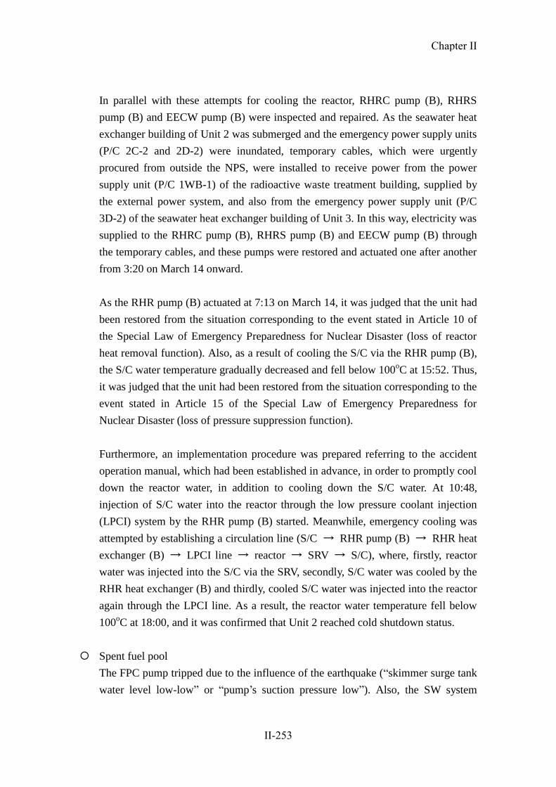
In parallel with these attempts for cooling the reactor, RHRC pump (B), RHRS
pump (B) and EECW pump (B) were inspected and repaired. As the seawater heat
exchanger building of Unit 2 was submerged and the emergency power supply units
(P/C 2C-2 and 2D-2) were inundated, temporary cables, which were urgently
procured from outside the NPS, were installed to receive power from the power
supply unit (P/C 1WB-1) of the radioactive waste treatment building, supplied by
the external power system, and also from the emergency power supply unit (P/C
3D-2) of the seawater heat exchanger building of Unit 3. In this way, electricity was
supplied to the RHRC pump (B), RHRS pump (B) and EECW pump (B) through
the temporary cables, and these pumps were restored and actuated one after another
from 3:20 on March 14 onward.
As the RHR pump (B) actuated at 7:13 on March 14, it was judged that the unit had
been restored from the situation corresponding to the event stated in Article 10 of
the Special Law of Emergency Preparedness for Nuclear Disaster (loss of reactor
heat removal function). Also, as a result of cooling the S/C via the RHR pump (B),
the S/C water temperature gradually decreased and fell below 100oC at 15:52. Thus,
it was judged that the unit had been restored from the situation corresponding to the
event stated in Article 15 of the Special Law of Emergency Preparedness for
Nuclear Disaster (loss of pressure suppression function).
Furthermore, an implementation procedure was prepared referring to the accident
operation manual, which had been established in advance, in order to promptly cool
down the reactor water, in addition to cooling down the S/C water. At 10:48,
injection of S/C water into the reactor through the low pressure coolant injection
(LPCI) system by the RHR pump (B) started. Meanwhile, emergency cooling was
attempted by establishing a circulation line (S/C → RHR pump (B) → RHR heat
exchanger (B) → LPCI line → reactor → SRV → S/C), where, firstly, reactor
water was injected into the S/C via the SRV, secondly, S/C water was cooled by the
RHR heat exchanger (B) and thirdly, cooled S/C water was injected into the reactor
again through the LPCI line. As a result, the reactor water temperature fell below
100oC at 18:00, and it was confirmed that Unit 2 reached cold shutdown status.
Spent fuel pool
The FPC pump tripped due to the influence of the earthquake (“skimmer surge tank
water level low-low” or “pump’s suction pressure low”). Also, the SW system
Chapter II
II-253

pumps (A, B and C) of the non-safety service water system were inundated, and the
RCW pumps (A, B and C) on the first basement in the seawater heat exchanger
building were submerged. As these pumps became inoperable and unable to provide
cooling water into the FPC heat exchanger, cooling of the SFP by FPC could no
longer be achieved.
As a result, the SFP temperature rose to 56oC at its peak. Cooling of the SFP by
RHR pump (B) started at 1:28 on March 16, and finally the SFP temperature
returned at 10:30 on the same day to about 32.5oC, which was the level before the
occurrence of the earthquake.
Containment function
The PCIS and SGTS properly functioned in response to the “reactor water level low
(L-3)” signal, generated at the time when the reactor was scrammed by the “seismic
acceleration high” trip signal at 14:48 on March 11, and the PCV was isolated and
atmospheric pressure inside the reactor building was maintained. Although the PCV
pressure reached as high as about 279kPa gage (on the S/C side) at its peak, it did
not reach the maximum operating pressure of 310kPa gage.
Based on the fact that the PCV pressure was on an upward trend, and assuming that
it would take time to restore the reactor heat removal function, the line
configuration for the PCV pressure resistance ventilation system (the status
whereby the action to open the outlet valve on the S/C side remained available) was
set up.
On-site power supply system
Immediately after the reactor scram, all on-site power supply systems were
operable. However, due to the subsequent tsunamis, the emergency power supply
system (P/C 2C-2 and 2D-2) became inoperable because of the submergence of the
seawater heat exchanger building.
Emergency DGs (A and B systems and the HPCS system) were all operable
immediately after the reactor scram. However, after the tsunami strike, all the
emergency DGs became inoperable, as the RHRS pumps (A, B, C and D), EECW
pumps (A and B) and HPCSC pump failed to be actuated.
Chapter II
II-254

In the course of the subsequent restoration, the load supplied to the inoperable
emergency power supply (P/C 2D-2), RHRC pump (B) and RHRS pump (B),
required for cooling down the reactor and SFP, secured the power supply through
temporary cables installed from the power supply system of the radioactive waste
treatment building (P/C 1WB-1), and the EECW pump (B) secured the power
supply from the emergency power unit (P/C 3D-2) of the heat exchanger building
of Unit 3 (restoration work was conducted on March 14).
As the emergency DG (B) became operable, the emergency power supply unit
(M/C 2D) could receive power from the emergency DG (B) even in the case of a
loss of external power supply.
The main time-series data is shown in Table II-2-42. Statuses of ECCS components,
etc. are shown in Table II-2-43. A schematic view of the plant status is shown in
Figures II-2-112 and 113. The status of the single-line diagram is shown in Figure
II-2-114. Changes in major parameters are shown in Figures II-2-115 and 116.
Chapter II
II-255
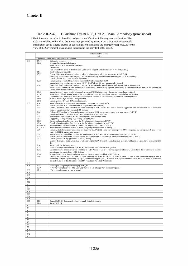
Table II-2-42 Fukushima Dai-ni NPS, Unit 2 – Main Chronology (provisional)
* The information included in the table is subject to modifications following later verifications. The
table was established based on the information provided by TEPCO, but it may include unreliable
information due to tangled process of collectinginformation amid the emergency response. As for the
view of the Government of Japan, it is expressed in the body text of the report.
Fukushima Dai-ni NPS
Unit 2
Operational Status before Earthquake: In operation
3/11 14:46 Earthquake ocuurred
14:48 All control rods were fully inserted
Reactor scram (large earthquake accelation)
Turbine trip
Shut down of one circuit of Tomioka Line ( Line 2 was stopped, Continued receipt of power by Line 1)
15:01 Confirmed reactor subcriticl
15:22 Observed first wave of tsunami (Subsequently several waves were observed intermittently until 17:14)
Emergency diesel generator (Emergency DG) (H) automatically started / immediately stopped due to tsunami impact
Manually closed main steam isolation valve (MSIV)
15:35 Manually started residual heat removal system (RHR) (B) (stopped on 15:38)
Manually stopped circulating water pump (CWP) (C), CWP (A) (B) were automatically stopped
15:41 Emergency diesel generator (Emergency DG) (A) (B) automatically started / immediately stopped due to tsunami impact
Started reactor depressurization (Safety relief valve (SRV) automatically opened) (Subsequently controlled reactor pressure by opening and
closing manually or automatically )
15:43 Manually started reactor core isolation cooling system (RCIC) (Subsequently Started and stopped appropriately)
15:50 Iwado line completely stopped (Line 2 was stopped while line 1 had been down for maintenance before earthquake)
18:33 Determined that a notification event according to NEPA Article 10 ( loss of residual heat removal function) occurred
18:50 Alarm “Dry well high pressure ” was generated
20:02 Manually started dry well (D/W) cooling system
3/12 4:50 Strated alternative injection using makeup water condensate system (MUWC)
4:53 Manually stopped RCIC (Shutdown due to the pressure drop of reactor)
5:32 Licensee determined that a notification event according to NEPA Article 15 ( loss of pressure suppresion function) occurred due to suppersion
chamber water temperature exceeded 100 Cerisius
6:30 Performed S/C cooling by flammability gas control system (FCS) using makeup water pure water system (MUWP)
7:11 Performed D/W spray by using MUWC (Subsequently done appropriately)
7:35 Performed S/C spray by using MUWC (Subsequently done appropriately)
7:52 Stopped S/C cooling by using FCS cooling water (MUWP)
10:33 Started configuration of pressure vent line for primary containment vessel (PCV)
10:58 Completed configuration of pressure vent line for primary containment vessel (PCV)
Around13:38 Received electricity of one circuit of Iwado line (completed restoration of line 2)
Around5:15 Received electricity of two circuits of Iwado line (completed restoration of line 1)
3:20 Manually started emergency equipment cooling water (EECW) (B) (Temporary cabling from 480V emergency low voltage switch gear (power
center (P/C) 3D-2 for receiving power)
3:51 Manually started residual heat removal sea water system (RHRS) pump (B) ( Temporary cabling from P/C 1WB-1)
5:52 Manually started residual heat removal cooling water system (RHRC pump (B) ( Temporary cabling from P/C 1WB-1)
7:13 Manually started RHR (B) (started S/C cooling mode)
Licensee determined that a notification event according to NEPA Article 10 ( loss of residual heat removal function) was restored by starting RHR
(B)
7:50 Started RHR (B) S/C spray mode
10:48 Started water injection to reactor by RHR (B) low pressure core injection (LPCI) mode
15:52 Determined that a notification event according to NEPA Article 15 ( loss of pressure suppresion function) was restored due to suppersion chamber
water temperaturedroped below 100 Cerisius
18:00 Achieved reactor cold shut down by reactor water temperature dropped below 100 Cerisius
22:07 Licensee determined that a notification event according to NEPA Article 10 (increase of radiation dose at site boundary) occurred due to
monitoring post (No.1 ) exceeding 5 μ Gy/h (also monitoring post (No.3) at 0:12 on Mar.15) (assumed that it was due to the effect of radioactive
materials released to the atmosphere caused by Fukushima Dai-ichi NPS accident)
3/15
3/16 1:28 Started spent fuel pool (SFP) cooling by RHR (B)
10:30 SFP water reached at around 32.5 Cerisius (returned to water temperature before earthquake)
3/17 17:19 PCV vent ready status returned to normal
3/18
3/19
3/20
3/21
3/22
3/23
3/24
3/25
3/26
3/27
3/28
3/29
3/30 10:34 Stopped RHR (B) (For provisional power supply installation work)
14:04 Started RHR (B)
3/31
4/1
4/2
4/3
4/4
4/5
4/6
4/7
4/8
4/9
4/10
4/11
4/12
4/13
Chapter II
II-256
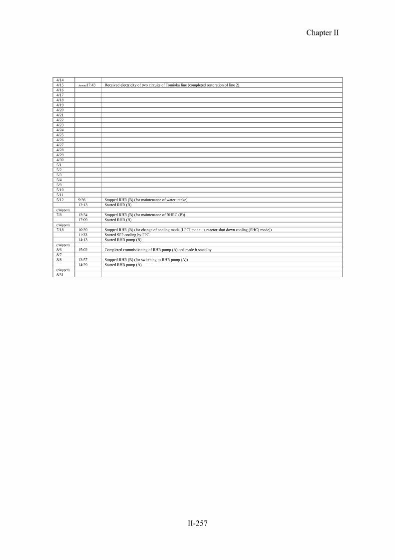
4/14
4/15 Around17:43 Received electricity of two circuits of Tomioka line (completed restoration of line 2)
4/16
4/17
4/18
4/19
4/20
4/21
4/22
4/23
4/24
4/25
4/26
4/27
4/28
4/29
4/30
5/1
5/2
5/3
5/4
5/9
5/10
5/11
5/12 9:36 Stopped RHR (B) (for maintenance of water intake)
12:13 Started RHR (B)
(Skipped)
7/8 13:34 Stopped RHR (B) (for maintenance of RHRC (B))
17:09 Started RHR (B)
(Skipped)
7/18 10:39 Stopped RHR (B) (for change of cooling mode (LPCI mode → reactor shut down cooling (SHC) mode))
11:33 Started SFP cooling by FPC
14:13 Started RHR pump (B)
(Skipped)
8/6 15:02 Completed commissioning of RHR pump (A) and made it stand by
8/7
8/8 13:57 Stopped RHR (B) (for switching to RHR pump (A))
14:29 Started RHR pump (A)
(Skipped)
8/31
Chapter II
II-257

Table II-2-43 Status of Emergency Core Cooling System Equipment etc.[2F-2]
Installed
place
Seismic
class
When the
reactor
scrammed
Till just before
tsunami arrived
after rector scram
Till cold
shutdown
after
tsunami
arrival
Remarks
Cooling
Function
ECCS etc.
RHR(A) R/B 2nd
basement (o.p.0000)
A ○ ○ × Unavailable because RHRS, RHRC and EECW became unoperable due to tsunami. No damage on the pump body
LPCS R/B 2nd
basement (o.p.0000)
A ○ ○ × Unavailable because RHRS, RHRC and EECW became unoperable due to tsunami. No damage on the pump body
RHRC(A) Hx/B 2nd
floor (o.p.11200)
A ○ ○ ×
Unavailable because power supply equipment and motor was submerged and unopearble due to tsunami. No damage on the pump body
RHRC(C) Hx/B 2nd
floor (o.p.11200)
A ○ ○ ×
Unavailable because power supply equipment and motor was submerged and unopearble due to tsunami. No damage on the pump body
RHRS(A) Hx/B 1st
floor (o.p.4200)
A ○ ○ × Unavailable because power supply equipment and motor was submerged and unoperable due to tsunami
RHRS(C) Hx/B 1st
floor (o.p.4200)
A ○ ○ × Unavailable because power supply equipment and motor was submerged and unoperable due to tsunami
EECW(A) Hx/B 1st
floor (o.p.4200)
A ○ ◎ × Unavailable because power supply equipment and motor was submerged and unoperable due to tsunami
RHR(B) R/B 2nd
basement (o.p.0000)
A ○ ◎ ×→◎
Unavailable because RHRS, RHRC and EECW became unoperable due to tsunami. No damage on the pump body. Started operation after recovery of RHRS, RHRC and EECW on Mar. 14
RHR(C) R/B 2nd
basement (o.p.0000)
A ○ ○ ×→○
Unavailable because RHRS, RHRC and EECW became unoperable due to tsunami. No damage on the pump body. Became standby after recovery of RHRS, RHRC and EECW on Mar. 14
RHRC(B) Hx/B 2nd
floor (o.p.11200)
A ○ ◎ ×→◎
Unavailable because power supply equipment and motor was submerged and unoperable due to tsunami. No damage on the pump body. Temporary cabling from RW/B and started operation on Mar. 13
RHRC(D) Hx/B 2nd
floor (o.p.11200)
A ○ ◎ ×
Unavailable because power supply equipment was submerged and unoperable due to tsunami. No damage on the pump body.
RHRS(B) Hx/B 1st
floor (o.p.4200)
A ○ ◎ ×→◎
Unavailable because power supply equipment was submerged and unoperable due to tsunami. No damage on the pump body. Temporary cabling from RW/B and started operation on Mar. 13
RHRS(D) Hx/B 1st
floor (o.p.4200)
A ○ ◎ × Unavailable because power supply equipment and motro was submerged and unoperable due to tsunami.
EECW(B) Hx/B 2nd
floor (o.p.11200)
A ○ ◎ ×→◎
Unavailable because power supply equipment was submerged and unoperable due to tsunami. No damage on the pump body. Temporary cabling from Hx/B of Unit 3 and started operation on Mar. 14
HPCS R/B 2nd
basement (o.p.0000)
A ○ ○ × Unavailable because HPCSC was submerged and unoperable due to tsunami. No damage on the pump body
HPCSC Hx/B 1st
floor (o.p.4200)
A ○ ◎ × Unavailable because motor was submerged and unoperable due to tsunami.
HPCSS Hx/B 1st
floor (o.p.4200)
A ○ ◎ ○
Water
Injection
to
Reactor
RCIC R/B 2nd
basement (o.p.0000)
A ○ ◎ ◎→○ Started operation after tsunami and stopped due to reactor pressure drop on Mar. 12.
MUWC
(Alternative
Injection)
T/B 1st basement (o.p.2400)
B ○ ○ ○→◎→○
Operated on Mar. 12 and became standby on Mar. 14.
Pool
Cooling
SFP Cooling
(FPC)
R/B 4th floor (o.p.31800) B ◎ × ×
Unavailable because of trip by earthequake and RCW out of operation due to tsunami. Started operation on Mar. 16.
SFP Cooling
(RHR)
R/B 2nd basement (o.p.0000)
A ○ ○ ×→◎
Unavailable because RHRS, RHRC and EECW was unoperable due to tsunami. Started operation after recovery of RHRS, RHRC and EECW on Mar. 16 (FPC Auxiliary Coolig Mode).
Confine-
ment
Function
Cantain-
ment
Facility
Reactor
Building A ○ ○ ○
Maintain negative pressure and observed no sign of damage.
Primary
Containment
Vessel
As ○ ○ ○
Observe no sign of damage regarding PCV presuure
(Legend) ◎:in operation ○:stand by ×:Loss of Function or Outage
Chapter II
II-258

Figure II-2-112 Schematic Diagram of Station Status [2F-2] (Part 1)
海
海
※2※1
※2
※1
A
C
B
D
C
A
D
B
ポンプ(A系)の電源系
ポンプ(B系)の電源系
2号機-(1)3月11日地震発生~津波到達前まで
タービン
※3
※3
使用済燃料
プールへ
※4
※4
※5
※5:SFPより
【他非常用炉心冷却系状態】・HPCS ○
・LPCS ○
・RCIC ○原子炉格納容器
熱交換器
熱交換器
熱交換器
熱交換器
熱交換器
熱交換器
熱交換器
○:使用中
○:待機中
×:使用不能
外部電源
常用電源系
海
海
※2※1
※2
※1
A
C
B
D
C
A
D
B
ポンプ(A系)の電源系
ポンプ(B系)の電源系
2号機-(2)3月11日津波到達後
タービン※4
※4
※5
※5:SFPより
【他非常用炉心冷却系状態】・HPCS ×
・LPCS ×
原子炉格納容器
××
×
×
×
×
×
×
×
×
×
×
×
××
×
減圧
熱交換器
熱交換器
熱交換器
熱交換器
熱交換器
熱交換器
熱交換器
○:使用中
○:待機中
×:使用不能
外部電源
常用電源系
原子炉圧力容器
MUWC
MUWC
MSIV
圧力抑制室
RHR
熱交換器(A)
RHR
ポンプ(A)RHR
ポンプ(C)
RHR
ポンプ(B)
RHR
熱交換器(B)
EECWポンプA
RHRCポンプ(A)系
RHRSポンプ(A)系
HPCSCポンプ HPCSSポンプ
RHRSポンプ(B)系EECWポンプB
RHRCポンプ(B)系
RCIC
原子炉圧力容器
圧力抑制室
RHR
熱交換器(A)
RHR
ポンプ(A)RHR
ポンプ(C)
RHR
ポンプ(B)
RHR
熱交換器(B)
MSIV
MUWC
MUWC
EECWポンプA
RHRCポンプ(A)系
RHRSポンプ(A)系
HPCSCポンプ HPCSSポンプ
EECWポンプBRHRSポンプ(B)系
RHRCポンプ(B)系
FCS冷却水
(MUWP)
FCS冷却水
(MUWP)
D/G(A)設備冷却
RHR,LPCS機器冷却
RHR,LPCS機器冷却
D/G(HPCS)設備冷却
HPCS機器冷却
D/G(B)設備冷却
RHR機器冷却
RHR機器冷却
非常用電源系
D/G(A) D/G(B)D/G(HPCS)M/C 2C M/C 2D M/C 2HPCS
使用済燃料
プールへ
SRV
D/G(A)設備冷却
RHR,LPCS機器冷却
RHR,LPCS機器冷却
D/G(HPCS)設備冷却
HPCS機器冷却
D/G(B)設備冷却
RHR機器冷却
RHR機器冷却
SRV
非常用電源系
D/G(A) D/G(B) D/G(HPCS)M/C 2C M/C 2D M/C 2HPCS
× × ×
海水熱交換器建屋
海水熱交換器建屋
【Status of other emergency core cooling systems 】
Primary Containment Vessel
RPV
FCS cooling water
To Turbine
To Spent Fuel Pool
SuppressionPool
In Operation
Stand-by
Disabled
From SFP
RHR pump (C)
RHR pump (B)RHR pump (A)
RHR Heat exchanger (A)
RHR Heat exchanger (B)
Cooling D/G (A) facilitiesCooling RHR, LPCS equipment
Cooling D/G (B) facilitiesCooling RHR equipment
Cooling D/G HPCS) facilities, CoolingHPCS equipment
Cooling RHR, LPCS equipment
Cooling RHRequipment
Seawater heat exchanger building
Power supply system
for Pump A systems
Heat
exchanger
Heat
exchanger
Heat
exchanger
Heat
exchanger
EECW pump A
RHRC pump A system
RHRS pump A system
HPCSC pump HPCSS pump
Sea
Sea
RHRS pump B systemEECW pump B
RHRC pump B system
Heat
exchanger
Heat
exchanger
Heat
exchanger
Power supply system
for Pump B systems
ExternalPower
NormalPower Supply
EmergencyPower Supply
【Status of other emergency core cooling systems 】
RPV
Primary Containment Vessel
To Turbine
To Spent Fuel Pool
Depressurization
FCS cooling water
SuppressionPool
NormalPower Supply Emergency
Power Supply
Disabled
Stand-by
In Operation
RHR Heat exchanger (A)
RHR pump (A)
RHR pump (C)
RHR pump (B)
RHR Heat exchanger (B)
From SFP
ExternalPower
Cooling D/G (A) facilitiesCooling RHR, LPCS equipment
Cooling RHR, LPCS equipment
Cooling D/G HPCS) facilities, CoolingHPCS equipment
Cooling D/G (B) facilitiesCooling RHR equipment
Seawater heat exchanger building
Power supply system
for Pump A systems
Heat
exchanger
Heat
exchanger
Heat
exchanger
Heat
exchanger
RHRS pump A system
Sea
HPCSC pump
RHRC pump A systemEECW pump A
HPCSS pump
EECW pump BRHRS pump B system
Heat
exchanger
Heat
exchanger
Heat
exchanger
Power supply system
for Pump B systems
RHRC pump B system
Sea
Cooling RHRequipment
Unit 2-(1)March 11After earthquake until just before tsunami reached
Unit 2-(2)March 11After tsunami reached
Chapter II
II-259

Figure II-2-113 Schematic Diagram of Station Status [2F-2] (Part 2)
海
海
※2※1
A
C
B
D
C
A
D
B
ポンプ(A系)の電源系
ポンプ(B系)の電源系
2号機-(3)3月14日RHRSポンプ,RHRCポンプ復旧
RHRポンプ(B)起動(S/P冷却)
タービン
※3
※3
使用済燃料
プールへ
※4
※5
※5:SFPより
【他非常用炉心冷却系状態】・HPCS ×
・LPCS ×
・RCIC × 原子炉格納容器
仮設電源
(P/C3D-2使用)
仮設電源
(P/C1WB-1使用)
×
××
×
×
×
×
×
× ××※4
仮設電源
(P/C1WB-1使用)
熱交換器
熱交換器
熱交換器
熱交換器
熱交換器
熱交換器
熱交換器
○:使用中
○:待機中
×:使用不能
外部電源
常用電源系
海
海
※2※1
A
C
B
D
C
A
D
B
ポンプ(A系)の電源系
ポンプ(B系)の電源系
2号機-(4)3月14日 18:00
冷温停止時
タービン
※3
※3
使用済燃料
プールへ
※4
※5
※5:SFPより
【他非常用炉心冷却系状態】・HPCS ×
・LPCS ×
・RCIC × 原子炉格納容器
仮設電源
(P/C3D-2使用)
仮設電源
(P/C1WB-1使用)
×
××
×
×
×
×
×※4
仮設電源
(P/C1WB-1使用)
熱交換器
熱交換器
熱交換器
熱交換器
熱交換器
熱交換器
熱交換器
○:使用中
○:待機中
×:使用不能
外部電源
常用電源系
×
原子炉圧力容器
MSIV
MUWC
MUWC
圧力抑制室
RHR
熱交換器(A)
RHR
ポンプ(A)
RHR
ポンプ(C)
RHR
ポンプ(B)
RHR
熱交換器(B)
RHRSポンプ(A)系
RHRCポンプ(A)系
EECWポンプA
HPCSCポンプHPCSSポンプ
RHRSポンプ(B)系
EECWポンプB
RHRCポンプ(B)系
MSIV原子炉圧力容器
圧力抑制室
MUWC
MUWC
RHR
熱交換器(A)
RHR
ポンプ(A)
RHR
ポンプ(C)
RHR
ポンプ(B)
RHR
熱交換器(B)
RHRSポンプ(A)系
RHRCポンプ(A)系
EECWポンプA
HPCSCポンプ HPCSSポンプ
RHRSポンプ(B)系
EECWポンプB
RHRCポンプ(B)系
FCS冷却水
(MUWP)
FCS冷却水
(MUWP)
※2
※1
D/G(A)設備冷却
RHR,LPCS機器冷却
RHR,LPCS機器冷却
RHR機器冷却
非常用電源系
D/G(A) D/G(B) D/G(HPCS)M/C 2C M/C 2D M/C 2HPCS× ×
SRV
海水熱交換器建屋
海水熱交換器建屋
※2
※1
RHR,LPCS機器冷却
RHR機器冷却
SRV
非常用電源系
D/G(A) D/G(B) D/G(HPCS)M/C 2C M/C 2D M/C 2HPCS
×
×
D/G(B)設備冷却
RHR機器冷却
D/G(HPCS)設備冷却
HPCS機器冷却
D/G(HPCS)設備冷却
HPCS機器冷却
D/G(B)設備冷却
RHR機器冷却
D/G(A)設備冷却
RHR,LPCS機器冷却
Primary Containment Vessel
RPV
To Spent Fuel Pool
FCS cooling water
RHR pump (A)
RHR Heat exchanger (A)
RHR pump (C)
From SFP
RHR pump (B)
RHR Heat exchanger (B)
Stand-by
Disabled
NormalPower Supply
In Operation
EmergencyPower Supply
Cooling RHRequipment
Cooling D/G (B) facilitiesCooling RHR equipment
Cooling D/G HPCS) facilities, CoolingHPCS equipment
Cooling RHR, LPCS equipment
Cooling D/G (A) facilitiesCooling RHR, LPCS equipment
Seawater heat exchanger building
Power supply system
for Pump A systems
Heat
exchanger
EECW pump A
RHRC pump A system
RHRS pump A system
Heat
exchanger
Heat
exchanger
Heat
exchanger
Heat
exchanger
Heat
exchanger
Heat
exchanger
HPCSC pump
EECW pump B
RHRC pump B system
Power supply system
for Pump B systems
Sea
Sea
ExternalPower
【Status of other emergency core cooling systems 】
SuppressionPool
HPCSS pump
Primary Containment Vessel
RPV To Turbine
To Spent Fuel Pool
FCS cooling water
SuppressionPool
Disabled
Stand-by
In Operation
NormalPower Supply
EmergencyPower Supply
RHR Heat exchanger (A)
RHR pump (A)
From SFP
RHR pump (C)
RHR pump (B)
RHR Heat exchanger (B)
Seawater heat exchanger building
Power supply system
for Pump A systems
EECW pump A
RHRC pump A system
Heat
exchanger
Heat
exchanger
Heat
exchanger
RHRS pump A system
Heat
exchanger
Cooling D/G (A) facilitiesCooling RHR, LPCS equipment
Cooling RHR, LPCS equipment
Cooling D/G HPCS) facilities, CoolingHPCS equipment
Cooling RHRequipment
Cooling D/G (B) facilitiesCooling RHR equipment
Temporary power supply
(Using P/C 3D-2)
Temporary power supply
(Using P/C 1WB-1)
EECW pump B
RHRC pump B system
Power supply system
for Pump B systems
Heat
exchanger
Heat
exchanger
Heat
exchanger
HPCSC pump HPCSS pump
RHRS pump B system
Sea
Temporary power supply
(Using P/C 1WB-1)
Sea
To Turbine
Temporary power supply
(Using P/C 3D-2)
Temporary power supply
(Using P/C 1WB-1)Temporary power supply
(Using P/C 1WB-1)
RHRS pump B system
【Status of other emergency core cooling systems 】
ExternalPower
Unit 2-(3)March 14, RHRS pump and RHRC pump restoredRHR pump (B) started (S/P cooling)
Unit 2-(4)March 14, 18:00
At cold shutdowm
Chapter II
II-260

Figure II-2-114 Status of Single-line Diagram of Emergency Power Supply System [2F-2]
D/G
HPCSポンプ
HPCSCポンプ
HPCSSポンプ
D/G(HPCS)
6.9kV M/C
2HPCS
※2
MCC
2HPCS
D/G
RHRポンプ(
A)
RHRCポンプ(
A)
RHRCポンプ(
C)
D/G(A)
6.9kV M/C 2C
※4
480kV P/C
2C-1
LPCSポンプ
480kV P/C
2C-2
RHRSポンプ(
A)
RHRSポンプ(
C)
D/G
RHRポンプ(
C)
RHRCポンプ(
B)
RHRCポンプ(
D)
D/G(B)
6.9kV M/C 2D
※6
480kV P/C
2D-1
RHRポンプ(
B)
480kV P/C
2D-2
RHRSポンプ(
B)
RHRSポンプ(
D)
EECWポンプ(
A)
EECWポンプ(
B)
2号機 (3/11 津波到達以降)
D/G
HPCSポンプ
HPCSCポンプ
HPCSSポンプ
D/G(HPCS)
6.9kV M/C
2HPCS
※2
MCC
2HPCS
D/G
RHRポンプ(
A)
RHRCポンプ(
A)
RHRCポンプ(
C)
D/G(A)
6.9kV M/C 2C
※4
480kV P/C
2C-1
LPCSポンプ
480kV P/C
2C-2
RHRSポンプ(
A)
RHRSポンプ(
C)
D/G
RHRポンプ(
C)
RHRCポンプ(
B)
RHRCポンプ(
D)
D/G(B)
6.9kV M/C 2D
※6
480kV P/C
2D-1
RHRポンプ(
B)
480kV P/C
2D-2
RHRSポンプ(
B)
RHRSポンプ(
D)
EECWポンプ(
A)
EECWポンプ(
B)
2号機 (3/14 18:00 冷温停止)
※16P/C
1WB-1
※15P/C
1WB-1
※17P/C
3D-2
※13 ※14 ※15 ※16
6.9kV M/C
1SA-16.9kV M/C
1SA-2
起動変圧器
1SA
電気ボイラー用
66kV開閉所
66kV起動用開閉所
66kV 岩井戸線
1号 2号
高起動
変圧器
2号機 3号機 4号機1号機
G G G G
6.9kV M/C
1SB-16.9kV M/C
1SB-2
起動変圧器
1SB
500kV 富岡線
1号 2号
6.9kV M/C
3SA-16.9kV M/C
3SA-2
起動変圧器
3SA
6.9kV M/C
3SB-1
6.9kV M/C
3SB-2
起動変圧器
3SB
※1 ※2 ※3 ※4 ※5 ※6 ※7 ※8 ※9 ※10 ※11 ※12480V P/C
1WB-1
3/12 13:38
受電
3/13 5:15
受電
被水により使用不能
充電状態
遮断器「投入」状態
遮断器「開放」状態(待機)
仮設ケーブル
運転中の機器赤字
遮断器「開放」状態(故障時)
非常用電源系 単線結線図 (2号機 津波到達時及び冷温停止時の状態)Single-line Diagram of Emergency Power Supply System (Unit 2, Status When Tsunami Reached and Cold Shutdown)
Line 1 Line 2
Unit 1 Unit 2 Unit 3 Unit 4
High startup transformer
66kV substation for electric boilers
March 13, 5:15Received electricity
66kV substation for startup
Unit 2 March 12, 13:38
Received electricity
Unit 1 Breaker “Close” status
Breaker “Open” status (standby)
Breaker “Open” status (failed)
Energized
Temporary cabling
In red – Equipment in Operation
Unavailable due to submerging
Startup transformer
Startup transformer
Startup transformer Startup transformer
66kV Iwaido line500kV Tomioka Line
Unit 2 (March 11 After tsunami reached)
Unit 2 (March 14 18:00 Cold shutdown)
HPCS
P HPCSC
P
HPCSS
P
LPCS
P
RHR
P
(A) E E CW
P
(A)
R H R C
P
(A)
R H R C
P
(C)
R H R S
P
(A)
R H R S
P
(C)
R H R
P
(B)
R H R
P
(C) E E C W
P
(B)
R H R C
P
(B)
R H R C
P
(D)
R H R S
P
(B)
R H R S
P
(D)
HPCS
P HPCSC
P
HPCSS
P
LPCS
P
RHR
P
(A) E E CW
P
(A)
R H R C
P
(A)
R H R C
P
(C)
R H R S
P
(A)
R H R S
P
(C)
R H R
P
(B)
R H R
P
(C) E E C W
P
(B)
R H R C
P
(B)
R H R C
P
(D)
R H R S
P
(B)
R H R S
P
(D)
D/G
HPCSポンプ
HPCSCポンプ
HPCSSポンプ
D/G(HPCS)
6.9kV M/C
2HPCS
※2
MCC
2HPCS
D/G
RHRポンプ(
A)
RHRCポンプ(
A)
RHRCポンプ(
C)
D/G(A)
6.9kV M/C 2C
※4
480kV P/C
2C-1
LPCSポンプ
480kV P/C
2C-2
RHRSポンプ(
A)
RHRSポンプ(
C)
D/G
RHRポンプ(
C)
RHRCポンプ(
B)
RHRCポンプ(
D)
D/G(B)
6.9kV M/C 2D
※6
480kV P/C
2D-1
RHRポンプ(
B)
480kV P/C
2D-2
RHRSポンプ(
B)
RHRSポンプ(
D)
EECWポンプ(
A)
EECWポンプ(
B)
2号機 (3/11 津波到達以降)
D/G
HPCSポンプ
HPCSCポンプ
HPCSSポンプ
D/G(HPCS)
6.9kV M/C
2HPCS
※2
MCC
2HPCS
D/G
RHRポンプ(
A)
RHRCポンプ(
A)
RHRCポンプ(
C)
D/G(A)
6.9kV M/C 2C
※4
480kV P/C
2C-1
LPCSポンプ
480kV P/C
2C-2
RHRSポンプ(
A)
RHRSポンプ(
C)
D/G
RHRポンプ(
C)
RHRCポンプ(
B)
RHRCポンプ(
D)
D/G(B)
6.9kV M/C 2D
※6
480kV P/C
2D-1
RHRポンプ(
B)
480kV P/C
2D-2
RHRSポンプ(
B)
RHRSポンプ(
D)
EECWポンプ(
A)
EECWポンプ(
B)
2号機 (3/14 18:00 冷温停止)
※16P/C
1WB-1
※15P/C
1WB-1
※17P/C
3D-2
※13 ※14 ※15 ※16
6.9kV M/C
1SA-16.9kV M/C
1SA-2
起動変圧器
1SA
電気ボイラー用
66kV開閉所
66kV起動用開閉所
66kV 岩井戸線
1号 2号
高起動
変圧器
2号機 3号機 4号機1号機
G G G G
6.9kV M/C
1SB-16.9kV M/C
1SB-2
起動変圧器
1SB
500kV 富岡線
1号 2号
6.9kV M/C
3SA-16.9kV M/C
3SA-2
起動変圧器
3SA
6.9kV M/C
3SB-1
6.9kV M/C
3SB-2
起動変圧器
3SB
※1 ※2 ※3 ※4 ※5 ※6 ※7 ※8 ※9 ※10 ※11 ※12480V P/C
1WB-1
3/12 13:38
受電
3/13 5:15
受電
被水により使用不能
充電状態
遮断器「投入」状態
遮断器「開放」状態(待機)
仮設ケーブル
運転中の機器赤字
遮断器「開放」状態(故障時)
非常用電源系 単線結線図 (2号機 津波到達時及び冷温停止時の状態)Single-line Diagram of Emergency Power Supply System (Unit 2, Status When Tsunami Reached and Cold Shutdown)
Line 1 Line 2
Unit 1 Unit 2 Unit 3 Unit 4
High startup transformer
66kV substation for electric boilers
March 13, 5:15Received electricity
66kV substation for startup
Unit 2 March 12, 13:38
Received electricity
Unit 1 Breaker “Close” status
Breaker “Open” status (standby)
Breaker “Open” status (failed)
Energized
Temporary cabling
In red – Equipment in Operation
Unavailable due to submerging
Startup transformer
Startup transformer
Startup transformer Startup transformer
66kV Iwaido line500kV Tomioka Line
Unit 2 (March 11 After tsunami reached)Unit 2 (March 11 After tsunami reached)
Unit 2 (March 14 18:00 Cold shutdown)Unit 2 (March 14 18:00 Cold shutdown)
HPCS
P HPCSC
P
HPCSS
P
LPCS
P
RHR
P
(A) E E CW
P
(A)
R H R C
P
(A)
R H R C
P
(C)
R H R S
P
(A)
R H R S
P
(C)
R H R
P
(B)
R H R
P
(C) E E C W
P
(B)
R H R C
P
(B)
R H R C
P
(D)
R H R S
P
(B)
R H R S
P
(D)
HPCS
P HPCSC
P
HPCSS
P
LPCS
P
RHR
P
(A) E E CW
P
(A)
R H R C
P
(A)
R H R C
P
(C)
R H R S
P
(A)
R H R S
P
(C)
R H R
P
(B)
R H R
P
(C)
HPCS
P HPCSC
P
HPCSS
P
LPCS
P
RHR
P
(A) E E CW
P
(A)
R H R C
P
(A)
R H R C
P
(C)
R H R S
P
(A)
R H R S
P
(C)
R H R
P
(B)
R H R
P
(C) E E C W
P
(B)
R H R C
P
(B)
R H R C
P
(D)
R H R S
P
(B)
R H R S
P
(D)
Chapter II
II-261

-1000
-500
0
500
1000
1500
3/11 3/12 3/13 3/14 3/15 3/16 3/17 3/18 3/19
原子炉水位(広帯域)(mm)
(mm)
オーバースケール
Fig. II-2-115 Variation of major parameters [2F-2] (from March 11 to 19) (1)
Beyond scale
Reactor level (wide range) (mm)
Reactor pressure (MPa[gage])
Chapter II
II-262

0
10
20
30
40
50
60
70
3/11 3/12 3/13 3/14 3/15 3/16 3/17 3/18 3/19
燃料プール表面温度(℃)
FPCポンプ入口温度(℃)
(℃)
FPCポンプ停止
温度計測不良
Fig. II-2-116 Variation of major parameters [2F-2] (from March 11 to 19) (2)
S/C pressure (kPa[gage])
S/C water temperature (oC)
Fuel pool surface temperature (oC)
FPC pump inlet temperature (oC)
Temperature measurrment unavailable
FPC pump stopped
Chapter II
II-263

c Fukushima Dai-ni NPS Unit 3
Overall conditions immediately after the occurrence of the earthquake
The reactor, which had been under operation at its rated thermal power, was
scrammed automatically at 14:48 on March 11, immediately after the occurrence of
the earthquake, due to excessive seismic acceleration. All the control rods were
fully inserted and the reactor was scrammed properly. It was confirmed at 15:05 on
March 11 that the reactor became subcritical.
Immediately after the reactor scram, voids in the reactor core decreased and the
reactor water level declined to as low as the “reactor water level low (L-3).” After
that, the reactor water level was recovered by water supplied from the reactor feed
water system without further declining to the level at which the ECCS pump and
RCIC automatically actuate.
At 15:37 on March 11, the MSIV was fully closed manually so that the reactor
pressure could be controlled by the SRV in preparation for the situations that the
CWP stopped due to the influence of the tsunamis and the resulting inability to
condensate main steam by the condenser, and also that the turbine gland seal steam
was lost caused by the shutdown of the auxiliary boilers due to the influence of the
earthquake.
In association with the complete closure of the MSIV, the RCIC was manually
actuated at 16:06, and water injection into the reactor was started.
Influence of the tsunamis
Mainly because the seawater heat exchanger building was submerged by the
tsunamis, it was judged that RHRC pumps (A and C), RHRS pumps (A and C), and
EECW pump (A) failed to be actuated (later, it was confirmed at the site that some
motors and emergency power supply systems (P/C 3C-2) became inoperable
because they had been inundated).
It is estimated that the emergency power supply unit (P/C 3D-2) and its load RHRC
pumps (B and D), RHRS pumps (B and D) and EECW pump (B) and also the
HPCSC pump and HPCSS pump were operable as the extent of submersion of the
seawater heat exchanger building by the tsunamis was small in comparison to the
Chapter II
II-264

cases of other units, and the effect of inundation of the equipment was also small.
Furthermore, RHR pumps (B and C) and the HPCS pump were also operable as the
second basement of the reactor compartment of reactor building was not submerged
by the tsunamis.
Operations until the establishment of cold shutdown status
Initially, water was supplied to the reactor by the RCIC. However, from 22:53 on
March 11 onwards, an alternate feed water system was started, using the MUWC,
which had been introduced as an AM measure. Later, the RCIC was manually
stopped at 23:11, due to the fall of steam pressure driving the RCIC turbine in
association with depressurization of the reactor. After that, alternate feed water via
the MUWC was conducted. At 9:37 on March 12, water injection and cooling by
the operable RHR pump (B) was started and the reactor water temperature fell
below 100oC at 12:15, and it was confirmed that the unit reached cold shutdown
status.
A “drywell pressure high” (set value: 13.7kPa gage) alarm was issued at 19:46 on
March 11, because the temperature and pressure in the PCV rose due to operation
of the RCIC and SRV. The HPCS pump, LPCS pump, and RHRS pumps (A and C)
did not actuate, as measures to prevent automatic actuation had been taken for these
pumps because the coolant system (RHRC pumps (A and C), RHRS pumps (A and
C) and EECW pump (A)) were inoperable. RHR pump (B) was under operation for
cooling the S/C when the “drywell pressure high” alarm was issued (at 15:36 on
March 11).
Spent fuel pool
The FPC pump tripped due to the influence of the earthquake (“skimmer surge tank
water level low-low” or “pump’s suction pressure low”). Also, the SW system
pumps (A, B and C) of the non-safety service water system were inundated, and the
RCW pumps (A, B and C) on the first basement in the seawater heat exchanger
building were submerged. As these pumps became inoperable and unable to provide
cooling water into the FPC heat exchanger, the cooling of the SFP by FPC could no
longer be achieved.
As a result, the SFP temperature rose to 51oC at its peak. At 17:42 on March 15,
Chapter II
II-265

cooling water for the FPC heat exchanger was switched from RCW to RHRC.
Subsequently, at 22:30 on March 16, the SFP water temperature returned to about
34oC, which was the level before the occurrence of the earthquake.
Containment function
PCIS and SGTS properly functioned in response to the “reactor water level low
(L-3)” signal, generated at the time when the reactor was scrammed by the “seismic
acceleration high” trip signal at 14:48 on March 11, and the PCV was isolated and
atmospheric pressure inside the reactor building was maintained. Although the PCV
pressure reached about 38kPa gage (on the D/W side) at its peak, it did not reach
the maximum operating pressure of 310kPa gage.
Just in case the PCV pressure rises, the line configuration for the PCV pressure
resistance ventilation system (the status whereby the action to open the outlet valve
on the S/C side remained available) was set up.
On-site power supply system
Immediately after the reactor scram, all on-site power supply systems were
operable. However, due to the subsequent tsunamis, the emergency power supply
system (P/C 3C-2) became inoperable because of the submergence of the seawater
heat exchanger building.
Emergency DGs (A and B systems, and HPCS system) were all operable
immediately after the reactor scram. However, after the tsunami strike, the
emergency DG (A) became inoperable, as RHRS pumps (A and C) and EECW
pump (A) failed to be actuated.
The main time-series data is shown in Table II-2-44. Statuses of ECCS components,
etc. are shown in Table II-2-45. A schematic view of the plant status is shown in
Figures II-2-117 and 118. The status of the single-line diagram is shown in Figure
II-2-119. Changes in major parameters are shown in Figures II-2-120 and 121.
Chapter II
II-266

Table II-2-44 Fukushima Dai-ni NPS Unit 3 – Main Chronology (provisional) * The information included in the table is subject to modifications following later verifications. The table was established based on the information provided by TEPCO, but it may include unreliable information due to tangled process of collecting information amid the emergency response. As for the view of the Government of Japan, it is expressed in the body text of the report.
Fukushima Daini Nuclear Power Plant Unit 3
Status before earthquake: In operation
3/11 14:46
14:48
Earthquake occurred
All control rods inserted
Automatic reactor shutdown (Trip caused by high seismic acceleration)
Automatic turbine shutdown
One circuit of Tomioka Line stopped (Line 2 tripped, while Line 1 continued receiving electricity)
Confirmed reactor subcriticality
15:05
15:22 Observed first wave of tsunami (Tsunami was observed intermittently until 17:14)
15:34 Manually stopped circulating water pump (CWP) (C)
15:35 Emergency diesel generator (emergency DG) (A) and (B) started automatically/emergency DG (A) immediately stopped due to the
tsunami attack
15:36 Manually started residual heat removal system (RHR) (B) (S/C cooling mode)
15:37 Manually closed main steam isolation valve (MSIV)
15:38 Manually stopped circulating water pump (CWP) (B)
15:46 Started reactor depressurization (Safety relief valve (SRV) opened automatically) (Subsequently the reactor pressure controlled with
automatic or manual opening/closing)
15:50 Iwaido Line completely stopped (Line 2 stopped, while Line 1 has already been down for maintenance before the earthquake)
16:06 Manually started reactor core isolation cooling system (RCIC) (started or stopped subsequently as appropriate)
16:48 Circulating water pump (CWP) (B) manually stopped
19:46 "High Dry Well Pressure" alarm issued
RHR (B) Automatically switched from S/C cooling mode to low-pressure injection (LPCI) mode
20:07 RHR (B) Switched to LPCI mode S/C cooling mode
20:12 Manually started dry well (D/W) cooling system
22:53 Started alternate injection using condensate water makeup system (MUWC)
23:11 Manually stopped RCIC (Shutdown due to the pressure drop of reactor)
3/12 0:06 Started preparation of configuration of RHR (B) reactor shutdown cooling (SHC) mode
1:23 Manually stopped RHR (B) (For preparation of SHC mode)
2:39 Manually started RHR (B) (S/C cooling mode started)
2:41 Started RHR (B) S/C spray mode
7:59 Manually stopped RHR (B) (To stop S/C cooling mode / S/C spray mode)
9:37 Manually started RHR (B) (To start operation in SHC mode)
12:08 Started configuration of pressure vent line for primary containment vessel (PCV)
12:13 Completed configuration of PCV pressure vent line
12:15 As the reactor water temperature dropped below 100℃, the reactor was put into a state of cold shutdown
around 13:38 One circuit of Iwaido Line received electricity (Line 2 finished recovery)
3/13 around 5:15 Two circuits of Iwaido Line received electricity (Line 1 finished recovery)
3/14 22:07 Determined that a reportable event (increase of radiation dose on the site boundary) had occurred in accordance with Article 10 of the
Nuclear Disaster Special Measures Law because Monitoring Post No.1 measured radiation dose in excess of 5 μGy/h, which was also
measured by Monitoring Post No.3 at 0:12 on March 15. (It is estimated that the increase in dose was caused by the effect of radioactive
materials released into the atmosphere due to the Fukushima Daiichi accident.)
3/15 17:42 Switched heat exchanger cooling water for fuel pool cooling and purification system (FPC) (From reactor auxiliary cooling water system
(RCW) to residual heat removal cooling system (RHRC).)
3/16 22:30 Spent fuel pool (SFP) water temperature measured about 34℃ (Returned to the temperature before the earthquake)
3/17 9:55 The unit returned form PCV vent ready state to normal state
3/18
3/19
3/20 14:36
15:05
Stopped RHR (B) (To switch to S/C cooling)
Started RHR (B) (To start S/C cooling)
3/21
3/22
3/23
3/24
3/25
3/26
3/27
3/28
3/29
3/30
3/31
4/1
4/2
4/3
4/4
4/5
4/6
4/7
4/8
4/9
4/10
4/11
4/12
4/13
4/14
4/15 around 17:43 Two circuits of Tomioka Line received electricity (Line 2 restored)
(Skipped)
5/9 9:51
14:46
Stopped RHR (B) (For intake inspection)
Started RHR (B)
(Skipped)
6/8 around 18:10 Oil film was found around the discharge structure of Units 3 and 4
Measures were taken to collect oil and prevent its spread by installing an oil fence and using oil absorbing sheets.
(Skipped)
8/31
Chapter II
II-267

Table II-2-45 Status of Emergency Core Cooling System Equipment etc.[2F-3]
Installed
place
Seismic
class
When the
reactor
scrammed
Till just before
tsunami arrived
after rector scram
Till cold
shutdown
after
tsunami
arrival
Remarks
Cooling
Function
ECCS etc.
RHR(A) R/B 2nd
basement (o.p.0000)
A ○ ○ × Unavailable because RHRS, RHRC and EECW was unoperable due to tsunami. No damage on the pump body
LPCS R/B 2nd
basement (o.p.0000)
A ○ ○ × Unavailable because RHRS, RHRC and EECW was unoperable due to tsunami. No damage on the pump body
RHRC(A) Hx/B 1st
floor (o.p.4200)
A ○ ◎ × Unavailable because power supply equipment and motor was submerged and unoperable due to tsunami
RHRC(C) Hx/B 1st
floor (o.p.4200)
A ○ ◎ × Unavailable because power supply equipment and motor was submerged and unoperable due to tsunami
RHRS(A) Hx/B 1st
floor (o.p.4200)
A ○ ◎ ×
Unavailable because power supply equipment was submerged and unoperable due to tsunami. No damage on the pump body
RHRS(C) Hx/B 1st
floor (o.p.4200)
A ○ ◎ ×
Unavailable because power supply equipment was submerged and unoperable due to tsunami. No damage on the pump body
EECW(A) Hx/B 1st
floor (o.p.4200)
A ○ ◎ × Unavailable because power supply equipment and motor was submerged and unoperable due to tsunami
RHR(B) R/B 2nd
basement (o.p.0000)
A ○ ◎ ◎ Started operation on Mar. 11 (S/C Cooling mode). Transferred to Shutdown Cooling mode on Mar. 12.
RHR(C) R/B 2nd
basement (o.p.0000)
A ○ ○ ○
RHRC(B) Hx/B 1st
floor (o.p.4200)
A ○ ◎ ◎ Started operation on Mar. 11.
RHRC(D) Hx/B 1st
floor (o.p.4200)
A ○ ◎ ◎ Started operation on Mar. 11.
RHRS(B) Hx/B 1st
floor (o.p.4200)
A ○ ◎ ◎ Started operation on Mar. 11.
RHRS(D) Hx/B 1st
floor (o.p.4200)
A ○ ◎ ◎ Started operation on Mar. 11.
EECW(B) Hx/B 1st
floor (o.p.4200)
A ○ ◎ ◎ Started operation on Mar. 11.
HPCS R/B 2nd
basement (o.p.0000)
A ○ ○ ○
HPCSC Hx/B 1st
floor (o.p.4200)
A ○ ◎ ◎
HPCSS Hx/B 1st
floor (o.p.4200)
A ○ ◎ ◎
Water
Injection
to
Reactor
RCIC R/B 2nd
basement (o.p.0000)
A ○ ◎ ◎→○ Started operation after tsunami and stopped due to reactor pressure drop on Mar. 11.
MUWC
(Alternative
Injection)
T/B 2nd basement
(o.p.-2000) B ○ ○ ○→◎→○
Started operated on Mar. 11 and became stand by on Mar. 12.
Pool
Cooling
SFP Cooling
(FPC)
R/B 4th floor (o.p.31800) B ◎ × ×→◎
Unavailable due to trip by earthequake and RCW out of operation due to tsunami. Started on Mar. 15 (Cooling water for FPC heat exchanger was supplied by RHRC) Switched cooling water to RCW after recovery of RCW on June 13.
SFP Cooling
(RHR)
R/B 2nd basement (o.p.0000)
A ○ ○ ○
Confine-
ment
Function
Cantain-
ment
Facility
Reactor
Building A ○ ○ ○
Maintain negative pressure and observed no sign of damage.
Primary
Containment
Vessel
As ○ ○ ○
Observe no sign of damage regarding PCV presuure
(Legend) ◎:in operation ○:stand by ×:Loss of Function or Outage
Chapter II
II-268

Figure II-2-117 Schematic Diagram of Station Status [2F-3] (Part 1)
海
RHR
ポンプ(A)
圧力抑制室
RHR
熱交換器(A)
RHR
ポンプ(C)
RHR
ポンプ(B)
RHR
熱交換器(B)
海
※2※1
※1
RHRCポンプ(B)系
RHRCポンプ(A)系
EECWポンプ(B)
EECWポンプ(A)
A
C
B
D
RHRSポンプ(A)系
C
A
RHRSポンプ(B)系
D
B
ポンプ(A系)の電源系
ポンプ(B系)の電源系
3号機-(1)3月11日地震発生~津波到達前まで
タービン
※3
※3
使用済燃料
プールへ
HPCSSポンプHPCSCポンプ
※4
※4
※5
※5:SFPより
MUWC
MUWC
原子炉格納容器
熱交換器
熱交換器
熱交換器
熱交換器
熱交換器
熱交換器
熱交換器
○:使用中
○:待機中
×:使用不能
外部電源
常用電源系
海
RHR
ポンプ(A)
圧力抑制室
RHR
熱交換器(A)
RHR
ポンプ(C)
RHR
ポンプ(B)
RHR
熱交換器(B)
海
※2※1RHRCポンプ(B)系
RHRCポンプ(A)系
EECWポンプ(B)
EECWポンプ(A)
A
C
B
D
RHRSポンプ(A)系
C
A
RHRSポンプ(B)系
D
B
ポンプ(A系)の電源系
ポンプ(B系)の電源系
3号機-(2)3月11日津波到達後
タービン
使用済燃料
プールへ
HPCSSポンプHPCSCポンプ
※4
※4
※5
※5:SFPより
MUWC
MUWC
【他非常用炉心冷却系状態】・HPCS ○
・LPCS ×
原子炉格納容器
×
×
×
×
××
減圧
熱交換器
熱交換器
熱交換器
熱交換器
熱交換器
熱交換器
熱交換器
○:使用中
○:待機中
×:使用不能
外部電源
常用電源系
×
【他非常用炉心冷却系状態】
・HPCS ○
・LPCS ○
・RCIC ○
原子炉圧力容器
原子炉圧力容器
MSIV
MSIV
FCS冷却水
(MUWC)
FCS冷却水
(MUWC)
海水熱交換器建屋
※2
D/G(A)設備冷却
RHR,LPCS機器冷却
RHR,LPCS機器冷却
D/G(HPCS)設備冷却
HPCS機器冷却
D/G(B)設備冷却
RHR機器冷却
RHR機器冷却
非常用電源系
D/G(A) D/G(B) D/G(HPCS)M/C 3C M/C 3D M/C 3HPCS
海水熱交換器建屋
※1
※2
D/G(A)設備冷却
RHR,LPCS機器冷却
RHR,LPCS機器冷却
D/G(HPCS)設備冷却
HPCS機器冷却
D/G(B)設備冷却
RHR機器冷却
RHR機器冷却
非常用電源系
D/G(A) D/G(B) D/G(HPCS)M/C 3C M/C 3D M/C 3HPCS
×
SRV
SRV
RCIC
【Status of other emergency core cooling systems 】
Unit 3-(1)March 11After earthquake until just before tsunami reached
Primary Containment Vessel
RPV
To Spent Fuel Pool
To Turbine
FCS cooling water
SuppressionPool
In Operation
Stand-by
Disabled
RHR pump (A)
RHR Heat exchanger (A)
RHR pump (C)
From SFP
RHR pump (B)
RHR Heat exchanger (B)
Cooling D/G (A) facilitiesCooling RHR, LPCS equipment
Cooling RHR, LPCS equipment
Cooling D/G (B) facilitiesCooling RHR equipment
Cooling D/G HPCS) facilities, CoolingHPCS equipment
Cooling RHRequipment
Seawater heat exchanger building
Power supply system
for Pump A systems
EECW pump A
RHRC pump A system
Heat
exchanger
Heat
exchanger
Heat
exchanger
Heat
exchanger
Heat
exchanger
Heat
exchanger
Heat
exchanger
Sea
Sea
RHRS pump A system
HPCSC pump HPCSS pump
RHRS pump B systemEECW pump B
RHRC pump B system
Power supply system
for Pump B systems
EmergencyPower Supply
ExternalPower
NormalPower Supply
【Status of other emergency core cooling systems 】
Unit 3-(2)March 11
After tsunami reached
Primary Containment Vessel
RPV
To Spent Fuel Pool
To Turbine
FCS cooling water
SuppressionPool
In Operation
Stand-by
Disabled
RHR pump (A)
RHR Heat exchanger (A)
RHR pump (C)
From SFP
RHR pump (B)
RHR Heat exchanger (B)
Cooling D/G (A) facilitiesCooling RHR, LPCS equipment
Cooling RHR, LPCS equipment
Cooling D/G (B) facilitiesCooling RHR equipment
Cooling D/G HPCS) facilities, CoolingHPCS equipment
Cooling RHRequipment
Seawater heat exchanger building
Power supply system
for Pump A systems
EECW pump A
RHRC pump A system
Heat
exchanger
Heat
exchanger
Heat
exchanger
Heat
exchanger
Heat
exchanger
Heat
exchanger
Heat
exchanger
Sea
Sea
RHRS pump A system
HPCSC pump HPCSS pump
RHRS pump B systemEECW pump B
RHRC pump B system
Power supply system
for Pump B systems
EmergencyPower Supply
ExternalPower
NormalPower Supply
Depressurization
Chapter II
II-269

Figure II-2-118 Schematic Diagram of Station Status [2F-3] (Part 2)
海
RHR
ポンプ(A)
圧力抑制室
RHR
熱交換器(A)
RHR
ポンプ(C)
RHR
ポンプ(B)
RHR
熱交換器(B)
海
※2※1RHRCポンプ(B)系
RHRCポンプ(A)系
EECWポンプ(B)
EECWポンプ(A)
A
C
B
D
C
A
RHRSポンプ(B)系
D
B
ポンプ(A系)の電源
ポンプ(B系)の電源系
3号機-(3)3月12日原子炉冷却開始
タービン
使用済燃料
プールへ
HPCSSポンプHPCSCポンプ
※4
※4
※5
※5:SFPより
MUWC
MUWC
【他非常用炉心冷却系状態】・HPCS ○
・LPCS ×
原子炉格納容器
×
×
×
×
××
熱交換器
熱交換器
熱交換器
熱交換器
熱交換器
熱交換器
熱交換器
○:使用中
○:待機中
×:使用不能
外部電源
常用電源系
¥
海
RHR
ポンプ(A)
圧力抑制室
RHR
熱交換器(A)
RHR
ポンプ(C)
RHR
ポンプ(B)
RHR
熱交換器(B)
海
※2※1
※2
※1
RHRCポンプ(B)系
RHRCポンプ(A)系
EECWポンプ(B)
EECWポンプ(A)
A
C
B
D
RHRSポンプ(A)系
C
A
RHRSポンプ(B)系
D
B
ポンプ(A系)の電源
ポンプ(B系)の電源系
非常用電源系
3号機-(4)3月12日 12:15
冷温停止時
タービン
使用済燃料
プールへ
HPCSSポンプHPCSCポンプ
※4
※4
※5
※5:SFPより
MUWC
MUWC
【他非常用炉心冷却系状態】・HPCS ○
・LPCS ×原子炉格納容器
×
×
×
×
××
熱交換器
熱交換器
熱交換器
熱交換器
熱交換器
熱交換器
熱交換器
○:使用中
○:待機中
×:使用不能
外部電源
常用電源系
× ×
注1:予備モータのため取外し中
注1注1
原子炉圧力容器
原子炉圧力容器
MSIV
MSIV
RHRSポンプ(A)系
FCS冷却水
(MUWC)
FCS冷却水
(MUWC)
海水熱交換器建屋
※1
※2
D/G(A)設備冷却
RHR,LPCS機器冷却
RHR,LPCS機器冷却
D/G(HPCS)設備冷却
HPCS機器冷却
D/G(B)設備冷却
RHR機器冷却
RHR機器冷却
非常用電源系
D/G(A) D/G(B) D/G(HPCS)M/C 3C M/C 3D M/C 3HPCS
×
海水熱交換器建屋
D/G(A)設備冷却
RHR,LPCS機器冷却
RHR,LPCS機器冷却
D/G(B)設備冷却
RHR機器冷却
RHR機器冷却
D/G(A) D/G(B) D/G(HPCS)M/C 3C M/C 3D M/C 3HPCS×
SRV
SRV
D/G(HPCS)設備冷却
HPCS機器冷却
【Status of other emergency core cooling systems 】
Primary Containment Vessel
RPV
To Spent Fuel Pool
To Turbine
FCS cooling water
SuppressionPool
In Operation
Stand-by
Disabled
RHR pump (A)
RHR Heat exchanger (A)
RHR pump (C)
From SFP
RHR pump (B)
RHR Heat exchanger (B)
Cooling D/G (A) facilitiesCooling RHR, LPCS equipment
Cooling RHR, LPCS equipment
Cooling D/G (B) facilitiesCooling RHR equipment
Cooling D/G HPCS) facilities, CoolingHPCS equipment
Cooling RHRequipment
Seawater heat exchanger building
Power supply system
for Pump A systems
EECW pump A
RHRC pump A system
Heat
exchanger
Heat
exchanger
Heat
exchanger
Heat
exchanger
Heat
exchanger
Heat
exchanger
Heat
exchanger
Sea
Sea
RHRS pump A system
HPCSC pump HPCSS pump
RHRS pump B system
EECW pump B
RHRC pump B system
Power supply system
for Pump B systems
EmergencyPower Supply
ExternalPower
NormalPower Supply
【Status of other emergency core cooling systems 】
Primary Containment Vessel
RPV
To Spent Fuel Pool
To Turbine
FCS cooling water
SuppressionPool
In Operation
Stand-by
Disabled
RHR pump (A)
RHR Heat exchanger (A)
RHR pump (C)
From SFP
RHR pump (B)
RHR Heat exchanger (B)
Cooling D/G (A) facilitiesCooling RHR, LPCS equipment
Cooling RHR, LPCS equipment
Cooling D/G (B) facilitiesCooling RHR equipment
Cooling D/G HPCS) facilities, CoolingHPCS equipment
Cooling RHRequipment
Seawater heat exchanger building
Power supply system
for Pump A systems
EECW pump A
RHRC pump A system
Heat
exchanger
Heat
exchanger
Heat
exchanger
Heat
exchanger
Heat
exchanger
Heat
exchanger
Heat
exchanger
Sea
Sea
RHRS pump A system
HPCSC pumpHPCSS pump
RHRS pump B system
EECW pump B
RHRC pump B system
Power supply system
for Pump B systems
EmergencyPower Supply
ExternalPower
NormalPower Supply
Unit 3-(3)March 12, Started reactor cooling
Note.1
Note.1: dismounted due to spare motor
Unit 3-(4)March 12, 12:15 At cold shutdowm
Chapter II
II-270

Figure II-2-119 Status of Single-line Diagram of Emergency Power Supply System [2F-3]
D/G
HPCSポンプ
HPCSCポンプ
HPCSSポンプ
D/G(HPCS)
6.9kV M/C
3HPCS
※7
MCC
3HPCS
D/G
RHRポンプ(
A)
RHRCポンプ(
A)
RHRCポンプ(
C)
D/G(A)
6.9kV M/C 3C
※9
480kV P/C
3C-1
LPCSポンプ
480kV P/C
3C-2
RHRSポンプ(
A)
RHRSポンプ(
C)
D/G
RHRポンプ(
C)
RHRCポンプ(
B)
RHRCポンプ(
D)
D/G(B)
6.9kV M/C 3D
※11
480kV P/C
3D-1
RHRポンプ(
B)
480kV P/C
3D-2
RHRSポンプ(
B)
RHRSポンプ(
D)
EECWポンプ(
A)
EECWポンプ(
B)
3号機
※17 ※18 ※19
無負荷運転中無負荷運転中
(3/11 津波到達以降)
D/G
HPCSポンプ
HPCSCポンプ
HPCSSポンプ
D/G(HPCS)
6.9kV M/C
3HPCS
※7
MCC
3HPCS
D/G
RHRポンプ(
A)
RHRCポンプ(
A)
RHRCポンプ(
C)
D/G(A)
6.9kV M/C 3C
※9
480kV P/C
3C-1
LPCSポンプ
480kV P/C
3C-2
RHRSポンプ(
A)
RHRSポンプ(
C)
D/G
RHRポンプ(
C)
RHRCポンプ(
B)
RHRCポンプ(
D)
D/G(B)
6.9kV M/C 3D
※11
480kV P/C
3D-1
RHRポンプ(
B)
480kV P/C
3D-2
RHRSポンプ(
B)
RHRSポンプ(
D)
EECWポンプ(
A)
EECWポンプ(
B)
3号機
※17 ※18 ※19
無負荷運転中無負荷運転中
(3/12 12:15 冷温停止) 津波到達以降と状況変わらず
※13 ※14 ※15 ※16
6.9kV M/C
1SA-16.9kV M/C
1SA-2
起動変圧器
1SA
電気ボイラー用
66kV開閉所
66kV起動用開閉所
66kV 岩井戸線
1号 2号
高起動
変圧器
2号機 3号機 4号機1号機
G G G
6.9kV M/C
1SB-16.9kV M/C
1SB-2
起動変圧器
1SB
500kV 富岡線
1号 2号
6.9kV M/C
3SA-16.9kV M/C
3SA-2
起動変圧器
3SA
6.9kV M/C
3SB-1
6.9kV M/C
3SB-2
起動変圧器
3SB
※1 ※2 ※3 ※4 ※5 ※6 ※7 ※8 ※9 ※10 ※11 ※12480V P/C
1WB-1
G
被水により使用不能
充電状態
遮断器「投入」状態
遮断器「開放」状態(待機)
仮設ケーブル
運転中の機器赤字
遮断器「開放」状態(故障時)
非常用電源系 単線結線図 (3号機 津波到達時及び冷温停止時の状態)Single-line Diagram of Emergency Power Supply System (Unit 3, Status When Tsunami Reached and Cold Shutdown)
Line 1 Line 2
Unit 1 Unit 2 Unit 3 Unit 4
High startup transformer
66kV substation for electric boilers
66kV substation for startup
Unit 2Unit 1 Breaker “Close” status
Breaker “Open” status (standby)
Breaker “Open” status (failed)
EnergizedTemporary cabling
In red – Equipment in Operation
Unavailable due to submerging
Startup transformer
Startup transformer
Startup transformer Startup transformer
HPCS
P HPCSC
P
HPCSS
P
LPCS
P
RHR
P
(A) E E CW
P
(A)
R H R C
P
(A)
R H R C
P
(C)
R H R S
P
(A)
R H R S
P
(C)
R H R
P
(B)
R H R
P
(C)
HPCS
P HPCSC
P
HPCSS
P
LPCS
P
RHR
P
(A) E E CW
P
(A)
R H R C
P
(A)
R H R C
P
(C)
R H R S
P
(A)
R H R S
P
(C)
R H R
P
(B)
R H R
P
(C)
E E C W
P
(B)
E E C W
P
(B)
R H R C
P
(B)
R H R C
P
(B)
R H R C
P
(D)
R H R C
P
(D)
R H R S
P
(B)
R H R S
P
(B)
R H R S
P
(D)
R H R S
P
(D)
500kV Tomioka Line 66kV Iwaido line
Unit 3 (March 11 After tsunami reached)
Unit 3 (March 12 12:15 Cold shutdown)
at no load operationIn no load operation
at no load operationIn no load operationSituation is not different from after the tsunami reached
D/G
HPCSポンプ
HPCSCポンプ
HPCSSポンプ
D/G(HPCS)
6.9kV M/C
3HPCS
※7
MCC
3HPCS
D/G
RHRポンプ(
A)
RHRCポンプ(
A)
RHRCポンプ(
C)
D/G(A)
6.9kV M/C 3C
※9
480kV P/C
3C-1
LPCSポンプ
480kV P/C
3C-2
RHRSポンプ(
A)
RHRSポンプ(
C)
D/G
RHRポンプ(
C)
RHRCポンプ(
B)
RHRCポンプ(
D)
D/G(B)
6.9kV M/C 3D
※11
480kV P/C
3D-1
RHRポンプ(
B)
480kV P/C
3D-2
RHRSポンプ(
B)
RHRSポンプ(
D)
EECWポンプ(
A)
EECWポンプ(
B)
3号機
※17 ※18 ※19
無負荷運転中無負荷運転中
(3/11 津波到達以降)
D/G
HPCSポンプ
HPCSCポンプ
HPCSSポンプ
D/G(HPCS)
6.9kV M/C
3HPCS
※7
MCC
3HPCS
D/G
RHRポンプ(
A)
RHRCポンプ(
A)
RHRCポンプ(
C)
D/G(A)
6.9kV M/C 3C
※9
480kV P/C
3C-1
LPCSポンプ
480kV P/C
3C-2
RHRSポンプ(
A)
RHRSポンプ(
C)
D/G
RHRポンプ(
C)
RHRCポンプ(
B)
RHRCポンプ(
D)
D/G(B)
6.9kV M/C 3D
※11
480kV P/C
3D-1
RHRポンプ(
B)
480kV P/C
3D-2
RHRSポンプ(
B)
RHRSポンプ(
D)
EECWポンプ(
A)
EECWポンプ(
B)
3号機
※17 ※18 ※19
無負荷運転中無負荷運転中
(3/12 12:15 冷温停止) 津波到達以降と状況変わらず
※13 ※14 ※15 ※16
6.9kV M/C
1SA-16.9kV M/C
1SA-2
起動変圧器
1SA
電気ボイラー用
66kV開閉所
66kV起動用開閉所
66kV 岩井戸線
1号 2号
高起動
変圧器
2号機 3号機 4号機1号機
G G G
6.9kV M/C
1SB-16.9kV M/C
1SB-2
起動変圧器
1SB
500kV 富岡線
1号 2号
6.9kV M/C
3SA-16.9kV M/C
3SA-2
起動変圧器
3SA
6.9kV M/C
3SB-1
6.9kV M/C
3SB-2
起動変圧器
3SB
※1 ※2 ※3 ※4 ※5 ※6 ※7 ※8 ※9 ※10 ※11 ※12480V P/C
1WB-1
G
被水により使用不能
充電状態
遮断器「投入」状態
遮断器「開放」状態(待機)
仮設ケーブル
運転中の機器赤字
遮断器「開放」状態(故障時)
非常用電源系 単線結線図 (3号機 津波到達時及び冷温停止時の状態)Single-line Diagram of Emergency Power Supply System (Unit 3, Status When Tsunami Reached and Cold Shutdown)
Line 1 Line 2
Unit 1 Unit 2 Unit 3 Unit 4
High startup transformer
66kV substation for electric boilers
66kV substation for startup
Unit 2Unit 1 Breaker “Close” status
Breaker “Open” status (standby)
Breaker “Open” status (failed)
EnergizedTemporary cabling
In red – Equipment in Operation
Unavailable due to submerging
Startup transformer
Startup transformer
Startup transformer Startup transformer
HPCS
P HPCSC
P
HPCSS
P
LPCS
P
RHR
P
(A) E E CW
P
(A)
R H R C
P
(A)
R H R C
P
(C)
R H R S
P
(A)
R H R S
P
(C)
R H R
P
(B)
R H R
P
(C)
HPCS
P HPCSC
P
HPCSS
P
LPCS
P
RHR
P
(A) E E CW
P
(A)
R H R C
P
(A)
R H R C
P
(C)
R H R S
P
(A)
R H R S
P
(C)
R H R
P
(B)
R H R
P
(C)
HPCS
P HPCSC
P
HPCSS
P
LPCS
P
RHR
P
(A) E E CW
P
(A)
R H R C
P
(A)
R H R C
P
(C)
R H R S
P
(A)
R H R S
P
(C)
R H R
P
(B)
R H R
P
(C)
HPCS
P HPCSC
P
HPCSS
P
LPCS
P
RHR
P
(A) E E CW
P
(A)
R H R C
P
(A)
R H R C
P
(C)
R H R S
P
(A)
R H R S
P
(C)
R H R
P
(B)
R H R
P
(C)
E E C W
P
(B)
E E C W
P
(B)
R H R C
P
(B)
R H R C
P
(B)
R H R C
P
(D)
R H R C
P
(D)
R H R S
P
(B)
R H R S
P
(B)
R H R S
P
(D)
R H R S
P
(D)
500kV Tomioka Line 66kV Iwaido line
Unit 3 (March 11 After tsunami reached)Unit 3 (March 11 After tsunami reached)
Unit 3 (March 12 12:15 Cold shutdown)Unit 3 (March 12 12:15 Cold shutdown)
at no load operationIn no load operation
at no load operationIn no load operationSituation is not different from after the tsunami reached
in
Chapter II
II-271

-1000
-500
0
500
1000
1500
3/11 3/12 3/13 3/14 3/15 3/16 3/17 3/18 3/19
原子炉水位(広帯域)(mm)
(mm)
オーバースケール
Fig. II-2-120 Variation of major parameters [2F-3] (from March 11 to 19) (1)
Beyond scale
Reactor level (wide range) (mm)
Reactor pressure (MPa[gage])
Chapter II
II-272

0
10
20
30
40
50
60
70
3/11 3/12 3/13 3/14 3/15 3/16 3/17 3/18 3/19
燃料プール表面温度(℃)
FPCポンプ入口温度(℃)
(℃)
FPCポンプ停止
Fig. II-2-121 Variation of major parameters [2F-3] (from March 11 to 19) (2)
Fuel pool surface temperature (oC)
FPC pump inlet temperature (oC)
FPC pump stopped
Caontainment pressure (kPa[gage])
S/C water temperature (oC)
Chapter II
II-273

d Fukushima Dai-ni NPS Unit 4
Overall conditions immediately after the occurrence of the earthquake
The reactor, which had been under operation at its rated thermal power, was
scrammed at 14:48 on March 11, immediately after the occurrence of the
earthquake, due to excessive seismic acceleration. All the control rods were fully
inserted and the reactor was scrammed properly. It was confirmed at 15:05 on
March 11 that the reactor became subcritical.
Immediately after the reactor scram, voids in the reactor core decreased and the
reactor water level declined to as low as the “reactor water level low (L-3).” After
that, the reactor water level was recovered by water supplied from the reactor feed
water system without further declining to the level at which the ECCS pump and
RCIC automatically actuate.
At 15:36 on March 11, the MSIV was fully closed manually so that the reactor
pressure could be controlled by the SRV in preparation for the situations that the
CWP stopped due to the influence of the tsunamis and the resulting inability to
condensate main steam via the condenser, and also that the turbine gland seal steam
was lost caused by the shutdown of the auxiliary boilers due to the influence of the
earthquake.
In association with complete closure of the MSIV, the RCIC was manually actuated
at 15:54, and water was injected into the reactor via the RCIC. Then, at 16:11, after
the automatic shutdown of the RCIC due to the “reactor water level high (L-8),” the
reactor water level was adjusted by repeating the manual actuation and automatic
shutdown of RCIC.
Influence of the tsunamis
Mainly because the seawater heat exchanger building was submerged by the
tsunamis, it was judged that RHRC pumps (A, B, C and D), RHRS pumps (A, B, C
and D) and EECW pumps (A and B) failed to be actuated (later, it was confirmed at
the site that some motors and emergency power supply systems (P/C 4C-2 and
4D-2) became inoperable because they had been inundated). As a result, the LPCS
pump and RHR pump (A, B and C)failed to be actuated, and the function to remove
Chapter II
II-274

residual heat from the reactor was lost, and hence the decay heat could not be
transferred to the sea, which had been the ultimate heat sink. Under such
circumstances, at 18:33 on March 11, TEPCO judged that the situation
corresponded to the “loss of reactor heat removal function” event in accordance
with Article 10 of the Special Law of Emergency Preparedness for Nuclear
Disaster.
It is estimated that the HPCSC pump and HPCSS pump were operable as the extent
of submersion of the area where the concerned pumps were installed was small in
comparison to the cases of the other pumps, and the effect of inundation of the
equipment was small.
Furthermore, the HPCS pump was also operable as the second basement of the
reactor compartment of reactor building was not submerged by the tsunamis.
Operations until the establishment of cold shutdown status
Initially, water was supplied to the reactor by the RCIC. However, due to the fall of
steam pressure driving the RCIC turbine in association with a reactor pressure drop
caused by the opening of the SRV, the RCIC automatically shut down at 0:16 on
March 12. After that, alternate water injection via the MUWC, which had been
introduced as an AM measure, was conducted. Subsequently, the reactor water level
was adjusted by actuation/shut down of the HPCS pump, which remained operable
without being affected by the tsunamis.
A “drywell pressure high” (set value: 13.7kPa gage) alarm was issued at 19:02 on
March 11, because the RHR pump failed to cool down the PCV in which the
temperature and pressure rose due to operation of the RCIC and SRV. In response to
the alarm, automatic actuation signals of all the ECCS pumps were generated.
However, the ECCS pumps were not automatically actuated because water injection
into the core was conducted by the RCIC, and also because measures were taken to
prevent further automatic actuation as the RHRC pump, RHRS pump and EECW
pump were inoperable.
Later, at 6:07 on March 12, as the S/C water temperature exceeded 100oC, it was
judged that the situation corresponded to the “loss of pressure suppression
function” event in accordance with Article 15 of the Special Law of Emergency
Chapter II
II-275

Preparedness for Nuclear Disaster (with the S/C water temperature reaching about
137oC at its peak (at 12:30 on March 14) ).
Injection of cooling water (MUWP) into the S/C was started at 7:23 on March 12,
through the cooling water discharge line from the FCS cooler to the S/C.
Meanwhile, alternate water injection into the reactor via the MUWC was switched
to S/C spray as appropriate beginning from 7:35, thereby accomplishing the
alternate cooling of the PCV.
In parallel with these attempts for cooling the reactor, RHRC pump (B), RHRS
pump (D) and EECW pump (B) were inspected and repaired (the motor was
replaced on RHRC pump (B)). As the seawater heat exchanger building of Unit 4
was submerged and the emergency power supply units (P/C 4C-2 and 4D-2) were
inundated, temporary cables, which were urgently procured from outside the NPS,
were installed to receive electricity from the power supply unit (P/C 3D-2) of the
radioactive waste treatment building of Unit 3, supplied by the external power
system, and also from high voltage power supply vehicles procured from an off-site
organization. In this way, electricity was supplied to RHRC pump (B), RHRS pump
(D) and EECW pump (B) through temporary cables, and these pumps were restored
and actuated one after another from 11:00 on March 14 onward.
Upon RHR pump (B) actuating at 15:42 on March 14, it was judged that the unit
had been restored from the situation corresponding to the event stated in Article 10
of the Special Law of Emergency Preparedness for Nuclear Disaster (loss of reactor
heat removal function). Also, as a result of cooling the S/C via RHR pump (B), the
S/C water temperature gradually decreased and fell below 100oC at 7:15 on March
15. Thus, it was judged that the unit had been restored from the situation
corresponding to the event stated in Article 15 of the Special Law of Emergency
Preparedness for Nuclear Disaster (loss of pressure suppression function).
Furthermore, an implementation procedure was prepared referring to the accident
operation manual, which had been established in advance, in order to promptly cool
down the reactor water, in addition to cooling down the S/C water. At 18:58 on
March 14, injection of S/C water into the reactor through a low-pressure coolant
injection (LPCI) system by RHR pump (B) started. Meanwhile, emergency cooling
was attempted by establishing a circulation line (S/C → RHR pump (B) → RHR
Chapter II
II-276
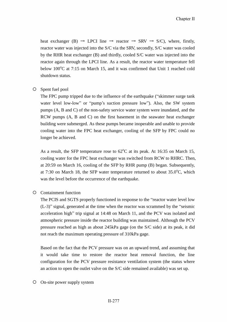
heat exchanger (B) → LPCI line → reactor → SRV → S/C), where, firstly,
reactor water was injected into the S/C via the SRV, secondly, S/C water was cooled
by the RHR heat exchanger (B) and thirdly, cooled S/C water was injected into the
reactor again through the LPCI line. As a result, the reactor water temperature fell
below 100oC at 7:15 on March 15, and it was confirmed that Unit 1 reached cold
shutdown status.
Spent fuel pool
The FPC pump tripped due to the influence of the earthquake (“skimmer surge tank
water level low-low” or “pump’s suction pressure low”). Also, the SW system
pumps (A, B and C) of the non-safety service water system were inundated, and the
RCW pumps (A, B and C) on the first basement in the seawater heat exchanger
building were submerged. As these pumps became inoperable and unable to provide
cooling water into the FPC heat exchanger, cooling of the SFP by FPC could no
longer be achieved.
As a result, the SFP temperature rose to 62oC at its peak. At 16:35 on March 15,
cooling water for the FPC heat exchanger was switched from RCW to RHRC. Then,
at 20:59 on March 16, cooling of the SFP by RHR pump (B) began. Subsequently,
at 7:30 on March 18, the SFP water temperature returned to about 35.0oC, which
was the level before the occurrence of the earthquake.
Containment function
The PCIS and SGTS properly functioned in response to the “reactor water level low
(L-3)” signal, generated at the time when the reactor was scrammed by the “seismic
acceleration high” trip signal at 14:48 on March 11, and the PCV was isolated and
atmospheric pressure inside the reactor building was maintained. Although the PCV
pressure reached as high as about 245kPa gage (on the S/C side) at its peak, it did
not reach the maximum operating pressure of 310kPa gage.
Based on the fact that the PCV pressure was on an upward trend, and assuming that
it would take time to restore the reactor heat removal function, the line
configuration for the PCV pressure resistance ventilation system (the status where
an action to open the outlet valve on the S/C side remained available) was set up.
On-site power supply system
Chapter II
II-277

Immediately after the reactor scram, all on-site power supply systems were
operable. However, due to the subsequent tsunamis, the emergency power supply
system (P/C 4C-2 and 4D-2) became inoperable because of the submergence of the
seawater heat exchanger building.
Emergency DGs (A and B systems, and HPCS system) were all operable
immediately after the reactor scram. However, after the tsunami strike, the
emergency DGs (A and B) became inoperable, as RHRS pumps (A, B, C and D),
EECW pumps (A and B) failed to be actuated.
In the course of the subsequent restoration, the load supplied to the inoperable
emergency power supply (P/C 4D-2), RHRC pump (B) and RHRS pump (D),
required for cooling down the reactor and the SFP, secured the power supply
through temporary cables installed from the power supply system of the seawater
heat exchanger building of Unit 3 (P/C 3D-2), and EECW pump (B) secured the
power supply from a high voltage power supply vehicle (with restoration work
conducted on March 14).
As the emergency DG (B) became operable, the emergency power supply unit
(M/C 4D) could receive power from the emergency DG (B) even in the case of a
loss of external power supply.
The main time-series data is shown in Table II-2-46. Statuses of ECCS components,
etc. are shown in Table II-2-47. A schematic view of the plant status is shown in
Figures II-2-122 and 123. The status of the single-line diagram is shown in Figure
II-2-124. Changes in major parameters are shown in Figures II-2-125 and 126.
Chapter II
II-278

2-46 Fukushima Dai-ni NPS, Unit 4 – Main Chronology (provisional)
* The information included in the table is subject to modifications following later verifications. The
table was established based on the information provided by TEPCO, but it may include unreliable
information due to tangled process of collectinginformation amid the emergency response. As for the
view of the Government of Japan, it is expressed in the body text of the report. Fukushima Dai-ni NPS
Unit 4
Operational Status before Earthquake: In operation
3/11 14:46 Earthquake ocuurred
14:48 All control rods were fully inserted
Reactor scram (large earthquake accelation)
Turbine trip
Shut down of one circuit of Tomioka Line ( Line 2 was stopped, Continued receipt of power by Line 1)
15:05 Confirmed reactor subcriticl
15:22 Observed first wave of tsunami (Subsequently several waves were observed intermittently until 17:14)
15:33 Manually stopped circulating water pump (CWP) (C)
Around15:34 Emergency diesel generator (Emergency DG) (A) (B) (H) automatically started / immediately DG (A) (B) stopped due to tsunami impact
15:35 CWP (A) (B) automatically stopped
15:36 Manually closed main steam isolation valves (MSIV)
Manually started residual heat removal system RHR (B) (Automatically stopped at 15:41)
15:37 Manually started RHR (A) (Automatically stopped at 15:38)
15:46 Started reactor depressurization (Safety relief valve (SRV) automatically opened) (Subsequently controlled reactor pressure by opening and
closing manually or automatically )
15:50 Iwado line completely stopped (Line 2 was stopped while line 1 had been down for maintenance before earthquake)
15:54 Manually started reactor core isolation cooling system (RCIC) (Subsequently started and stopped appropriately)
18:33 Determined that a notification event according to NEPA Article 10 ( loss of residual heat removal function) occurred
19:02 Alarm “Dry well high pressure ” was generated
19:14 Manually started dry well (D/W) cooling system
3/12 0:16 Manually stopped RCIC (Shutdown due to the pressure drop of reactor)
Strated alternative injection using makeup water condensate system (MUWC)
6:07 Licensee determined that a notification event according to NEPA Article 15 ( loss of pressure suppresion function) occurred due to suppersion
chamber water temperature exceeded 100 Cerisius
7:23 Performed S/C cooling by flammability gas control system (FCS) using makeup water pure water system (MUWP)
7:35 Performed S/C spray by using MUWC
11:17 Transffered reactor cooling from MUWC (alternative injection) to high pressure core spray (HPCS ) sytem
11:44 Started configuration of pressure vent line for primary containment vessel (PCV)
11:52 Completed configuration of pressure vent line for primary containment vessel (PCV)
Around13:38 Received electricity of one circuit of Iwado line (completed restoration of line 2)
13:48 Stopped reactor water injection by HPCS (Subsequently done appropriately)
3/13 Around5:15 Received electricity of two circuits of Iwado line (completed restoration of line 1)
12:43 Alarm “Control rod 10-19 Drift” was generated
3/14 11:00 Manually started emergency equipment cooling water sytem (EECW) (B) (Receiving power from high voltage power supply vehicle)
13:07 Manually started residual heat removal sea water system (RHRS) pump (D) (Temporary cabling from 480V emergency low voltage switch gear
(power center (P/C) 3D-2 for receiving power)
14:56 Manually started residual heat removal cooling water system (RHRC) pump (B) ( Motor replaced / Temporary cabling from P/C 3D-2)
15:42 Manually started RHR (B) (started S/C cooling mode)
Licensee determined that a notification event according to NEPA Article 10 ( loss of residual heat removal function) was restored by starting RHR
(B)
16:02 Started RHR (B) S/C spray mode
18:58 Started water injection to reactor by RHR (B) low pressure core injection (LPCI) mode (stopped at 19:02) (Subsequently started and stopped
appropriately)
20:19 Alarm “Control rod 10-19 Drift” was reset
21:07 Alarm “Control rod 10-19 Drift” was generated (Subsequently continued)
22:07 Licensee determined that a notification event according to NEPA Article 10 (increase of radiation dose at site boundary) occurred due to
monitoring post (No.1 ) exceeding 5 μ Gy/h (also monitoring post (No.3) at 0:12 on Mar.15) (assumed that it was due to the effect of radioactive
materials released to the atmosphere caused by Fukushima Dai-ichi NPS accident)
3/15 7:15 Determined that a notification event according to NEPA Article 15 ( loss of pressure suppresion function) was restored due to suppersion chamber
water temperaturedroped below 100 Cerisius
16:35 Switching fuel pool cooling and filitering system (FPC) heat exchanger cooling (reactor componet cooling water system (RCW)→ residual heat
removal component cooling water system (RHRC))
3/16 20:59 Started spent fuel pool (SFP) cooling by RHR (B)
3/17 11:24 Returned PCV vent ready status to normal
3/18 7:30 SFP water reached at around 32.5 Cerisius (returned to water temperature before earthquake)
3/19
3/20
3/21
3/22
3/23
3/24
3/25
3/26
3/27
3/28
3/29 10:52 Stopped RHR (B) (For maintenance of water intake)
14:04 Started RHR (B)
3/30
3/31 14:35 Stopped RHR (B) (For switching cooling mode (reactor shut down cooling mode (SHC) + S/C cooling mode → SHC mode + S/C cooling mode +
fuel pool cooling mode)
15:36 Started RHR (B)
4/1
4/2
4/3
4/4
4/5
4/6
4/7
4/8
4/9
Chapter II
II-279

4/10
4/11
4/12
4/13
4/14
4/15 Around17:43 Received electricity of two circuits of Tomioka line (completed restoration of line 2)
4/16
4/17
4/18
4/19
4/20
4/21
4/22
4/23
4/24
4/25
4/26
4/27 10:20 Stopped RHR (B) (for switching of power supply)
17:41 Started RHR (B)
4/28
4/29
4/30
5/1
5/2
5/3
5/4
5/5
5/6
5/7
5/8
5/9
5/10
5/11
5/12
5/13
5/14
5/15
5/16
5/17
5/18
5/19
5/20
5/21
5/22
5/23
5/24
5/25
5/26
5/27
5/28
5/29
5/30
5/31
6/1
6/2
6/3
6/4
6/5 10:01 Stopped RHR (B) (for change of cooling mode (LPCI mode → reactor shut down cooling (SHC) mode))
11:14 Started RHR (B)
6/6
6/7 Around16:00 Found air leakage at main exhaust duct and confirmed that the air was equivalent to the outside air after measurement
6/8 Around18:10 Found oil film at around water discharge of Unit 3 and 4
Took measures to prevent spreading of oil by installing oil fence, using oil absorption sheets
(Skipped)
6/30 9:53 Stopped RHR (B) (for sitching power cables for RHRC pumps (B) (D))
16:32 Started RHR (B)
(Skipped)
7/8 9:40 Stopped RHR (B) (for sitching power cables for RHRC pumps (B) (D))
16:38 Started RHR (B)
(Skipped)
7/31 6:32 Found air leakage at main exhaust duct and confirmed that the air was equivalent to the outside air after measurement
8/1
8/2 12:24 Cnfirmed integrity of RHR (A) by RHR (A) trial operation
8/3 22:33 Stopped RHR (B) (for switching to RHR pump (A))
23:00 Started RHR pump (A)
(Skipped)
8/31
Chapter II
II-280

Table II-2-47 Status of Emergency Core Cooling System Equipment etc.[2F-4]
Installed
place
Seismic
class
When the
reactor
scrammed
Till just before
tsunami arrived
after rector scram
Till cold
shutdown
after
tsunami
arrival
Remarks
Cooling
Function
ECCS etc.
RHR(A) R/B 2nd
basement (o.p.0000)
A ○ ◎ × Unavailable because RHRS, RHRC and EECW became unoperable due to tsunami. No damage on the pump body
LPCS R/B 2nd
basement (o.p.0000)
A ○ ○ × Unavailable because RHRS, RHRC and EECW became unoperable due to tsunami. No damage on the pump body
RHRC(A) Hx/B 1st
floor (o.p.4200)
A ○ ◎ × Unavailable because power supply equipment and motor was submerged and unoperable due to tsunami
RHRC(C) Hx/B 1st
floor (o.p.4200)
A ○ ◎ × Unavailable because power supply equipment and motor was submerged and unoperable due to tsunami
RHRS(A) Hx/B 1st
floor (o.p.4200)
A ○ ◎ × Unavailable because power supply equipment and motor was submerged and unoperable due to tsunami
RHRS(C) Hx/B 1st
floor (o.p.4200)
A ○ ◎ × Unavailable because power supply equipment and motor was submerged and unoperable due to tsunami
EECW(A) Hx/B 1st
floor (o.p.4200)
A ○ ◎ × Unavailable because power supply equipment and motor was submerged and unoperable due to tsunami
RHR(B) R/B 2nd
basement (o.p.0000)
A ○ ◎ ×→◎
Unavailable because RHRS, RHRC and EECW became unoperable due to tsunami. No damage on the pump body. Started operation after recovery of RHRS, RHRC and EECW on Mar. 14
RHR(C) R/B 2nd
basement (o.p.0000)
A ○ ○ ×→○
Unavailable because RHRS, RHRC and EECW became unoperable due to tsunami. No damage on the pump body. Became standby after recovery of RHRS, RHRC and EECW on Mar. 14
RHRC(B) Hx/B 1st
floor (o.p.4200)
A ○ ◎ ×→◎
Unavailable because power supply equipment and motor was submerged and unoperable due to tsunami. Temporary cabling from Hx/B of Unit 3 and started operation after replacement of motor on Mar. 14.
RHRC(D) Hx/B 1st
floor (o.p.4200)
A ○ ◎ × Unavailable because power supply equipment and motor was submerged and unoperable due to tsunami.
RHRS(B) Hx/B 1st
floor (o.p.4200)
A ○ ◎ × Unavailable because power supply equipment and motor was submerged and unoperable due to tsunami.
RHRS(D) Hx/B 1st
floor (o.p.4200)
A ○ ◎ ×→◎
Unavailable because power supply equipment was submerged and unoperable due to tsunami. No damage on the pump body. Temporary cabling from Hx/B of Unit 3 and started operation on Mar. 14.
EECW(B) Hx/B 2nd
floor (o.p.11200)
A ○ ◎ ×→◎
Unavailable because power supply equipment was submerged and unoperable due to tsunami. No damage on the pump body. Temporary cabling from high voltage power supply vehicle and started operation on Mar. 14.
HPCS R/B 2nd
basement (o.p.0000)
A ○ ◎ ○→◎→○ Injected water appropriately from Mar. 12 and became standby on Mar. 14.
HPCSC Hx/B 1st
floor (o.p.4200)
A ○ ◎ ◎
HPCSS Hx/B 1st
floor (o.p.4200)
A ○ ◎ ◎
Water
Injection
to
Reactor
RCIC R/B 2nd
basement (o.p.0000)
A ○ ◎ ◎→○ Started operation after tsunami and stopped due to reactor pressure drop on Mar. 12.
MUWC
(Alternative
Injection)
T/B 2nd basement
(o.p.-2000) B ○ ○ ○→◎→○
Operated on Mar. 12 and became stand by on Mar. 14.
Pool
Cooling
SFP Cooling
(FPC)
R/B 4th floor (o.p.31800) B ◎ ×
×→◎→○
→◎
Unavailable due to trip by earthequake and RCW unoperable due to tsunami. Started operation on Mar. 15 (the cooling water of FPC Hx was supplied by RHRC). Became standby on Mar. 16.
SFP Cooling
(RHR)
R/B 2nd basement (o.p.0000)
A ○ ○ ×→○→◎
→○
Unavailable because RHRS, RHRC and EECW was unoperable due to tsunami. Started operation after recovery of RHRS, RHRC and EECW on Mar. 16 (FPC auxiliary cooling mode). Became stndby on June 5.
Confine-
ment
Function
Cantain-
ment
Facility
Reactor
Building A ○ ○ ○
Maintain negative pressure and observe no sign of damage.
Primary
Containment
Vessel
As ○ ○ ○
Observe no sign of damage regarding PCV presuure
(Legend) ◎:in operation ○:stand by ×:Loss of Function or Outage
Chapter II
II-281

Figure II-2-122 Schematic Diagram of Station Status [2F-4] (Part 1)
海
RHR
ポンプ(A)
圧力抑制室
RHR
熱交換器(A)
RHR
ポンプ(C)
RHR
ポンプ(B)
RHR
熱交換器(B)
海
※2※1
RHRCポンプ(B)系
RHRCポンプ(A)系
EECWポンプ(B)
EECWポンプ(A)
A
C
B
D
RHRSポンプ(A)系
C
A
RHRSポンプ(B)系
D
B
ポンプ(A系)の電源系
ポンプ(B系)の電源系
4号機-(1)3月11日
地震発生~津波到達前まで
タービン
※3
※3
使用済燃料
プールへ
HPCSSポンプHPCSCポンプ
※5:熱交換器
※4
※4
※5
※5:SFPより
MUWC
MUWC
【他非常用炉心冷却系状態】・HPCS ○
・LPCS ○
・RCIC ○原子炉格納容器
熱交換器
熱交換器
熱交換器
熱交換器
熱交換器
熱交換器
熱交換器
○:使用中
○:待機中
×:使用不能
外部電源
常用電源系
海
RHR
ポンプ(A)
圧力抑制室
RHR
熱交換器(A)
RHR
ポンプ(C)
RHR
ポンプ(B)
RHR
熱交換器(B)
海
※2※1
※2
RHRCポンプ(B)系
RHRCポンプ(A)系
EECWポンプ(B)
EECWポンプ(A)
A
C
B
D
RHRSポンプ(A)系
C
RHRSポンプ(B)系
D
B
ポンプ(A系)の電源系
ポンプ(B系)の電源系
4号機-(2)3月11日津波到達後のプラント状況
タービン
※3
※3
使用済燃料
プールへ
HPCSSポンプHPCSCポンプ
※4
※4
※5
※5:SFPより
MUWC
MUWC
【他非常用炉心冷却系状態】・HPCS ○
・LPCS ×
原子炉格納容器
×
××
×
×
×
××
×
×××
×
×
熱交換器
熱交換器
熱交換器
熱交換器
熱交換器
熱交換器
熱交換器
○:使用中
○:待機中
×:使用不能
外部電源
常用電源系
原子炉圧力容器
原子炉圧力容器
MSIV
MSIV
FCS冷却水
(MUWP)
FCS冷却水
(MUWP)
海水熱交換器建屋
※2
※1
D/G(A)設備冷却
RHR,LPCS機器冷却
RHR,LPCS機器冷却
RHR機器冷却
非常用電源系
D/G(A) D/G(B) D/G(HPCS)M/C 4C M/C 4D M/C 4HPCS
SRV
海水熱交換器建屋
RHR,LPCS機器冷却
D/G(HPCS)設備冷却
HPCS機器冷却
D/G(B)設備冷却
RHR機器冷却
RHR機器冷却
D/G(A)設備冷却
RHR,LPCS機器冷却
※1
非常用電源系
D/G(A) D/G(B) D/G(HPCS)M/C 4C M/C 4D M/C 4HPCS
非常用電源系
D/G(A) D/G(B) D/G(HPCS)M/C 4C M/C 4D M/C 4HPCS
非常用電源系
D/G(HPCS)M/C 4C M/C 4D M/C 4HPCS
× ×
SRV
A
×
RCIC
D/G(HPCS)設備冷却
HPCS機器冷却
D/G(B)設備冷却
RHR機器冷却
Unit 4-(1)March 11After earthquake until just before tsunami reached
Seawater heat exchanger building
Power supply system
for Pump A systems
【Status of other emergency core cooling systems 】
Primary Containment Vessel
To Spent Fuel Pool
To TurbineRPV
FCS cooling water
SuppressionPool
RHR Heat exchanger (A)
RHR pump (C)
RHR pump (A) RHR pump (B)
RHR Heat exchanger (B)
From SFPIn Operation
Stand-by
Disabled
NormalPower Supply
ExternalPower
EmergencyPower Supply
Cooling D/G (A) facilitiesCooling RHR, LPCS equipment
Cooling RHR, LPCS equipment
Cooling D/G HPCS) facilities, CoolingHPCS equipment
Cooling D/G (B) facilitiesCooling RHR equipment
Cooling RHRequipment
EECW pump A
RHRC pump A system
HPCSC pump
EECW pump B
RHRC pump B system
Heat
exchanger
Heat
exchanger
Heat
exchanger
Heat
exchanger
Heat
exchanger
Heat
exchanger
Heat
exchanger
Heat
exchanger
RHRS pump A system
Sea
HPCSS pump
RHRS pump B system
SeaPower supply system
for Pump B systems
Unit 4-(2)March 11After tsunami reached
【Status of other emergencycore cooling systems 】
Primary Containment Vessel
RPV
FCS cooling water
SuppressionPool
RHR Heat exchanger (A)
RHR pump (A)
RHR pump (C)RHR Heat
exchanger (B)
RHR pump (B)
From SFP
Disabled
Stand-by
In Operation
NormalPower Supply
ExternalPower
EmergencyPower Supply
To Turbine
To Spent Fuel Pool
Cooling D/G (A) facilitiesCooling RHR, LPCS equipment
Cooling RHR, LPCS equipment
Cooling D/G HPCS) facilities, CoolingHPCS equipment
Cooling D/G (B) facilitiesCooling RHR equipment
Cooling RHRequipment
Seawater heat exchanger building
Power supply system
for Pump A systems
Heat
exchanger
Heat
exchanger
Heat
exchanger
Heat
exchanger
Heat
exchanger
Heat
exchanger
Heat
exchanger
RHRC pump A system
EECW pump A
RHRS pump A system
HPCSC pump
EECW pump B
RHRC pump B system
Power supply system
for Pump B systems
HPCSS pump
RHRS pump B system
Sea
Sea
Chapter II
II-282

Figure II-2-123 Schematic Diagram of Station Status [2F-4] (Part 2)
海
RHR
ポンプ(A)
圧力抑制室
RHR
熱交換器(A)
RHR
ポンプ(C)
RHR
ポンプ(B)
RHR
熱交換器(B)
海
※2※1RHRCポンプ(B)系
RHRCポンプ(A)系
EECWポンプ(B)
EECWポンプ(A)
A
C
B
D
C
A
RHRSポンプ(B)系
D
B
ポンプ(A系)の電源系
ポンプ(B系)の電源系
4号機-(3)3月14日RHRSポンプ,RHRCポンプ
電源復旧時のプラント状況(S/Pスプレイ)
タービン
※3
※3
使用済燃料
プールへ
HPCSSポンプHPCSCポンプ
※4
※4
※5
※5:SFPより
MUWC
MUWC
【他非常用炉心冷却系状態】・HPCS ○
・LPCS ×
・RCIC ×原子炉格納容器
×
×
×
× 仮設電源
(P/C3D-2使用)
仮設電源
(P/C3D-2使用)
×
×
××
×
×
仮設電源
(高圧電源車使用)
熱交換器
熱交換器
熱交換器
熱交換器
熱交換器
熱交換器
熱交換器
○:使用中
○:待機中
×:使用不能
外部電源
常用電源系
海
RHR
ポンプ(A)
圧力抑制室
RHR
熱交換器(A)
RHR
ポンプ(C)
RHR
ポンプ(B)
RHR
熱交換器(B)
海
※2※1
RHRCポンプ(B)系
RHRCポンプ(A)系
EECWポンプ(B)
EECWポンプ(A)
A
C
B
D
RHRSポンプ(A)系
C
A
RHRSポンプ(B)系
D
B
ポンプ(A系)の電源系
ポンプ(B系)の電源系
4号機-(4)3月15日 7:15
冷温停止時
タービン
使用済み燃料
プールへ
HPCSSポンプHPCSCポンプ
※4
※4
※5
※5:SFPより
MUWC
MUWC
【他非常用炉心冷却系状態】・HPCS ○
・LPCS ×
・RCIC ×原子炉格納容器
×
×
仮設電源
(P/C3D-2使用)
仮設電源
(P/C3D-2使用)
×
×
××
×
×
仮設電源
(高圧電源車使用)
熱交換器
熱交換器
熱交換器
熱交換器
熱交換器
熱交換器
熱交換器
○:使用中
○:待機中
×:使用不能
外部電源
常用電源系
×
×
原子炉圧力容器
原子炉圧力容器
MSIV
MSIV
RHRSポンプ(A)系
FCS冷却水
(MUWP)
FCS冷却水
(MUWP)
※2
RHR,LPCS機器冷却
D/G(HPCS)設備冷却
HPCS機器冷却
D/G(B)設備冷却
RHR機器冷却
RHR機器冷却
D/G(A)設備冷却
RHR,LPCS機器冷却
※1
非常用電源系
D/G(HPCS)M/C 4C M/C 4D M/C 4HPCS
非常用電源系
D/G(A) D/G(B)M/C 4C M/C 4D M/C 4HPCS
×
海水熱交換器建屋
海水熱交換器建屋
※2
RHR,LPCS機器冷却
D/G(HPCS)設備冷却
HPCS機器冷却
D/G(B)設備冷却
RHR機器冷却
RHR機器冷却
D/G(A)設備冷却
RHR,LPCS機器冷却
※1
非常用電源系
D/G(HPCS)M/C 4C M/C 4D M/C 4HPCS
非常用電源系
D/G(A) D/G(B)M/C 4C M/C 4D M/C 4HPCS
×
SRV
SRV
【Status of other emergency core cooling systems 】
Unit 4-(3)March 14, Plant Condition when power supply for RHRS pumps and RHRC pumps restored
RPV To Turbine
Primary Containment Vessel
To Spent Fuel Pool
SuppressionPool
FCS cooling waterFCS cooling water
RHR pump (C)
RHR pump (A)
RHR Heat exchanger (A)
RHR pump (B)
From SFP
RHR Heat exchanger (B)
In Operation
Stand-by
DisabledNormal
Power Supply
ExternalPower
Power supply system
for Pump A systems
EECW pump A
RHRC pump A system
RHRS pump A system
HPCSC pump HPCSS pump
Sea
Seawater heat exchanger building
Cooling D/G (A) facilitiesCooling RHR, LPCS equipment
Cooling D/G (B) facilitiesCooling RHR equipment
Cooling RHR, LPCS equipment
Cooling RHRequipment
Cooling D/G HPCS) facilities, CoolingHPCS equipment
Heat
exchanger
Heat
exchanger
Heat
exchanger
Heat
exchanger
Heat
exchanger
Heat
exchanger
Heat
exchanger
Sea
Sea
Power supply system
for Pump B systems
Power supply system
for Pump B systems
RHRC pump B system
EECW pump B
RHRS pump B system
EmergencyPower Supply
【Status of other emergencycore cooling systems 】
Primary Containment Vessel
RPV
FCS cooling water
RHR Heat exchanger (A)
Disabled
Stand-by
In Operation
RHR pump (A)
RHR pump (C)
From SFP
RHR pump (B)
RHR Heat exchanger (B)
NormalPower Supply
ExternalPower
EmergencyPower Supply
To Turbine
To Spent Fuel Pool
Cooling D/G (A) facilitiesCooling RHR, LPCS equipment
Cooling RHR, LPCS equipment
Cooling D/G HPCS) facilities, CoolingHPCS equipment
Cooling D/G (B) facilitiesCooling RHR equipment
Cooling RHRequipment
Seawater heat exchanger building
Power supply system
for Pump A systems
EECW pump A
RHRC pump A system
HPCSC pump
EECW pump B
RHRC pump B system
Heat
exchanger
Heat
exchanger
Heat
exchanger
Heat
exchanger
Heat
exchanger
Heat
exchanger
Heat
exchanger
Sea
RHRS pump A system
RHRS pump B system
HPCSS pump
Temporary power supply
(Using high-voltage
power supply vehicle)
Temporary power supply
(Using P/C3D-2)
Temporary power
supply
(Using P/C3D-2)
SuppressionPool
Temporary power supply
(Using high-voltage
power supply vehicle)
Temporary power supply
(Using P/C3D-2)
Temporary power
supply
(Using P/C3D-2)
Unit 4-(4)March 14, 17:00
At cold shutdowm
Chapter II
II-283

Figure II-2-124 Status of Single-line Diagram of Emergency Power Supply System [2F-4]
※13 ※14 ※15 ※16
6.9kV M/C
1SA-16.9kV M/C
1SA-2
起動変圧器
1SA
電気ボイラー用
66kV開閉所
66kV起動用開閉所
66kV 岩井戸線
1号 2号
高起動
変圧器
2号機 3号機 4号機1号機
G G G
6.9kV M/C
1SB-16.9kV M/C
1SB-2
起動変圧器
1SB
500kV 富岡線
1号 2号
6.9kV M/C
3SA-16.9kV M/C
3SA-2
起動変圧器
3SA
6.9kV M/C
3SB-1
6.9kV M/C
3SB-2
起動変圧器
3SB
※1 ※2 ※3 ※4 ※5 ※6 ※7 ※8 ※9 ※10 ※11 ※12480V P/C
1WB-1
3/12 13:38
受電
3/13 5:15
受電
D/G
HPCSポンプ
HPCSCポンプ
HPCSSポンプ
D/G(HPCS)
6.9kV M/C
4HPCS
※8
MCC
4HPCS
D/G
RHRポンプ(
A)
RHRCポンプ(
A)
RHRCポンプ(
C)
D/G(A)
6.9kV M/C 4C
※10
480kV P/C
4C-1
LPCSポンプ
480kV P/C
4C-2
RHRSポンプ(
A)
RHRSポンプ(
C)
D/G
RHRポンプ(
C)
RHRCポンプ(
B)
RHRCポンプ(
D)
D/G(B)
6.9kV M/C 4D
※12
480kV P/C
4D-1
RHRポンプ(
B)
480kV P/C
4D-2
RHRSポンプ(
B)
RHRSポンプ(
D)
EECWポンプ(
A)
EECWポンプ(
B)
4号機
無負荷運転中
(3/11 津波到達以降)
D/G
HPCSポンプ
HPCSCポンプ
HPCSSポンプ
D/G(HPCS)
6.9kV M/C
4HPCS
※8
MCC
4HPCS
D/G
RHRポンプ(
A)
RHRCポンプ(
A)
RHRCポンプ(
C)
D/G(A)
6.9kV M/C 4C
※10
480kV P/C
4C-1
LPCSポンプ
480kV P/C
4C-2
RHRSポンプ(
A)
RHRSポンプ(
C)
D/G
RHRポンプ(
C)
RHRCポンプ(
B)
RHRCポンプ(
D)
D/G(B)
6.9kV M/C 4D
※12
480kV P/C
4D-1
RHRポンプ(
B)
480kV P/C
4D-2
RHRSポンプ(
B)
RHRSポンプ(
D)
EECWポンプ(
A)
EECWポンプ(
B)
4号機
無負荷運転中
(3/15 7:15 冷温停止)
※19
P/C
3D-2
※18
P/C
3D-2
高圧
電源車
G
被水により使用不能
充電状態
遮断器「投入」状態
遮断器「開放」状態(待機)
仮設ケーブル
運転中の機器赤字
遮断器「開放」状態(故障時)
非常用電源系 単線結線図 (4号機 津波到達時及び冷温停止時の状態)
Line 1 Line 2
Unit 1 Unit 2 Unit 3 Unit 4
High startup transformer
66kV substation for electric boilers
March 13, 5:15Received electricity
66kV substation for startup
Unit 2 March 12, 13:38
Received electricity
Unit 1 Breaker “Close” status
Breaker “Open” status (standby)
Breaker “Open” status (failed)
Energized
Temporary cabling
In red – Equipment in Operation
Unavailable due to submerging
Startup transformer
Startup transformer
Startup transformer Startup transformer
Single-line Diagram of Emergency Power Supply System (Unit 4, Status When Tsunami Reached and Cold Shutdown)
HPCS
P HPCSC
P
HPCSS
P
LPCS
P
RHR
P
(A) E E CW
P
(A)
R H R C
P
(A)
R H R C
P
(C)
R H R S
P
(A)
R H R S
P
(C)
R H R
P
(B)
R H R
P
(C)
HPCS
P HPCSC
P
HPCSS
P
LPCS
P
RHR
P
(A) E E CW
P
(A)
R H R C
P
(A)
R H R C
P
(C)
R H R S
P
(A)
R H R S
P
(C)
R H R
P
(B)
R H R
P
(C)
E E C W
P
(B)
E E C W
P
(B)
R H R C
P
(B)
R H R C
P
(B)
R H R C
P
(D)
R H R C
P
(D)
R H R S
P
(B)
R H R S
P
(B)
R H R S
P
(D)
R H R S
P
(D)
High-voltage power supply vehicle
500kV Tomioka Line 66kV Iwaido line
Unit 4 (March 11 After tsunami reached)
Unit 4 (March 15 7:15 Cold shutdown)
at no load operation
at no load operation
※13 ※14 ※15 ※16
6.9kV M/C
1SA-16.9kV M/C
1SA-2
起動変圧器
1SA
電気ボイラー用
66kV開閉所
66kV起動用開閉所
66kV 岩井戸線
1号 2号
高起動
変圧器
2号機 3号機 4号機1号機
G G G
6.9kV M/C
1SB-16.9kV M/C
1SB-2
起動変圧器
1SB
500kV 富岡線
1号 2号
6.9kV M/C
3SA-16.9kV M/C
3SA-2
起動変圧器
3SA
6.9kV M/C
3SB-1
6.9kV M/C
3SB-2
起動変圧器
3SB
※1 ※2 ※3 ※4 ※5 ※6 ※7 ※8 ※9 ※10 ※11 ※12480V P/C
1WB-1
3/12 13:38
受電
3/13 5:15
受電
D/G
HPCSポンプ
HPCSCポンプ
HPCSSポンプ
D/G(HPCS)
6.9kV M/C
4HPCS
※8
MCC
4HPCS
D/G
RHRポンプ(
A)
RHRCポンプ(
A)
RHRCポンプ(
C)
D/G(A)
6.9kV M/C 4C
※10
480kV P/C
4C-1
LPCSポンプ
480kV P/C
4C-2
RHRSポンプ(
A)
RHRSポンプ(
C)
D/G
RHRポンプ(
C)
RHRCポンプ(
B)
RHRCポンプ(
D)
D/G(B)
6.9kV M/C 4D
※12
480kV P/C
4D-1
RHRポンプ(
B)
480kV P/C
4D-2
RHRSポンプ(
B)
RHRSポンプ(
D)
EECWポンプ(
A)
EECWポンプ(
B)
4号機
無負荷運転中
(3/11 津波到達以降)
D/G
HPCSポンプ
HPCSCポンプ
HPCSSポンプ
D/G(HPCS)
6.9kV M/C
4HPCS
※8
MCC
4HPCS
D/G
RHRポンプ(
A)
RHRCポンプ(
A)
RHRCポンプ(
C)
D/G(A)
6.9kV M/C 4C
※10
480kV P/C
4C-1
LPCSポンプ
480kV P/C
4C-2
RHRSポンプ(
A)
RHRSポンプ(
C)
D/G
RHRポンプ(
C)
RHRCポンプ(
B)
RHRCポンプ(
D)
D/G(B)
6.9kV M/C 4D
※12
480kV P/C
4D-1
RHRポンプ(
B)
480kV P/C
4D-2
RHRSポンプ(
B)
RHRSポンプ(
D)
EECWポンプ(
A)
EECWポンプ(
B)
4号機
無負荷運転中
(3/15 7:15 冷温停止)
※19
P/C
3D-2
※18
P/C
3D-2
高圧
電源車
G
被水により使用不能
充電状態
遮断器「投入」状態
遮断器「開放」状態(待機)
仮設ケーブル
運転中の機器赤字
遮断器「開放」状態(故障時)
非常用電源系 単線結線図 (4号機 津波到達時及び冷温停止時の状態)
Line 1 Line 2
Unit 1 Unit 2 Unit 3 Unit 4
High startup transformer
66kV substation for electric boilers
March 13, 5:15Received electricity
66kV substation for startup
Unit 2 March 12, 13:38
Received electricity
Unit 1 Breaker “Close” status
Breaker “Open” status (standby)
Breaker “Open” status (failed)
Energized
Temporary cabling
In red – Equipment in Operation
Unavailable due to submerging
Startup transformer
Startup transformer
Startup transformer Startup transformer
Single-line Diagram of Emergency Power Supply System (Unit 4, Status When Tsunami Reached and Cold Shutdown)
HPCS
P HPCSC
P
HPCSS
P
LPCS
P
RHR
P
(A) E E CW
P
(A)
R H R C
P
(A)
R H R C
P
(C)
R H R S
P
(A)
R H R S
P
(C)
R H R
P
(B)
R H R
P
(C)
HPCS
P HPCSC
P
HPCSS
P
LPCS
P
RHR
P
(A) E E CW
P
(A)
R H R C
P
(A)
R H R C
P
(C)
R H R S
P
(A)
R H R S
P
(C)
R H R
P
(B)
R H R
P
(C)
HPCS
P HPCSC
P
HPCSS
P
LPCS
P
RHR
P
(A) E E CW
P
(A)
R H R C
P
(A)
R H R C
P
(C)
R H R S
P
(A)
R H R S
P
(C)
R H R
P
(B)
R H R
P
(C)
HPCS
P HPCSC
P
HPCSS
P
LPCS
P
RHR
P
(A) E E CW
P
(A)
R H R C
P
(A)
R H R C
P
(C)
R H R S
P
(A)
R H R S
P
(C)
R H R
P
(B)
R H R
P
(C)
E E C W
P
(B)
E E C W
P
(B)
R H R C
P
(B)
R H R C
P
(B)
R H R C
P
(D)
R H R C
P
(D)
R H R S
P
(B)
R H R S
P
(B)
R H R S
P
(D)
R H R S
P
(D)
High-voltage power supply vehicle
500kV Tomioka Line 66kV Iwaido line
Unit 4 (March 11 After tsunami reached)Unit 4 (March 11 After tsunami reached)
Unit 4 (March 15 7:15 Cold shutdown)Unit 4 (March 15 7:15 Cold shutdown)
at no load operation
at no load operation
Chapter II
II-284

-1000
-500
0
500
1000
1500
3/11 3/12 3/13 3/14 3/15 3/16 3/17 3/18 3/19
原子炉水位(広帯域)(mm)
(mm)
オーバースケール
Fig. II-2-125 Variation of major parameters [2F-4] (from March 11 to 19) (1)
Beyond scale
Reactor level (wide range) (mm)
Reactor pressure (MPa[gage])
Chapter II
II-285

0
10
20
30
40
50
60
70
3/11 3/12 3/13 3/14 3/15 3/16 3/17 3/18 3/19
燃料プール表面温度(℃)
FPCポンプ入口温度(℃)
(℃)
FPCポンプ停止 FPCポンプ停止
Fig. II-2-126 Variation of major parameters [2F-4] (from March 11 to 19) (2)
Fuel pool surface temperature (oC)
FPC pump inlet temperature (oC)
FPC pump stopped
S/C pressure (kPa[gage])
S/C water temperature (oC)
FPC pump stopped
Chapter II
II-286

5) Changes in major parameters
Records of the operation limits including design values, and maximum (minimum)
values are shown in Table II-2-48. The S/C temperatures at Units 1, 2 and 4 exceeded
the maximum operating temperature because the function to remove residual heat was
temporarily lost in these units. However, it was confirmed that other parameters were
within the range of fluctuation of the design values and operation limits.
TableII-2-48 Summary of Major Plant Parameters
for Fukushima Dai-ni Nuclear Power Station
Design/
operating limits
Maximum (minimum) value
Unit 1 Unit 2 Unit 3 Unit 4
Reactor water level
below 4196mm (from TAF level)
Approx.-
520mm(TAF+Approx.3676mm)
Approx.-
290mm(TAF+Approx.3906mm)
Approx.
+50mm(TAF+Approx.4146mm)
Approx.-
300mm(TAF+Approx.3896mm)
Reactor pressure
8.62MPa[gage]
(Maximum operating
pressure)
Approx. 7.35MPa [gage]
Approx. 7.35MPa [gage]
Approx. 7.35MPa [gage]
Approx. 7.35MPa [gage]
Raactor
containment
pressure
310kPa[gage]
(Maximum operating
pressure)
Approx. 282kPa[gage]
Approx. 279kPa[gage]
Approx. 38kPa[gage]
Approx. 245kPa[gage]
Surppression chamber
temperature
104℃
(Maximum operating
temperature)
Approx. 130℃ Approx. 139℃ Approx. 66℃ Approx. 137℃
Surppression chamber water
level
(from the zero
point of
surppression
pool water gauge)
Unit 1:
below +8127mm Unit 2:
below +8050mm
Unit 3:
below +6300mm
Unit 4:
below +8050mm (S/C ベントライン高さ)
Approx.+7418mm Approx.+5400mm Approx.+798mm Approx. +5600mm
Fuel pool water
temperature
below 65℃
(Operational Safety
Program)
Approx. 62℃ Approx. 56℃ Approx. 51℃ Approx. 62℃
Chapter II
II-287

6) Influence of radioactive materials upon the off-site environment
Concerning the reactor water level, TAF was secured at all the units although the
reactor cooling function was temporarily lost in Units 1, 2 and 4. Concerning the SFP,
the limiting condition for operation (LCO) (SFP water level: around the overflow level,
water temperature: at or below 65oC) specified in the operational safety program of the
nuclear facility was satisfied, although the cooling function had been lost temporarily.
Measurements of the reactor water and SFP water are shown in Tables II-2-49 and 50.
No value indicating the possibility of fuel damage was detected. Based on these data,
we judge that fuel damage in the reactor and the SFP due to the earthquake did not
occur.
After the earthquake, the Cs-137 concentration in the SFP water at Unit 1 slightly
exceeded the detection limit. When the measurement was made, circulation cooling of
reactor water and SFP water via RHR was being conducted, and thus these two types of
water had a uniform quality. As illustrated by I-131, fission products originating from
natural uranium contained in the fuel cladding exists in the reactor water. During normal
plant operation, these fission products are removed by the reactor purification system so
that a fixed concentration is not exceeded. We presume that the concentration of Cs-137
slightly exceeding the detection limit was observed because the reactor coolant
purification system and the spent fuel pool purification system were both shut down due
to the influence of the earthquake. At subsequent measurements of the SFP water at Unit
1, the Cs-137 concentration was below the detection limit.
It was observed that the concentrations of Cs-137 in the reactor water and the SFP water
at Unit 2 increased after the earthquake. In the SFP of Unit 2, there existed two fuel
assemblies for which leakage had been confirmed in 1997 and 2002. Thus, Cs-137
(having a half-life of roughly 30 years) had been detected in the SFP water even before
the earthquake. Therefore, we presume that the reason behind such an increase was
partly because the SFP water entered into the reactor water when the circulation cooling
by RHR was conducted after the earthquake, and also because the purification systems
of the reactor water and the SFP water stopped due to the influence of the earthquake.
Furthermore, there were no irregularities in the function to contain radioactive materials,
because the PCV was isolated and sub-atmospheric pressure was maintained at the
reactor building by the proper actuation of PCIS and continuous operation of SGTS.
Chapter II
II-288

Among the MPs from No.1 to No. 7, which show the radiation dose at the site boundary
of Fukushima Dai-ni NPS, the limit of 5μSv/h was exceeded at No.1 at 22:07 on
March 14 and No. 3 on the site boundaryat 0:12 on March 15, respectively. Therefore, it
was judged that the situation corresponded to a “rise of radiation dose at the site
boundary” event in accordance with Article 10 of the Special Law of Emergency
Preparedness for Nuclear Disaster. However, it is presumed that this event was not
caused by Fukushima Dai-ni NPS, but by the influence of radioactive materials being
released associated with the accident at Fukushima Dai-ichi NPS.
The measurements at MP No. 1 and No. 3 rose and stabilized and then continued to fall
to below 5μSv/h at 9:30 on April 3. Further continuous monitoring showed that the
radiation dose was kept below 5μSv/h and there was no significant change.
Consequently it was judged that the NPS was recovered from the situation (rise of
radiation dose at the site boundary) corresponding to Article 10 of the Special Law of
Emergency Preparedness for Nuclear Disaster at 8:23 on April 8.
Fig. II-2-127 shows the measurements of MPs taken in the period between the
occurrence of the earthquake and the establishment of cold shutdown.
Chapter II
II-289

Table II-2-49 Rusults of Measurement of I-131, Cs-134 and Cs-137 Concentration in
Reactor Water
Table II-2-50 Rusults of Measurement of I-131, Cs-134 and Cs-137 Concentration in
Spent Fuel Pool Water
1号機 I-131検出限界値未満
<3.11×10⁻³
検出限界値未満
<3.09×10⁻²
Cs-134検出限界値未満
<5.12×10⁻³
検出限界値未満
<4.86×10⁻²
Cs-137検出限界値未満
<4.92×10⁻³
検出限界値未満
<4.60×10⁻²
2号機 I-131検出限界値未満
<3.49×10⁻³
検出限界値未満
<2.59×10⁻²
Cs-134検出限界値未満
<5.37×10⁻³
検出限界値未満
<5.33×10⁻²
Cs-137 4.10×10⁻³
1.82×10⁻¹
3号機 I-131検出限界値未満
<4.08×10⁻³
検出限界値未満
<7.55×10⁻³
Cs-134検出限界値未満
<6.86×10⁻³
検出限界値未満
<1.26×10⁻²
Cs-137検出限界値未満
<5.51×10⁻³
検出限界値未満
<1.21×10⁻²
4号機 I-131検出限界値未満
<2.71×10⁻³
検出限界値未満
<4.00×10⁻²
Cs-134検出限界値未満
<1.54×10⁻²
検出限界値未満
<7.49×10⁻²
Cs-137検出限界値未満
<3.99×10⁻³
検出限界値未満
<6.38×10⁻²
採取日時3/2 9:30
採取日時5/15 9:55 ※
採取日時3/2 9:45
採取日時5/15 11:05
採取日時3/2 10:00
採取日時4/28 12:20 ※
地震前 地震後
採取日時3/2 10:15
採取日時7/22 14:45
※ RHR系により、原子炉及び使用済燃料プールを循環冷却していたため、原子炉水及び
使用済燃料プール水の値が同一となる。
1号機 I-131 2.00×10⁻² 検出限界値未満
<1.13×10⁻¹
Cs-134検出限界値未満
<1.93×10⁻¹
検出限界値未満
<3.83×10⁻¹
Cs-137検出限界値未満
<6.72×10⁻²
検出限界値未満
<1.87×10⁻¹
2号機 I-131 1.71×10⁻² 検出限界値未満
<2.59×10⁻²
Cs-134検出限界値未満
<1.84×10⁻¹
検出限界値未満
<5.33×10⁻²
Cs-137検出限界値未満
<8.25×10⁻² 1.82×10
-1
3号機 I-131 9.03×10⁻³ 検出限界値未満
<5.04×10⁻¹
Cs-134検出限界値未満
<6.19×10⁻²
検出限界値未満
<8.59×10⁻¹
Cs-137検出限界値未満
<5.27×10⁻²
検出限界値未満
<8.07×10⁻¹
4号機 I-131 1.07×10⁻² 検出限界値未満
<4.00×10⁻²
Cs-134検出限界値未満
<1.02×10⁻¹
検出限界値未満
<7.49×10⁻²
Cs-137検出限界値未満
<4.82×10⁻²
検出限界値未満
<6.38×10⁻²
採取日時4/28 11:50
採取日時4/28 12:20 ※
地震前 地震後
採取日時3/8 9:25
採取日時3/1 9:05
採取日時2/15 9:30
採取日時2/8 9:30
採取日時3/14 8:30
採取日時5/15 9:55 ※
Before eauthquake After eauthquake
Unit 1
Unit 2
Unit 3
Unit 4
Below detection limit
Below detection limit
Below detection limit
Below detection limit
Below detection limit
Below detection limit
Below detection limit
Below detection limit
Below detection limit
Below detection limit
Below detection limit
Below detection limit
Below detection limit
Below detection limit
Below detection limit
Below detection limit
Below detection limit
Below detection limit
Below detection limit Sampling date
Sampling date
Sampling date
Sampling date
Sampling date
Sampling date
Sampling date
Sampling date
Reactor water and spent fuel pool water indicated the same value, since the reactor and spent fuel
pool were being cooled by circulating water via RHR system.
Before eauthquake After eauthquake
Unit 1
Unit 2
Unit 3
Unit 4
Below detection limit
Below detection limit
Below detection limit
Below detection limit
Below detection limit
Below detection limit
Below detection limit
Below detection limit
Below detection limit
Below detection limit
Below detection limit
Below detection limit
Below detection limit
Below detection limit
Below detection limit
Below detection limit
Below detection limit
Below detection limit
Below detection limit
Below detection limit
Below detection limit Below detection limit
Sampling date
Sampling date
Sampling date
Sampling date
Sampling date
Sampling date
Sampling date
Sampling date
Chapter II
II-290

0.0
1
0.1110
100
1000 3
/11
3/16
3/21
3/26
3/31
4/5
線量率(μGy/h)
No.1
No.2
No.3
No.4
No.5
No.6
No.7
・福島第一原子力発電所のにおける事故に伴い大気中に放出された
放射性物質の影響によるものと推定される。
・No.
2は、定期点検により、
3月11日~
18日の期間はデータなし。
・No.
6は、地震発生後の津波の影響により設備が浸水した為、
3月11日及び
3月13日~
3月
19日の期間はデータなし。
・No.
7は、地震発生後の津波の影響により設備が流失した為、
3月11日以降データなし。その後、可搬型モニタリングポストを
設置し
3月
21日から測定を開始してる。(だだし、測定は
1日/1回)
Fig
ure
II-
2-1
27
Var
iati
on o
f m
onit
ori
ng p
ost
indic
atio
ns
• T
he
incr
ease
in
do
se r
ates
was
ass
um
edly
du
e to
rad
ioac
tiv
e m
ater
ials
rel
ease
d t
o t
he
atm
osp
her
e b
y t
he
acci
den
t at
Fuk
ush
ima
Dai
-ni
Nu
clea
r P
ow
er S
tati
on
. •
No
dat
a av
aila
ble
fo
r N
o. 2
fro
m M
arch
11
to 1
8 b
ecau
se o
f p
erio
dic
in
spec
tio
n.
• N
o d
ata
avai
lab
le f
or
No
. 6
on M
arch
11
an
d f
rom
Mar
ch 1
3 t
o 1
9
bec
ause
of
inu
nd
atio
n c
ause
d b
y t
sun
ami
afte
r ea
rth
qu
ake.
•
No
dat
a av
aila
ble
fo
r N
o. 7
aft
er M
arch
11
bec
ause
of
was
hou
t o
f eq
uip
men
t b
y t
sun
ami
afte
r ea
rth
qu
ake.
Mea
sure
men
t re
sum
ed o
n
Mar
ch 2
1 w
ith
a p
ort
able
monit
ori
ng
po
st (
1 m
easu
rem
ent
per
day
).
Dose rate (micro Gy per hour)
Chapter II
II-291

Chapter II
II-292

(4) Situations at other NPSs
1) Situation of the Onagawa NPS
a. Outline of the Onagawa NPS
The Onagawa NPS is located in the middle of the Oshika Peninsula, and faces the
Pacific Ocean on the east side (Figure II-2-128). The site area is approx. 1.73
million square meters. The units at the Onagawa NPS have started their operation
sequentially, with the commission of Unit 1 on June 1, 1984; of Unit 2, on July 28,
1995; and of Unit 3, on January 30, 2002 (Table II-2-51).
Table II-2-51 Nuclear Power Plants at Onagawa NPS
Onagawa NPS
Unit 1 Unit 2 Unit 3
Electric output
(10,000 kW)
52.4 82.5 82.5
Start of construction Dec. 1979 Aug. 1986 Sep. 1996
Commercial
operation
Jun. 1984 Jul. 1995 Jan. 2002
Reactor type BWR-4 BWR-5 BWR-5
Containment type Mark-I Improved Mark-I Improved Mark-I
Number of fuel
assemblies
368 560 560
Number of control
rods
89 137 137
Figure II-2-128 General Layout of Onagawa NPS
Onagawa NPS Nuclear Power Engineering Training Center
Environmental Radioactivity Monitoring Center
Onagawa gate
Access road
Onagawa town
Seawater
intake channel
Nort
h s
eaw
all
Water discharge
canal (Unit 1)
East seawall
Unit 3
Unit 2
Unit 1
Office
Building
Maintenance
Center
Kitakami river
Ishinomaki
city
Onagawa town
Old
Kit
akam
i ri
ver
Ishinomaki bay
Water discharge canal
(Unit 2, Unit3)
Ishinomaki
bay
Chapter II
II-293

b. Safety design for design basis events at the Onagawa NPS
Safety design for design basis events, including external power supply,
emergency power supply and cooling functions at the Onagawa NPS related
to this incident, are described as follows.
The external power supply is designed to be connected to power grids by
two or more power transmission lines. For emergency power supply
responding to a loss of external power supply, emergency DGs are installed
to work independently, with built-in redundancy. (For Unit 2 and 3,
high-pressure core spray system diesel generators (DG (H)) are additionally
installed, to work independently). Furthermore, to respond to a short-period
loss of all AC power supplies, emergency direct current (DC) power supplies
(batteries) are installed to work independently, with built-in redundancy.
Also, as equipment to cool reactor core under high pressure in the case that
cooling via condensers would not be possible, HPCI (for Unit 2 and 3,
HPCS) and RCIC are installed. As equipment to cool reactor core under low
pressures, RHR and CS (for Unit 2 and 3, LPCS) are installed.
Additionally, in the main steam lines leading to the RPVs, SRVs with the
function of an automatic decompression system are installed to discharge
steam in the reactors into the suppression pools (S/P). Also, ultimate heat
sinks are cooled through heat exchangers in RHR by using seawater supplied
via RHRS (for Unit 2 and 3, a seawater system (RSW).
A brief summary of these safety systems, their system structures, and an
outline drawing of the power supply systems at this station are given in Table
II-2-52, Figure II-2-129, and Figure II-2-130, respectively.
For countermeasures against hydrogen explosions, a nitrogen atmosphere
is maintained within the PCVs, and FCSs are installed to prevent hydrogen
combustion in the PCVs.
Chapter II
II-294

Table II-2-52 Specifications of Engineering Safety Equipments
and Reactor Auxiliary Equipments
1号機 2号機 3号機
系統数 1
流量(T/hr) 約680ポンプ数 1
系統数 1 1
流量(m3/hr) 約320-約1050 約320-約1100
ポンプ数 1 1全揚程(m) 約860-約270 約860-約270
蒸気タービン台数 1 1 1
原子炉圧力 約0.93-約7.62 10.6-80.2 10.6-80.2ポンプ
台数 1 1 1
流量(m3/hr) 96.5 約90 約90
全揚程(m) 854-160 860-160 860-160回転数(rpm) 可変 可変 可変
系統数 2
流量(T/hr/系統) 約690ポンプ数(/系統) 1
全揚程(m) 201系統数 2 3 3
流量(T/hr/系統) 約2200 約1160 約1100ポンプ数(/系統) 2 1 1
系統数 1 1
流量(m3/hr/系統) 約1050 約1100
ポンプ数 1 1全揚程(m) 約210 約210
ポンプ台数 4 3 3
流量(m3/hr/台) 1090 約1140 約1100全揚程(m) 119 約100 約100
海水ポンプ台数 4 4 4
流量(m3/hr/台) 545 約1900 約1900熱交換器
基数 2 2 2
伝熱容量(/基) 約7.77×10³KW 約7×10
6kcal/h 約7×10
6kcal/h
系統数 2 2 2
送風機数(/系統) 1 1 1
排風容量(m3/hr/台) 2300 2500 3000
系統ヨウ素除去効率(%) ≧99 ≧99 ≧99.99個数 2
容量(T/hr/個) 約425
吹き出し圧力(kg/cm2・g) 87.2
吹き出し場所 サプレッションプール個数 6 11 11
容量(T/hr/個) 約380 約400 約400
吹き出し圧力(kg/cm2・g)
(逃がし弁機能)
75.9(1個)76.6(2個)
77.3(3個)
75.2(2個)75.9(3個)
76.6(3個)77.3(3個)
75.2(2個)75.9(3個)
76.6(3個)77.3(3個)
吹き出し圧力(kg/cm2・g)
(安全弁機能)
75.9(2個)
76.6(2個)77.3(2個)
79.4(2個)82.6(3個)
83.3(3個)84.0(3個)
79.4(2個)82.6(3個)
83.3(3個)84.0(3個)
吹き出し場所 サプレッションプール サプレッションプール サプレッションプール
炉心スプレイ系
(CS)
非常用ガス処理系(SGTS)
女川原子力発電所
高圧注水系
(HPCI)
高圧炉心スプレイ系
(HPCS)
主蒸気逃がし安全弁
低圧注水系
(LPCI)
低圧炉心スプレイ系
(LPCS)
残留熱除去系(RHR)
安全弁
原子炉隔離時冷却系
(RCIC)
Onagawa NPS
High pressure coolant injection
system
(HPCI)
High pressure core spray system
(HPCS)
Reactor core isolation cooling
system
(RCIC)
Core spray system
(CS)
Low pressure coolant injection
system
(LPCI)
Low pressure core spray system
(LPCS)
Residual heat removal system
(RHR)
Standby gas treatment system
(SGTS)
Safety valve
Main steam safety relief valve
No. of systems
Unit 1 Unit 2 Unit 3
Approx. 320–Approx. 1050
Approx. 860–Approx. 270 Approx. 860–Approx. 270
Approx. 320–Approx. 1100
Variable Variable
Approx. 0.93–Approx. 7.62
Variable
Approx.
Approx.
Approx.
Approx.
Approx.
Approx.
Approx. Approx.
Appro
x.
Appro
x.
Appro
x.
Appro
x.
Appro
x.
Appro
x.
Appro
x. Appro
x.
Appro
x.
Appro
x.
Approx.
Appro
x.
Appro
x.
Appro
x. Appro
x.
Suppression pool
Appro
x.
(1 valve) Blowout pressure (kg/cm2 g)
Relief valve function
Blowout pressure (kg/cm2 g)
Safety valve function
Blowoff area Suppression pool
Flow (T/hr)
No. of pumps
No. of systems
Flow (m3/hr)
No. of pumps
Total head (m)
Steam turbine
No. of steam turbines
Reactor pressure (kg/cm2 g)
Pump
No. of pumps
Flow (m3/hr)
Total head (m) Speed of rotation (rpm)
No. of systems
Flow (T/hr per system)
No. of pumps (per system)
Total head (m)
No. of systems
Flow (T/hr per system)
No. of pumps (per system)
No. of systems
Flow (m3/hr per system)
No. of pumps
Total head (m) Pump
No. of pumps
Flow (m3/hr per pump)
Total head (m) Seawater pump
Number of seawater pump
Flow (m3/hr per pump)
Heat exchanger
No. of units
Heat transfer capacity (per unit)
No. of systems
No. of fans (per system)
Exhaust capacity (m3/hr per unit)
Iodine filtration efficiency of the system
(%) No. of valves
Capacity (T/hr per valve)
Blowout pressure (kg/cm2 g)
Blowoff area
No. of valves
Capacity (T/hr per valve)
(2 valves)
(3 valves)
(2 valves)
(2 valves)
(2 valves)
(2 valves)
(3 valves)
(3 valves)
(3 valves)
(2 valves)
(3 valves)
(3 valves)
(3 valves)
(2 valves)
(3 valves)
(3 valves)
(3 valves)
(2 valves)
(3 valves)
(3 valves)
(3 valves)
Suppression pool Suppression pool
Chapter II
II-295

Figure II-2-129 System Structure Diagram of Onagawa NPS (Units 1 to 3)
Onagawa NPS Unit 1
Onagawa NPS Units 2 and 3
Suppression
Chamber
Reactor
Pressure
Vessel
Reactor Containment
Vessel
Borated Water
Storage Tank
Standby Liquid Control
System (SLC)
Core Spray System (CS) Residual Heat Removal
System (RHR) Residual Heat Removal Seawater
System (RHRS)
Make-Up Water Condensate System
(MUWC) (2 units)
Control Rod Drive (CRD)
Hydraulic Control System (2
units)
Condensate
Storage Tank
To Suppression
Chamber
High
Pressure
Coolant
Injection
System
(HPCI)
Reactor Core
Isolation
Cooling System
(RCIC)
To
Suppression
Chamber
Res
idu
al H
eat
Rem
ov
al
Sy
stem
Hea
t E
xch
anger
To Water Discharge Canal
(Sea)
To Water Discharge
Canal (Sea)
(3 motor-driven
pumps)
Feed-wate
r Pump Condensat
e Pump
(3 pumps)
Main
Turbine
Condenser
Circulating
Water Pump (2 pumps)
Residual Heat Removal Seawater
System (RHRS)
Sea
Feed-water Pump
Reactor
Containment
Vessel
Reactor
Pressure
Vessel
Suppression
Chamber
Standby Liquid Control
System (SLC)
Borated Water Storage Tank
Reactor Building Closed Cooling Water System
Reactor Building Closed Cooling Seawater System
Low Pressure Core
Spray System
Residual Heat Removal System
(RHR) C system
Residual Heat Removal System (RHR) B system
Residual Heat Removal System Heat Exchanger
Residual Heat Removal System Heat Exchanger
Control Rod Drive (CRD)
Hydraulic Control System (2
units)
Condensate Storage tank / Condensate Storage Pool
To Suppression Chamber
Reactor Core Isolation
Cooling System
High Pressure Core Spray System (HPCS)
Make-Up Water Condensate System (MUWC) (3
units)
Reactor Building Closed Cooling Water System
Reactor Building Closed Cooling Seawater
System
Sea
2 motor-driven
pumps
Condensate Pump
Main Turbine
Condense
r
Circulating
Water Pump (2
pumps)
Sea
3 high
pressure pumps
3 low
pressure pumps
2
turbine-driven
pumps
Sea
Res
idu
al H
eat
Rem
ov
al
Sy
stem
Hea
t E
xch
anger
Sea
Sea
Residual Heat Removal System (RHR) A system
Chapter II
II-296

II-27
9
GG
M/C6-2A
M/C6-2H M/C6-2C
M/C6-2B
M/C6-2D
M/C6-2SA-2 M/C6-2SB-2
M/C6-2SA-1 M/C6-2SB-1
G
M/C6-1A M/C6-1B
M/C6-1S
M/C6-1C M/C6-1D
M/C6-3A M/C6-3B
6-E M/C6-3SB-1
M/C6-3SB-2M/C6-3SA-2
M/C6-3SA-1
M/C6-3C M/C6-3D M/C6-3H
010 020 03004
松島幹線2号
03
松島幹線1号
01
牡鹿幹線1号
02
牡鹿幹線2号
052O12 051 O11 O53 054 013
2号MTr
2号
2号STr 1号STr
2号HTr(A)
2号HTr(B)
1号HTr(A)
1号HTr(B)
1号
1号MTr
3号STr(A)
3号STr(B)
3号HTr(B)
3号HTr(A)
3号
3号MTr
HPDG DG2A DG2B DG1A DG1B DG3A DG3B HPDG
予備変圧器
塚浜支線
061
DGDG DG DG DG DG DG DG
Figure II-2-130 Schematic Diagram of Distribution System of Onagawa NPS (Units 1 to 3)
Oshika trunk line No. 1 Oshika trunk line No. 2 Matsushima trunk line No.1
Unit 2 MTr
Unit 2
Standby
Transformer
Tsukahama
branch line
Matsushima trunk line No.2
Unit 2 STr Unit 1 STr Unit 1 MTr Unit 3 MTr
Unit 2 Unit 2
Unit 1 Unit 1
Unit 3 Unit 3
Unit 3 Unit 3
Unit 3 Unit 1
Chapter II
II-297

c. Unit 1 of the Onagawa NPS
○ Overview of the situation immediately after the earthquake occurred
The reactor, which was in operation at its constant rated thermal power,
was scrammed at 14:46 upon the earthquake striking, due to excessive
seismic acceleration.
In the reactor scram, all control rods were inserted normally to the core,
with sub-criticality confirmed at 15:05.
After the earthquake, the external power supply was secured. After that,
an earth fault/short-circuit in the regular high-voltage metal-clad
switchgear (M/C) 6-1A occurred due to the earthquake, causing the
start-up transformer to stop. Consequently, the power supply in the station
failed instantaneously, but an emergency power supply was immediately
secured by emergency DGs.
After the reactor scram, feeding water to the reactor was conducted via
the feed water/condensate system. After that, as all feed water/condensate
system pumps had stopped from the loss of the regular power supply in the
station, the RCIC fed water to the reactor. After the reactor
depressurization, the RCIC was stopped and the CRD fed water.
Pressure control of the reactor was conducted by the condenser until a
loss of the regular power supply in the station, after which time the MSIV
was totally closed and the SRV controlled the pressure.
Also, for removal of the decay heat after the reactor scram, RHR was
manually started up (from 15:00 for A-system, from 15:05 for B-system),
and cooling for the S/P began.
For the confinement function, through the water level change
(drawdown) immediately after the reactor scram, the PCIS was operated
normally (at 14:27 on March 11), and thus the PCV was isolated.
○ Effects of the tsunami
At the Onagawa NPS, the maximum water level of tide gauge (O.P.
(Onahama port base tide level for construction) + about 13 m*) was
observed at approximately 15:29, about 40 minutes after the mainshock
occurred. Also, the maximum height of the run-up of the tsunami in front
of the site where the main building is located was O.P. + about 13.8 m*,
but the ground level of the NPS site was about 13.8 m* so that it did not
result in being submerged or flooded.
The height of the run-up of the tsunami and the area where the run-up
Chapter II
II-298

was found is shown in Figure II-2-131.
* The value considering the amount of crustal movement (about -1 m), on
the basis of GPS observation results at the site of the Onagawa NPS
Regarding Unit 1, no impact of the tsunami was found on emergency
facilities, including the emergency component cooling water system, but it
was found that a heavy oil tank for the boiler (HB) supplying steam used
for heating in the NPS building and sealed steam used for the turbine shaft
seal part at the startup of the plant was collapsed.
○ Operation until cold shutdown
As a method of water injection into the reactor, the reactor water level
was secured by using RCIC. Since the regular system of on-site power
supply was lost due to the starter transformer shutting down, pressure
control of the reactor was conducted by shifting the use of the condenser to
the SRV by shutting off all MSIVs.
And, steam discharged to the S/P from the SRV was cooled by RHR.
After reducing reactor pressure by SRV, RCIC was stopped, and fed water
to the reactor by CRD.
Cooling of the reactor was carried out in the SHC mode of RHR (A),
with the reactor entering cold shutdown at 0:58 on March 12.
○ Spent fuel pool
Although the FPC was stopped due to the earthquake at 14:47 on March
11, no abnormal conditions on the facility were confirmed, and it re-started
at around 19:30 on the same day. During the outage, no significant
increases in the temperature of the SFP were recognized.
It can be considered that the reason the FPC stopped was due to the
behavior of the level switch for ―skimmer surge tank level low-low‖
associated with the earthquake or due to a decrease in suction pressure of
the FPC pump associated with the earthquake.
Major chronology is shown in Table II-2-53.
Chapter II
II-299

Table II-2-53 Onagawa NPS, Unit 1 - Main Chronology
Event/Operation, etc
3/11 14:46 Great East Japan Earthquake struck (The intensity measured in the NPS: 6 lower)
Large vertical earthquake acceleration, Reactor SCRAM
14:47 It was observed that all control rods were fully inserted
Main turbine; automatic trip
Circuit breaker of generator 011; automatic open (86G1, G2 actuation)
Reactor water level :‖low‖ (L-3)
Primary Containment Isolation System (PCIS): actuation
Reactor Mode Switch "operating" "shutdown" (the condition of the reactor:
hot shutdown)
DG (A), (B); automatic start-up
FPC pump (A); automatic trip
Circulating water pump (CWP) (B); automatic trip (selected load-shedding)
Condensate pump (CP) (B); automatic shutdown (selected load-shedding)
Reactor Feed-water Pump (RFP) (A); automatic shutdown (selected
load-shedding)
14:55 Start-up transformer; shutdown (lockout relay; actuation)
Circuit breaker of Generator 6-1 DG (A) and DG (B);automatic power-on (C,
D; Low bus voltage)
DG (A), (B); starting load operation
CWP (A); automatic trip (loss of power supplies)
CP (C); automatic trip (loss of power supplies)
RFP (B); automatic trip (loss of power supplies)
Turbine Component Cooling Seawater System (TCWS) pump (A, C);
automatic trip (loss of power supplies)
14:59 RCIC was manually started up.
15:00 RHR pump (A) was manually started up. (for cooling operation of S/P)
15:01 RHR pump (C) was manually started up. (for cooling operation of S/P)
15:02 MSIV was fully closed by mannual (due to unavailability of condenser).
15:05 Reactor subcriticality was confirmed.
15:05 RHR pump (B) was manually started up (for cooling operation of S/P).
15:12 RHR pump (D) was manually started up (for cooling operation of S/P).
15:14 Vacuum in the condenser was broken (due to unavailability of condenser).
15:55 RHR pump (A), (C); automatic trip
16:15 RHR pump (A) was manually restarted up (for cooling operation of S/P).
about 17:10 Reactor depressurization was started (by using SRV)
18:29 RCIC turbine; automatic trip (caused by L-8)
about 19:30 FPC pump (A) was manually started up (for cooling fuel pool).
20:20 CRD pump (A) was manually started up (for feeding water to the reactor).
21:56 RHR pump (A) was manually shutdown (for SHC preparation (flushing)).
23:46 RHR pump (A) was manually started up (in SHC mode).
3/12 0:57 Reactor coolant temperature reached to 100°C.
0:58 The condition of the reactor; "cold shutdown"
2:05 Since the start-up transformer received power (recovery), all normal buses
except M/C 6-1A where fire occurred were re-energized.
10:00 Reactor scram was reset.
Chapter II
II-300

Figure II-2-131 Tsunami Run-up Height and the Location Found Run-up Trace in Onagawa NPS
凡 例 津波の痕跡が認められる位置
浸水高,遡上高
潮位計 ●
女川原子力発電所
岸壁
地殻変動後の敷地高さ:O.P.約+13.8m 遡上高 O.P. +13.7m
遡上高 O.P. +13.7m
遡上高 O.P. +13.8m
遡上高 O.P. +13.7m
遡上高 O.P. +13.4m
遡上高 O.P. +13.4m
遡上高 O.P. +13.7m遡上高 O.P. +14.0m
浸水高 O.P. +13.4m
Location found tsunami trace
Inundation height and run-up
height
Legends
Run-up height o.p. +13.7
m Run-up height o.p. +13.8
m
Run-up height o.p. +13.7
m
Run-up height o.p. +13.7
m
Run-up height o.p. +13.4
m
Run-up height o.p. +13.4
m
Run-up height o.p. +13.7
m Run-up height o.p. +14.0
m
Inundation height o.p. +13.4
m
Chapter II
II-301

d. Unit 2 of the Onagawa NPS
○ Overview of the situation immediately after the earthquake occurred
This unit was under 11th regular inspection since November 6, 2010,
and withdrawal of the control rods began for the startup of the reactor from
14:00 on March 11, 2011, after that, the reactor was scrammed due to
excessive seismic acceleration, upon the earthquake striking at 14:46.
In the reactor scram, all control rods were inserted normally into the
core. The status of the reactor right before the earthquake occurrence was
sub-critical and the temperature of reactor water was under 100°C.
○ Effects of the tsunami
Regarding Unit 2, since seawater entered from the side having an intake
channel of the seawater pump room and a part of reactor building was
flooded through an underground trench, its RCW (B) system, RSW (B)
system and a high-pressure core spray auxiliary component cooling system
(HPCW) lost their functions. Consequently, the RHR (B) system, HPCS,
emergency DG (B) and DG (H) became inoperable, but, since the RCW
(A) system was robust, a ultimate heat sink was secured using RHR (A).
Changes of the status of major systems due to the effects of the tsunami
are shown in Figure II-2-132.
○ Operation until cold shutdown
Since the startup of the reactor was beginning and the status of the
reactor right before the earthquake occurred was sub-critical and the
temperature of reactor water was under 100°C, cold shutdown was
achieved at 14:49 on March 11 by switching the reactor mode to
―shutdown.‖
○ Spent fuel pool
Although the FPC was stopped at 14:47 on March 11 due to the
earthquake, there were no abnormal conditions confirmed on the facility,
and thus the FPC was restarted at around 20:29 the same day. During the
outage, no significant increases in the temperature of the SFP were
recognized.
It can be considered that the reason for the FPC stopping was due to the
actuation of the level switch for ―skimmer surge tank level low-low‖
Chapter II
II-302

associated with the earthquake or due to a decrease in suction pressure of
the FPC pump associated with the earthquake.
In this situation, although RCW (B) lost its functions due to inundation
within a portion of the inside of the reactor building on account of the
tsunami, since RCW (A) was robust, the FPC caused no effect on the
cooling function of the SFP.
Major chronology is shown in Table II-2-54.
Table II-2-54 Onagawa NPS, Unit 2 - Main Chronology
Event/Operation, etc
Mar. 11 14:00 Reactor mode switch: ―Refuel‖→―Start-up‖ (The reactor condition was
―start-up.‖)
14:46 An earthquake occured off the Pacific coast of Tohoku. (Observed earthquake
intensity in the NPS: Intensity 6 lower)
Automatic reactor scram by large earthquake acceleration in a horizontal
direction at the R/B bottom part
14:47 Insertion of all control rods was confirmed.
DG (A), (B) and (H) automatically start up. *By actuation of a signal of
generator field loss
FPC pump (B) automatic trip.
14:49 Reactor mode switch: ―Start-up‖→―Shut-down‖ (The reactor condition was
―cold shutdown.‖)
15:34 RCW pump (B) automatic trip. (Because the pump is submerged.)
RCW pump (D) automatic start up and then automatic trip immediately.
(Because the pump was submerged.)
15:35 DG (B) automatic trip. (Because RCW (B) and (D) shut down.)
15:41 HPCW pump automatic trip. (Because the pump was submerged.)
15:42 DG (H) automatic trip. (Because HPCW shuts down.)
20:29 FPC pump (A) manually starts. (For cooling down the fuel pool)
Mar. 12 4:49 Reactor scram reset
12:12 RHR pump (A) manually starts up. (SHC mode)
Chapter II
II-303

Reactor pressure vessel
Fuel
S/P
To the turbine
Fuel
SFP
Fuel Pool Cooling and
Filtering System
Main steam safety relief valve
Main steam isolation valve
Sea
wat
er p
um
p r
oo
m
Sea
External power supply
Regular power supply system
RHR pump (A) RHR pump (B)
RHR pump (C)
RHR heat
exchanger (A)
RHR heat
exchanger (B)
Reactor Building
Closed Cooling
Water pump (A)
system
Rea
cto
r B
uild
ing
Clo
sed
Co
olin
g
Sea
Wat
er p
um
p (
A)
syst
em
*1 *2
*1
*2
Reactor Building
Closed Cooling
Water pump (B)
system
High pressure core spray
water system pump
◎: In operation
: Stand by
A B
C
Other emergency core cooling system
High pressure core spray system (HPCS)
Low pressure core spray system
Reactor core isolation cooling system
◎
◎
◎
◎
◎ ◎
Emergency power supply system
Emergency diesel power generator (A) Emergency diesel power generator (B) HPCS emergency diesel power generator
◎ ◎ ◎
Make-up water system condensate (MUWC)
Alternative water injection
◎
◎
◎
○
○○
○○○
○
○
Trip by the earthquake
MUWC pumps trip by the
earthquake
A
C
A
C
B
D
B
D
Hig
h p
ress
ure
co
re s
pra
y se
a w
ater
syst
em
Rea
cto
r B
uild
ing
Clo
sed
Co
olin
g S
ea W
ater
pu
mp
(B
) sy
stem
Sea
Sea
Sea
Sea
Main System Diagram of Onagawa NPS Unit 2 (Before the Tsunami)
Figure II-2-132 Change in the Main System Affected by the Tsunami (Part 1)
Chapter II
II-304

◎:運転中
:待機中
×:停止
:津波により機能喪失
原子炉圧力容器
燃料
サプレッションプール
タービンへ
燃料
使用済燃料プール
燃料プール浄化系
主蒸気逃がし安全弁
主蒸気隔離弁
海水ポンプ室
海
海
海
海
海
外部電源
常用電源系
残留熱除去系ポンプ(A)
残留熱除去系ポンプ(B)
残留熱除去系ポンプ(C)
残留熱除去系熱交換器(A)
残留熱除去系熱交換器(B)
原子炉補機冷却水ポンプ(A)系
原子炉補機冷却海水ポンプ(
B)
系
原子炉補機冷却海水ポンプ(
A)
系
※1※2
※1
※2
原子炉補機冷却水ポンプ(B)系
高圧炉心スプレイ補機冷却系ポンプ
高圧炉心スプレイ補機冷却海水系
B
C
D
A A
C
D
B
A B
C
他非常用炉心冷却系状態
高圧炉心スプレイ系 低圧炉心スプレイ系 原子炉隔離時冷却系
◎
◎
×
非常用電源系
非常用ディーゼル発電機(A) 非常用ディーゼル発電機(B) HPCS非常用ディーゼル発電機
復水補給水系
代替注水
◎◎
◎
◎
××
○○
○
○○
○
地震により一時停止⇒再起動
地震によりMUWCポンプが一時停止⇒再起動
Main System Diagram of Onagawa NPS Unit 2 (After the Tsunami)
Figure II-2-132 Change in the Main System Affected by the Tsunami (Part 2)
Main steam safety relief valve
Main steam isolation valve
To the turbine
Rea
cto
r B
uil
din
g C
lose
d C
oo
lin
g s
ea
wat
er p
um
p (
A)
syst
em
Hig
h p
ress
ure
co
re s
pra
y s
ea w
ater
syst
em
Rea
ctor
Buil
din
g C
lose
d C
ooli
ng s
ea
wat
er p
um
p (
B)
syst
em
Sea
wat
er p
um
p r
oo
m
Trip by the earthquake Restart
SFP
Fuel
Fuel Pool Cooling and
Filtering System
RHR pump (A)
RHR heat
exchanger (A)
Regular power supply system
External power
supply
Emergency power supply system
Emergency diesel power generator
(A)
Other emergency core cooling system
RHR pump (C)
RHR pump (B)
S/P Reactor pressure vessel
Fuel Reactor Building
Closed Cooling
water pump (A)
system
High pressure core
spray water system
pump
Reactor Building
Closed Cooling
water pump (B)
system
MUWC pumps trip by the earthquake. Restart
Low pressure core spray system Reactor core isolation cooling
system
High pressure core spray system (HPCS)
HPCS emergency diesel power
generator
Sea
Sea
Sea
Sea Alternative water
injection
Make-up water system condensate (MUWC)
: In operation
Sea
: Shutdown
: Function loss by the
tsunami
: Stand by
RHR
heat exchanger
(B)
Emergency diesel power generator
(B) Chapter II
II-305

e. Unit 3 of the Onagawa NPS
○ Overview of the situation immediately after the earthquake occurred
The reactor, which was in operation at its constant rated thermal power,
was scrammed at 14:46 upon the earthquake striking, due to excessive
seismic acceleration.
In the reactor scram, all control rods were inserted normally into the
core, with sub-criticality confirmed at 14:57.
After the reactor scram, feedwater to the reactor was conducted via the
feed water/condensate system. After that, inundation by seawater into the
seawater pump area due to the tsunami caused the turbine component
cooling seawater (TSW) pumps to stop. All the feedwater/condenser
pumps, which were consequently without a supply of cooling water, were
then manually stopped. Subsequently, the RCIC fed water to the reactor.
After the RCIC was stopped along with the reactor depressurization, CRD
fed water to the reactor, but, along with the preparation for cooling the
reactor by RHR, feedwater via the MUWC was also temporarily
conducted.
Pressure control for the reactor was conducted by the condenser until
CWP was automatically stopped by the tsunami. After that, the MSIV was
totally closed and the SRV controlled the pressure.
Also, for removal of the decay heat after the reactor scram, RHR was
manually started up (from 15:44 for A-system, from 15:30 for B-system),
and cooling for the S/P began.
Regarding the confinement function, by adjusting the water level
(lowering it), the PCIS was operated normally (at 16:09 on March 11) and
the PCV was isolated.
○ Effects of the tsunami
Regarding Unit 3, due to the effects of the tsunami, the TSW pump was
stopped by seawater flooding the seawater pump area of the heat
exchanger building, but no effects of the tsunami on emergency facilities
including the RCW system were found.
○ Operation until cold shutdown
As a method of water injection into the reactor, the reactor’s water level
was secured by using RCIC. Pressure control of the reactor was carried out
Chapter II
II-306

by using a condenser until an automatic shutdown of the CWP due to the
tsunami and after that, the MISV was closed and it was carried out by
using the SRV.
Also, steam discharged to the S/P via the SRV was cooled at RHR. After
reducing reactor pressure via the SRV, RCIC was stopped, and feedwater
to the reactor by CRD was carried out.
Cooling of the reactor was carried out in the SHC mode of RHR (A),
with the reactor entering cold shutdown at 1:17 on March 12.
○ Spent fuel pool
Although the FPC was stopped at 14:47 on March 11 due to the
earthquake, no abnormal conditions were confirmed in the facility, and
thus the FPC was restarted at around 15:23 on the same day. During the
outage, no significant increases in the temperature of the SFP were
recognized.
It can be considered that the reason for the FPC stopping was due to the
actuation of the level switch for ―skimmer surge tank level low-low‖
associated with the earthquake or due to a decrease in suction pressure of
the FPC pump associated with the earthquake.
Major chronology is shown in Table II-2-55.
Chapter II
II-307

Table II-2-55 Onagawa NPS, Unit 3 - Main Chronology
Event/Operation, etc
Mar. 11 14:46 An earthquake occurs off the Pacific coast of Tohoku. (Observed earthquake
intensity in the NPS: Intensity 6 lower)
Automatic reactor scram by large earthquake acceleration in a vertical
direction at the R/B bottom part:
14:47 Insertion of all control rods was confirmed.
Main turbine automatic trip
Circuit breaker of generator013:automatic open (86G1,G2)
TD-RFP (A and B) automatic trip
MD-RFP (A and B) automatic trip
Reactor mode switch ―Operation‖→―Shut-down‖ (The reactor condition was
―hot shut-down.‖)
FPC pump (B) automatic trip
14:57 Reactor sub-criticality is confirmed.
15:22 Turbine sea water system (TSW) pumps (A and C) automatic trip (complete
shutdown).
15:23 Circulation water pump (CWP) (A and B): Very low water-level alarm in a sea
water pump room
Circulation water pump (CWP) (A and B) automatic trip (complete shutdown).
FPC pump (A) manually started up.
15:25 MD-RFP (A and B) manual trip (Due to complete shutdown of TSW)
HPCP (A and B) manual trip (Same as above).
15:26 LPCP (A and B) manual trip (Same as above).
MSIV was manually closed. (Due to unavailability of condenser)
RCIC manually started up. (Water supply to the reactor)
15:28 RSW pump (D) manually started up. (S/P cooling operation)
15:30 RCW pump (B) manually started up. (S/P cooling operation)
RHR (B) manually started up. (S/P cooling operation)
15:36 Condenser vacuum break (Due to unavailability of condenser)
15:43 RSW pump (C) manually started up. (For cooling down S /P)
15:44 RHR (A) manually started up. (S/P cooling operation)
15:45 RCW (A) manually started up. (S/P cooling operation)
16:09 Reactor water level ―low‖ (L-3)
Primary containment vessel isolation system (PCIS) was in operation.
16:40 Depressurization in a reactor started. (SRV was used.)
RCIC turbine trip (By L-8)
16:57 RCIC manually started up (Water supply to the reactor)
21:44 RHR pump (A) manual trip (For SHC preparatio)
21:45 RCIC turbine manual trip
21:54 Water supply by MUWC (Water supply to the reactor)
23:51 RHR pump (A) manually started. (SHC mode)
Mar. 12 1:17 Reactor coolant temperature was below 100ºC. (The reactor condition was
―cold shutdown.‖)
2:51 Reactor scram reset
Chapter II
II-308

f. Changes in major parameters
Changes in major parameters, such as the water level of the reactor and
reactor pressure, etc. until cold shutdown after the mainshock, are shown
from Figure II-2-133 to Figure II-2-141. Also, records of the highest
(lowest) values of the parameters and limits value of designed value, etc. are
shown in Table II-2-56. It was found that, regarding the water level of the
reactor, TAF + 4 m or more was secured, and, as for reactor pressure,
changes remained within the range of the maximum operating pressure. It
was then confirmed that changes in all parameters remained within the
range of designed value and limits value.
Chapter II
II-309
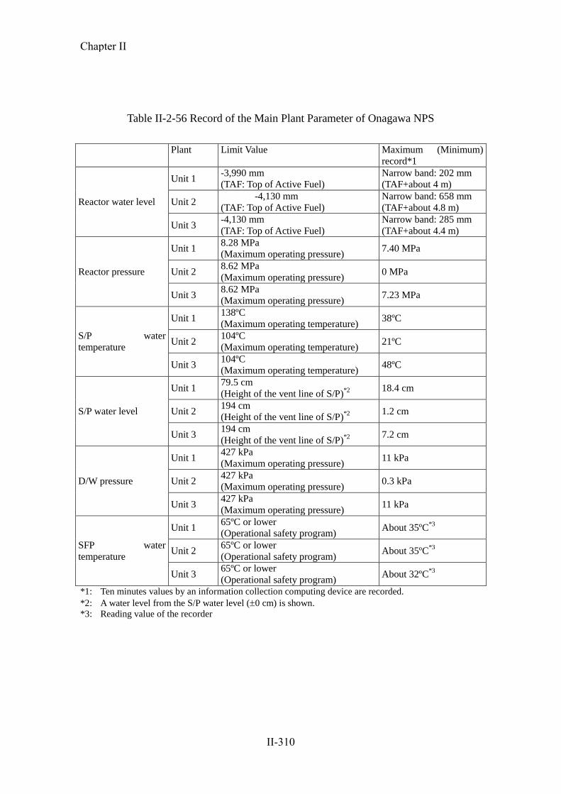
Table II-2-56 Record of the Main Plant Parameter of Onagawa NPS
Plant Limit Value Maximum (Minimum)
record*1
Reactor water level
Unit 1 -3,990 mm
(TAF: Top of Active Fuel)
Narrow band: 202 mm
(TAF+about 4 m)
Unit 2 -4,130 mm
(TAF: Top of Active Fuel)
Narrow band: 658 mm
(TAF+about 4.8 m)
Unit 3 -4,130 mm
(TAF: Top of Active Fuel)
Narrow band: 285 mm
(TAF+about 4.4 m)
Reactor pressure
Unit 1 8.28 MPa
(Maximum operating pressure) 7.40 MPa
Unit 2 8.62 MPa
(Maximum operating pressure) 0 MPa
Unit 3 8.62 MPa
(Maximum operating pressure) 7.23 MPa
S/P water
temperature
Unit 1 138ºC
(Maximum operating temperature) 38ºC
Unit 2 104ºC
(Maximum operating temperature) 21ºC
Unit 3 104ºC
(Maximum operating temperature) 48ºC
S/P water level
Unit 1 79.5 cm
(Height of the vent line of S/P)*2
18.4 cm
Unit 2 194 cm
(Height of the vent line of S/P)*2
1.2 cm
Unit 3 194 cm
(Height of the vent line of S/P)*2
7.2 cm
D/W pressure
Unit 1 427 kPa
(Maximum operating pressure) 11 kPa
Unit 2 427 kPa
(Maximum operating pressure) 0.3 kPa
Unit 3 427 kPa
(Maximum operating pressure) 11 kPa
SFP water
temperature
Unit 1 65ºC or lower
(Operational safety program) About 35ºC
*3
Unit 2 65ºC or lower
(Operational safety program) About 35ºC
*3
Unit 3 65ºC or lower
(Operational safety program) About 32ºC
*3
*1: Ten minutes values by an information collection computing device are recorded.
*2: A water level from the S/P water level (0 cm) is shown.
*3: Reading value of the recorder
Chapter II
II-310

Fig. II-2-133 Changes in Major Parameters at Unit 1 (from March 11 to March 12) (Report 1)
女川1号機 地震発生前後のプラントパラメータ
-5000
-4000
-3000
-2000
-1000
0
1000
2000
3/1112:00
3/1114:00
3/1116:00
3/1118:00
3/1120:00
3/1122:00
3/120:00
3/122:00
3/124:00
3/126:00
3/128:00
3/1210:00
3/1212:00
日時
原子
炉水
位(狭
帯域
)(m
m)/
発電
機出
力(M
W)
-1
0
1
2
3
4
5
6
7
8
原子
炉圧
力(M
Pa)
原子炉水位(狭帯域)(mm)左軸発電機出力(MW)左軸原子炉圧力(MPa)右軸
3/12 0:58原子炉冷温停止
原子炉水位計オーバースケール
3/11 14:46原子炉自動停止
March 11, 14:46
Reactor automatic SCRAM
Reactor water level became out of the measuring range of the reactor water level meter
March 12, 00:58
Reactor became into a cold
shutdown condition
Reactor water level (narrow band) (mm) plotted on the left vertical axis
Generator output (MW) plotted on the left vertical axis
Ractor ressure (MPa) plotted on the right vertical axis
Rea
cto
r w
ater
lev
el (
nar
row
ban
d)
(mm
)/G
ener
ato
r o
utp
ut
Rea
cto
r p
ress
ure
(M
Pa)
Date
Chapter II
II-311

Fig. II-2-134 Changes in Major Parameters at Unit 1 (from March 11 to March 12) (Report 2)
女川1号機 地震発生前後のプラントパラメータ
-60
-30
0
30
60
3/1112:00
3/1114:00
3/1116:00
3/1118:00
3/1120:00
3/1122:00
3/120:00
3/122:00
3/124:00
3/126:00
3/128:00
3/1210:00
3/1212:00
日時
S/P
水温
(℃)/
S/P
水位
(cm
)
-4
-2
0
2
4
6
8
10
12
原子
炉圧
力(M
Pa)
/D/W
圧力
(kP
a)
S/P水温(℃)左軸S/P水位(cm)左軸原子炉圧力(MPa)右軸D/W圧力(kPa)右軸
3/11 14:46原子炉自動停止
3/12 0:58原子炉冷温停止
SRV開操作に伴い、D/W圧力は一時的に上昇March 11, 14:46
Reactor automatic SCRAM
March 12, 00:58
Nuclear reactor beacme
into a cold shutdwon
condition
D/W pressure increased temporarily as a result of the opening of the SRV
S/P water temperature (C) plotted on the left vertical axis
S/P
wat
er t
emp
erat
ure
(C
)/ S
/P w
ater
lev
el (
cm)
Rea
cto
r p
ress
ure
(M
Pa)
/ D
/W p
ress
ure
(k
Pa)
Date
S/P water level (cm) plotted on the left vertical axis
Reactorl pressure (MPa) plotted on the right vertical axis
D/W pressure (kPa) plotted on the right vertical axis
Chapter II
II-312

Fig. II-2-135 Changes in Major Parameters at Unit 1 (from March 11 to March 12) (Report 3)
女川1号機 地震発生前後のプラントパラメータ
0
5
10
15
20
25
30
35
40
3/1112:00
3/1114:00
3/1116:00
3/1118:00
3/1120:00
3/1122:00
3/120:00
3/122:00
3/124:00
3/126:00
3/128:00
3/1210:00
3/1212:00
日時
使用
済燃
料プ
ール
水温
度(℃
)
使用済燃料プール水温度(℃)3/11 14:46原子炉自動停止
3/12 0:58原子炉冷温停止
March 11, 14:46
Reactor automatic SCRAM
March 12, 00:58
Reactor became into a cold
shutdown condition
Spent fuel pool water temperature (C)
Sp
ent
fuel
pool
wat
er t
emp
erat
ure
(C
)
Date
Chapter II
II-313

Fig. II-2-136 Changes in Major Parameters at Unit 2 (from March 11 to March 12) (Report 1)
女川2号機 地震発生前後のプラントパラメータ
-5000
-4000
-3000
-2000
-1000
0
1000
2000
3/1112:00
3/1114:00
3/1116:00
3/1118:00
3/1120:00
3/1122:00
3/120:00
3/122:00
3/124:00
3/126:00
3/128:00
3/1210:00
3/1212:00
日時
原子
炉水
位(狭
帯域
)(m
m)/
発電
機出
力(M
W)
-1
0
1
2
3
4
5
6
7
8
原子
炉圧
力(M
Pa)
原子炉水位(狭帯域)(mm)左軸発電機出力(MW)左軸原子炉圧力(MPa)右軸3/11 14:49
原子炉冷温停止
原子炉水位計オーバースケール
3/11 14:46原子炉自動停止
March 11, 14:46
Reactor automatic SCRAM
March 11, 14:49
Reactor became into a cold
shutdown condition
Date
Reactor water level became out of the measuring range of the reactor water level meter
Rea
cto
r w
ater
lev
el (
nar
row
ban
d)
(mm
)/G
ener
ato
r o
utp
ut
Rea
cto
r p
ress
ure
(M
Pa)
Reactor water level (narrow band) (mm) plotted on the left
vertical axis Generator output (MW) plotted on the left vertical axis
Reactor pressure (MPa) plotted on the right vertical axis
Chapter II
II-314

女川2号機 地震発生前後のプラントパラメータ
-60
-30
0
30
60
3/1112:00
3/1114:00
3/1116:00
3/1118:00
3/1120:00
3/1122:00
3/120:00
3/122:00
3/124:00
3/126:00
3/128:00
3/1210:00
3/1212:00
日時
S/P
水温
(℃)/
S/P
水位
(cm
)
-4
-2
0
2
4
6
8
10
12
原子
炉圧
力(M
Pa)
/D/W
圧力
(kP
a)
S/P水温(℃)左軸S/P水位(cm)左軸原子炉圧力(MPa)右軸D/W圧力(kPa)右軸
3/11 14:49原子炉冷温停止
3/11 14:46原子炉自動停止
Fig. II-2-137 Changes in Major Parameters at Unit 2 (from March 11 to March 12) (Report 2)
S/P
wat
er t
emp
erat
ure
(C
)/ S
/P w
ater
lev
el (
cm)
March 11, 14:46
Reactor automatic SCRAM
March 11, 14:49
Reactor became into a cold
shutdown condition
S/P water temperature (C) plotted on the left vertical axis S/P water level (cm) plotted on the left vertical axis
Reactor pressure (MPa) plotted on the right vertical axis
D/W pressure (kPa) plotted on the right vertical axis
Rea
cto
r p
ress
ure
(M
Pa)
/ D
/W p
ress
ure
(k
Pa)
Date Chapter II
II-315

女川2号機 地震発生前後のプラントパラメータ
0
5
10
15
20
25
30
35
40
3/1112:00
3/1114:00
3/1116:00
3/1118:00
3/1120:00
3/1122:00
3/120:00
3/122:00
3/124:00
3/126:00
3/128:00
3/1210:00
3/1212:00
日時
使用
済燃
料プ
ール
水温
度(℃
)
使用済燃料プール水温度(℃)3/11 14:49原子炉冷温停止
3/11 14:46原子炉自動停止
Fig. II-2-138 Changes in Major Parameters at Unit 2 (from March 11 to March 12) (Report 3)
March 11, 14:49
Reactor became into a cold
shutdown condition
March 11, 14:46
Reactor automatic SCRAM
Spent fuel pool water temperature (C)
Date
Sp
ent
fuel
poo
l w
ater
tem
per
atu
re (C
)
Chapter II
II-316

Fig. II-2-139 Changes in Major Parameters at Unit 3 (from March 11 to March 12) (Report 1)
女川3号機 地震発生前後のプラントパラメータ
-5000
-4000
-3000
-2000
-1000
0
1000
2000
3/1112:00
3/1114:00
3/1116:00
3/1118:00
3/1120:00
3/1122:00
3/120:00
3/122:00
3/124:00
3/126:00
3/128:00
3/1210:00
3/1212:00
日時
原子
炉水
位(狭
帯域
)(m
m)/
発電
機出
力(M
W)
-1
0
1
2
3
4
5
6
7
8
原子
炉圧
力(M
Pa)原子炉水位(狭帯域)(mm)左軸
発電機出力(MW)左軸原子炉圧力(MPa)右軸
3/12 1:17原子炉冷温停止
原子炉水位計オーバースケール
3/11 14:46原子炉自動停止
Rea
cto
r w
ater
lev
el (
nar
row
ban
d)
(mm
)/G
ener
ato
r o
utp
ut
March 11, 14:46
Reactor automatic SCRAM
March 12,1:17
Reactor became into a cold
shutdown condition
Rea
cto
r p
ress
ure
(M
Pa)
Reactor water level became out of the measuring range
of the reactor water level meter
Date
Reactor water level (narrow band) (mm) plotted on the left
vertical axis Generator output (MW) plotted on the left vertical axis
Reactor pressure (MPa) plotted on the right vertical axis
Chapter II
II-317

Fig. II-2-140 Changes in Major Parameters at Unit 3 (from March 11 to March 12) (Report 2)
女川3号機 地震発生前後のプラントパラメータ
-60
-30
0
30
60
3/1112:00
3/1114:00
3/1116:00
3/1118:00
3/1120:00
3/1122:00
3/120:00
3/122:00
3/124:00
3/126:00
3/128:00
3/1210:00
3/1212:00
日時
S/P
水温
(℃)/
S/P
水位
(cm
)
-4
-2
0
2
4
6
8
10
12
原子
炉圧
力(M
Pa)
/D/W
圧力
(kP
a)
S/P水温(℃)左軸S/P水位(cm)左軸原子炉圧力(MPa)右軸D/W圧力(kPa)右軸
3/12 1:17原子炉冷温停止
3/11 14:46原子炉自動停止
SRV開操作に伴い、D/W圧力は一時的に上昇
S/P
wat
er t
emp
erat
ure
(C
)/ S
/P w
ater
lev
el (
cm)
March 11, 14:46
Reactor automatic SCAM
March 12, 1:17
Reactor became into a cold
shutdown condition
Date
D/W pressure increased temporarily as a result of the opening of the SRV
Rea
cto
r p
ress
ure
(M
Pa)
/ D
/W p
ress
ure
(k
Pa)
S/P water temperature (C) plotted on the left vertical axis S/P water level (cm) plotted on the left vertical axis
Reactor pressure (MPa) plotted on the right vertical axis
D/W pressure (kPa) plotted on the right vertical axis
Chapter II
II-318

女川3号機 地震発生前後のプラントパラメータ
0
5
10
15
20
25
30
35
40
3/1112:00
3/1114:00
3/1116:00
3/1118:00
3/1120:00
3/1122:00
3/120:00
3/122:00
3/124:00
3/126:00
3/128:00
3/1210:00
3/1212:00
日時
使用
済燃
料プ
ール
水温
度(℃
)
使用済燃料プール水温度(℃)
3/12 1:17原子炉冷温停止
3/11 14:46原子炉自動停止
Fig. II-2-141 Changes in Major Parameters at Unit 3 (from March 11 to 12) (Report 3)
Sp
ent
fuel
poo
l w
ater
tem
per
atu
re (C
)
March 11, 14:46
Reactor automatic SCRAM March 12, 1:17
Reactor became into a cold
shutdown condition
Spent fuel pool water temperature (C)
Date
Chapter II
II-319

g. Impact of radioactive materials to outside
○ Status of fuel in reactors and spent fuel
Water levels inside the reactors were kept higher than the top of active
fuel from the time of the earthquake to cold shutdown. Sufficient water
levels were also secured in the spent fuel pools. Measurement results of the
reactor water and the water in the spent fuel pools are indicated in Table
II-2-57.
The concentration of iodine-131 in the reactor water of both Units 1 and
2 showed no significant change compared with the concentration before
the earthquake, and thus has not indicated a probability of damage to fuel.
Based on that, damage to fuel caused by the earthquake is not estimated to
have occurred.
For Unit 3, since December 27, 2010 before the earthquake, there was
indication of a small amount of radioactive materials that had leaked from
part of a fuel rod in the reactor. Therefore, control rods around the fuel
having the potentiality of leakage had been inserted to control the leak of
the radioactive materials. Measured concentrations of iodine during the
time between the incidence of fuel damage and the earthquake fluctuated
in the range of (0.00985 to 0.0195Bq/g). Concentrations of iodine before
and after the earthquake were within this same range of fluctuation and
were at less than one-thousandth of the limit defined by the
Fitness-for-Safety Program (1.8×10³(Bq/g), suggesting sufficiently low
values. Further, also for the spent fuel pool, concentration measurements of
cesium-137 showed no significant change since the time before the
earthquake, and thus have not indicated the probability of damage to fuel.
Based on that, damage to the fuel by the earthquake is not estimated to
have occurred.
○ Situation of monitoring posts, etc.
As measurements taken by the monitoring post (MP) started to rise at
around 23:00 on March 12, reaching a maximum of 21 μSv/h (MP2) at
01:50 on March 13, notification pursuant to Article 10 of the Act on
Special Measures Concerning Nuclear Emergency Preparedness
(hereinafter referred to as Article 10 of the Nuclear Emergency
Preparedness Act) was submitted at 12:50 on March 13. After that, the
MP measurement continued to decrease, going below the notification
Chapter II
II-320

standard value of 5μSv/h at 23:20 on March 15, and the first emergency
response pursuant to Article 10 of the Nuclear Emergency Preparedness
was lifted on June 13, 2011.
The rise of the MP measurement is estimated to be due to the effects of
the release of radioactive materials caused by the accident at the
Fukushima Dai-ichi NPS. The reasons are as follows.
・ For Units 1 to 3, the plants were not in operation after the cold
shutdown, and, at the time of the notification pursuant to Article 10 of
the Nuclear Emergency Preparedness, the plant parameters showed no
change and remained stable.
・ Although the MP measurement rose at around 23:00 on March 12, the
reading of the stack radiation monitor rose at around 0:00 on March
13, suggesting that the MP measurement rose ahead of the reading.
・ Readings taken by the stack radiation monitor ranged from 44 to 47
cps (at around 01:50 on March 13) and were sufficiently below the
value (equivalent to 1,650 cps), which the notification standard value
(5 μSv/h) converts to for readings taken by the stack radiation
monitor.
MP measurements associated with the notification pursuant to Article 10
of the Nuclear Emergency Preparedness are indicated in Figure II-2-142.
○ Release of radioactive materials to the outside
Due to the earthquake, a minor leak of radioactive material caused by
sloshing of the spent fuel pool water, water leaks in buildings, etc. was
observed, but all remained inside of the buildings and no effects of
radioactive materials upon the outside were found.
Chapter II
II-321

Table II-2-57 Results of Measurement of the Concentrations of Iodine 131 in Reactor
Water and of Cesium 137 in Spent Fuel Pool Water
(Bq/g)
Iodine 131 in reactor water Cesium 137 in spent fuel pool
water
Before the
earthquake
After the
earthquake
Before the
earthquake
After the
earthquake
Unit 1
(Date of
sampling)
0.0161
(March 7)
0.0171
(March 18)
Less than
0.013*
(March 7)
Less than
0.0406*
(March 14)
Unit 2
(Date of
sampling)
Less than
0.00141*
(March 8)
0.00873
(March 18)
Less than
0.0211*
(February 8)
Less than
0.0341*
(April 19)
Unit 3
(Date of
sampling)
0.00985
(March 11)
0.0199
(March 15)
Less than
0.0076*
(March 9)
Less than
0.0132*
(March 14)
* Less than the detection limit
Chapter II
II-322

0.01
0.10
1.00
10.00
100.00
1000.00
3/11 3/14 3/17 3/20 3/23 3/26 3/29 4/1
線量
率(μ
Sv/h)
図7 MP 配置図,測定データ
6/1 6/4 6/7 6/10 6/133/11 3/14 3/17 3/20 3/23 3/26 3/29 6/4 6/7 6/10 6/13
Dose
ra
te (μ
Sv/h
)
Onagawa Nuclear Power Station Monitoring Post Data
Fig. II-2-142 Measurements at Monitoring Posts in Accordance with Article 10 of Act on Special Measures Concerning
Nuclear Emergency Preparedness
March 13, 13:30
21 μSv/h at MP-2
June 13, 15:00
0.21 μSv/h at MP-2
March 15, 23:20
The dose rate lower than the reportable reference value of
5 μSv/h was observed at MP-2
[Measurements (μSv/h) at MPs around 24:00 on August 31]
MP-1:0.10 MP-2:0.13 MP-3:0.09 MP-4:0.09 MP-5:0.10 MP-6:0.11
MP-1
MP-2
MP-3
MP-4
MP-5
MP-6
Chapter II
II-323

h. Loss of functions of the RCW (B) system, RSW (B) system, and HPCW of Unit 2
due to the tsunami
RCW (B), RSW (B) and HPCW were submerged due to tsunami, and RHR (B),
HPCS, emergency DG (B) and DG (H) became unavailable as detailed below.
○Summary
At 14:47, following the automatic reactor shutdown, emergency DGs (A),
(B) and (H) automatically started up (no-load operation). However, after
RCW (B) automatically shut down at 15:34, backup RCW (D) started up and
shut down immediately, and as a result, emergency DG (B) lost its supply of
coolant and automatically shut down at 15:35.
Also, at 15:41, the HPCW pump automatically stopped, and as a result, DG
(H) lost its supply of coolant and automatically shut down at 15:42.
Through an on-the-spot check, seawater intrusion was confirmed in the
RCW heat exchanger (B) room, the HPCW heat exchanger room, and in the
stair hall leading to the elevator area located in non-controlled areas in the
third basement of the reactor building (hereinafter referred to as ―the relevant
area‖), and the immersion of RCW pumps (B) and (D) as well as HPCW
pump was also confirmed.
In addition, patrols confirmed flooding in the RSW pump (B) region in the
seawater pump room outside the reactor building as well as possible
submersion of RSW pumps (B) and (D) located in the region.
The depth of water was confirmed to have been 2.5m, based on traces
found in the relevant area.
Figure II-2-143 shows the immersion/submersion that occurred in the
relevant area.
Seawater inflow was also found in the RCW heat exchanger (A) room, but
with a water depth of approximately 0.5m, RCW (A) was not affected.
Chapter II
II-324

○Presumed cause
When the additional water-level detector for automatic shutdown of the
recirculation pump (hereinafter referred to as ―the relevant water-level
detector‖) in RSW pump (B) region in the Seawater Pump Room as a
countermeasure for tsunami backwash was installed (in 2002), consideration
to the effects of a tsunami spilling wave and water-shutoff measures were
insufficient when selecting the location of the detector.
It is presumed that tsunami seawater has flowed into the seawater pump
room from the seawater intake channel through the installation box of the
relevant water-level detector after the earthquake, that the RSW pump (B)
region was flooded, and that seawater flowed into a part of the reactor
building through the underground trench, and that as a result, RCW (B),
RSW (B), and HPCW functions were lost.
Although the same water-level detectors are installed at Unit 1 and Unit 3,
they are located in different regions (located in the Dust Arrester Rooms) so
that the RCW systems and other safety equipment were not affected by
tsunami.
Figure II-2-144 shows the presumed mechanism of seawater
immersion/flooding.
Figure II-2-145 shows the installation conditions of the relevant water-level
detector.
○ Countermeasures
Submerged pump motors and MO valve drives were disassembled,
examined, repaired, and recovered.
- The relevant water-level detector was dismantled, and the openings that
had allowed tsunami seawater inflow were waterproofed.
The relevant water-level detector will be relocated in consideration of
Chapter II
II-325

preventing seawater inflow.
- Repair work has been undertaken on penetrations for pipes and cable
trays from the seawater pump room to the trench.
- In the future, the water-tightness of building doors will be improved and
tide embankments/barriers will be constructed.
Chapter II
II-326

-
-
-
-
-
-
-
-
-
-
-
-
-
-
-
-
-
-
-
-
-
-
-
-
-
-
-
-
-
-
-
- Fig. II-2-143 Seawater flooding condition
RCW pump (B) (after seawater was drained)
HPCW pump (after seawater was drained)
Seawater flooding in the RCW heat
exchanger chamber B
Seawater flooding in the HPCW heat
exchanger chamber
Inundation height of
seawater
Inundation height
of seawater
Chapter II
II-327

-
- Fig. II-2-144 Estimated mechanism of flooding
Controlled area
The inundation pathway is estimated as follows from the on-site investigation:
(1) Due to tide rise caused by the tsunami that followed the earthquake, the container upper cover of the water gauge for
automatic shutdown of the circulation water pump, which was installed on the floor of RSW pump (B) area in the seawater
pump room, opened to allow seawater to overflow into RSW pump (B) area.
(Water inflow to RSW system-(B) pump area in the seawater pump room)
(2) Seawater that had flown into RSW pump (B) area entered the RSW (B) piping trench through the cable tray penetrations and
the piping penetrations. (Water inflow to RSW (B) trench piping)
(3) Seawater that had flown into RSW (B) piping trench entered RCW heat exchanger (B) room through the piping penetrations
and the seawater storm drain transfer-system sump.
(Water inflow to RCB heat exchanger (B) room; inundation of RCW pumps (B) and (D))
(4) Seawater that had flown into RCW heat exchanger (B) room leaked through the watertight door to flow into HPCW heat
exchanger room.
(Water inflow to HPCW heat exchanger room; inundation of HPCW pump)
(8) Seawater that had flown into HPCW heat exchanger room
entered RCW heat exchanger room (A) along power
cables.
(Water inflow to RCW heat exchanger room (A);
no impact on RCW pumps (A) and (C))
(5) Seawater that had flown into HPCW heat
exchanger room leaked through the watertight
door to flood the elevator area.
(Inundation of the elevator area)
(6) Seawater that had flown into HPCW heat exchanger
room flew into HPSW piping trench through the
seawater storm drain transfer-system sump.
(Water inflow to HPSW piping trench)
(7) Seawater that had flown into HPSW piping trench
leaked through the watertight door to flow into RSW
(A) piping trench.
(Water inflow to RSW (A) piping trench)
(9) Seawater that had flown into RSW (A) piping trench
flew into RCW heat exchanger room (A) through the
seawater storm drain transfer-system sump.
(Water inflow to RCW heat exchanger room (A);
no impact on RCW pumps (A) and (C))
Legend of abbreviations:
ECWS: Emergency component cooling seawater system
HPCW: High pressure core spray component cooling water
system
HPCS: High pressure core spray system
HPSW: High pressure core spray component cooling seawater
system
Hx: Heat exchanger
RCW: Reactor component cooling water system
RHRS: Residual heat removal seawater system
RSW: Reactor component cooling seawater system
SWSD: Seawater storm drain transfer system
TSW: Turbine component cooling seawater system
Note: O.P. values in this figure do not reflect crustal movements after the earthquake.
Inlet to the seawater pump room
(Water gauge for automatic shutdown installed
in circulation water pump room)
RCW heat exchanger room (A) (Inundation level: Approx. 0.5 m h)
RC
W
pum
p
RC
W h
eat
exch
anger
Sta
irs
Non-controlled area
RCW heat exchanger room (B)
(Inundation level: Approx. 2.5 m)
RCW pump
Sta
irs
HPCW pump
RCW heat exchanger HPCW heat exchanger (Inundation level Approx. 2.5 m )
HPCW heat exchanger
Stairs
RSW (A) trench TSW trench
HP
SW
tre
nch
RS
W (
B)
tren
ch Legend:
Trench cross section
Cross section of seawater pump
room R/B cross section
HPSW pump
RSW system-A
pump
RSW system-B
pump
RSW system-A piping
HPSW system piping
RSW system-B piping
Elevator room
HPCW Hx room
RCW
Hx (B)
room
Trench height: OP 3000
Trench height: OP 6350
Trench height: OP 8850
No
rmal
tid
e le
vel
Intake
channel
RSW (B) rout trench Water flow into HPSW piping trench
Plane view (trenches and R/B viewed from above)
RCW Hx (B) room
Elevator room
TSW (B) rout trench
TSW rout trench
HPSW rout trench
RSW (A) rout trench
RCW Hx (A) room
HPCW Hx
room
Elevator room (Inundation level: Approx. 2.5
m )
Water inflow through piping penetrations
Water inflow through
SWSD Water inflow along power cables
Water inflow through watertight doors
SWSD
Inundated area (loss of function) Inundated area (no impact on facilities)
Chapter II
II-328
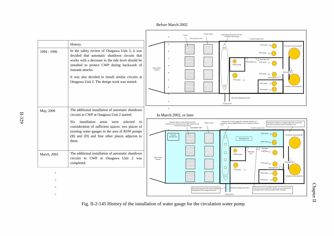
-
-
-
-
-
-
-
-
-
-
-
-
-
-
-
-
-
-
-
-
-
-
-
-
History
1994 - 1996 In the safety review of Onagawa Unit 3, it was
decided that automatic shutdown circuits that
works with a decrease in the tide level should be
installed to protect CWP during backwash of
tsunami attacks.
It was also decided to install similar circuits at
Onagawa Unit 2. The design work was started.
May, 2000 The additional installation of automatic shutdown
circuits to CWP at Onagawa Unit 2 started.
Six installation areas were selected in
consideration of sufficient spaces: two places of
existing water gauges in the area of RSW pumps
(B) and (D) and four other places adjacent to
them.
March, 2002 The additional installation of automatic shutdown
circuits to CWP at Onagawa Unit 2 was
completed.
Fig. II-2-145 History of the installation of water gauge for the circulation water pump
Before March 2002
In March 2002, or later
循環水ポンプ水位計貫通部
循環水ポンプ(A)
循環水ポンプ(B)
水密扉
TSWポンプ(A)
HPSWポンプ
TSWポンプ(B)
TSWポンプ(C)
RSWポンプ(A)
RSWポンプ(C)
RSWポンプ(D)
RSWポンプ(B)
取水路
除塵装置室 海水ポンプ室
バケットスクリーンスクリーン
RSW(B)地下トレンチ
原子炉建屋へ
水密扉
水密扉
水密扉
水没エリア
循環水ポンプ自動停止用水位計貫通部(H14.3設置完了)
循環水ポンプ(A)
循環水ポンプ(B)
水密扉
TSWポンプ(A)
HPSWポンプ
TSWポンプ(B)
TSWポンプ(C)
RSWポンプ(A)
RSWポンプ(C)
RSWポンプ(D)
RSWポンプ(B)
取水路
除塵装置室 海水ポンプ室
RSW(A)(C)エリアとRSW(B)(D)エリアは水密扉付きの壁で仕切られているため,浸水が拡大しなかった
バケットスクリーンスクリーン設置跡
(A系H13.7撤去、B系H15.1撤去)溢水、火災等により同時に機能喪失することのないよう非常用設備は独立した配置
RSW(B)地下トレンチ
原子炉建屋へ
海水流入エリア
RSW(B)地下トレンチを経由し、原子炉建屋の一部へ流入
水密扉
水密扉
水密扉
Screen Bucket screen
Water gauge penetrations for the circulation water pump
Dust extractor room Seawater pump room
RSW pump Circulation water pump (B)
Water intake
channel
RSW (B) underground trench
To the reactor
building
TSW pump
HPSW pump
RSW pump
TSW pump Watertight door
Remains where screens had been placed
(System A was removed in July 2001; System B was removed in January 2003)
Penetrations of water gauge for automatic shutdown of
circulation water pump(Installation was completed in March
2002)
Seawater pump room
Emergency facilities are aligned separately so that they
may not lose functions due to flooding or fire.
Seawater
flooded area Submerged area
RSW pump
RSW pump
Water flew into part of the reactor building through RSW (B) underground trench.
RSW (A) (C) areas and RSW (B) (D) areas are separated by watertight doors, which prevented further flooding.
Watertight door
Watertight door
Circulation water pump (A)
TSW pump
RSW pump
RSW pump
Dust extractor room
Bucket screen
Water intake
channel
HPSW pump
TSW pump
Watertight
door
Watertight
door TSW pump
TSW pump
Watertight door
Watertight door
Watertight door
RSW pump
RSW pump
Circulation water pump (B)
Circulation water pump (A)
RSW (B) underground trench
To the reactor
building
Chapter II
II-329
i. Fire in the high-voltage power panel at Unit 1
Due to the fire in the high-voltage power panel on normal system caused by the
earthquake, the power supply to the emergency power unit from an external source
became unavailable, and an emergency power supply was made via emergency DGs.
Details of this incident are as described below.
○ Outlines
After the earthquake, a fire alarm went off in the main control room at
14:57, whereupon operators headed to the site and confirmed smoke
originating from the basement of the turbine building at 15:30.
Along with calling 119 to report the fire, a fire fighting team from the
in-house fire brigade headed to the site to extinguish the fire, but the team
could not locate the source of the smoke due to poor visibility in the smoke.
Therefore, considering the possibility of an oil fire, a fire extinguishing
operation using a carbon dioxide fire extinguishing unit was started in the
main oil tank room in the second basement of the turbine building at 17:15
on the same day.
Afterwards, it was confirmed that there had been burnout and smoke
generation from units No. 7 and No. 8 (hereinafter referred to as ―the
relevant units‖) of the high-voltage power panels 6-1A (hereinafter referred
to as "the relevant panels") on the normal system, i.e. the high-voltage power
panels in the first basement of the turbine building. Because the internals of
the relevant units were still overheated, dry-chemical extinguishers were
used.
Because some parts of the access roads to the power plant had been
damaged by the earthquake and tsunami, it was difficult for firefighters to
reach the plant, so a subcontractor worker who used to work for the fire
department confirmed extinction at 22:55.
Due to this incident, at 14:55, the start-up transformer that had been
receiving off-site power stopped operating, as overcurrent relay was
activated. Nevertheless, both emergency DG (A) and (B) operated properly,
Chapter II
II-330

and power was supplied to on-site emergency facilities.
In addition, visual external inspection and insulation resistance
measurements confirmed no abnormalities in the start-up transformer, so that
the transformer was restored at 2:05 on March 12, and normal buses other
than those of the relevant panels were also restored subsequently.
Figure II-2-146 shows the power supply system before and after the
earthquake.
○ Presumed cause
It is presumed that a magnetic blast circuit breaker (MBB) suspended at
the connecting point on the relevant panel was largely shaken by the
earthquake, breaker paths on both the panel and the MBB sides were
damaged, connecting conductors contacted with peripheral structures
causing short circuits and ground-faults, heat was generated by arcing, and
the insulation coating of cables in the panel melted down and generated
smoke.
Figure II-2-147 shows the presumed mechanism of fire outbreak in the
relevant units.
○ Countermeasures
For the relevant high-voltage power panel or the same type of panels of
the normal system, conventional vertical-type MBBs will be replaced by
horizontal-type vacuum circuit breakers that have a higher quake resistance.
Figure II-2-148 shows a vacuum circuit breaker (schematics).
Chapter II
II-331
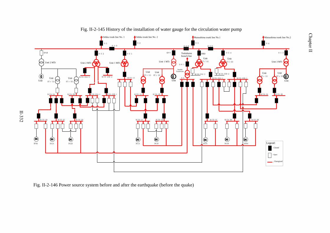
GG
M/C6-2A
M/C6-2H M/C6-2C
M/C6-2B
M/C6-2D
M/C6-2SA-2 M/C6-2SB-2
M/C6-2SA-1 M/C6-2SB-1
G
M/C6-1A M/C6-1B
M/C6-1S
M/C6-1C M/C6-1D
M/C6-3A M/C6-3B
6-E M/C6-3SB-1
M/C6-3SB-2M/C6-3SA-2
M/C6-3SA-1
M/C6-3C M/C6-3D M/C6-3H
010 020 030
04
松島幹線2号
03
松島幹線1号
01
牡鹿幹線1号
02
牡鹿幹線2号
052O12 051 O11 O53 054 013
2号MTr
2号
2号STr 1号STr
2号HTr(A)
2号HTr(B)
1号HTr(A)
1号HTr(B)
1号
1号MTr
3号STr(A)
3号STr(B)
3号HTr(B)
3号HTr(A)
3号
3号MTr
HPDG DG2A DG2B DG1A DG1B DG3A DG3B HPDG
予備変圧器
塚浜支線
061
DG DG DG DG DG DG DG DG
凡例
:投入
:開放
:充電
Fig. II-2-146 Power source system before and after the earthquake (before the quake)
Fig. II-2-145 History of the installation of water gauge for the circulation water pump
Oshika trunk line No. 1 Matsushima trunk line No.1
Legend:
: Closed
: Open
: Energized
Oshika trunk line No. 2 Matsushima trunk line No.2
Unit 2 MTr Unit 2 MTr Unit 1 MTr Unit 1 MTr
Tsukahama
branch line Unit
3 Unit
3
Standby
Transformer
Unit
2
Unit
2
Unit
2
Unit
1 Unit
1
Unit
1
Unit
3
Unit
3
Unit
3
Unit 3 MTr
Chapter II
II-332

G
凡例
G
M/C6-2A
M/C6-2H M/C6-2C
M/C6-2B
M/C6-2D
M/C6-2SA-2 M/C6-2SB-2
M/C6-2SA-1 M/C6-2SB-1
G
M/C6-1A M/C6-1B
M/C6-1S
M/C6-1C M/C6-1D
M/C6-3A M/C6-3B
6-E M/C6-3SB-1
M/C6-3SB-2M/C6-3SA-2
M/C6-3SA-1
M/C6-3C M/C6-3D M/C6-3H
010 020 030
04
松島幹線2号
03
松島幹線1号
01
牡鹿幹線1号
02
牡鹿幹線2号
052O12 051 O11 O53 054 013
2号MTr
2号
2号STr 1号STr
2号HTr(A)
2号HTr(B)
1号HTr(A)
1号HTr(B)
1号
1号MTr
3号STr(A)
3号STr(B)
3号HTr(B)
3号HTr(A)
3号
3号MTr
HPDG DG2A DG2B DG1A DG1B DG3A DG3B HPDG
予備変圧器
塚浜支線
061
:投入
:開放
DG DG DG DG DG DG DGDG
14:46短絡/地絡によりトリップ 14:46短絡/地絡によりトリップ
14:55過電流によりトリップ
14:46短絡/地絡によりトリップ
短絡/地絡発生M/C
6-1A焼損
14:46 DG(A),DG(B),DG(H)自動起動15:35 RCWポンプ冠水のためDG(B)自動停止15:42 HPCWポンプ冠水のためDG(B)自動停止
14:47 DG(A),DG(B)自動起動14:55 DG(A),DG(B)負荷運転開始
:充電
Fig. II-2-146 Power source system before and after the earthquake (after the quake)
At 14:47: DG (A) and DG (B) automatically started.
At 14:55: DG (A) and DG (B) started load operation. At 14:46: DG (A), DG (B), and DG (H) automatically started
At 15:35: DG (B) automatically shut down because RCW pump
was submerged. At 15:42: DG (H) automatically shut down because HPCW pump
was submerged.
M/C 6-1A burned
out due to short
circuit/earth fault
Tripped at 14:55 due to overcurrent
Tripped at 14:46 due to short circuit/earth fault
Oshika trunk line No. 1
Tripped at 14:46 due to short circuit/earth fault Tripped at 14:46 due to short circuit/earth fault
Oshika trunk line No. 2 Matsushima trunk line No.1 Matsushima trunk line No.2
Legend:
: Closed
: Open
: Energized
Unit 2 MTr Unit 2 MTr
Unit
2
Standby
Transformer
Tsukahama
branch line
Unit 1 MTr Unit 1 MTr
Unit
3
Unit
3
Unit
1
Unit
2
Unit
2
Unit
1
Unit
1 Unit
3
Unit
3
Unit
3
Unit 3 MTr
Chapter II
II-333

←前方 後方→
マグネブラスト遮断器(MBB)
変流器
母線
断路部
一次側
断路部
二次側
制御ダクト
母線
MBB昇降装置
マグネブラストしゃ断器(MBB)
バリア
MBBを前方から見るMBBを前方から見る
【メタクラ側面図】 【メタクラ正面図】
【火災発生に至る推定メカニズム】
運転中の接続位置の当該ユニットは、縦型のマグネブラストしゃ断器(MBB)であることから、断路位置から接続位置にする際には、MBBを昇降装置で吊り上げることになるが、MBB下部に耐震架台を設置していないため固定されていない。 このため、接続位置のMBB下部には30cm程度のスペースが生じることとなるが、地震による大きな振動が加わるとMBBは大きく揺れ、断路部またはしゃ断器内部が変形・破損する可能性がある。 また、調査結果より当該ユニット内のMBB上部に位置する断路部付近が著しく損傷しており、中央制御室においても短絡および地絡に関係する警報が発報されていたことが確認されていることから、当該ユニット内部でアーク放電が発生していた可能性が高い。 よって、以下のメカニズムにより火災に至ったものと推定される。
①耐震架台がなく,下部スペース(30cm程度吊り上げ)があるMBBは固定されないため、地震による大きな振動で大きく揺れ、断路部が破損する
②接続導体と周辺の構造物(バリアなど)が接触し地絡・短絡が発生する
③内部短絡によりアーク放電が発生する
④アーク放電の熱によりケーブル絶縁被覆から発煙、しゃ断器焼損(火災に至る)
①地震の大きな振動によって、耐震架台が設置されていない当該盤のMBBは固定されず、下部にスペースがあること から大きく揺れ、一次、二次側断路部の接続導体および絶縁物が変形・破損した。
②断路部の変形・破損により接続導体が周囲の構造物(バリアなど)と接触し短絡・地絡が発生した。
③内部短絡により接続導体と周囲の構造物でアーク放電が発生した。
④アーク放電の発生熱の影響により、盤内ケーブルの絶縁被覆は溶けて発煙し、しゃ断器を含む周辺構造物が焼損した。
なお、火災発生箇所における火気使用および可燃物(ケーブル絶縁被覆は難燃性)は無く、確認された延焼跡も当該ユニットを中心していることからも電気設備以外の火災要因は極めて考え難い。(当日の自衛消防隊消火班の現場確認の際も炎は確認されていない状況である。)
30cm程度
Fig. II-2-147 Estimated mechanism of the fire
[Side view of the metal-clad switchgear] [Front view of the metal-clad switchgear]
Front Back
Controller duct
(2) Connecting conductors make contact with surrounding structures (such as barriers) leading to ground fault or
(3) Internal short circuit causes arc discharge.
(4) Heat generated by the arc discharge causes smoke from cable insulating sheath, and burns the breaker (leading to fire).
(1) Because MBB with a space underneath of it (lifted about 30 cm) and without a quake-resistant frame is not secured, large seismic motion makes it swing significantly, leading to damage on a disconnecting section.
Magnetic blast breaker (MBB)
Approximately 30 cm
Bus Barrier
Seco
ndar
y di
scon
nect
ing
sect
ion
Prim
ary
disc
onne
ctin
g se
ctio
n
Front view of MBB
MB
B li
fting
dev
ice
Bus
Current transforme
Estimated mechanism that led to the fire:
Because the breaker unit in connecting position during operation is a vertical-type magnet blast breaker (MBB), the lifting device lifts the MBB in order to shift its position from disconnection to connection. However, the MBB is not secured because no quake-resistant frame is installed under MBB.
This makes a space of about 30 cm under the MBB at its connecting position, and a large seismic motion can make the MBB swing significantly to deform or damage the disconnecting sections or the inside of the breaker.
The investigation revealed that the area close to the disconnecting section on top of MBB in this unit was significantly damaged, and that short circuit and ground fault alarms were set off in the Main Control Room. It is highly likely that arc discharge had occurred in this unit.
Therefore, the mechanism for the fire is estimated as follows:
(1) The MBB of this breaker unit with no quake-resistant frame was not secured. A large seismic motion made the MBB swing significantly due to the space under the MBB, and the connecting conductors and insulators at the primary and secondary disconnecting sections were deformed and damaged.
(2) Deformation and damage at the disconnecting sections caused connecting conductors to make contact with surrounding structures (such as barriers) leading to ground fault or short circuit.
(3) Internal short circuit caused arc discharge between the connecting conductors and the surrounding structures.
(4) Heat generated by the arc discharge caused the cable insulating sheath in the unit to melt to issue smoke, burning the surrounding structures including the breaker.
The cause of the fire cannot be other than the electric equipment, because fire was not used and no combustible material (the cable insulating sheath is flame retardant) was present at the place of the fire, and identified remains of fire spread were restricted to the area close to this unit. (The fire-fighting team of the In-house Fire Brigade did not recognize any flames at this site on the day of the fire.)
Chapter II
II-334
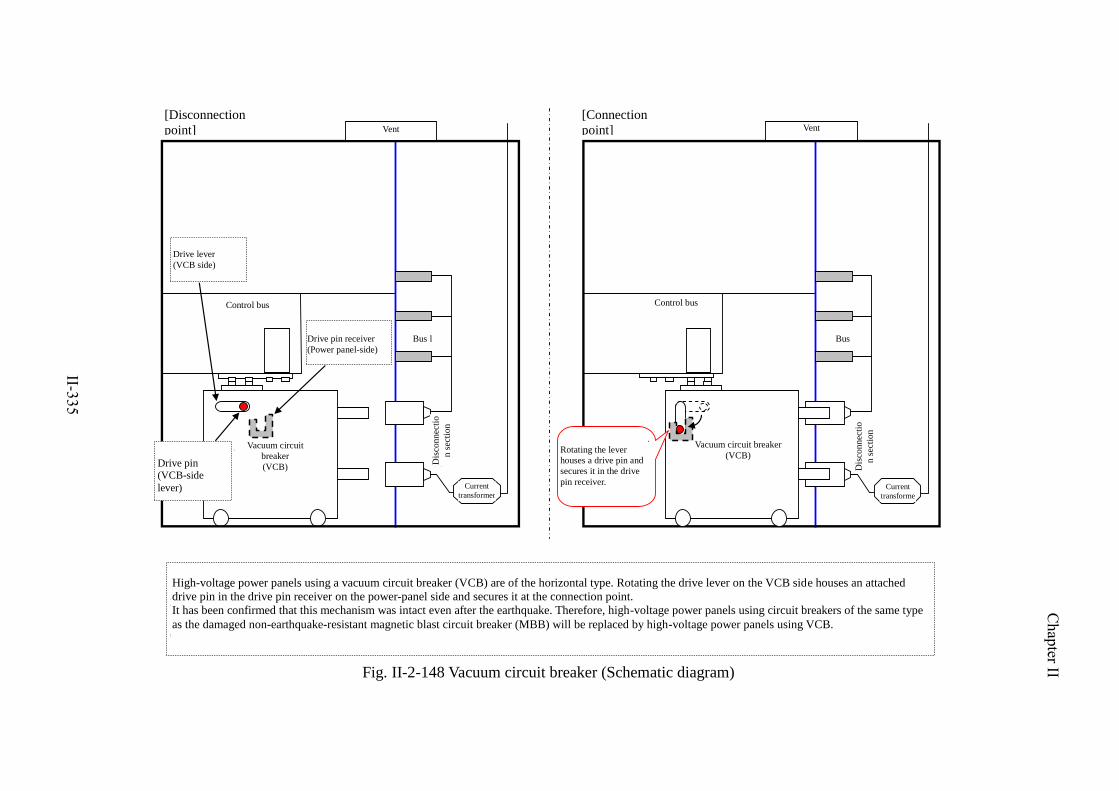
変流器
母線
断路部
真空しゃ断器(VCB)
制御母線
換気口
変流器
母線
断路部
制御母線
真空しゃ断器(VCB)
換気口
レバーを回転することで駆動ピンが受けに収まり固定される
【断路位置】 【接続位置】
真空しゃ断器(VCB)を使用している高圧電源盤は,横置き型であり,VCB側の駆動レバーを回転させることで付属の駆動ピンが電源盤側の駆動ピン受けに収まるため,接続位置に固定される機構となっている。 また,今回の地震の揺れに対しても健全であることが確認していることから,破損した非耐震型マグネブラストしゃ断器(MBB)と同型の高圧電源盤については,今後,VCBを使用する高圧電源盤に設備更新する。
駆動ピン受け(盤側)
駆動レバー(VCB側)
駆動ピン(VCB側レバー付属)
Fig. II-2-148 Vacuum circuit breaker (Schematic diagram)
[Disconnection
point]
[Connection
point] Vent Vent
Drive lever
(VCB side)
Drive pin receiver
(Power panel-side)
Control bus
Bus l
Control bus
Dis
con
nec
tio
n s
ecti
on
Vacuum circuit
breaker
(VCB)
Drive pin (VCB-side
lever)
Rotating the lever
houses a drive pin and
secures it in the drive
pin receiver.
Vacuum circuit breaker
(VCB)
Current
transformer
Bus
Dis
con
nec
tio
n s
ecti
on
Current
transforme
r
High-voltage power panels using a vacuum circuit breaker (VCB) are of the horizontal type. Rotating the drive lever on the VCB side houses an attached
drive pin in the drive pin receiver on the power-panel side and secures it at the connection point.
It has been confirmed that this mechanism was intact even after the earthquake. Therefore, high-voltage power panels using circuit breakers of the same type
as the damaged non-earthquake-resistant magnetic blast circuit breaker (MBB) will be replaced by high-voltage power panels using VCB.
Chapter II
II-335

j. Collapse of a heavy oil tank at Unit 1
A heavy oil tank reserving HB fuel for supplying steam for heating the plant
buildings and for supplying sealing steam to turbine bearings at Unit 1 collapsed due
to the tsunami, making HB unavailable as detailed below.
○ Outlines
During a post-earthquake patrol, the heavy oil tank for HB located outdoors
(O.P. + 2.5m*) was found to have collapsed, and a heavy oil spill was found
on the side of the water intake (seawater intake) of Onagawa Unit 1 (at 16:05).
The spilled heavy oil was collected using oil absorption mats, and oil booms
were installed to prevent emigration of the oil to outside the bay.
It is estimated that 600 kl of heavy oil spilled out of the collapsed heavy oil
tank.
At the time the tank collapsed, the HB had already been shut off, with no
heavy oil being supplied.
Figure II-2-149 shows the collapsed heavy oil tank.
○ Presumed cause
It is presumed that the heavy oil tank was located at the height of O.P. +
2.5m* and collapsed due to the tsunami (O.P. + about 13m*)
○ Countermeasures
Measures such as relocating the tank to higher ground in consideration of
tsunami are to be studied.
Dismantling of the collapsed heavy oil tank was completed on July 19.
Chapter II
II-336

Fig. II-2-149 Collapsed heavy oil tank
Chapter II
II-337

k. Others (Indirect damage to emergency DG (A) at Unit 1)
Affected by a fire on the high-voltage power panels of the normal system,
varistor (protection elements) and the rectifier of emergency DG (A) were
damaged during a subsequent periodic test as detailed below.
○ Outlines
During a periodic test (a manual start-up test) of DG (A) on April 1, the
synchronoscope did not operate, and the circuit breaker could not be manually
activated. Therefore, considering the possible unavailability of an emergency
power source for the RHR (A) system that had been in operation, at 10:40 on
the same day, it was judged that the limiting conditions for operation (herein
after referred to as ―LCO‖) stipulated by the Operational Safety Program were
not satisfied. .
While cutting off the circuit with the idea that the malfunction of the
synchronoscope had been due to some failure in the circuit, the emergency DG
(A) breaker was automatically activated without startup of the emergency DG
(A). In response to this phenomenon, an inspection of the emergency DG (A)
was started on April 5.
As a result of the inspection, the varistor for protecting field windings of the
emergency DG (A) from high voltage transient was found to have been
damaged, and furthermore, some diodes in the field circuit rectifier were
confirmed to have been short-circuited.
As for the LCO, Operational Safety Program requirements were satisfied by
conducting a manual start-up test of the emergency DG (B) and switching SHC
operation from RHR pump (A) to (B). Therefore, LCO deviation was declared
to have been cleared at 21:18 on April 1.
Figure II-2-150 shows the schematic of the emergency DG (A) system
connection.
Figure II-2-151 shows damages of parts of the emergency DG (A) field
circuit.
Chapter II
II-338

○ Presumed cause
- The malfunction of the synchronoscope as a cause
The mechanisms that led to the malfunction of the synchronoscope are
presumed to have been as described below.
i. Being affected by the fire in the high-voltage power panel 6-1A of the
normal system during the earthquake, the cable connecting the
synchronoscope to the panel 6-A1 of the normal system became
ground-faulted.
ii. The ground-fault current then went through the synchronoscope as it
was switched on, blowing its fuse and causing the malfunction to
occur.
Figure II-2-152 shows a diagram that explains the malfunction of the
synchronoscope.
- The automatic breaker activation as a cause
The mechanisms that led to the automatic breaker activation are
presumed to have been as described below.
i. Output contact circuit cables of the synchronization detection relay
were disconnected, as this was a condition used for activation of the
emergency DG (A) breaker.
ii. During the disconnection work, DC voltage from the high-voltage
power panel 6-1A control circuit of the normal system was applied
through melted/damaged cables, causing the breaker to be activated
automatically without startup of the emergency DG (A).
Figure II-2-153 shows a diagram explaining the phenomenon of
automatic breaker activation.
○ Causes of damages to the varistor and the rectifier
- The mechanisms that led to the damages to the varistor and the rectifier
are presumed to have been as described below.
Chapter II
II-339

i. Automatic activation of the breaker of the emergency DG (A) caused
an application of voltage to the stator windings of the emergency DG
(A) from a bus of the emergency system high-voltage power panel
6-1C, overcurrent was generated, and overvoltage was induced to the
field windings.
ii. As a result of field overvoltage exceeding the varistor’s sparkover
voltage, the varistor was damaged, current ran through the loop
between field coils and the varistor, and the electric wire was cut off
due to electromagnetic repulsion between wires connecting the
varistor.
iii. Field overvoltage was continuously applied to the rectifier, and some
diodes got short-circuited due to inter-electrode overvoltage in the
rectifier.
Figure II-2-154 shows the mechanisms that caused damage to the varistor
and the rectifier.
○ Countermeasures
i. In order to prevent fire, the high-voltage power panel 6-1A of the
normal system in which fire broke out will be replaced with one using
horizontal-type vacuum circuit breakers having a stronger anti-seismic
structure.
ii. The varistor and the rectifier with which abnormalities had been found
were replaced on April 28. In addition, those emergency DG (A) and
synchronoscope circuits with which ground faults had been found
were isolated.
Output circuits of synchronization detection relays have been designed to be
separated from the normal system via relays. However, with a view to
improving reliability of the emergency DGs against cables' damages and
melting due to fire and other causes, output circuits of the synchronization
detection relays are to be separated at all times, and switches and other devices
will be installed so that connection can be established only when it is necessary
to make connection for manual start-up tests of the emergency DGs.
Chapter II
II-340

Fig. II-2-150 Onagawa Nuclear Power Station Unit 1 Schematic connection diagram for DG (A) system
(1) Because of the fact that the
synchroscope was not actuated and
the DG (A) generator circuit breaker
could not be closed, it was
determined that the limit of
operation was not met (Article 62,
the Fitness-for-Safety Program).
(2) When the synchroscope was
disconnected from the circuit to
perform a manual DG (A) start-up
test again, the circuit breaker was
automatically closed with the DG
(A) not actuated.
: Closed
RHR pump (B)
RHR pump (D)
RHR pump (A)
RHR pump (C)
Auxiliary transformer
B
Auxiliary transformer
A
Main transformer
Unit 2
Starting transformer
66-kV power transmission
line 275-kV power transmission
line
Emergency
transformer
Unit 2
: Open Chapter II
II-341

Varistor
Rectifier
DG (A) field circuit
* 2 out of 12 diodes (6 pairs) short-circuited.
Fig. II-2-151 Onagawa Nuclear Power Station Unit 1 Damage to the DG (A) field circuit components
Generator
Field winding
For more details, see (ED397)
Varistor
Red
White
Black
Chapter II
II-342

メタクラ6-1A 火災
同期検出継電器と接続するケーブル地絡
同期検定器スイッチ 「入」
地絡電流発生
電圧入力回路ヒューズ 断線
制御ケーブル 溶損
同期検定器動作不良発生 メタクラ6-1C
中央制御室
同期検定器
運転側電圧計
起動側電圧計
DG(A)電圧6-1C電圧
同期検出継電器
投入コイル
CS
同期検定スイッチ
メタクラ6-1A
①火災により地絡
②同期検定スイッチを「入」操作
同期検定スイッチ③地絡電流が流れヒューズが切れた
R RS S
RBA
RGA
SA
事象発生後の処置とし当該端子にてリフトを実施しメタクラ6-1Aと隔離した
Fig. II-2-152 How the synchroscope malfunctioned
Metal clad switchgear 6-1A A fire occurred
Control cable Melted
Cable connected to the synchroscope
Ground fault
Synchroscope switch On
Ground fault current Generated
Voltage input circuit fuse Broken
Synchroscope
Malfunctioned
Main control room
Synchroscop
e
Operation-side
voltmeter
Start-up-side
voltmeter
Metal-clad switchgear
6-1A
Synchroscop
e switch
Synchronization
detection relay
(2) The synchroscope
switch was turned on
DG (A) voltage 6-1C voltage
(3) Ground fault current
flowed and the fuse broke.
Synchroscope switch (1) A fire occurred,
causing a ground fault
In response to the event, lifting operation was performed with this terminal to disconnect metal-clad switchgear 6-1A.
Closing
coil
Metal-clad switchgear
6-1C
Chapter II
II-343

同期検出継電器
投入コイル
CS
同期検定スイッチ
メタクラ6-1A制御回路
投入コイル
52-6-1DGA制御回路
DC125V P側
1
2
②1番端子の切離し実施
③2番端子の切離し実施中
④メタクラ6-1A制御回路から直流電圧が印加
①火災により制御ケーブルが溶損地絡
DC125V P側
⑤DGAしゃ断器投入コイル動作
メタクラ6-1C(制御建屋)メタクラ6-1A(タービン建屋)
事象発生後の処置とし当該端子をリフトしメタクラ6-1Aから隔離した
①火災により制御ケーブルが溶損地絡
自動投入回路手動投入回路
非常用母線低電圧検出リレー
DG自動起動検出リレー
しゃ断器位置検出接点
Fig. II-2-153 How the circuit breaker automatically closed
Metal clad switchgear 6-1A (Turbine building)
DC125 V P side
(4) DC voltage was applied from the metal clad
switchgear 6-1A control circuit
Metal clad switchgear 6-1C (Control
building)
(1) The fire caused the control
cable to melt, causing a ground
fault
Closing
coil
(1) The fire caused the control
cable to melt, causing a ground
fault
After the event occurred, lifting
operation was performed to disconnect
this terminal from metal clad switchgear
6-1A.
Synchronization
detection relay
Circuit breaker position
detection contact
(3) Terminal 2 is disconnected
(5) The DGA circuit breaker closing coil was
actuated
(2) Terminal 1 was disconnected
Automatic closing circuit
Emergency bus line low-voltage
detection relay
DC automatic start-up detection
relay
Synchroscope switch
Manual
closing circuit
Closing
coil
Metal clad switchgear 6-1A control circuit
52-6-1DGA control circuit
DC125 V P side
Chapter II
II-344

高圧電源盤6-1A の他の制御回路の直流電圧が火災により
溶損したケーブルから印加
同期検定回路のリフト操作実施
バリスタ接続電線間の電磁反発力により電線が断線
界磁過電圧がシリコン整流器に連続で印加
シリコン整流器の極間過電圧により一部ダイオードの
短絡が発生
DG界磁巻線に過電圧を誘起
界磁過電圧がバリスタ放電開始電圧を超過
界磁巻線~バリスタ間で通電
高圧電源盤6-1C 受電中 DG(A)停止
DG受電しゃ断器投入
DG固定子巻線に3相電圧印加され過電流が発生
Fig. II-2-154 Varistor and rectifier mechanisms
High-voltage power panel 6-1C
was receiving electricity DG (A) stopped
Lifting operation was performed
for the synchroscope circuit
DC voltage from other control circuit of
high-voltage power panel 6-1A was applied from the cable that had melted due
to a fire
The DG circuit breaker was
closed
Three-phase voltage was applied
to the DG stator winding, causing
overcurrent
Overvoltage was induced to the
DG field winding
The field overvoltage exceeded
the varistor discharge starting
voltage
The field overvoltage was applied
continuously to the silicon
rectifier
Overvoltage between the electrodes of the silicon
rectifier caused short circuit in some diodes Current flowed between the
field winding and varistor
An electric wire was broken due to
electromagnetic repulsion between the
varistor connection lines
Chapter II
II-345

2) Situation of the Tokai Dai-ni NPS
a. Outline of the Tokai Dai-ni NPS
The Tokai Dai-ni NPS is located in Tokai Village, Naka County, Ibaraki Prefecture, and
faces the Pacific Ocean on the east side (Figure II-2-155). The site area is approx. 0.76
million squire meters. One reactor was constructed in the Tokai Dai-ni NPS and, it has
been operating to date since its commissioning in November 1978 (Table II-2-58).
Also, the Tokai NPS located next to the Tokai Dai-ni NPS started operations in July
1966, with operations ceasing in March 1998, and decommissioning work is being
carried out at present, and all the spent fuel has already taken out outside the NPS.
Table II-2-58 Power Generation Facilities of Tokai Dai-ni NPS
Tokai Dai-ni NPS
Electrical power output (x 10 MWe) 110.0
Start of construction 1973/2
Start of commercial operation 1978/11
Reactor type BWR-5
CV type Mark II
Number of fuel assemblies (assemblies) 764
Number of control rods (pieces) 185
Notes
Fig. II-2-155 Tokai NPS, Tokai Dai-ni NPS General Site Plan
Water intake
opening
Nuclear
power
building
Solid waste storage
warehouse A
Turbine
buildingReactor
building
Tokai
port
Tokai Dai-ni NPSTokai NPS
Spent fuel dry
storage
equipment
building
Plant area: about 760,000 m2 (north area site: about 400,000 m
2)
Site plan of
main NPS equipment
Tokai NPS
Tokai Dai-ni NPS
NPS site
North area site
Chapter II
II-346

b. Safety design for design basis events at the Tokai Dai-ni NPS
Safety design for design basis events, including external power supply, emergency
power supply and cooling function at the Tokai Dai-ni NPS related to this incident, are
described as follows.
The external power supply is designed to be connected to power grids by two or more
power transmission lines. For emergency power supply responding to a loss of external
power supply, emergency DGs are installed to work independently, with built-in
redundancy. Furthermore, to respond to a short-period loss of all AC power supplies,
emergency DC power supplies (batteries) are installed to work independently, with
build-in redundancy.
Also, as equipments to cool the reactor core under high pressure for the case that
cooling by condenser would not be available, HPCS and RCIC are installed. As
equipments to cool the reactor under low pressure, RHR and LPCS are installed.
Additionally, in the main steam line connected to the RPV, SRV that discharges steam
in the reactor to the S/P is installed, and SRV has a function of automatic
depressurization system. A brief summary of these safety systems and the system
structure are shown in Table II-2-59 and Figure II-2-156, respectively.
Also, ultimate heat sink is, as described in Figure II-2-157, cooled through heat
exchanger in RHR by using seawater supplied via RHRS.
For countermeasures against hydrogen explosion, a nitrogen atmosphere is
maintained in the PCV, and, FCS is installed to prevent hydrogen combustion in the
PCV.
Chapter II
II-347

Table II-2-59 Specifications of Engineered Safety Features and Reactor Auxiliary Sytems
Low-presuure core spray
system
High-pressure core spray
system
Residual heat removal
system
Low-pressure core injection
system (RHR: LPCI mode)
Reactor core isolation
cooling system
Standby gas treatment
system
Filteration recirculation and
ventilation system
Safety valve/safety relief
valve
Emergency diesel generator
(D/G)
Number of systems
Design flow rate of system (t/h)
Number of pumps
Total pump head (m)
Number of systems
Design flow rate of system (t/h)
Number of pumps
Total pump head (m)
Pump
Number of pumps
Flow rate (m3/h/number of pumps)
Total head (m)
Seawater pump
Number of pumps
Flow rate (m3/h/number of pumps)
Total head (m)
Heat exchanger
Number of units
Heat transmission capacity (kW / unit)
Number of systems
Designed flow rate of system (t/h)
Number of pumps
Steam turbine
Number of pumps
Reactor pressure (MPa[gage])
Output (kW)
Number of rotations (rpm)
Pump
Number of pumps
Flow rate (m3/h/number of pumps)
Total pump head (m)
Number of systems
Number of blowers (/system)
Exhaust air capacity (m3/h/number of
blowers) Iodine removal efficiency of system (%)
Number of systems
Number of blowers (/system)
Circulation capacity (m3/h/number of units)
Iodine removal efficiency of system (%)
Number of pieces
Blowoff position
Safety valve (SV)
Safety relief valve (SRV)
Unit
Engine Rating (kW)
Number of rotations of engine (rpm)
Engine startup time
Rated capacity of generator (kVA)
Power factor of generator
Generator voltage (kV)
Generator frequency (Hz)
(the same valve has functions of safety valve and safety relief valve.)
(Seven pieces out of 18 have automatic depressurization system (ADS) function.)
Suppression pool
Number of valves Blowoff
pressure Capacity (t/h)/ piece (blow-off pressure 1.03)
Number of valves Blowoff
pressure
Capacity (t/h)/ piece (blow-off pressure 1.03)
(Two sets) (One set)
About 5500 About 3050
Within 30 seconds Within 30 seconds
Chapter II
II-348

Figure II-2-156 System Configuration Diagram of Tokai Dai-ni NPS
Reactor building
Primary Containment
Vessel
Emergency gas treatment system
Main steam safety relief valve
Main steam isolation valve
To turbine generator
From feed water pump
Filter
Exhaust air tube for emergency gas treatment
system
To water-discharge
outlet (sea)
Low-pressure core
spray system Reactor core isolation
cooling system
Residual heat
removal system
seawater pump (D)
Rea
cto
r p
ress
ure
ves
sel
Suppression pool To
water-discharge
outlet (sea)
Subsation
Startup
transformer
154 kV
Electrical system
Standby
transforme
r
High-pressure core
spray system
Residual heat
removal
system (A)
Residual heat
removal
system (B)
Residual heat
removal system
seawater pump
(B)
Condensate
storage tank
Residual heat
removal system
seawater pump
(A)
Diesel power
generator for
high-pressure core
spray system
Emergency diesel
power generator
2C
125 V Storage battery
(2A)
125 V Storage battery
(2B)
125V Storage battery
(HPCS)
DG 2D
Seawater
pump
Residual heat
removal
system
seawater
pump (C)
Emergency diesel
power generator
2D
Substation
275 kV
Electrical system
HPCS DG
Seawater
pump
Chapter II
II-349
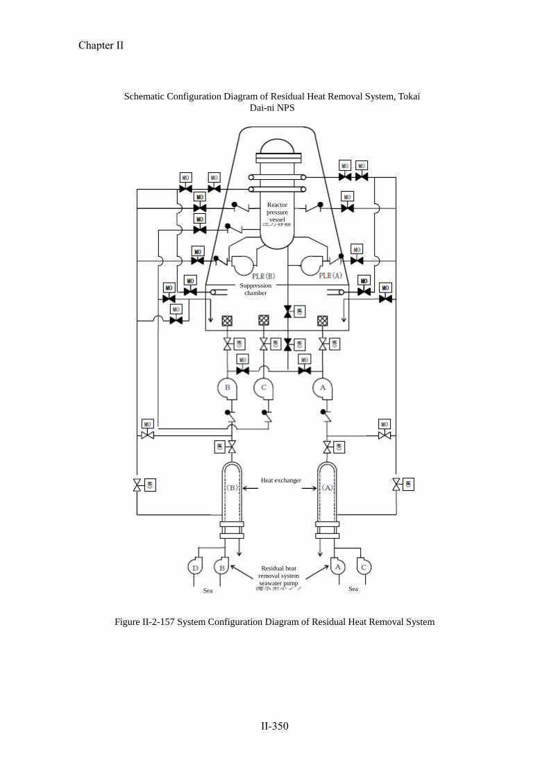
Figure II-2-157 System Configuration Diagram of Residual Heat Removal System
Schematic Configuration Diagram of Residual Heat Removal System, Tokai
Dai-ni NPS
Reactor
pressure
vessel
Suppression
chamber
Heat exchanger
Residual heat
removal system
seawater pump
Sea Sea
Chapter II
II-350

c. Status from the earthquake occurrence to cold shutdown
The major chronology is shown in Table II-2-60.
○ Situation immediately after the earthquake occurred (Figure II-2-158)
Under constant rated thermal power operation, along with the earthquake, the
Tokai Dai-ni NPS was scrammed due to a signal of major steam stop valve closed in
conjunction with turbine trip caused by turbine shaft bearing vibration large signal at
14:48 on March 11, 2011.
In the reactor scram, all control rods were normally inserted, after that, sub–critical
was confirmed (at 15:10 on the same day).
In this regards, reactor scram signal due to seismic acceleration high was sent one
second after scram signal caused by turbine trip.
Immediately after the earthquake occurred, although off-site power supply (275kV
and 154kV) had shut down due to the effects of the earthquake, three of the
emergency DGs (DG (2C), DG (2D), and DG (H)) were automatically started, and the
power supply for emergency equipments was secured by applying load to each. As for
supplying power source for 125V stored battery 2A, which is a DC-driven power
source for RCIC, it was supplied from the same generators (Figure II-2-159).
Due to changes in water level immediately after the reactor scram, HPCS, one of
the ECCSs, and RCIC were automatically started and a water injection function to the
reactor in a high pressure status of reactor was secured, with the water level of the
reactor thereby being maintained at the normal water level. The following
stabilization of the reactor water level was carried out by RCIC (the water source was
that of the CST at first, and then of S/P), and reactor pressure control was carried out
via the SRV.
Also, RHR was manually started (A system from 15:01 on the same day, and B
system from 16:40 on the same day) for decay heat removal, and cooling the S/P was
started.
Moreover, regarding the coffining function, due to change (decrease) in the water
level immediately after reactor scram, PCIS was normally operated (at 14:48 on the
same day) so that the PCV was isolated.
Similarly, due to change (decrease) in the water level immediately after reactor
scram, the reactor building ventilation system was automatically isolated, and the
usual ventilation system was shifted normally to the Filtration Recirculation and
Ventilation System (FRVS) and SGTS.
Chapter II
II-351

○ Effects of the tsunami (Figure II-2-160)
Regarding the scale of tsunami at the Tokai Dai-ni NPS, the initial tsunami arrived
at around 15:32, about 40 minutes after the mainshock, and the maximum tsunami
height after that was about 5.3 m.
At 19:01, about 4 and a half hours after the mainshock, since seawater flooded
seawater pump tanks of the north side (hereinafter referred to as ―north-side pump
tank‖) among those located the north and south parts of water intake, and seawater
pump for emergency DG (2C) (DGSW2C) used for cooling emergency DG (2C)
motor was submerged and automatically stopped, the shift supervisor determined that
operation of emergency DG is impossible and stopped emergency DG (2C). Along
with this, RHR (A) and RHRS (A and C) whose electricity were supplied from
emergency DG (2C) became disable to function, and also became impossible to
supply power to 125 V storage battery 2A which is direct-current power for RCIC.
However, since emergency DG (2D) including seawater pump for emergency DG
(2D) (DGSW2D) had no effects of the tsunami, the final heat sink by RHRS (B and
D) was secured.
○ Operation until cold shutdown
As a method of water injection into the reactor, reactor water level was secured by
using two systems (RCIC and HPCS).
Also, steam generated from reactor core was discharged to S/P, and was cooled at
RHR (B).
Regarding RCIC, 125V storage battery (2A) supplied it with power, but it was
required to take actions to extend the life of 125V storage battery (2A) in order to
keep the operation. Therefore, by utilizing power supply of emergency DG (2D)
which was operating robustly and operating spare charger*, power was fed to 125V
stored battery2A (Figure II-2-161).
* At inspection of 125V storage battery charger A or B, it is a spare charger for
feeding power to stored battery of each system, and it is a facility which can
supply electricity from one of the three systems of emergency bus as power supply
of charger.
Two systems of RHR were secured towards reactor cold shutdown, and, in order to
achieve more definite cooling, alternative power supply from DG (H) to secure power
supply that RHR (A) is operable, restoration of emergency DG (2C), or restoration of
off-site power supply, were considered.
Chapter II
II-352

At this time, it was determined best to secure HPCS, as well as RCIC, as one of
multiple methods to keep reactor water level until reactor cold shutdown is achieved.
Regarding RHR (B), it was decided to continue S/P cooling in order to keep the stable
status of PCV pressure, and, S/P cooling was to be continued immediately, with
reduction in pressure by SRV and reactor water level control by RCIC (by HPCS
when RCIC becomes impossible to continue its operation due to reduction in reactor
pressure).
After that, it was informed from load dispatching office that restoration of off-site
power supply (154kV) became possible (at 10:40 on March 13), and it was decided
that RHR (A) was used in SHC mode, and was started preparing for receiving
electricity from 154kV system of on-site power supply, and after the preparation was
completed through charging lines (at 12:32 on March 13), operation of receiving
electricity was carried out (at 19:37 on March 13).
After restoration of off-site power supply (154kV), it was confirmed that RHRS (A
and C) pump whose bottom part of motor was nearly submerged was robust, and
operation of RHR (A) was started in SHC mode through warming operation of SHC
piping, etc. (at 23:43 on March 14), and it achieved reactor cold shutdown (at 0:40 on
March 15).
○ Spent fuel pool
With the SFP water level alert being activated, since overflow was occurred around
the SFP due to sloshing caused by the earthquake, the SFP level was decreased about
20 cm from the normal water level.
Therefore, following the ―alarm procedure document‖, water injection into SFP by
using the water in CST was carried out (from 18:51 to 22:13 on March 11).
In this respect, although the water level of the pool was decreased, the condition
that spent fuels storage in the SFP was fully submerged (the top of fuel + about 7 m)
was continued.
Although FPC had been stopped due to loss of off-site power supply, after
confirmation of the stopped state and start-up preparation were carried out, the FPC
restored to the operating condition (demineralizer bypass operation) by means of
feeding power from the emergency DG(2D) (at 18:14 on March 12).
Chapter II
II-353

Table II-2-60 Main Chronology of Tokai Dai-ni NPS
Events, operation and others
March
11
14:46 Tohoku-District – Off the Pacific Ocean Earthquake occurred.
14:48 Automatic shutdown of turbine generator
Automatic shutdown of reactor
Insertion of all control rods
Loss of off-site power
Automatic startup and paralleling of emergency DG (3 sets: 2C, 2D, HPCS)
MSIV: closed
Automatic startup of high-pressure core spray system
Automatic shutdown of FPC
14:49 Automatic startup of RCIC
15:01 Start of cooling operation of RHR (A) S/P
16:40 Start of cooling operation of RHR (B) S/P
19:01 Automatic shutdown of sea water pump for emergency diesel generator 2C
(submersion under water due to tsunami)
19:21 Manual shutdown of RHR (A) pump, sea water pumps (A) and (C) for residual heat
removal system
19:25 Manual shutdown of emergency DG 2C
20:19 Start of charging for storage battery 2A via an reserve charger from emergency power
supply system 2D
21:52 Start of reactor pressure reduction operation (SRV)
March
12
13:11 Manual shutdown of RCIC (transition to water level control by high-pressure core
spray system)
18:14 Restart of FPC
March
13
19:37 Receipt of off-site power supply (nuclear line 1 of 154 kV system)
March
14
23:43 Start of SHC operation of RHR (A)
March
15
00:40 Cold Shutdown
02:46 Stop of S/P cooling operation of RHR (B)
Chapter II
II-354

02:49 Manual shutdown of emergency DG 2D
04:09 Manual shutdown of high-pressure core spray system pump
04:19 Manual shutdown of DG (H)
March
17
15:47 Receipt of off-site power supply (Tokai nuclear line 1 of 275 kV system)
March
22
22:10 Return to standby condition of emergency DG 2C
April 27 16:29 Receipt of off-site power supply (Tokai nuclear line 2 of 275 kV system)
Chapter II
II-355

Figure II-2-158 System Configuration Diagram of Tokai Dai-ni NPS (After Earthquake: Before Tsunami)
Substation
154 kV
Electrical system
Primary containment vessel
Reactor building
Stack for emergency gas treatment system
275 kV
Electrical system
Emergency gas treatment system
Filter
Substation
To turbine generator
From feed water pump
Startup
transformer
Standby
transforme
r
125 V Storage battery
(2A)
125 V Storage battery
(2B)
125V Storage battery
(HPCS)
Emergency diesel
power generator 2D
Emergency diesel
power generator 2C
DG 2D
Seawater
pump
HPCS DG
Seawater
pump
Diesel power generator for
high-pressure core spray
system
Residual heat
removal system
seawater pump
(A)
Residual heat
removal system
seawater pump
(C)
Main steam safety relief valve
Main steam isolation
valve
To
water-discharg
e (sea) To
water-discharge
(sea)
Low-pressure core
spray system
Residual heat removal
system seawater pump
(D) Condensate
storage tank
Residual heat
removal system
seawater pump
(B)
Reactor core isolation
cooling system
High-pressure core
spray system
Residual heat
removal system
(A)
Residual heat
removal system
(B)
Suppression pool
Rea
cto
r p
ress
ure
ves
sel
Loss
Loss
Legend red equipment: in operation, blue equipment: shutdown, mark: not
available
Chapter II
II-356

Figure II-2-159 Station Power Supply Sysytem Diagram of Tokai Dai-ni NPS (Power Supply Status before DG 2C Shutdown)
Tokai nuclear power
supply line Nuclear power
supply line Tokai nuclear power
supply line
Standby transformer Startup transformer 2B Power supply bus Startup transformer 2A
6900V System
480V System
Storage
battery Storage
battery
Reserve
charger
Storage
battery
Loss of Power supply Loss of Power supply Loss of Power supply
Chapter II
II-357

Figure II-2-160 Ssytem Configuration Diagram of Tokai Dai-ni NPS (After Earthquake: After Tsunami)
Transforming
station Reactor building
Primary containment vessel
Emergency gas treatment system
Filter
To turbiner generator
From feed water pump
Startup
transformer
Standby
transforme
r
Main steam safety relief valve
Main steam isolation valve
To
water-discharge
(sea)
Suppression pool
125 V Storage battery
(2A)
125 V Storage battery
(2B)
125V Storage battery
(HPCS)
Residual heat
removal system
seawater pump (D)
Residual heat
removal system
seawater pump (B) Condensate storage
tank
Residual heat
removal system
seawater pump
(A)
Diesel power generator
for high-pressure core
spray system
Emergency diesel
power generator 2D
Emergency diesel
power generator 2C
Residual heat
removal system
seawater pump
(C)
HPCS DG
Seawater
pump
DG 2D
Seawater
pump
Rea
cto
r p
ress
ure
ves
sel
Low-pressure core
spray system Reactor core isolation
cooling system
High-pressure core
spray system
Residual heat
removal system
(A)
Residual
heat removal
system (B)
To
water-discharg
e (sea)
Stack for emergency gas treatment system
275 kV
Electrical system Loss
Transforming station
154 kV
Electrical system
Loss
Loss
Legend red equipment: in operation, blue equipment: shutdown, mark: not
available
Chapter II
II-358

Figure II-2-161 Station Power Supply System Diagram of Tokai Dai-ni NPS (Power Supply Status after DG 2C Shutdown)
Tokai nuclear power
supply line Nuclear power
supply line
Tokai nuclear power
supply line
Power supply bus Startup transformer 2B Standby
transformer Startup transformer 2A
6900V System
480V System
Storage
battery Storage
battery
Reserve
charger
Storage
battery
shutdown
Loss of ower supply Loss of ower supply Loss of ower supply
Chapter II
II-359

d. Changes in main parameters
Changes in main parameters, such as the water level of the reactor and reactor pressure,
etc. until cold shutdown after the mainshock are shown from Figure II-2—162 to Figure
II-2-164. Also, records of highest (lowest) value of parameters and limits value of
designed value, etc. are shown in Table II-2-61. It was found that, regarding the water
level of the reactor, TAF + 4 m or more was secured, and, as for reactor pressure, changes
remained within the range of the maximum design pressure. It was then confirmed that
changes in all parameters remained within the range of designed value and limit values.
Table II-2-61 Main Plant Parameter Result of Tokai Dai-ni NPS
Limitation values Maximum (minimum) results
Reactor water level -4248 mm or more
(TAF: top of active fuel)
About -910 mm
(TAF: about +3,338 mm)
Reactor pressure 8.62 MPa or less
(maximum operating pressure) About 7.43 MPa
D/W pressure 279.5 kPa or less
(design pressure) About 12.5 kPa
S/P water temperature 104°C or less
(design pressure) About 54°C
S/P water level 8.427 m or less
(S/P vent line height)
About 7.403 m
(normal water level: +37.3 cm)
SFP water temperature 65°C or less
(technical specification) About 29°C
Chapter II
II-360

-2
-1
0
1
2
3
4
5
6
7
8
-5000
-4000
-3000
-2000
-1000
0
1000
2000
3/11 1
2:0
0
3/12 0
:00
3/12 1
2:0
0
3/13 0
:00
3/13 1
2:0
0
3/14 0
:00
3/14 1
2:0
0
3/15 0
:00
3/15 1
2:0
0
【原
子炉
圧力
(MPa)
】
【原
子炉
水位
(mm
)/発
電機
出力
(MW
)】
原子炉水位(mm)左軸
発電機出力(MW)左軸
原子炉圧力(MPa)右軸
有効燃料頂部
1500mm以上
(広帯域水位計指示値)
3/15 0:40
原子炉冷温停止
3/11 14:48
原子炉自動停止プロセスコンピュータ電源切替に伴う欠測
Figure II-2-162 Variation of Main Parameters (from March 11 till March 15) (No. 1)
14:48, March 11, 2011
Automatic shutdown of
reactor
Missing associated with switching of process computer power
supply
0:40, March 15, 2011
Cold shutdown of reactor
Top of active fuel
[Rea
cto
r w
ater
lev
el (
mm
)/g
ener
ato
r o
utp
ut
(MW
)]
[Rea
cto
r p
ress
ure
(M
pa)
]
1500 mm or more (wide band water
gage indicating value)
Reactor water level (mm) Left
axis Generator output (MW) Left axis
Reactor pressure (MPa) Right
axis
Chapter II
II-361

-2
0
2
4
6
8
10
12
14
-60
-30
0
30
60
3/11 1
2:0
0
3/12 0
:00
3/12 1
2:0
0
3/13 0
:00
3/13 1
2:0
0
3/14 0
:00
3/14 1
2:0
0
3/15 0
:00
3/15 1
2:0
0
【原
子炉
圧力
(MPa)
/ドラ
イウ
ェル
圧力
(kPa)
】
【S/P水
温(℃
)/S/P
水位
(cm
)】
S/P水温(℃)
S/P水位(cm)
ドライウェル圧力(kPa)
原子炉圧力(MPa)
3/15 0:40
原子炉冷温停止
3/11 14:48
原子炉自動停止
プロセスコンピュータ電源切替に伴う欠測
Figure II-2-163 Variation of Main Parameters (from March 11 till March 15) (No. 2)
Missing associated with switching of process computer power
supply
S/P water temperature ( C)
14:48, March 11, 2011
Automatic shutdown of reactor
0:40, March 15, 2011
Cold shutdown of reactor
[S/P
wat
er t
emp
erat
ure
(C
)/S
/P w
ater
lev
el <
cm>
]
[Rea
cto
r p
ress
ure
(M
pa)
/Dry
wel
l p
ress
ure
(kP
a)]
S/P water level <cm>
Dry well pressure (kPa)
Reactor pressure (Mpa)
Chapter II
II-362

0
5
10
15
20
25
30
35
40
3/11 1
2:0
0
3/12 0
:00
3/12 1
2:0
0
3/13 0
:00
3/13 1
2:0
0
3/14 0
:00
3/14 1
2:0
0
3/15 0
:00
3/15 1
2:0
0
【燃
料プ
ール
水温
度(℃
)】
燃料プール水温度(℃)
3/15 0:40
3/11 14:48プロセスコンピュータ電源切替に伴う欠測
Figure II-2-164 Variation of Main Parameters (from March 11 till March 15) (No. 3)
14:48, March 11, 2011
[Fu
el p
oo
l w
ater
tem
per
atu
re (C
)]
Missing associated with switching of process computer power
supply
0:40, March 15, 2011
Fuel pool water temperature (C)
Chapter II
II-363

e. Impact of radioactive materials upon the outside
○ Condition of the fuel in the reactors and spent fuel
From the time of the earthquake to cold shutdown, water level inside the reactor
has been maintained higher than the top of active fuel, TAF and the spent fuel pool
also has secured sufficient water level. Also, measurement results of the reactor
water and the water of the spent fuel pool are shown in Table II-2-62 and Table
II-2-63. The measurements have showed no change from the time before the
earthquake, and there were no measurement data which suggest the probability of
damage to fuel. Consequently, fuel damage is judged not to have occurred.
○ Measurement value of monitoring posts, etc.
Measurements of the monitoring post (MP) from the time of the earthquake to cold
shutdown are shown in Figure II-2-165 and Figure II-2-166.
The Tokai Dai-ni NPS has reached cold shutdown status at 0:40 on March 15, but,
just after that, from around 0:50, rise of measurement value of monitoring post (MP)
measurement was observed. The reason for rise of measurement value of MP is
estimated to be due to the accident at the Fukushima Dai-ichi NPS, and release of
radioactive materials to the atmosphere from the Tokai Dai-ni NPS is judged not to
have occurred.
・From the time of the earthquake to cold shutdown, as cooling for the reactor has
been working and reading of the ventilation stack monitor has been also stable at
normal level, noble gases were not released from the Tokai Dai-ni NPS.
・The time when the MP measurement value started to rise was after the cold
shutdown, and the southwesterly wind until March 14 changed direction to the
northeast from around 0:00 on March 15. The result of this change in wind was that
the NPS came to be in the downwind direction of the Fukushima Dai-ichi NPS.
・About ten minutes before the MP reading of the Tokai Dai-ni NPS rose, the reading
of the MP on the windward side (set up by Ibaraki Prefecture at Onuma, Hitachi
City) rose.
○ Release of a slight amount of radioactive materials
Around 21:50 on March 11, maintenance staff, who has been checking conditions of
equipments in the site affected by this earthquake, found overflowing water from the
drain funnel in the 2B battery charger room installed in the ground floor (uncontrolled
area) of the electric room of the combination structure.
As storage batteries in the battery charger room were used also for control power
Chapter II
II-364

supply of emergency DG (2D) necessary for operation of cool shutdown at the loss
of external power supply and the overflowing water was estimated to have a
possibility to affect the safety, the overflowing water was discharged to the
uncontrolled area near the top of the emergency diesel generator system room after
checking by a survey meter that the water was not contaminated.
In the subsequent investigation, as a result of measurement of tritium for samples
taken before the discharge, tritium was detected, and, by nuclide analysis using
germanium semiconductor detector, cobalt (Co-58 and Co-60) were detected.
Also, as the funnel was confirmed in the construction planning map to be
connected to the laboratory sump in control area on the ground floor of the service
building next to the combination structure, it was judged that liquid waste in the sump
had flowed back to the uncontrolled area and overflowed. As the released radioactive
materials were tritium (1.4×10⁻³
Bq/cm3), Co-58 and Co-60 (both were
4.6×10⁻⁵
Bq/cm3), and the water concentration outside the supervised area near the
NPS, which was a sum of the percentages to the limits of these nuclides (tritium
6×101Bq/cm
3, Co-58 1×10
0Bq/cm
3, Co-60 2×10
-1Bq/cm
3), was approximately one
three-thousand of the concentration limit, it was judged that there was no impact on
the environment.
Chapter II
II-365

Table II-2-62 Iodine Measurement Result of 131 Concentration in Reactor Water
Table II-2-63 Radioactivity Measurement Result of SFP water
Sampling date and time Reactor status Detected nuclides and
concentration
(Bq/g)
Notes
10:00, March 8, 2011 In operation Co-60: 2.64E-1
10:20, March 18, 2011 Cold shutdown Co-60: 7.66E+0
Mn-54: 2.08E-1
Zn-65: 1.71E-2
[Fuel soundness evaluation]
Radioactive material concentration of SFP water after shutdown of reactor due to the earthquake
disaster is higher than the value before the earthquake disaster due to effect such as shutdown of
cleaning system, but fuel is kept in sound state because no FP nuclides are detected.
Sampling date and time Reactor status Iodine 131 concentration
(Bq/g)
Notes
10:00, March 8, 2011 In operation 2.35E-2
10:30, March 18, 2011 Cold shutdown 4.34E-2
[Fuel soundness evaluation]
Iodine 131 concentration in reactor water after shutdown of reactor due to the earthquake disaster is
sufficiently low relative to 3.7E+1Bq/cm3
that is the fuel assembly sipping requirement, and fuel is
kept in the sound state.
Chapter II
II-366

1
10
100
1000
10000
3/11 0:00 3/11 12:00 3/12 0:00 3/12 12:00 3/13 0:00 3/13 12:00 3/14 0:00 3/14 12:00 3/15 0:00 3/15 12:00 3/16 0:00
モニ
タリ
ング
ポス
ト指
示値
(nG
y/h)
主排
気筒
モニ
タ指
示値
(cps
)
モニタリングポスト推移(2011年3月11日~3月15日)
モニタリングポスト (A)
モニタリングポスト (B)
モニタリングポスト (C)
モニタリングポスト (D)
主排気筒モニタ (A)
3/11 14:46
地震発生
3/15 0:40
冷温停止
3/11 22:00~3/12 12:15
計算機停電のため欠測
(中央制御室チャート指示は変動なし)
3/15 1:20頃
200nGy/hに指示上昇
3/15 7:50
最大4732nGy/hまで指示上昇
3/15 4:20頃~9:00頃
8cpsから最大10cpsまで上昇
3/14 15:00~15:26
計算機停電のため欠測
(中央制御室チャート指示は変動なし)
Figure II-2-165 Transition of Indicated Value of Monitoring Posts (from March 11 till March 15) (No. 1)
Monitoring post (A)
07:50, March 15, 2011:
Indicated value increased up to 4732 nGy/h.
Around 01:20, March 15, 2011:
Indicated value increased to 200
nGy/h.
14:46, March 11, 2011: Occurrence of earthquake
Mo
nit
ori
ng
po
st i
nd
icat
ed v
alu
e (n
Gy
/h)
Sta
ck m
on
ito
r in
dic
ated
val
ue
(cp
s)
22:00, March 11, 2011 12:15, March 12, 2011
Missing due to computer power failure
(no variation in main control room chart indicated
values)
15:00 15:26, March 14, 2011
Missing due to computer power failure
(no variation in main control room chart indicated values) 0:40, March 15,
2011
Cold shutdown
From around 04:20 till around 09:00, March
15: Indicated value increased from 8 cps up to
10 cps.
Monitoring post (B)
Monitoring post (C)
Monitoring post (D)
Stack (A)
Chapter II
II-367

1
10
100
1000
10000
2011/3/11 2011/3/11 2011/3/12 2011/3/12 2011/3/13 2011/3/13 2011/3/14 2011/3/14 2011/3/15 2011/3/15 2011/3/16
モニタリングポスト (A)
モニタリングポスト (B)
モニタリングポスト (C)
モニタリングポスト (D)
茨城県モニタリングポスト(大沼)
Figure II-2-166 Transition of Indicated Value of Monitoring Posts (from March 11 till March 15) (No. 2)
Monitoring post (A)
Monitoring post (B)
Monitoring post (C)
Monitoring post (D)
Ibaraki monitoring post (Ohnuma)
Chapter II
II-368

Ⅱ.
2.
(4
)②
(保安
院)
f. Stoppage of emergency DG seawater pump 2C due to tsunami
The stoppage of DGSW2C by this earthquake cut off the supply of power to one
of the systems of the reactor coolant system equipment. The details are described
below.
○ Description of the tsunami
Figures II-2-167 and II-2-168 show the extent and height to which the tsunami
reached. As a result of investigation of inundation damage at the water intake area
based on the video recorded by the security camera installed in the power station,
it was found that at around 15:35, the water intake area (height above sea-level
(―TP‖) of approx. +3.31m) was inundated up to a depth of approx. 1m (the depth
of inundation estimated based on the security camera video).
Further, an inundation of the water intake area of approx. 2m was confirmed at
16:51, followed by a series of inundations (1m or less).
Based on the result of on-site investigation of traces, it is assumed that the
tsunami reached approx. TP+5.3m at the Tokai Daini Nuclear Power Station.
The height of the traces and the reaching point of the tsunami in the power
station premises and surrounding areas will be clarified through upcoming
leveling (measurement of altitude difference from reference point).
○ Innundation of north pump tank where DGSW2C is installed
Structure of pump tank
The layout of the water intake pump area is shown on Figure II-2-169
Pump Area. Located at the center of the pump area is the circulation water
pump tank, with pump areas for safety-significant equipment, namely the
north-side and south-side seawater pump tanks, located on either side of it.
In the north seawater pump tank, DGSW2C pump, Auxiliary Sea Water
(ASW) system (A, C) pump and RHRS (A, C) pumps are located. In the
south seawater pump tank, DGSW2D, ASW (B), RHRS (B, D) and
HPCSDGSW are located.
Inundation of pump tank and damage on equipment (Figures II-2-169
and II-2-170)
Check of the north and south pump tanks showed inundation in the north
pump tank, but not in the south tank. As a result of inundation of the north
pump tank, DGSW2C was submerged completely under water and stopped
automatically. The top of the electric motor of DGSW2C is located about
Chapter II
II-369
Ⅱ.
2.
(4
)②
(保安
院)
1.8m from the bottom of the pump tank. On the other hand, ASW (A,C) and
RHRS (A, C) pumps sunk only up to around the bottom bearing of the
motor, and subsequent inspection and test-run showed no problems in the
function of the each pump.
Tsunami countermeasures of pump tanks
Figures II-2-171 and II-2-172 show the history of tsunami countermeasures
taken for pump tanks since the construction of Tokai Daini Nuclear Power
Station to present.
・1971: At the time of reactor establishment permit application, the north
pump tank did not have any bulkheading because the equipment
installation level at the water inlet (TP+3.31m) is higher than the tide level
observed at Hitachi Harbor (TP+1.46m).
・1997: As an early adoption of the ―Tsunami Assessment Method for Nuclear
Power Plants in JAPAN‖ issued by the Japan Society of Civil Engineers, a
bulkheading (TP+4.91m) was built for the north pump tank as a measure
against tsunamis.
・December 2008: Taking into account the highest tide level (TP+5.72m)
postulated in the ―Expected Scope of Tsunami Inundation on the Coast of
Ibaraki Prefecture‖ published by Ibaraki Prefecture, which is more stricter
than the tsunami postulated in the new seismic guidelines, decision was
made to install a new bulkheading of TP+6.11m.
・September 2010: The installation of bulkheading was completed.
・At the time of the earthquake (March, 2011), watertight sealing of the north
pump tank was ongoing as an activity following bulkheading installation.
Specifically, the plan for the north tank consisted of shutting off the drain
to the ASW strainer area, and improving the water-tightness of the cable
pit located in between the new and existing bulkheadings to prevent any
water coming in from there. The plan was due to be completed by end of
May 2011, and the activities were not started and ongoing, respectively.
For the south pump tank, all activities including water-tighting of the
pipe penetration had completed by March 9.
Cause of inundation of north pump tank (Figure II-2-169)
The new bulkheading (TP+6.1m), which was installed to improve the
Chapter II
II-370

Ⅱ.
2.
(4
)②
(保安
院)
safety margin against earthquakes and is higher than the tsunami (about
TP+5.3m), is assumed to have prevented the tsunami from flowing directly
into the pump tank.
However, due to the construction work which was going on around the
north pump tank, although the tsunami was lower than the bulkheading, sea
water could flow into the tank at the following places:
・ Drain opening between the pump tank and the ASW strainer area
・Cable pit which was not water-tight design
The inflow of water from these places submerged DGSW2C, and the rise
in shaft power of the motor-cooling fan due to water resistance raised current
value, activating the thermal relay that protects the motor from overload,
causing DGSW2C to stop automatically.
Temporary measures
・DGSW2C was restored through regular maintenance procedure after washing
and drying the stator. The pump was subsequently restored to standby
condition at 22:10 on March 22, 2011 following the integrity check operation
of the emergency DG (2C).
・For the north pump tank, the drain to the ASW strainer areas and the cable pit
was closed by concrete placement (Figure II-2-173).
・The power company has implemented emergency safety measures as further
measures against tsunami, and plans to incorporate the knowledge that will
be obtained through the overall investigation of the Great East Japan
Earthquake.
Chapter II
II-371

東海第二発電所 津波遡上高及び遡上が確認された範囲
原子炉建屋
海水ポンプエリア
+5.4m
+5.0m
+5.3m
+5.1m
+5.2m
+5.2m
+5.4m
+5.1m
+5.1m+5.2m+5.2m
+5.4m
+5.1m
※数値は全て標高表示(地殻変動による地盤の沈降は考慮していない)
東海港
タービン建屋
津波遡上高測定箇所
津波遡上範囲
敷地協会(東海発電所敷地を含む)
放水口
Fig. II-2-167 Tsunami Running-up Height and Area where Tsunami Running-up Have Been Observed
Reactor building Turbine building
Seawater pump area
Tokai port
Water discharge canal
Measuring point of tsunami running-up
height
Area where Tsunami Running-up Height and Tsunami Running-up
Have Been Observed at Tokai Dai-ni NPS
Area where tsunami running-up reached
Site boundary
(including the site of the Tokai NPS)
Chapter II
II-372

Fig. II-2-168 Crosssectional View of Buildings at Tokai Dai-ni NPS (Impacts of Tsunami)
Building construction level: TP +8.0 m
Condensate storage tank
Seawater pump
The tsunami running-up height is
presumed to have been approximately
+5.4 m with respect to the normal sea
level.
Part of the tsunami entered the area
where seawater pumps were installed.
Turbine building
Spent fuel pool
Reactor building
Reactor
pressure
vessel
Suppression pool
Main
generator
Main condenser
Chapter II
II-373

Fig. II-2-169 Photographs Showing Seawater Invading Routes in Northern Seawater Pump Area of Water Intake
Strainer chamber
Direction C (view of the northern seawater pump area seen from the
ocean)
Direction B (view of the entire seawater pump area seen from the
north)
Direction D (Photographs of ASW strainer seen from the mountain-facing side)
Tokai Dai-ni
NPS Portion A: Diagram of seawater pump area of water
intake
Revetment strengthening work
Portion A
Area at an elevation of
6.1 m or more Northern seawater
pump ASW strainer area
Cable pit Seawater invaded through the cable pit.
Valve room of circulation water pump
Circulating water pump vessel
*Height of the wall signified by red: TP +6.1 m or more
Direction D
Direction B
Direction C
ASW strainer area
Northern seawater pump vessel
Strainer
chamber
Strainer
chamber
Southern seawater pump vessel
Invasion route 2
Seawater pump for Emergency diesel generator
2C
Existing partition wall
Northern seawater
pump area
Cable pit
Seawater pumps A and C for residual heat removal
system
Seawater pump for emergency
diesel generator 2C
Invasion route 1
Opening of drainage side ditch
ASW strainer
ASW strainer area
About 2 m
Mountai
n-facing
side
Ocean-facing
side
Southern side wall
(newly constructed in
2010)
DGSW2C
(Tripped due to
submergence)
Ocean-facing side crane
rail
Existing partition
wall
Northern side wall
(newly constructed in
2010)
Direction C
Existing
partition
wall
Mountain-facing side
crane rail
Opening
To northern seawater pump area
Through portion to northern seawater
pump area (drainage side ditch) Mountain-facing side crane rail
Existing partition
wall Ocean-facing side crane rail
Seawater pump for emergency diesel
generator 2C Penetration to ASW strainer area
(drainage side ditch)
Northern side wall
Invasion of seawater
Opening
Cable pit
Direction D
Seawater pumps A and C for residual
heat removal system
Chapter II
II-374

Fig. II-2-170 Status of Seawater Invasion in Water Intake Pump Vessel on March 11
Top plate
Water
surface
DGSW-2C
Outside appearance of
electric motor (cross
section)
Seawater
Upper portion of electric motor for
DGSW-2C
The motor was submerge up to its top plate.
Chapter II
II-375

Fig. II-2-171 Details of Construction at Water Intakes for Anti-tsunami Measures (Construction of Partition Walls)
YYYY
YYYY
Ocean-facing side
Mountain-facing
side
Hand rail structure
Valve room of circulating water pump
Circulating water pump vessel
Valve room of circulating water pump
Circulating water pump vessel
Construction of partition wall (TP +4.91
m)
Opening
Cable pit
Opening
Cable pit
Strainer chamber
Strainer chamber
Southern seawater pump vessel
Strainer chamber
Circulating water pump vessel
Valve room of circulating water
pump
Location where the construction for
piping through portions was
completed
From MMYYYY to MMYYYY The height partition was raised when new
walls were constructed.
Opening
Cable pit
AWS strainer area
Northern seawater pump
vessel
Strainer
chamber
Strainer
chamber
Strainer
chamber
Str
aine
r ch
ambe
r S
trai
ner
cham
ber
S
trai
ner
cham
ber
New partition wall (TP +6.1 m) Outer partition walls were newly constructed for
supplementing strength poverty in order to raise the
height of existing partition walls.
AWS strainer area
Northern seawater pump vessel
Northern seawater pump
vessel
AWS strainer area
Details of construction etc. Notes
1971 Seawater pumps of emergency systems were installed in
both of the southern and northern pump vessels when
they were constructed. However, the northern pump
vessel, one of the two pump vessels, did not have
partition walls. This is because when the reactor
establishment license was applied for, it had been
concluded, from the recorded highest tidal level, TP
+1.46 m, observed at Hitachi port in Ibaraki prefecture
ever since July of 1956, that the tidal level would not
exceed TP +3.31 m, the elevation of the location of water
intake equipment.
The highest tidal
level was observed
in Kanogawa
Typhoon on
September 27,
1958.
July, 1993 Hokkaido-Nansei-Oki Earthquake occurred.
This event acted as impetus for creation of "Tsunami
Assesment Method for Nuclear Power Plants in Japan"
by Japan Society of Civil Engineers.
M 7.8 with the
highest tsunami
height 16.8 m
1994 Seismic BC conducted "Assessment of Historical
Tsunamis."
1997 The assessment result of "Tsunami Assesment Method
for Nuclear Power Plants in Japan" by Japan Society of
Civil Engineers was published in 2002. On the basis of
its information in advance, however, partition walls
(height: TP +4.91 m) were constructed at the northern
pump vessel as an anti-tsunami measure.
The anti-tsunami
measures was taken
from 1997 to 2001.
February, 2002 The highest tidal level was presumed to be TP +4.86m on
the basis of the assessment result of "Tsunami Assesment
Method for Nuclear Power Plants in Japan" by Japan
Society of Civil Engineers.
Southern seawater pump vessel
Southern seawater pump vessel
Southern seawater pump vessel
Chapter II
II-376

Fig. II-2-172 Status of Construction at Seawater Pump Area for Anti-tsunami Measures When Earthquake Occrred (March 11)
Diagram of seawater pump area of water
intake
Construction of new partition wall
Cable pit, filling construction for discharge
channels
Construction name etc. Notes 2010 2011
March 11
Earthquake occurred
June Sept.
Construction completed on Sept. 30
Nov. End of
March
Filling construction for piping penetration (11) portions completed on
March 9
End of
May Feb. 2
Filling construction for cable pits not completed
Filling construction for piping penetration
New partition wall
Circulating water pump valve chamber
Construction completed on March
9
Construction completed on Sept.
30
Circulating water pump vessel
AWS strainer area Opening
Cable pit
Strainer chamber
Southern seawater pump vessel
Strainer
chamber
Strainer
chamber
Filling of piping penetration
portions
Northern seawater pump
vessel
Chapter II
II-377
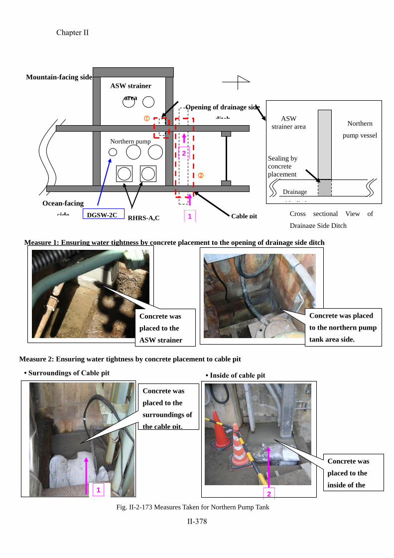
Measure 2: Ensuring water tightness by concrete placement to cable pit
• Surroundings of Cable pit • Inside of cable pit
Concrete was
placed to the
surroundings of
the cable pit.
Measure 1: Ensuring water tightness by concrete placement to the opening of drainage side ditch
ASW strainer
area
Ocean-facing
side
Mountain-facing side
Northern pump
vessel
RHRS-A,C
Cable pit
Opening of drainage side
ditch
DGSW-2C
2
ASW
strainer area Northern
pump vessel
Drainage
side ditch
Cross sectional View of
Drainage Side Ditch
Sealing by
concrete
placement
Concrete was
placed to the
inside of the
cable pit.
Concrete was placed
to the northern pump
tank area side.
Concrete was
placed to the
ASW strainer
area side.
Fig. II-2-173 Measures Taken for Northern Pump Tank
1
1
2
Chapter II
II-378

(5) An Outline of the Development of Events at Fukushima Dai-Ni NPS and Other
Power Stations
Fukushima Dai-ichi NPS, Units 1 through 3 suffered serious core damage, while
Fukushima Dai-ichi, Units 5 and 6 as well as Fukushima Dai-ni, Units 1 through 4
achieved cold shutdown without incurring core damage. The previous report laid out
these progressions in a function event tree, while also positing that the major
differentiating events were as below.
○ The failure to achieve early restoration of AC power due to the following reasons:
Electricity could not be provisionally procured from adjacent units due to
simultaneous loss of AC power.
Electrical switchboards and other peripheral systems were inundated by the
tsunamis.
External power supply and emergency DG could not be restored in the early
stages.
○ The inability to maintain core cooling until power was restored, even though
accident management following total loss of AC power enabled core cooling for a
period of time.
○ The tsunami-induced loss of function in the system for transferring heat to the sea,
the ultimate heat sink.
○ The inadequacy of the substitute method for removing decay heat from the PCV.
In this report, NISA created the sequence of events shown in Figs. II-2-174 to
II-2-176 with respect to the function event tree regarding the progression of events in
the Fukushima Dai-ni NPS and other NPSs and explained how cold shutdown was
achieved, seeing that there was no damage to the reactor cores.
1) Fukushima Dai-ni NPS (Figure II-2-174)
a. Securing of the AC power supplies
At the Fukushima Dai-ni NPS, AC power supplies were successfully secured as
a line of external power supplies was secured at the NPS as a whole.
Although no emergency DG for Unit 1 or Unit 2 was in a usable condition
because of the tsunamis, the loss of all AC power supplies was avoided because
external power supplies were secured. In Unit 3 and Unit 4, one or more
systems of emergency DGs were secured.
Chapter II
II-379

b. Core cooling
In Unit 1 and Unit 2, the cores were successfully cooled as the turbine-driven
water injection system was secured and an electrically-driven water injection
system other than all of the ECCS, which became unusable, was secured.
In Unit 3 and Unit 4, the cores were successfully cooled as the turbine-driven
water injection system was secured and the electrically-driven water injection
system. including a part of ECCS and others, was secured.
c. Removal of decay heat from containment vessels
In Unit 3, as a system of RHR had been secured, cooling continued to reach
the status of cold shutdown without incident.
On the other hand, as for Unit 1, Unit 2 and Unit 4, all of the heat removal
functions had been lost due to the tsunamis. Cooling was conducted after
temporarily restoring a system of RHR by replacing the motors of pumps for
emergency equipment cooling, receiving electricity from temporarily installed
cables and from high voltage power supply vehicles, and by suppressing the
pressure increase in the primary containment vessels using several kinds of
cooling functions. As a result, the status of cold shutdown could be realized
without reaching circumstances which would require PCV venting. The time
necessary for the temporary restoration of RHR as well as the start of cooling
since the influence of the tsunamis, such as the shutdown of the emergency DGs,
began to develop was around 58 hours at Unit 1, around 64 hours at Unit 2, and
around 72 hours at Unit 4.
2) Onagawa NPS (Figure II-2-175)
a. Securing of the AC power supplies
At the Onagawa NPS, a line of external power supplies was secured for the
NPS as a whole. At Unit 1, external power supplies became unusable as
power supplies could not be distributed to emergency distribution boards due to
a fire in the distribution boards for regular use; however, AC power supplies
were finally secured as all the emergency DGs started up normally.
At Unit 2 and Unit 3, AC power supplies were successfully secured with
external power supplies.
Chapter II
II-380

b. Core cooling
At Unit 1 and Unit 3, both the turbine-driven water injection system and the
electrically-driven water injection system were secured, enabling successful
cooling of the cores.
Regarding Unit 2, which was on the process of reactor start-up by pulling
control rods, the temperatures of the reactor water was below 100oC, and it
immediately shifted to a cold shutdown status because a scram was conducted
automatically.
c. Removal of decay heat from containment vessels
As for Unit 1 and Unit 3, all the RHR were secured and cooling conditions
were maintained, enabling a cold shutdown status to be reached.
Regarding Unit 2, the temperature of the core was below 100oC, and the status
shifted to cold shutdown. A system of RHR became unusable due to the
subsequent tsunamis but another system of RHR was usable; therefore, decay
heat removal was successfully secured.
3) Tokai Dai-ni NPS (Figure II-2-176)
a. Securing of AC power supplies
At the Tokai Dai-ni NPS, the distribution of three external power supply lines
was stopped, and as a result external power supplies were lost. All emergency
DGs started up normally. Although a system of emergency DG became unusable
due to the subsequent tsunamis afterwards, AC power supplies were secured by
another system of emergency DG and DG(H).
b. Core cooling
As only a single system of power supplies was secured by emergency DGs,
the number of electrically-driven water injection system secured was thus also
limited to one; however, it functioned without incident, resulting in the
successful implementation of core cooling.
c. Removal of decay heat from containment vessel
As only a single system of power supplies was secured by emergency DGs,
the number of RHR secured was also limited to one. For this reason, while it
took a longer time, continued cooling enabled it to reach the status of cold
shutdown.
Chapter II
II-381

Fig.II-2-174 Functional Event Tree for Fukushima Dai-ni NPS Units 1 to 4
Event that occurred
Reactor shutdown
AC power supply Core cooling Removal of decay heat from the PCV Core state
Earthquake and Tsunami
Reactor scram
Off-site power supply
Emergency DG
interchange of power supply
Main steam/ feedwater/ condensate systems
Turbine driven injection system (RCIC)
Motor driven injection system (ECCS) (HPCS, LPCS, LPCI)
Motor driven injection system (other than ECCS) (such as MUWC) and depressuriza-tion operation (SRV)
Heat removal with RHR
Recovery of RHR function (including functional recovery of alternative power supply and seawater pumps)
PCV vent (before core damage)
Cold shutdown, core damage, PCV damage, etc.
(Succeeded)
(Succeeded)
(Succeeded)
(Succeeded)
(Succeeded)
(Succeeded)
(Succeeded) (Succeeded)
(Succeeded)
(Succeeded)
(Succeeded)
(Succeeded)
(Failed)
(Failed)
(Failed)
(Failed)
(Failed)
(Failed)
(Failed)
(Failed)
(Failed)
(Failed)
(Succeeded*)
(Failed)
(Failed)
(Unit 3)
(Unit 4)
(Units 3 and 4)
(Units 1 and
2)
Cold shutdown
Cold shutdown
Unit 4: At 07:15, March 15
Long-term cooling required
Unit 1: At 17:00, March 14 Unit 2: At 18:00, March 14
Cold shutdown
PCV damage
Long-term cooling required
PCV damage * Actuation request was not issued for Unit 3.
Chapter II
II-382

Fig.II-2-175 Functional Event Tree for Onagawa NPS Units 1 to 3
Fig.II-2-176 Functional Event Tree for Tokai Dai-ni NPS
(Succeeded)
(Units 2 and 3)
(Succeeded) (Succeeded)
(Succeeded
)
(Succeeded*)
(Succeeded)
(Succeeded
) (Succeeded)
(Succeeded)
(Succeeded)
(Succeeded
)
(Failed)
(Failed*)
(Failed) (Failed)
(Failed)
(Failed) (Failed)
(Failed) (Failed)
(Failed)
(Failed)
(Failed)
(Failed)
(Failed)
(Lost)
(Unit 1) PCV damage
Long-term
cooling required
Cold shutdown
PCV damage
Cold shutdown
Long-term
cooling required
Cold shutdown
Cold shutdown
Unit 2 (at 14:49, March 11) Unit 3 (at 1:17, March 12)
Unit 1 (at 0:58, March 12)
While Units 1 and 3 were in power operation, Unit 2 was in start-up operation (where the reactor was not critical and the reactor water temperature was less than 100 degrees Celsius) right after the earthquake.
* Actuation request was not issued for Unit 2.
Event that occurred
Reactor shutdown
AC power supply
Core cooling
Removal of decay heat from the PCV
Core state
Earthquake and Tsunami
Reactor scram
Off-site power supply
Emergency DG
Interchange of power supply
Main steam/ feedwater/ and condensate systems
Turbine driven injection system (RCIC, HPCI (Unit 1 only))
Motor driven injection system (ECCS) (HPCS (Units 2 and 3 only), LPCI etc.)
Motor driven injection system (other than ECCS) (CRD, MUWC) and depressurization operation (SRV)
Heat removal with RHR
Recovery of RHR function (including functional recovery of alternative power supply and seawater pumps)
PCV vent (before core damage)
Cold shutdown, core damage, PCV damage, etc.
(Succeeded) (Succeeded)
(Succeeded)
(Succeeded)
(Succeeded)
(Failed)
(Failed)
(Failed)
(Failed)
(Failed) (Failed)
(Lost)
(Actuated)
Cold shutdown
Long-term cooling
required
Cold shutdown
PCV damage
Event that occurred
Reactor shutdown
AC power supply
Core cooling
Removal of decay heat from the PCV Core state
Earthquake and Tsunami
Reactor scram
off-site power supply
Emergency
DG
Interchange of power
supply
Main steam/ feedwater/ and condensate systems
Turbine driven injection system (RCIC)
Motor driven injection system (ECCS) (HPCS, LPCS, LPCI)
Motor driven injection system (other than ECCS) (MUWC etc.) and depressurization operation (SRV)
Heat removal with RHR
Recovery of RHR function (including functional recovery of alternative power supply and seawater pumps)
PCV vent (before core damage)
Cold shutdown, core damage, PCV damage, etc.
Chapter II
II-383

Fig.II-2-177 Functional Event Tree for Fukushima Dai-ichi NPS Units 1 to 3
(Extracted from the last report)
Event that occurred
Reactor shutdown
Core cooling
Core state
Reactor depressurization
Hydrogen control
Earthquake and Tsunami
Reactor scram
AC power supply
IC requiring no AC power supply, t urbine driven injection system (RCIC, HPCI)
Recovery of the power supply
Heat removal with RHR
Recovery of RHR function (including functional recovery of alternative power supply and seawater pumps)
Cold shutdown, core damage, PCV damage, etc.
PCV cooling system
Reactor depressurization using SR valves, etc.
Core injection
Fire extinguishing system diesel pumps or fire fighting pumps, etc.
PCV injection
Off-site power supply
Emergency DG
Recovery of the off-site power supply, recovery of emergency DG, or interchange of power supply
Removal of decay heat from the PCV
PCV vent (before core damage)
PCV spray (including fire extinguishing system sprays)
PCV vent (after core damage)
PCV injection (including fire extinguishing system injection into reactor, etc.)
FCS (including nitrogen purge)
Final state
Cold shutdown, core damage, PCV damage, etc.
(Succeeded)
(Actuated)
(Lost)
(Actuation failed)
(Not actuated)
(Failed to recover)
(Recovered)
Core damage
Core damage
Though PCV vent was attempted for 1F2, it is not sure whether the reactor was depressurized or not.
The underlined sequences indicate that they assumed major RPV damage.
Explosion occurred near the S/C. However, it was not confirmed if it had occurred within the PCV or not.
Core damaged in all the following situations.
PCV leak
(Deteriorated seals are presumed)
Estimated accident sequence for 1F3
PCV damage
(Hydrogen
explosion)
Estimated accident sequence for 1F2
PCV damage (MCCI)
PCV damage (MCCI)
PCV damage (MCCI)
PCV damage (MCCI)
PCV leak (Deteriorated seals are presumed)
Possibility of PCV damage (DCH)
PCV damage
(pressurization)
PCV leak
(Deteriorated seals are presumed)
Estimated accident sequence for 1F1
PCV leak (Deteriorated seals are presumed)
Possibility of PCV damage (DCH)
PCV damage (pressurization)
PCV damage (hydrogen explosion)
Cold shutdown
Cold shutdown
PCV damage
Long-term cooling required
(Actuated) (Actuated)
(Actuated)
(Actuated)
(Actuated)
(Actuated)
(Actuated)
(Succeeded)
(Succeeded)
(Succeeded)
(Succeeded)
(Succeeded)
(Succeeded)
(RPV damage)
(RPV damage)
Chapter II
II-384