1. nasa glenn research center battery activities … · density 460 wm 'ultra-hlgh" 530...
TRANSCRIPT
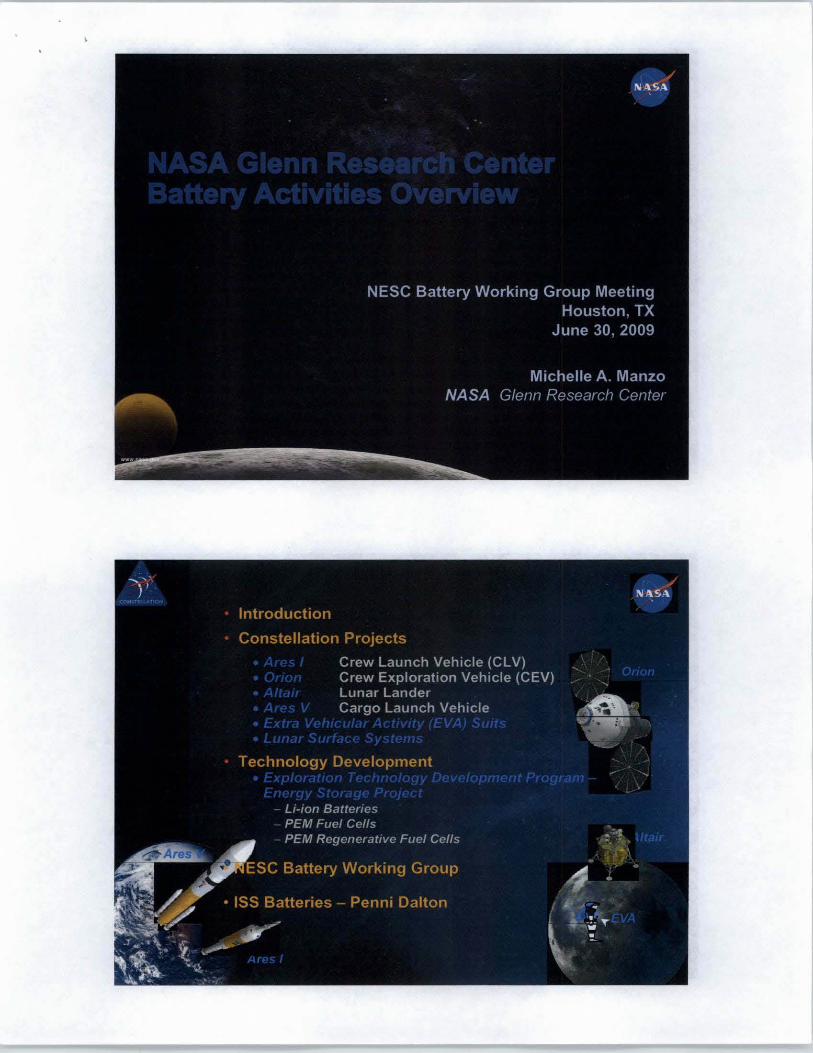
1. NASA Glenn Research Center Battery Activities Overview - for the NESC Battery Working Group Meeting in Houston, TX - June 20, 2009
NASA Glenn Research Center Battery Activities Overview
Michelle A. Manzo
NASA Glenn Research Center
This paper will provide an overview of the planned energy storage systems for the
Orion Spacecraft and the Aries rockets that will be used in the return journey to the
Moon and GRe's involvement in their development. Technology development goals
and approaches to provide batteries and fuel cells for the Altair Lunar Lander, the new
space suit under development for extravehicular activities (EVA) on the Lunar surface,
and the Lunar Surface Systems operations will also be discussed.
https://ntrs.nasa.gov/search.jsp?R=20120016631 2018-09-19T18:30:42+00:00Z


1.1 Project Management 1.2 Systems A ..... ments
7.0 Education and Public Outreach
2.0 lithium-Ion Batteries
2.1 Battery Task Management
2.2 High Energy Cell (for LSS) 2.2.1 HE-Unique Component Develop. 2.2.2 HE Cell Development 2.2.3 HE KPP A ..... m.nts
2.3 Ultra-High Energy Cell (for EVA & Altair)
2.3.1 UHE Component Development 2.3.2 UHE Cell Oevelopment 2.3.3 UHE KPP As .... ments
2.4 Safety, Packaging, and Control 2_4.1 II Conflguralion 2.4.2 External Safety Davie 2.4.3 Control Methodologies
3.0 Fuel Cen Systems
3.1 Fuel Cell Talk Management
3.2 Primary Fuel Cell Development 3.2.1 Stack.
3.2.1.1 B.aeUne Stacks 3.2,1.2 Alternative Stacks
3.2.2 BOP and System Tntlng
3.3 High-P Electrotysla Development
3.4 Regenerative Fuel Cell Technology
3.5 Crou-Cuttlng Tech Development 3.5.1 P. S Ive Therm. I Control 3.5.2 Advanced MEAt;
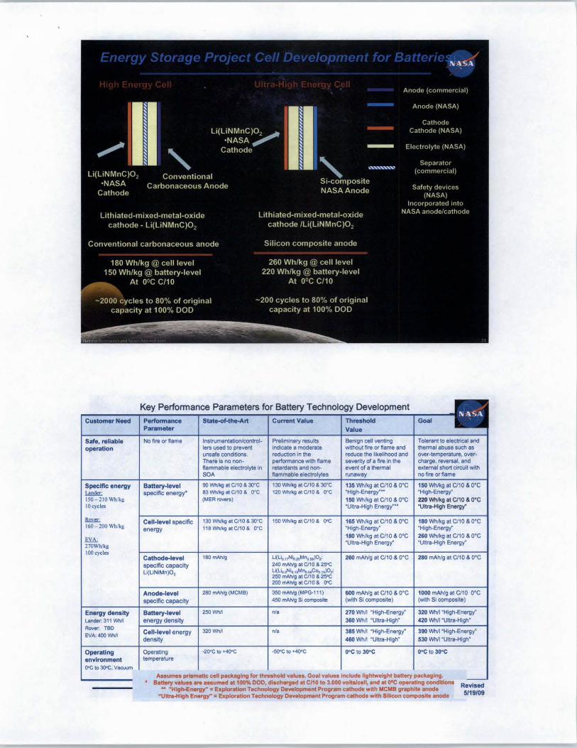
Key Performance Parameters for Battery Technology Development
Customer Need Perfonnance StatH)f-the-Art Cumtnt Value Threshold Goal Parameter Value
Safe, reliable No fire Of flame Instrumentation/control- Preliminary results Benign ceR venting Tolerant to electrical and operation lers used 10 prevent Indicate 8 moderate without fire or flame and thermal abuse sUCh as
unsafe conditions. reduction In the reduce the likelihood and OYef-\emperature.over-There Is no non- periormance with flame severity of a fire in the Charge, reversal, and flammable electrolyte in retardants and non- event of 8 thermal sKlemal short circuit with SOA , Amow", no fire Of flame
Specific energy Battery-level 90 'Mv'kg 8\ ClIO & 3Q-C 130 W'MIg IICltO & ~:~ 135 \'VhIkg at CltO & O"C 150 WhtKg al ClIO & O'C
"""'" specific energy' 83 Whikg lit ClIO & Q"C 120 'Nh/kg 8\ CIt 0 & O·C "High-Energy"-' "High-Energy"
ISO - 210Whlkg (MER 1'OYefS) 150 'vVh/kg a\ CIt 0 & O' C 220 Whtkg at ClIO & O·C LO cycles ·Ultra-High Energy'°' "Ultra-High Energy"
&l= Cell-level specific 130 WhIkg at Cfl 0 & 3I)'C 150 Whlkg ,tC/l0 & OOC 165 Vv'h/kg at ClIO & O' C 180 Whlkg at ClIO & O'C 160 - 200 WhIk,g energy 118WhlkgtltC/l0& O'C ·Hlgh·Energy" "High-Energy"
fYA; 180 IMI/kg at ClIO & O'C 260 Wh/kg a\ CltO & O' C
270Whlkg ·Ultra.High Energy' 'Ultra-High Energy'
IOOcydes Cathode-level ,eo"""" 260 mAhfg at CltO & O' C 280 mAh/g at Cit 0 & o-C
specific capacity 25'C
U(UNIMn)02 :';:; Anode-level 280 ITIAhfg (MCM8) 350 mAhfg (MPG-ll1) 600 mAhlg a\ CltO & O'C 1000 mAhlg at ClIO O'C
specific capacity 450 mAIVg SI composite (with SI composite) (with SI composlte)
Energy density Battery.level 250WM N' 270 WM I 320 _
Lander: 311 'MIll energy density 360 WM .",; .. _";",'- 420 Wh/l Rover; TBD
Ce ll· /evel energy 320WM N' 3851NM "High-Energy" 390 WM "High-Energy" EVA: 400 'MIll
density 460 WM 'Ultra-Hlgh" 530 WhIt 'Ultra-High'
Operating Operating -21)<Cto+~ -5O"C to +o4O"C OOC to 300c K to 300C environment temperature
OOC to JOOC. Vacuum
Assumes prismatic cell packaging for threshold values. Goal vatun include lightweight battery packaging. -. Sattety valu.s are a .. umed at 100% DOD, discharged at ClIO to 3.000 voltalcell, and at 01lC oporatfng condltkma Revised - "High-Energy": Exploration Technology Development Program cathode .,lth MCMB graphite anode
"Ultnl-High Energy" IE exploration TechncHogy Development Program cathode with Silicon composite anode 5119/09

Lith i um-Based
High Energy
Cell "A"
Ultra-High
Energy Cell "B"
Safety, Packaging
and Control
BASIC A
Rate Capability up to CIS
Storage and Calendar Ufe
Cost to TRL 6 6.S
Life
Rate Capability up to C/2 2.S
Master Schedule
OPTION Fligi,tw·'b" 1A
Rev
Cathode
U(UNMC)02 (ETDP)
U metal
Umetal

200 --- - -- ---- --- ---- ------- -------- --- ------
150 ....................................................................... _ ....................................................... .
100 ............. .
"--=_JII -IL------= .. :.:'=-Tpo= .. =-·-~I- - IL __ -----r _ __ -=""j .... :::·=--__ , __ ----'I -I
50 I u-s
° 2. ~ ~ 0= u~ _"u £" ~iQ
" :l :l •
~ ~ 6~_ ~~ ~" ::f:0;~ o. ~~~ N E iil E c ,,0 ~
~ ~ z e. :l
li(Nio_33MnO_33COo.33)02 Si-based Composrte
Sl-based Com~
Li metal
Limetal
li(LiNMC)02 (ETDP) Li metal 13.1
li metal


Minimize volume expansion during cycling
Minimize Irreversible capacity loss
250 cycles
High specific capacity at practical discharge rates
Low volume per unit mass
Minimize 1.t cycle irreversible capacity loss and
oPursuing various approad1es 10 optimize the anode structure to accommodate volume expansion of the silicoo
oNanostructured Si composlte absol'bs strain, resists active particle isolation on cycling olncorporatlon of elastic binders In $i -graphite and Si-C matrices -Improvement of mechanical Integrity by fabricating structure to allow for elastic defonnatlon
-Protection of active sites with functional binder additives oPre .. Uthlation approaches are possible 'Nanostruclured Si resists fracture and surface renewal
loss of contact with active partides reduces cycle life. Addressing volume changes and improvement of mechanical integrity will Improve cycte life
-Vary stoichiometry to detennine optimum chemical fonnulation -Reduce particle size -Experiment with different synthesis methods to produce materials with physical properties such that their specific capacity is retained on production scale
'Vary cathode synthesis method to optimize properties that can: -Improve energy density -Improve ability to cast cathode powders -Facilitate incorporation of oxide coatings, which have the potential to increase rate capability and reduce capacity fade to extend cycle life
-Surface modification via coatings to improve cathode-electrolyte interfacial properties ·Improves capacity retention

Electrolyte that is stable up to 5V
Non-flammable or flame retardant electrolyte
High voltage stable, non-flammable or flame retardant electrolyte (combination of both properties in one electrolyte system)
Electrolytes possessing the requisite physical properties to ensure good rate capacity (adequate conductivity) and compatibility (wettability).
Experiment with different electrolyte formulations and additives with potential to improve high voltage stability. Study interactions at both electrodes
Develop electrolytes containing additives with known flame retardant properties. Perform flame retardance assessments on developments that exhibit suitable electrochemical performance
Combine flame retardant additives with electrolyte formulations with high voltage stability. Operate systems to high voltages and investigate impacts on power capability and life.
Develop electrolytes that are not excessively viscous to ensure that the ionic conductivity is sufficiently high over the desired temperature range and the separator wettability is adequate.

Safe Electrodes
Safe electrolyte
r-Approach .. L - ~ - ~
•
- Appro -. - . • - - ,- - - -- -
· Develop materials to improve tolerance to an electrical abuse condition ·Approach 1: Develop a high-voltage stable (phosphate) coating on a cobaltate cathode particle to increase the safe operating voltage of the cell and reduce the thermal dissipation by the use of a high-voltage stable coating material (cobalt phosphate). ·Approach 2:Oevelop a composite thermal switch to shutdown cell reactions safely using coatings on the current collector substrates
·Development of advanced high voltage, non-flammable/flame-retardant electrolytes (via electrolyte task)

FlowThrough H, 0 ,
N.tloMI AMonautlc~t~'~i1I!!1'ItJi!''Parameters for Fuel Cell Technology Development
Customer Need Performance Parameter SOA Current Threshold (alkaline) Value· Value-
(PEM) (@3 kW)
System power density
Fuel Cell 49 Wfkg nia 88WIkg Altair: RFC (without tanks) nia nia 25 W/kg
3 kW for 220 hours Fuel Cell Stack power density continuous, 5 .5 kW peak.
nia nia 107 Wlkg
Fuel Cell Balance-of.plant mass nia nia 21 kg
Lunar Surface Systems: MEA efficiency @ 200 mAlcrnZ TBD kW for 15 days For Fuel Cell 73% 72% 73% continuous operation Individual cell voltage O.90V O.89V O.90V
Rover: TBD For Electrolysis nia 86% 84%
'Based on hrruted small-scale Individual cell voltage nia 1.48 1.46 testing
""'Threshold and Goal values For RFC (Round Trip) nia 62% 62% based on fuU·scele (3 kW) System efficiency@ 200 mAJcrnZ
fuel cell and RFC technology. fuel Cell 71% 65% ... • 71%
" 'r eledyne passive flow Parasitic penalty 2% 10% 2% through WIth latest MEA
···· Includes high preSSUl'e Regenerative Fuel Cell ..... nia nia 43%
penalty on electrolysis Parasitic penalty nia nia 10% efficiency 2000 psi High Pressure penalty nia nia 20%
Maintenance-free lifetime Maintenance-free operating life
Altair. 220 hours (primary) Fuel Cell MEA 2500 hrs 13,500 hrs 5,000 hrs
Surtace: 10,000 hours (RFC) Electrolysis MEA nia nia 5,000 hrs
Fuel Cell System (for Altair) 2500 hrs nia 220 hrs
Regenerative Fuel Cell System nia nia 5,000 hrs
Goal-
(@ 3 kW)
136 W/kg
36 W/kg
231 Wlkg
, k, 75% O.92V
85% 1.44
64%
74% 1%
54% 5% 10%
10,000 hrs
10,000 hrs
220 hrs
10,000 hrs
5122108

l .b 8t,,:k'" (50 cm2i4-C.tt )
l.b SlKk IJ (50 cm'l4-Cell )
Non Flow-Thru TKhnotogy
, .. jot MII .. to" ..
SItort Stack', (150
Short StKk 12 (150
Non Flow-ThnI TKhnology (EnglnHl'1ng Modtol)
Progression of Primary Fuel Cell Hardware from Small-Scale MEA Hardware Description Infuolo Primary Fuel Cell Hardware "
Laboratory Units Laboratory stack Is 50 em! Stainless Steel
lab stack #1 is graphite. Deliverable from SBIR contract. 4 cells. 40 - 80 W
111 Non-Flow-Through stack at NASA. 111 balance-of-plant {BOP #1}
lab stack #2 incorporates NASA flat plate heat pipes and MEAs. 4 cells. 40 - 80 W X Partially includes innovative assembly technology.
Stainless steel plate used to accommodate heat pipe.
Lab stack #3 ,u,ly , 1 4cells.4O-80W
Lab stack #4 fully integrates innovative assembly technology with 12cells.100-200W reactant pre-humidification and product-water dissolved gas removal 2nd balance-of-plant (BOP #2) with
autonomous
Large-Area Units large-area stack Is 150 cm! Stainless Steel
Large-area cell design based on lab stack test data.
X Short stack has 4-cells. 3rd balance-of-plant (BOP #3) Two units will be delivered. both of the same design.
Breadboard system is a quarter-scale (35-40 cells) stack. 35 - 40 cells. -1 kW
X 4th balance-of-plant (BOP #4). fully This unit will be used for TRl-5 testing.
autonomous
Engineering Model Based on Breadboard design Uses final materials (e.g . Niobium)
X I mod.1 to b. used for TRL-1\ t •• tlng 150 em'. - 140 cells. 2 - 3 kW
www.n .... gov


100.0
911.0 /II'
" ~ ~IEA
" ~ ............... I\JIIO -
110.0
70.0
FIIIc.l1EA -(IIS)(7a) -1Z'IIo
30.0 ~ - _IIIrIpRFC ..... --,
· ' iCJ 20.0 A_.
I ,. 0.'
1 .. 1------10.0
1 I-__________ -=~ ______ ~ .. ~'~ .. ~~~.~~ 0.'
0.0 0.00
l ~afoW
o .. 1000 1500
curNnt denoJty, mAlcm2
500.00 1I11III.00 1500.00 Current density. mAlcm2
(seal.: 0 - 2000 rnA/em')
1I11III.00
2001 COmparteon of JPL'. beet Irtdlum-cloped ruthenium with the 1'-': vendor MEA.hewn 30mV performance Improvement by the NASA mm.rt.I.

'SBIRs developing alternative non·flow-lhrough fuel cell technology, balanced high-pressure electrolysis technology,
improved MEAs, and advanced balance-ot·plant components for electrical and thermal management

•
Binding Procurements - guidelines related to requirements for the b<lttery system th.1t should be considered at the time of contract award
Wet Life of Ni-H; .. Batteries - issues/strategies for effective storage and impact of long-term storage on performance and life
Generic Guidelines for Lithium-ion S;]fety. Handling and Qualification - St;tndardized appro;lches developed and risk assessments
Lithium-ion Performance Assessment - survey of manufacturers and capabilities to meet mission needs. Guidelines document generated
Conditions Required for using POlich Cells in Aerospace Missions .- focus on corrosion, thermal excursions and long-term performance issues. Document defining
requirements to maintain performance and life
High Voltage Risk Assessment - focus on safety and abuse tolerance of battery module assemblies. Recommendations of features required for safe implementation
Procedure for Determination of Safe Charge Rates - evaluation of various cell chemistries and recommendation of safe operating regimes for specific cell designs
Lithium-ion Battery Source Material Availability - provide additional support for the governmental Title 3 effort aimed at ensuring a constant supply of source material
NASA A ernment-industry forum focused on b.Jttcry evelopments andissues (held an e Fall)