1 model 802 center mount adapter bi-directional … model 802 center mount adapter for new holland...
TRANSCRIPT

1 Model 802 Center Mount Adapter
For New Holland 9030 & TV140 Bi-Directional Tractors
PARTS CATALOG
TABLE OF CONTENTS
Frame & Tractor Linkage......................................................................................................................................2,3
Header Linkage & Float Group.............................................................................................................................4,5
Header Drive Hydraulics – with MacDon Pump.................................................................................................. 6-9
MacDon Pump/Gearbox Assembly ..................................................................................................................10,11
Header Drive Hydraulics – with New Holland Auxiliary Pump ........................................................................ 12-15
Header Driveline...............................................................................................................................................16,17
Header & Reel Lift Hydraulics – Serial No. 124499 and below........................................................................18,19
Header & Reel Lift Hydraulics – Serial No. 124500 and above .......................................................................20,21
Header Lift Cylinder – 2.5” Bore Seal Kit ..............................................................................................................22
Electrical ................................................................................................................................................................23
Hay Conditioner Forming Shields & Mounting Group ......................................................................................24,25
Decals...............................................................................................................................................................26,27
NUMERICAL LIST ..................................................................................................................28,29 ABBREVIATIONS
L/H - left hand (Determined from Operator's position, facing forward.) R/H - right hand I.D. - inside diameter O.D. - outside diameter A/R - as required (quantity varies) REF - reference, part number called up elsewhere in catalog SUB - Substitute (Revised design may be used to repair previous design when stock is depleted.) NC - national coarse thread NF - national fine thread NOTE: Common hardware is not illustrated. Alphabetic references are used to designate position and description of these items. When ordering, be sure the complete and proper serial number is given. SERIAL NUMBER BREAKS The side of the serial number on which the dash (-) appears determines whether the part is used "up to" or "after" the serial number given. Example: -74924 Used on machines up to and including serial number 74924. 74925- Used on machines including and after serial number 74925.
BOLDED PART NUMBERS INDICATE REVISIONS OR ADDITIONS SINCE LAST PRODUCTION YEAR.

2 FRAME & TRACTOR LINKAGE
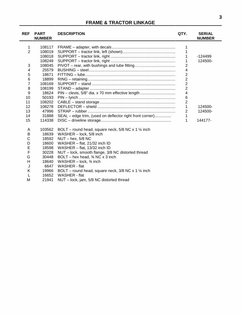
3 FRAME & TRACTOR LINKAGE
REF PART
NUMBER DESCRIPTION QTY. SERIAL
NUMBER
1 108117 FRAME – adapter, with decals.......................................................... 1 2 108019 SUPPORT – tractor link, left (shown)................................................ 1 108018 SUPPORT – tractor link, right ........................................................... 1 -124499 108249 SUPPORT – tractor link, right ........................................................... 1 124500-
3 108045 PIVOT – rear, with bushings and lube fitting..................................... 2 4 25579 BUSHING – steel............................................................................... 4 5 18671 FITTING – lube.................................................................................. 2 6 18899 RING – retaining................................................................................ 2 7 108169 SUPPORT – stand ............................................................................ 2 8 108199 STAND – adapter .............................................................................. 2 9 18624 PIN – clevis, 5/8” dia. x 70 mm effective length ................................ 4
10 50193 PIN – lynch ........................................................................................ 6 11 108202 CABLE – stand storage..................................................................... 2 12 108278 DEFLECTOR – shield ....................................................................... 1 124500- 13 47996 STRAP – rubber ................................................................................ 2 124500- 14 31888 SEAL – edge trim, (used on deflector right front corner)............... 1 15 114338 DISC – driveline storage................................................................ 1 144177-
A 103562 BOLT – round head, square neck, 5/8 NC x 1 ¼ inch B 18639 WASHER – lock, 5/8 inch C 18592 NUT – hex, 5/8 NC D 18600 WASHER – flat, 21/32 inch ID E 18598 WASHER – flat, 13/32 inch ID F 30228 NUT – lock, smooth flange, 3/8 NC distorted thread G 30448 BOLT – hex head, ¾ NC x 3 inch H 18640 WASHER – lock, ¾ inch J 6647 WASHER - flat K 19966 BOLT – round head, square neck, 3/8 NC x 1 ¼ inch L 16652 WASHER - flat M 21941 NUT – lock, jam, 5/8 NC distorted thread
4 HEADER LINKAGE & FLOAT GROUP
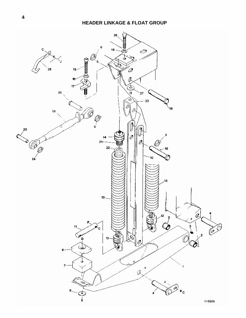
5 HEADER LINKAGE & FLOAT GROUP
REF PART
NUMBER DESCRIPTION QTY. SERIAL
NUMBER
1 108170 LEG – header lower link, includes items 2 & 3.................................. 2 -124499 108276 LEG – header lower link, includes items 2 & 3.................................. 2 124500-
2 1134 SLEEVE – bearing............................................................................. 4 3 18671 FITTING – lube.................................................................................. 2 4 49344 PIN – leg (NOTE: Install pin from inboard side of adapter)............... 4 6 102264 PIN – lynch ........................................................................................ 5 7 42498 PAD – rubber..................................................................................... 2 8 44575 PLATE – pad cover ........................................................................... 2 9 11695 WASHER – flat .................................................................................. 2
10 49214 BAR – spring support ........................................................................ 2 -124499 108263 BAR – spring support ........................................................................ 2 124500-
11 49213 PIN – lower spring anchor ................................................................. 2 12 42691 INSERT – spring, lower ..................................................................... 4 13 42690 SPRING – extension ......................................................................... 4 14 24322 INSERT – spring, upper, with threaded hole..................................... 4 -124499
41358 INSERT – spring, upper, with through hole....................................... 4 124500- 15 41122 BOLT – float spring............................................................................ 4 16 21540 WASHER – hardened........................................................................ 5 17 36837 PIVOT – float spring .......................................................................... 4 18 49341 PIN – float spring ............................................................................... 4 19 108161 JOINT ASSEMBLY – center link ....................................................... 1 20 158635 PIN – clevis, center link, adapter end (was 114126)..................... 1 21 41357 INSERT – spring, inner...................................................................... 4 124500- 22 40766 SPRING – extension, inner ............................................................... 4 124500- 23 108239 SUPPORT – header level ................................................................. 1 124500- 24 50193 PIN – lynch ........................................................................................ 1 25 20312 PIN – clevis, center link, header end................................................. 1 26 108240 BOLT – hex head, ¾ NC x 4 inch, thread full length......................... 1 124500- 27 6647 WASHER – flat .................................................................................. 1 124500- 28 108241 INDICATOR – header float gauge (at R/H spring support) ............... 1 124500-
A 19965 BOLT – round head, square neck, 3/8 NC x 1 inch B 18590 NUT – hex, 3/8 NC (fits in slot of pin bracket) C 30228 NUT – lock, smooth flange, 3/8 NC distorted thread D 30266 BOLT – round head, square neck, 1/2 NC x 3 inch E 21389 NUT – lock, ½ NC nylon insert F 20078 BOLT – hex head, 3/8 NC x 1 ¾ inch G 18603 WASHER – flat, 1-1/16 inch ID H 18593 NUT – hex, ¾ NC J 21975 BOLT – flange head, 3/8 NC x 1 inch K 18598 WASHER – flat, 13/32 inch I.D.

6 HEADER DRIVE HYDRAULICS
With MacDon PUMP
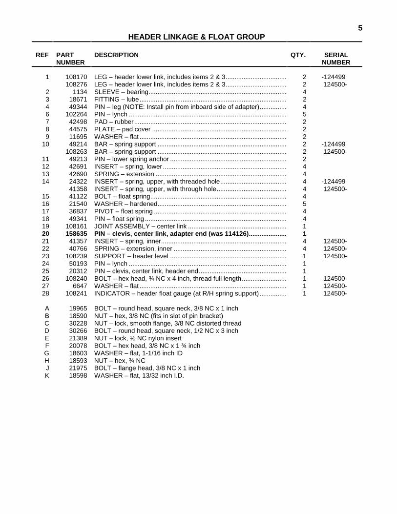
7 HEADER DRIVE HYDRAULICS
With MacDon PUMP
REF PART NUMBER
DESCRIPTION QTY. SERIAL NUMBER
1 108143 ARM – torque, pump ......................................................................... 1 2 REF PUMP/GEARBOX ASSEMBLY, see Pages 10 and 11..................... 1 3 108089 FITTING – adapter, 1 5/8 O-ring x 1 tube ......................................... 1 50222 O-RING – for 1 5/8 fitting
4 108153 FITTING - 90° elbow, 1 5/16 O-ring x ¾ tube ................................... 1 50220 O-RING – for 1 5/16 fitting
5 108062 VALVE – manifold block (was 108504).......................................... 1 24509 KIT – seal, for valve 108062............................................................ 1
7 108517 VALVE – relief, 4000 psi.................................................................... 1 8 50050 FITTING – branch tee, 1 1/16 O-ring* x ¾ tube ................................ 1 9 50097 FITTING – swivel branch tee, 1 1/16 O-ring* x ¾ tube ..................... 1
10 50086 FITTING – swivel run tee, ¾ tube ..................................................... 2 11 21830 FITTING – adapter, 1 1/16 O-ring* x ¾ tube..................................... 2 12 21800 FITTING – elbow, 1 1/16 O-ring* x 1 tube......................................... 1 13 36855 MOTOR – sickle drive ....................................................................... 1
36856 SEAL KIT – for motor 36855 14 30694 FITTING – union tee, 1/2 tube........................................................... 1 15 30282 FITTING - 90° elbow, 9/16 O-ring x 3/8 tube (qty. 1 S.N. –144176) .... 2
50219 O-RING – for 9/16 fitting 16 21857 COUPLER – female, ½ NPT ............................................................. 2
50082 O-RING – for coupler 21857 17 21858 PLUG – dust ...................................................................................... 1 18 50105 CAP – dust ........................................................................................ 2 19 30871 COUPLER – male, 1 1/16 ORB ........................................................ 2 20 50098 FITTING – 45° elbow, 1 1/16 O-ring* x ¾ tube ................................. 2 21 21836 FITTING – adapter, ¾ tube x ¾ NPT ................................................ 1 22 21842 VALVE – check.................................................................................. 1 23 108073 FITTING – adapter, ¾ NPT x ¾ tube swivel female ......................... 1 24 108137 LINE – hydraulic ................................................................................ 1 25 108087 HOSE – pump suction & pressure .................................................... 2 26 108091 HOSE – sickle drive motor pressure & return ................................... 2 -144176 27 108139 HOSE – sickle drive motor case drain............................................... 1 -144176 28 38747 HOSE – case drain return to tractor .................................................. 1 29 108146 HOSE – tractor to valve “P” port........................................................ 1 30 108145 HOSE – check valve to tractor return................................................ 1 31 45122 HOSE – pump case drain NOTE: For Adapters without Header- ... 1
Lower Control Group, hose Item 31 connects to tee Item 14. Tee Item 63 is not used.
32 45542 VALVE – header drive, includes items 33 to 38................................ 1 45101 SEAL KIT – repairs one valve cartridge
33 45107 VALVE – N.C..................................................................................... 1 34 45108 VALVE – P.D., relief, header drive block (stamped I.D. #2155) ....... 1 35 45109 FLOW CONTROL.............................................................................. 2
45123 SETSCREW – for flow control 45109 36 45110 VALVE – shuttle ................................................................................ 1 37 45111 VALVE – regulator............................................................................. 1 38 45104 COIL – DS, 12 VDC........................................................................... 1 39 30695 FITTING – adapter, 7/8 O-ring x 5/8 tube 1
44210 O-RING – for 7/8 fitting 40 33424 HOSE – valve “C” port to header conveyor pressure........................ 1 41 21855 COUPLER – male, ½ NPT ................................................................ 2 42 135011 FITTING – plug, #2 ORB.................................................................. 1 - 150558
100577 FITTING – plug, 3/8 ORB, hex socket ............................................ 1 150559 - * 30971 O-RING – for 1 1/16 fitting

8 HEADER DRIVE HYDRAULICS
With MacDon PUMP
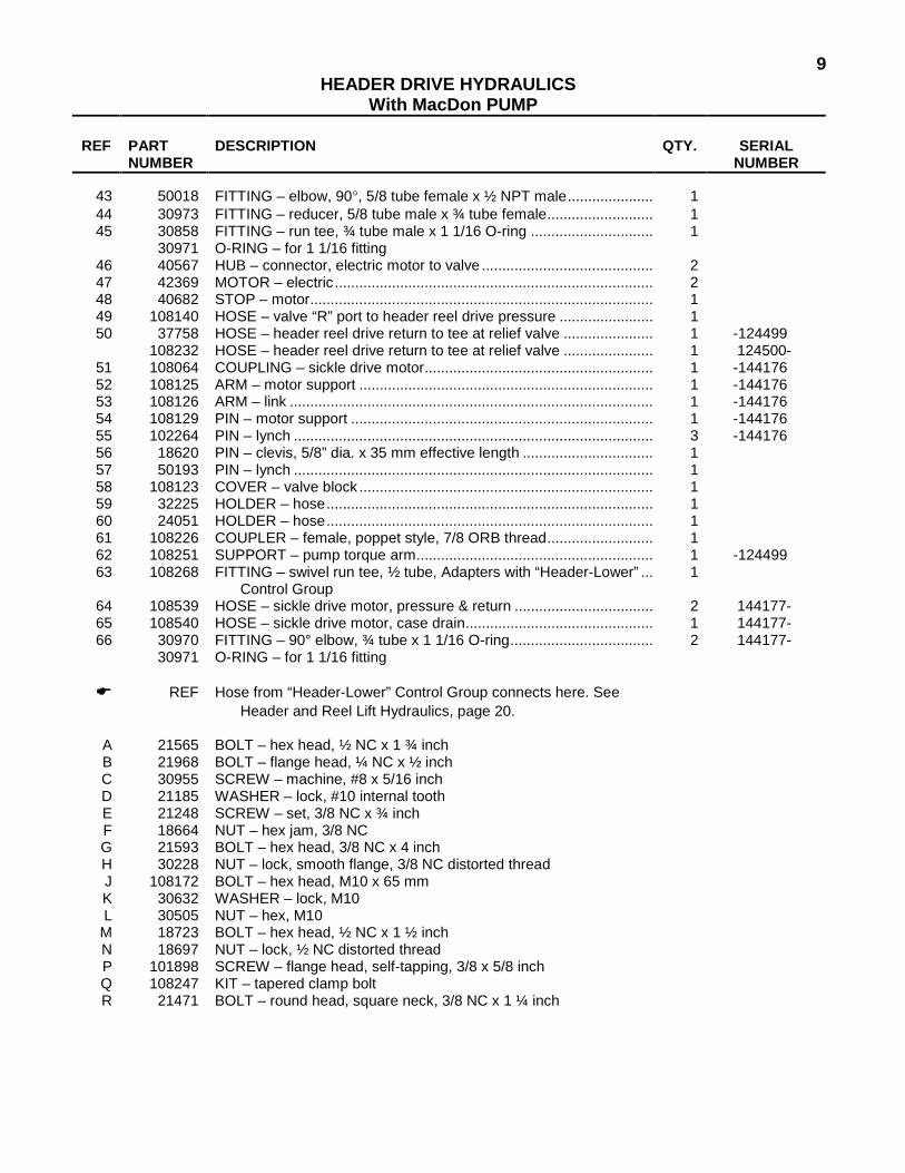
9 HEADER DRIVE HYDRAULICS
With MacDon PUMP
REF PART NUMBER
DESCRIPTION QTY. SERIAL NUMBER
43 50018 FITTING – elbow, 90°, 5/8 tube female x ½ NPT male..................... 1 44 30973 FITTING – reducer, 5/8 tube male x ¾ tube female.......................... 1 45 30858 FITTING – run tee, ¾ tube male x 1 1/16 O-ring .............................. 1
30971 O-RING – for 1 1/16 fitting 46 40567 HUB – connector, electric motor to valve .......................................... 2 47 42369 MOTOR – electric.............................................................................. 2 48 40682 STOP – motor.................................................................................... 1 49 108140 HOSE – valve “R” port to header reel drive pressure ....................... 1 50 37758 HOSE – header reel drive return to tee at relief valve ...................... 1 -124499
108232 HOSE – header reel drive return to tee at relief valve ...................... 1 124500- 51 108064 COUPLING – sickle drive motor........................................................ 1 -144176 52 108125 ARM – motor support ........................................................................ 1 -144176 53 108126 ARM – link ......................................................................................... 1 -144176 54 108129 PIN – motor support .......................................................................... 1 -144176 55 102264 PIN – lynch ........................................................................................ 3 -144176 56 18620 PIN – clevis, 5/8” dia. x 35 mm effective length ................................ 1 57 50193 PIN – lynch ........................................................................................ 1 58 108123 COVER – valve block ........................................................................ 1 59 32225 HOLDER – hose................................................................................ 1 60 24051 HOLDER – hose................................................................................ 1 61 108226 COUPLER – female, poppet style, 7/8 ORB thread.......................... 1 62 108251 SUPPORT – pump torque arm.......................................................... 1 -124499 63 108268 FITTING – swivel run tee, ½ tube, Adapters with “Header-Lower” ... 1
Control Group 64 108539 HOSE – sickle drive motor, pressure & return .................................. 2 144177- 65 108540 HOSE – sickle drive motor, case drain.............................................. 1 144177- 66 30970 FITTING – 90° elbow, ¾ tube x 1 1/16 O-ring................................... 2 144177-
30971 O-RING – for 1 1/16 fitting
� REF Hose from “Header-Lower” Control Group connects here. See Header and Reel Lift Hydraulics, page 20.
A 21565 BOLT – hex head, ½ NC x 1 ¾ inch B 21968 BOLT – flange head, ¼ NC x ½ inch C 30955 SCREW – machine, #8 x 5/16 inch D 21185 WASHER – lock, #10 internal tooth E 21248 SCREW – set, 3/8 NC x ¾ inch F 18664 NUT – hex jam, 3/8 NC G 21593 BOLT – hex head, 3/8 NC x 4 inch H 30228 NUT – lock, smooth flange, 3/8 NC distorted thread J 108172 BOLT – hex head, M10 x 65 mm K 30632 WASHER – lock, M10 L 30505 NUT – hex, M10 M 18723 BOLT – hex head, ½ NC x 1 ½ inch N 18697 NUT – lock, ½ NC distorted thread P 101898 SCREW – flange head, self-tapping, 3/8 x 5/8 inch Q 108247 KIT – tapered clamp bolt R 21471 BOLT – round head, square neck, 3/8 NC x 1 ¼ inch

10MacDon PUMP/GEARBOX ASSEMBLY

11MacDon PUMP/GEARBOX ASSEMBLY
REF PART
NUMBER DESCRIPTION QTY. SERIAL
NUMBER
1 108148 PUMP/GEARBOX - 1000 RPM, incl. items 2, 20 to 22, and 30...... 1 PISTON PUMP COMPONENTS
2 108149 PUMP - piston, 1000 RPM - includes items 3 to 17 .......................... 1 3 * 18900 RING - retaining, outer ...................................................................... 1 4 * 30046 SEAL – shaft...................................................................................... 1 5 WASHER - flat, 1-19/32 x 2 x 5/64 inch ............................................ 1 6 * 30144 RING – retaining................................................................................ 2 7 30140 BEARING RACE – thrust .................................................................. 2 8 30141 BEARING – thrust ............................................................................. 1 9 SHAFT – drive ................................................................................... 1
10 21420 BEARING - needle, housing.............................................................. 1 11 HOUSING ASSEMBLY 1000 RPM (2.01 cu.in./rev. displacement).. 1 12 INSERT - cam plate........................................................................... 1 13 ROTATING ASSEMBLY.................................................................... 1 14 * 30045 O-RING - housing to back plate ........................................................ 1 15 ROLL PIN .......................................................................................... 1 16 BEARING - needle, back plate (Torrington B-1412) ......................... 1 17 BACK PLATE ASSEMBLY................................................................ 1
* 30247 SEAL KIT - for piston pump, includes items marked * CONNECTING COMPONENTS
20 50100 SUN GEAR - 1000 RPM, pump to gear box connection................... 1 21 5924 RING - retaining, sun gear ................................................................ 2 22 30045 O-RING - pump to gear box connection............................................ 1
GEARBOX COMPONENTS
30 36892 GEARBOX - 1000 RPM - includes items 31 to 41 ..........................1 31 + RING - retaining, internal 3 inch 32 + SEAL - shaft 33 PLATE - front 34 + O-RING - housing to front plate and housing to adapter plate 35 + RING - retaining, external 2 5/32 inch 36 50208 BEARING - carrier 37 + RING - retaining, internal 3 9/16 inch 38 + RING - lock 39 36943 CARRIER ASSEMBLY - 1000 RPM 40 HOUSING 41 PLATE - adapter
+ 36854 SEAL KIT - for gearbox, includes items marked +
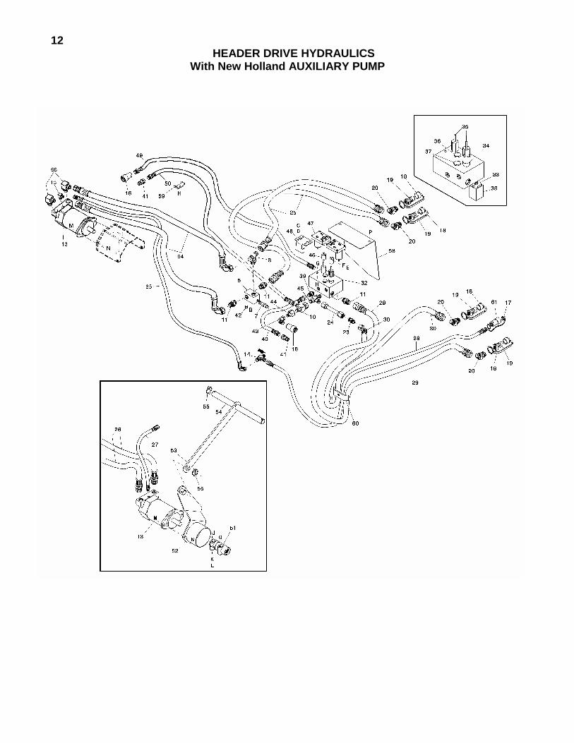
12HEADER DRIVE HYDRAULICS
With New Holland AUXILIARY PUMP

13HEADER DRIVE HYDRAULICS
With New Holland AUXILIARY PUMP
REF PART NUMBER
DESCRIPTION QTY. SERIAL NUMBER
5 108062 VALVE – manifold block (was 108504) ............................................... 1
24509 KIT – seal, for valve block 108062....................................................... 1 7 108517 VALVE – relief, 4000 psi......................................................................... 1 8 50050 FITTING – branch tee, 1 1/16 O-ring* x ¾ tube ..................................... 1
10 50086 FITTING – swivel run tee, ¾ tube........................................................... 1 11 21830 FITTING – adapter, 1 1/16 O-ring* x ¾ tube .......................................... 3 13 36855 MOTOR – sickle drive ............................................................................ 1
36856 SEAL KIT – for motor 36855 14 30694 FITTING – union tee, 1/2 tube................................................................ 1 15 30282 FITTING - 90° elbow, 9/16 O-ring x 3/8 tube.......................................... 1 144177-
50219 O-RING – for 9/16 fitting 16 21857 COUPLER – female, ½ NPT .................................................................. 2
50082 O-RING – for coupler 21857 17 21858 PLUG – dust ........................................................................................... 1 18 50105 CAP – dust ............................................................................................. 4 19 30871 COUPLER – male, 1 1/16 ORB.............................................................. 4 20 50098 FITTING – 45° elbow, 1 1/16 O-ring* x ¾ tube....................................... 4 23 30376 FITTING – union, ¾ tube........................................................................ 1 24 108137 LINE – hydraulic ..................................................................................... 1 25 108235 HOSE – suction & pressure from NH auxiliary pump ............................. 2 26 108091 HOSE – sickle drive motor pressure & return......................................... 2 -144176 27 108139 HOSE – sickle drive motor case drain.................................................... 1 -144176 28 38747 HOSE – case drain return to tractor ....................................................... 1 29 108146 HOSE – tractor to valve “P” port............................................................. 1 30 108145 HOSE – check valve to tractor return ..................................................... 1 32 45542 VALVE – header drive, includes items 33 to 38 ..................................... 1
45101 SEAL KIT – repairs one valve cartridge 33 45107 VALVE – N.C.......................................................................................... 1 34 45108 VALVE – P.D., relief, header drive block (stamped I.D. #2155) ............. 1 35 45109 FLOW CONTROL................................................................................... 2
45123 SETSCREW – for flow control 45109 36 45110 VALVE – shuttle ..................................................................................... 1 37 45111 VALVE – regulator.................................................................................. 1 38 45104 COIL – DS, 12 VDC................................................................................ 1 39 30695 FITTING – adapter, 7/8 O-ring x 5/8 tube 1
44210 O-RING – for 7/8 fitting 40 33424 HOSE – valve “C” port to header conveyor pressure ............................. 1 41 21855 COUPLER – male, ½ NPT ..................................................................... 2 42 135011 FITTING – plug, #2 ORB ....................................................................... 1 - 150558
100577 FITTING – plug, 3/8 ORB, hex socket ................................................. 1 150559 - 43 50018 FITTING – elbow, 90°, 5/8 tube female x ½ NPT male .......................... 1 44 30973 FITTING – reducer, 5/8 tube male x ¾ tube female ............................... 1 45 30858 FITTING – run tee, ¾ tube male x 1 1/16 O-ring* .................................. 1 46 40567 HUB – connector, electric motor to valve ............................................... 2 47 42369 MOTOR – electric................................................................................... 2 48 40682 STOP – motor......................................................................................... 1 49 108140 HOSE – valve “R” port to header reel drive pressure............................. 1 50 108232 HOSE – header reel drive return to tee at relief valve............................ 1 51 108064 COUPLING – sickle drive motor............................................................. 1 -144176 52 108125 ARM – motor support ............................................................................. 1 -144176 53 108126 ARM – link .............................................................................................. 1 -144176 54 108129 PIN – motor support ............................................................................... 1 -144176 55 102264 PIN – lynch ............................................................................................. 3 -144176 � REF Hose from “Header-Lower” Control Group connects here. See
Header and Reel Lift Hydraulics, page 20. * 30971 O-RING – for 1 1/16 fitting

14HEADER DRIVE HYDRAULICS
With New Holland AUXILIARY PUMP

15HEADER DRIVE HYDRAULICS
With New Holland AUXILIARY PUMP
REF PART NUMBER
DESCRIPTION QTY. SERIAL NUMBER
56 18620 PIN – clevis, 5/8” dia. x 35 mm effective length ................................ 1 57 50193 PIN – lynch ........................................................................................ 1 58 108123 COVER – valve block ........................................................................ 1 59 32225 HOLDER – hose................................................................................ 1 60 24051 HOLDER – hose................................................................................ 1 61 108226 COUPLER – female, poppet style, 7/8 ORB thread.......................... 1 64 108539 HOSE – sickle drive motor, pressure & return .................................. 2 144177- 65 108540 HOSE – sickle drive motor, case drain.............................................. 1 144177- 66 30970 FITTING – 90° elbow, ¾ tube x 1 1/16 O-ring................................... 2 144177-
30971 O-RING – for 1 1/16 fitting
B 21968 BOLT – flange head, ¼ NC x ½ inch C 30955 SCREW – machine, #8 x 5/16 inch D 21185 WASHER – lock, #10 internal tooth E 21248 SCREW – set, 3/8 NC x ¾ inch F 18664 NUT – hex jam, 3/8 NC G 21593 BOLT – hex head, 3/8 NC x 4 inch H 30228 NUT – lock, smooth flange, 3/8 NC distorted thread J 108172 BOLT – hex head, M10 x 65 mm K 30632 WASHER – lock, M10 L 30505 NUT – hex, M10 M 18723 BOLT – hex head, ½ NC x 1 ½ inch N 18697 NUT – lock, ½ NC distorted thread P 101898 SCREW – flange head, self-tapping, 3/8 x 5/8 inch Q 108247 KIT – tapered clamp bolt

16HEADER DRIVELINE
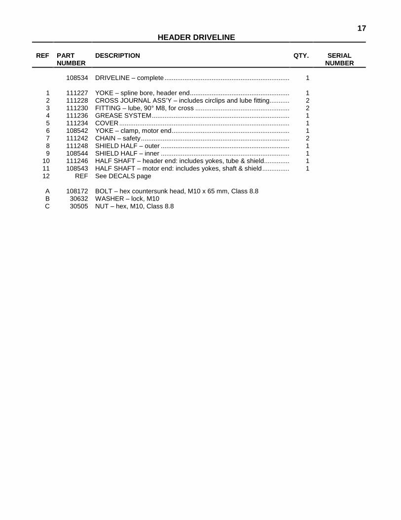
17HEADER DRIVELINE
REF PART
NUMBER DESCRIPTION QTY. SERIAL
NUMBER 108534 DRIVELINE – complete ..................................................................... 1
1 111227 YOKE – spline bore, header end....................................................... 1 2 111228 CROSS JOURNAL ASS’Y – includes circlips and lube fitting........... 2 3 111230 FITTING – lube, 90° M8, for cross .................................................... 2 4 111236 GREASE SYSTEM............................................................................ 1 5 111234 COVER.............................................................................................. 1 6 108542 YOKE – clamp, motor end................................................................. 1 7 111242 CHAIN – safety.................................................................................. 2 8 111248 SHIELD HALF – outer ....................................................................... 1 9 108544 SHIELD HALF – inner ....................................................................... 1
10 111246 HALF SHAFT – header end: includes yokes, tube & shield.............. 1 11 108543 HALF SHAFT – motor end: includes yokes, shaft & shield............... 1 12 REF See DECALS page
A 108172 BOLT – hex countersunk head, M10 x 65 mm, Class 8.8 B 30632 WASHER – lock, M10 C 30505 NUT – hex, M10, Class 8.8

18HEADER & REEL LIFT HYDRAULICS
Serial No. 124499 and below
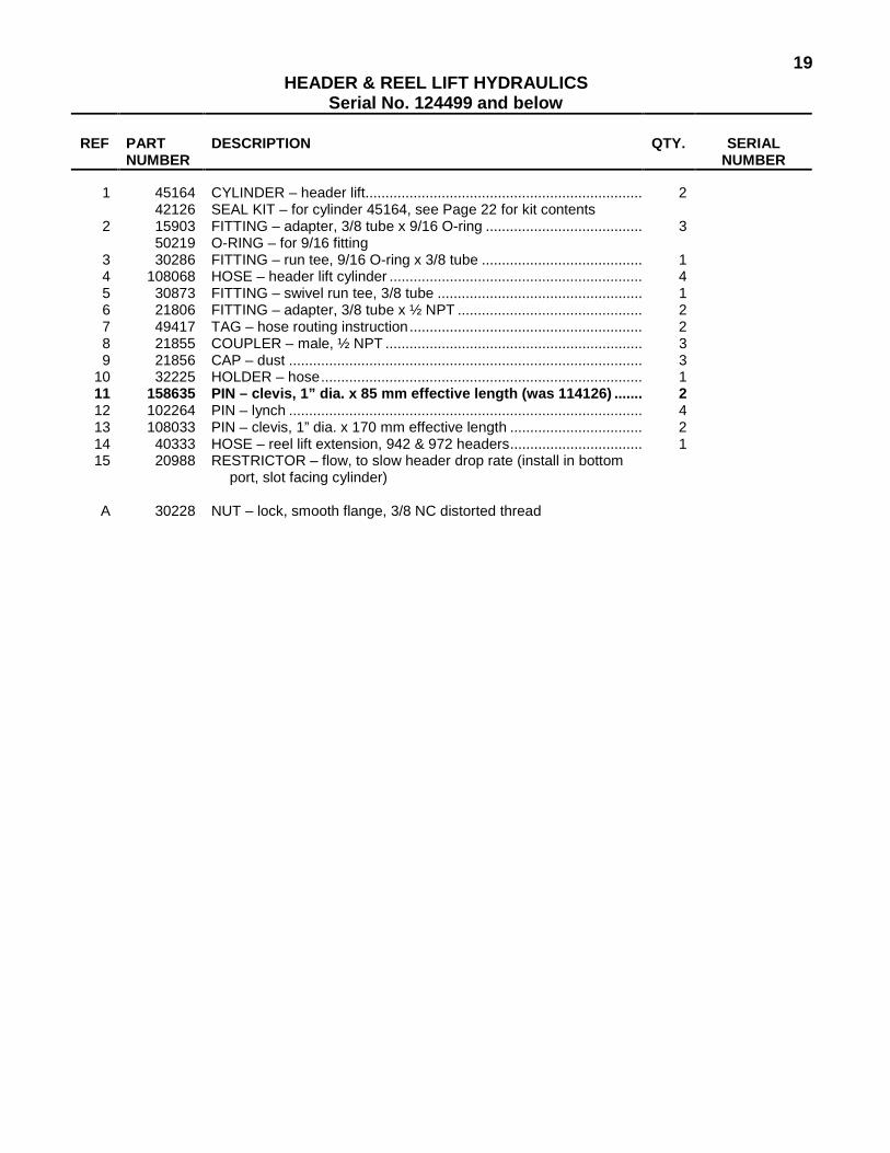
19HEADER & REEL LIFT HYDRAULICS
Serial No. 124499 and below
REF PART NUMBER
DESCRIPTION QTY. SERIAL NUMBER
1 45164 CYLINDER – header lift..................................................................... 2 42126 SEAL KIT – for cylinder 45164, see Page 22 for kit contents
2 15903 FITTING – adapter, 3/8 tube x 9/16 O-ring ....................................... 3 50219 O-RING – for 9/16 fitting
3 30286 FITTING – run tee, 9/16 O-ring x 3/8 tube ........................................ 1 4 108068 HOSE – header lift cylinder ............................................................... 4 5 30873 FITTING – swivel run tee, 3/8 tube ................................................... 1 6 21806 FITTING – adapter, 3/8 tube x ½ NPT .............................................. 2 7 49417 TAG – hose routing instruction.......................................................... 2 8 21855 COUPLER – male, ½ NPT ................................................................ 3 9 21856 CAP – dust ........................................................................................ 3
10 32225 HOLDER – hose................................................................................ 1 11 158635 PIN – clevis, 1” dia. x 85 mm effective length (was 114126) ....... 2 12 102264 PIN – lynch ........................................................................................ 4 13 108033 PIN – clevis, 1” dia. x 170 mm effective length ................................. 2 14 40333 HOSE – reel lift extension, 942 & 972 headers................................. 1 15 20988 RESTRICTOR – flow, to slow header drop rate (install in bottom
port, slot facing cylinder)
A 30228 NUT – lock, smooth flange, 3/8 NC distorted thread
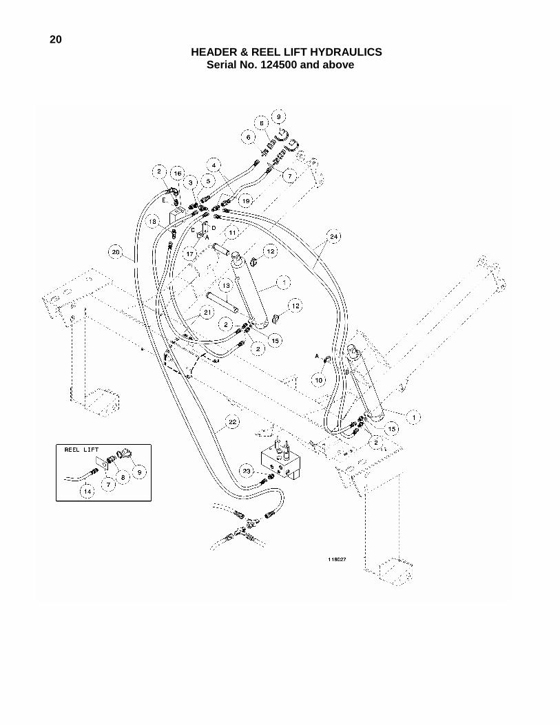
20HEADER & REEL LIFT HYDRAULICS
Serial No. 124500 and above

21HEADER & REEL LIFT HYDRAULICS
Serial No. 124500 and above
REF PART NUMBER
DESCRIPTION QTY. SERIAL NUMBER
1 45164 CYLINDER – header lift..................................................................... 2 42126 SEAL KIT – for cylinder 45164, see Page 22 for kit contents
2 15903 FITTING – adapter, 3/8 tube x 9/16 O-ring ....................................... 5 50219 O-RING – for 9/16 fitting
3 30286 FITTING – run tee, 9/16 O-ring x 3/8 tube ........................................ 1 4 31813 HOSE – tractor to valve..................................................................... 2 5 30873 FITTING – swivel run tee, 3/8 tube ................................................... 1 6 21806 FITTING – adapter, 3/8 tube x ½ NPT .............................................. 2 7 49417 TAG – hose routing instruction.......................................................... 2 8 21855 COUPLER – male, ½ NPT ................................................................ 3 9 21856 CAP – dust ........................................................................................ 3
10 43848 HOLDER – hose................................................................................ 1 11 158635 PIN – clevis, 1” dia. x 85 mm effective length (was 114126) ....... 2 12 102264 PIN – lynch ........................................................................................ 4 13 108033 PIN – clevis, 1” dia. x 170 mm effective length ................................. 2 14 40333 HOSE – reel lift extension, 942 & 972 headers................................. 1 15 20988 RESTRICTOR – flow, to slow header drop rate (install in bottom
port, slot facing cylinder) 16 108236 VALVE – check.................................................................................. 1 17 108271 SUPPORT – valve............................................................................. 1 18 30282 FITTING – elbow, 90º - 3/8 tube x 9/16 O-ring.................................. 1
50219 O-RING – for 9/16 fitting 19 7603 FITTING – union tee, 3/8 tube........................................................... 1 20 31816 HOSE – check valve to tee. See � on pages 6 and 12 for 1
connection to Header Drive hydraulic circuit 21 45135 HOSE – valve to R/H lift cylinder....................................................... 2 22 45131 HOSE – check valve to header drive valve ....................................... 1 23 21804 FITTING – adapter, 3/8 tube x ¾ O-ring
44209 O-RING – for ¾ fitting 24 31802 HOSE – valve to L/H lift cylinder ....................................................... 2
A 30228 NUT – lock, smooth flange, 3/8 NC distorted thread B 19965 BOLT – round head, square neck, 3/8 NC x 1 inch C 19966 BOLT – round head, square neck, 3/8 NC x 1 ¼ inch D 21482 BOLT – round head, square neck, 5/16 NC x 2 ¼ inch E 30280 NUT – lock, smooth flange, 5/16 NC distorted thread
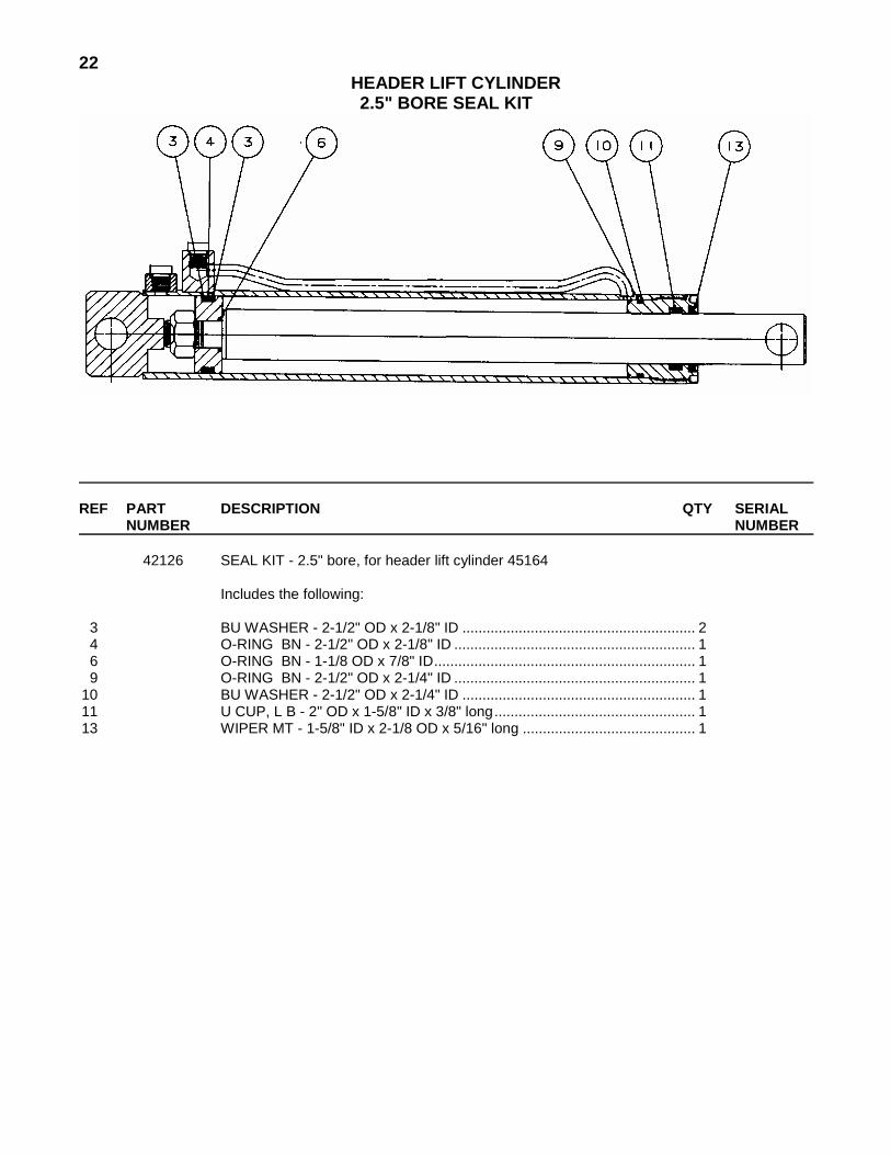
22HEADER LIFT CYLINDER 2.5" BORE SEAL KIT
REF PART DESCRIPTION QTY SERIAL
NUMBER NUMBER 42126 SEAL KIT - 2.5" bore, for header lift cylinder 45164 Includes the following: 3 BU WASHER - 2-1/2" OD x 2-1/8" ID .......................................................... 2 4 O-RING BN - 2-1/2" OD x 2-1/8" ID ............................................................ 1 6 O-RING BN - 1-1/8 OD x 7/8" ID................................................................. 1 9 O-RING BN - 2-1/2" OD x 2-1/4" ID ............................................................ 1 10 BU WASHER - 2-1/2" OD x 2-1/4" ID .......................................................... 1 11 U CUP, L B - 2" OD x 1-5/8" ID x 3/8" long.................................................. 1 13 WIPER MT - 1-5/8" ID x 2-1/8 OD x 5/16" long ........................................... 1

23ELECTRICAL
REF PART NUMBER
DESCRIPTION QTY. SERIAL NUMBER
1 108077 HARNESS – wiring, adapter section ................................................. 1 30710 PLUG – 7-pole, included with harness 108077
2 108523 HARNESS – wiring, switch panel section (was 108267) .................. 1 3 108081 PANEL – switch, with decal............................................................... 1 -131619 108284 PANEL – switch, with decal............................................................... 1 131620-
4 42256 SWITCH – reel and draper speed ..................................................... 2 5 113543 SWITCH – deck shift – Hyd. Shift Headers only (was 42257) .......... 1 -131619 109063 SWITCH – deck shift – Hyd. Shift Headers only ............................... 1 131620-
9 108191 COVER – switch panel ...................................................................... 1 10 39272 HOLDER – harness........................................................................... 1 11 108192 MOUNT – switch panel, TV140 tractor only...................................... 1 12 108158 SUPPORT – headlight, 9030 tractor only.......................................... 2
A 42292 SCREW – self-tapping, Type A, hex washer head, #10 x ½ inch B 21449 BOLT – serrated flange head, ½ NC x 1 inch C 50186 NUT – lock, smooth flange, ½ NC distorted thread D 21926 BOLT – round head, square neck, ¼ NC x ½ inch E 21455 NUT – serrated flange lock, ¼ NC

24HAY CONDITIONER FORMING SHIELDS
& MOUNTING GROUP
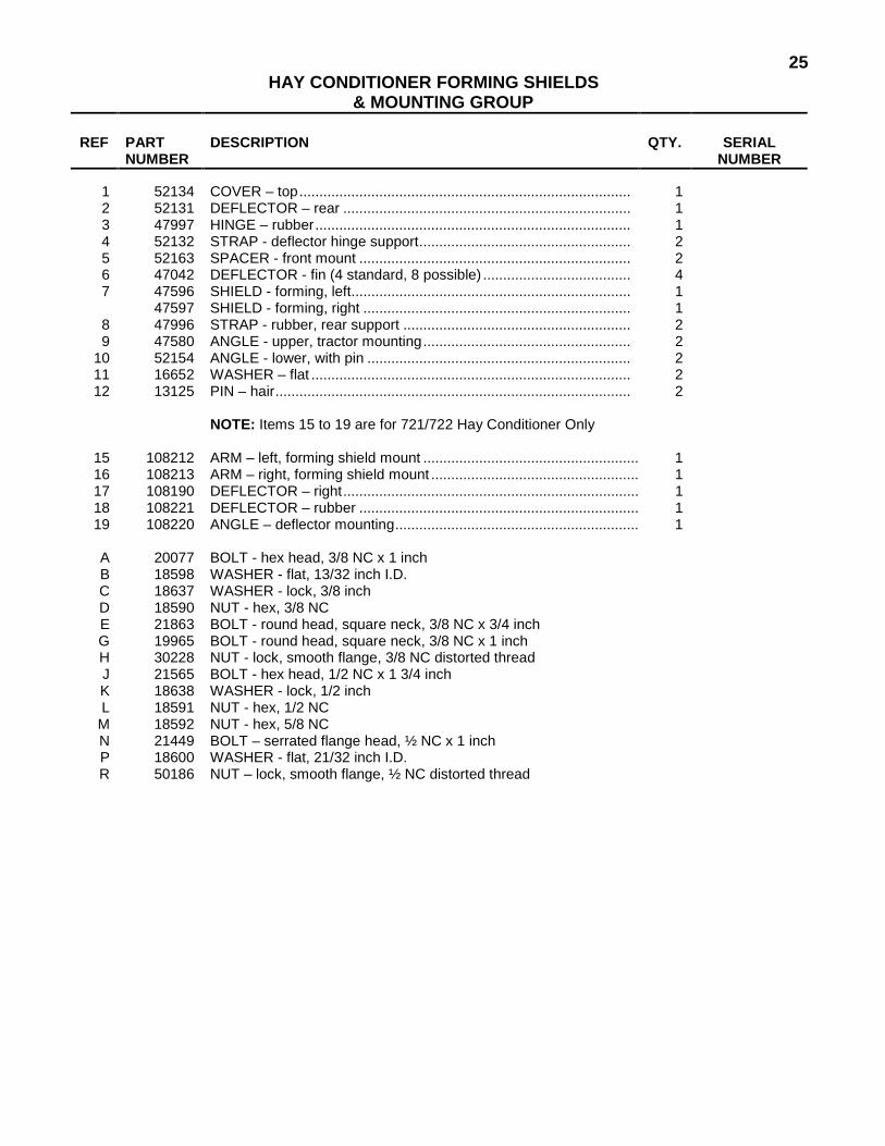
25HAY CONDITIONER FORMING SHIELDS
& MOUNTING GROUP
REF PART NUMBER
DESCRIPTION QTY. SERIAL NUMBER
1 52134 COVER – top................................................................................... 1 2 52131 DEFLECTOR – rear ........................................................................ 1 3 47997 HINGE – rubber............................................................................... 1 4 52132 STRAP - deflector hinge support..................................................... 2 5 52163 SPACER - front mount .................................................................... 2 6 47042 DEFLECTOR - fin (4 standard, 8 possible) ..................................... 4 7 47596 SHIELD - forming, left...................................................................... 1 47597 SHIELD - forming, right ................................................................... 1
8 47996 STRAP - rubber, rear support ......................................................... 2 9 47580 ANGLE - upper, tractor mounting.................................................... 2
10 52154 ANGLE - lower, with pin .................................................................. 2 11 16652 WASHER – flat ................................................................................ 2 12 13125 PIN – hair......................................................................................... 2
NOTE: Items 15 to 19 are for 721/722 Hay Conditioner Only
15 108212 ARM – left, forming shield mount ...................................................... 1 16 108213 ARM – right, forming shield mount .................................................... 1 17 108190 DEFLECTOR – right.......................................................................... 1 18 108221 DEFLECTOR – rubber ...................................................................... 1 19 108220 ANGLE – deflector mounting............................................................. 1
A 20077 BOLT - hex head, 3/8 NC x 1 inch B 18598 WASHER - flat, 13/32 inch I.D. C 18637 WASHER - lock, 3/8 inch D 18590 NUT - hex, 3/8 NC E 21863 BOLT - round head, square neck, 3/8 NC x 3/4 inch G 19965 BOLT - round head, square neck, 3/8 NC x 1 inch H 30228 NUT - lock, smooth flange, 3/8 NC distorted thread J 21565 BOLT - hex head, 1/2 NC x 1 3/4 inch K 18638 WASHER - lock, 1/2 inch L 18591 NUT - hex, 1/2 NC M 18592 NUT - hex, 5/8 NC N 21449 BOLT – serrated flange head, ½ NC x 1 inch P 18600 WASHER - flat, 21/32 inch I.D. R 50186 NUT – lock, smooth flange, ½ NC distorted thread
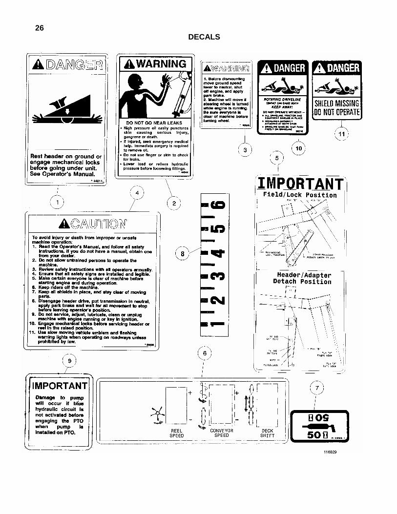
26 DECALS

27DECALS
REF PART
NUMBER DESCRIPTION QTY. SERIAL
NUMBER
1 44611 DECAL – Danger: Engage Mechanical Locks .................................. 2 2 44944 DECAL – Warning: Hydraulic Oil Leaks ............................................ 1 3 40555 DECAL – Warning: Controls to Neutral ............................................. 1 4 32009 DECAL – Caution: General Safety .................................................... 1 5 108177 DECAL – Important: Upper Float Pin Positions (was 49240)............ 1 6 108283 DECAL – Switch Panel (was 108084)............................................... 1 7 23165 DECAL – 50 Hour Grease................................................................. 4 8 44627 DECAL – Gauge, Header Float ......................................................... 1 9 108282 DECAL – Important: Pump Damage ................................................. 1
10 30316 DECAL – Danger: Rotating Driveline ................................................ 1 11 36651 DECAL – Danger: Driveline Shield Missing ...................................... 1

NUMERICAL LIST
PART NO. PAGE PART NO. PAGE PART NO. PAGE PART NO. PAGE
28
1134 5 5924 11 6647 5 7603 21
11695 5 13125 25 15903 19 15903 21 16652 25 18620 9 18620 15 18624 3 18671 3 18671 5 18899 3 18900 11 20312 5 20988 19 20988 21 21420 11 21540 5 21800 7 21804 21 21806 19 21806 21 21830 7 21830 13 21836 7 21842 7 21855 7 21855 13 21855 19 21855 21 21856 19 21856 21 21857 7 21857 13 21858 7 21858 13 23165 27 24051 9 24051 15 24322 5 24509 7 24509 13 25579 3 30045 11 30045 11 30046 11 30140 11 30141 11 30144 11 30247 11
30282 7 30282 13 30282 21 30286 19 30286 21 30316 27 30376 13 30694 7 30694 13 30695 7 30695 13 30710 23 30858 9 30858 13 30871 7 30871 13 30873 19 30873 21 30970 9 30970 15 30971 7 30971 9 30971 9 30971 13 30971 15 30973 9 30973 13 31802 21 31813 21 31816 21 31888 3 32009 27 32225 9 32225 15 32225 19 33424 7 33424 13 36651 27 36837 5 36854 11 36855 7 36855 13 36856 7 36856 13 36892 11 36943 11 37758 9 38747 7 38747 13 39272 23 40333 19 40333 21 40555 27
40567 9 40567 13 40682 9 40682 13 40766 5 41122 5 41357 5 41358 5 42126 19 42126 21 42126 22 42256 23 42369 9 42369 13 42498 5 42690 5 42691 5 43848 21 44209 21 44210 7 44210 13 44575 5 44611 27 44627 27 44944 27 45101 7 45101 13 45104 7 45104 13 45107 7 45107 13 45108 7 45108 13 45109 7 45109 13 45110 7 45110 13 45111 7 45111 13 45122 7 45123 7 45123 13 45131 21 45135 21 45164 19 45164 21 45542 7 45542 13 47042 25 47580 25 47596 25 47597 25 47996 3
47996 25 47997 25 49213 5 49214 5 49341 5 49344 5 49417 19 49417 21 50018 9 50018 13 50050 7 50050 13 50082 7 50082 13 50086 7 50086 13 50097 7 50098 7 50098 13 50100 11 50105 7 50105 13 50193 3 50193 5 50193 9 50193 15 50208 11 50219 7 50219 13 50219 19 50219 21 50219 21 50220 7 50222 7 52131 25 52132 25 52134 25 52154 25 52163 25
100577 7 100577 13 102264 5 102264 9 102264 13 102264 19 102264 21 108018 3 108019 3 108033 19 108033 21 108045 3 108062 7 108062 13

NUMERICAL LIST
PART NO. PAGE PART NO. PAGE PART NO. PAGE PART NO. PAGE
29
108064 9 108064 13 108068 19 108073 7 108077 23 108081 23 108087 7 108089 7 108091 7 108091 13 108117 3 108123 9 108123 15 108125 9 108125 13 108126 9 108126 13 108129 9 108129 13 108137 7 108137 13 108139 7 108139 13 108140 9 108140 13 108143 7 108145 7 108145 13 108146 7 108146 13 108148 11 108149 11 108153 7 108158 23 108161 5 108169 3 108170 5 108177 27 108190 25 108191 23 108192 23 108199 3 108202 3 108212 25 108213 25 108220 25 108221 25 108226 9 108226 15 108232 9 108232 13 108235 13 108236 21
108239 5 108240 5 108241 5 108249 3 108251 9 108263 5 108268 9 108271 21 108276 5 108278 3 108282 27 108283 27 108284 23 108517 7 108517 13 108523 23 108534 17 108539 9 108539 15 108540 9 108540 15 108542 17 108543 17 108544 17 109063 23 111227 17 111228 17 111230 17 111234 17 111236 17 111242 17 111246 17 111248 17 113543 23 114338 3 135011 7 135011 13 158635 5 158635 19 158635 21