1 m-6017-a504v-a54sc electronic throttle crate...
TRANSCRIPT
1 M-6017-A504V-A54SC Electronic Throttle Crate Engine Controls Pack INSTRUCTION SHEET
NO PART OF THIS DOCUMENT MAY BE REPRODUCED WITHOUT PRIOR AGREEMENT AND WRITTEN PERMISSION OF FORD RACING PERFORMANCE PARTS
Techline 1-800-367-3788 Page 1 of 16 IS-1850-0213
Factory Ford shop manuals are available from Helm Publications, 1-800-782-4356
Please visit www.fordracingparts.com for the most current instruction and warranty information.
! ! ! PLEASE READ ALL OF THE FOLLOWING INSTRUCTIONS CAREFULLY PRIOR TO INSTALLATION.
AT ANY TIME YOU DO NOT UNDERSTAND THE INSTRUCTIONS, PLEASE CALL THE FORD RACING TECHLINE AT 1-800-367-3788 ! ! !
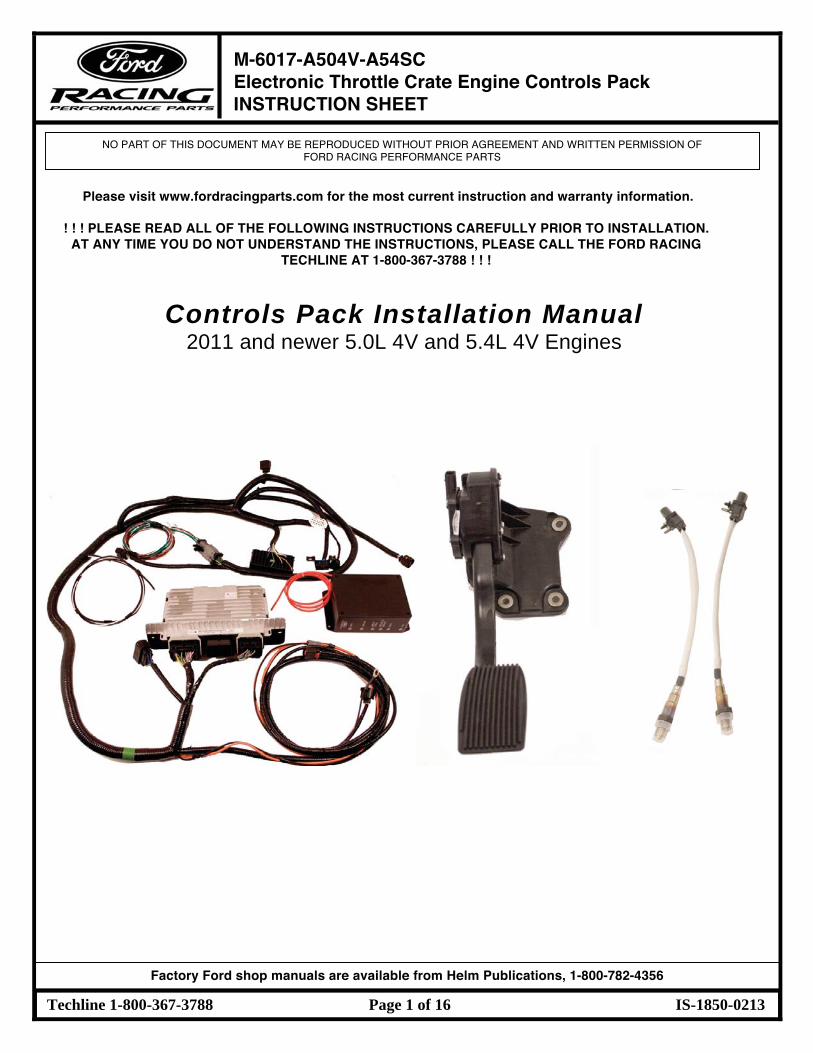
Controls Pack Installation Manual
2011 and newer 5.0L 4V and 5.4L 4V Engines
1 M-6017-A504V-A54SC Electronic Throttle Crate Engine Controls Pack INSTRUCTION SHEET
NO PART OF THIS DOCUMENT MAY BE REPRODUCED WITHOUT PRIOR AGREEMENT AND WRITTEN PERMISSION OF FORD RACING PERFORMANCE PARTS
Techline 1-800-367-3788 Page 2 of 16 IS-1850-0213
Factory Ford shop manuals are available from Helm Publications, 1-800-782-4356
TABLE OF CONTENTS
Section Topic Page
1.0 Introduction……………………………………………………………………………… 2
2.0 Overview………………………………………………………………………………… 3
3.0 Included Components…………………………………………………………………. 3-5
4.0 Tools Required………………………………………………………………………… 6
5.0 Pre-Installation of Harness and Parts………………………………………………... 6
6.0 Harness Wire Colors and Connector Locations…………………………………… 7-9
7.0 Harness Installation…………………………………………………………………… 10
8.0 Blunt Lead Wiring Connections………………………………………………….. 11
9.0 Fuel System…………………………………………………………………………… 12
10.0 PDB Installation………………………………………………………………………… 13
11.0 Initial Start Up…………………………………………………………………………... 13
12.0 PCM Connector Face and Usage Charts…………………………………………… 14-16
1.0 INTRODUCTION
This kit was developed by Ford Racing to allow performance enthusiasts to easily install todayʼs modern muscle into street rods from yesterday. We have developed this system to take the complexity and mystery out of installing a Mustang Electronic Throttle Control (ETC) engine into your vehicle. Important Note for 5.4L Crate Engine Applications: The FR wiring harness in this kit must interface to a production engine harness for model years 2011 and newer. The FR wiring harness will not interface to a 5.4L engine harness for 2007-2010 model years. If you own one of these harnesses, you must purchase a 5.4L engine harness for a 2011 Mustang. For 5.0L engine applications a 2011 Mustang GT manual transmission engine harness must be used. This engine controls pack is designed for manual transmission applications or automatics with a stand alone controller.
1 M-6017-A504V-A54SC Electronic Throttle Crate Engine Controls Pack INSTRUCTION SHEET
NO PART OF THIS DOCUMENT MAY BE REPRODUCED WITHOUT PRIOR AGREEMENT AND WRITTEN PERMISSION OF FORD RACING PERFORMANCE PARTS
Techline 1-800-367-3788 Page 3 of 16 IS-1850-0213
Factory Ford shop manuals are available from Helm Publications, 1-800-782-4356
2.0 OVERVIEW
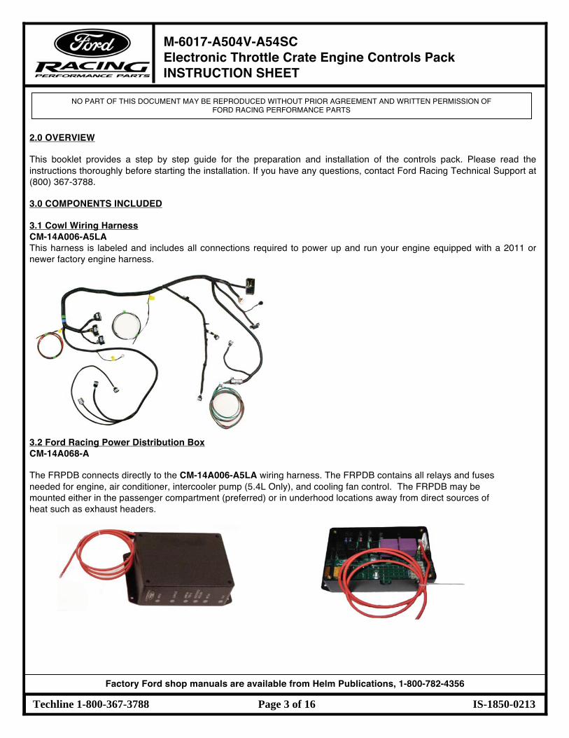
This booklet provides a step by step guide for the preparation and installation of the controls pack. Please read the instructions thoroughly before starting the installation. If you have any questions, contact Ford Racing Technical Support at (800) 367-3788. 3.0 COMPONENTS INCLUDED 3.1 Cowl Wiring Harness CM-14A006-A5LA This harness is labeled and includes all connections required to power up and run your engine equipped with a 2011 or newer factory engine harness.
3.2 Ford Racing Power Distribution Box CM-14A068-A The FRPDB connects directly to the CM-14A006-A5LA wiring harness. The FRPDB contains all relays and fuses needed for engine, air conditioner, intercooler pump (5.4L Only), and cooling fan control. The FRPDB may be mounted either in the passenger compartment (preferred) or in underhood locations away from direct sources of heat such as exhaust headers.
1 M-6017-A504V-A54SC Electronic Throttle Crate Engine Controls Pack INSTRUCTION SHEET
NO PART OF THIS DOCUMENT MAY BE REPRODUCED WITHOUT PRIOR AGREEMENT AND WRITTEN PERMISSION OF FORD RACING PERFORMANCE PARTS
Techline 1-800-367-3788 Page 4 of 16 IS-1850-0213
Factory Ford shop manuals are available from Helm Publications, 1-800-782-4356
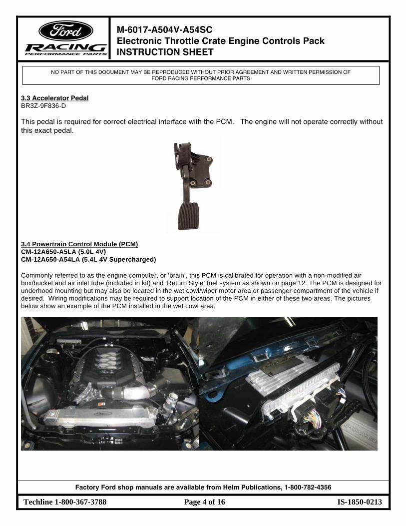
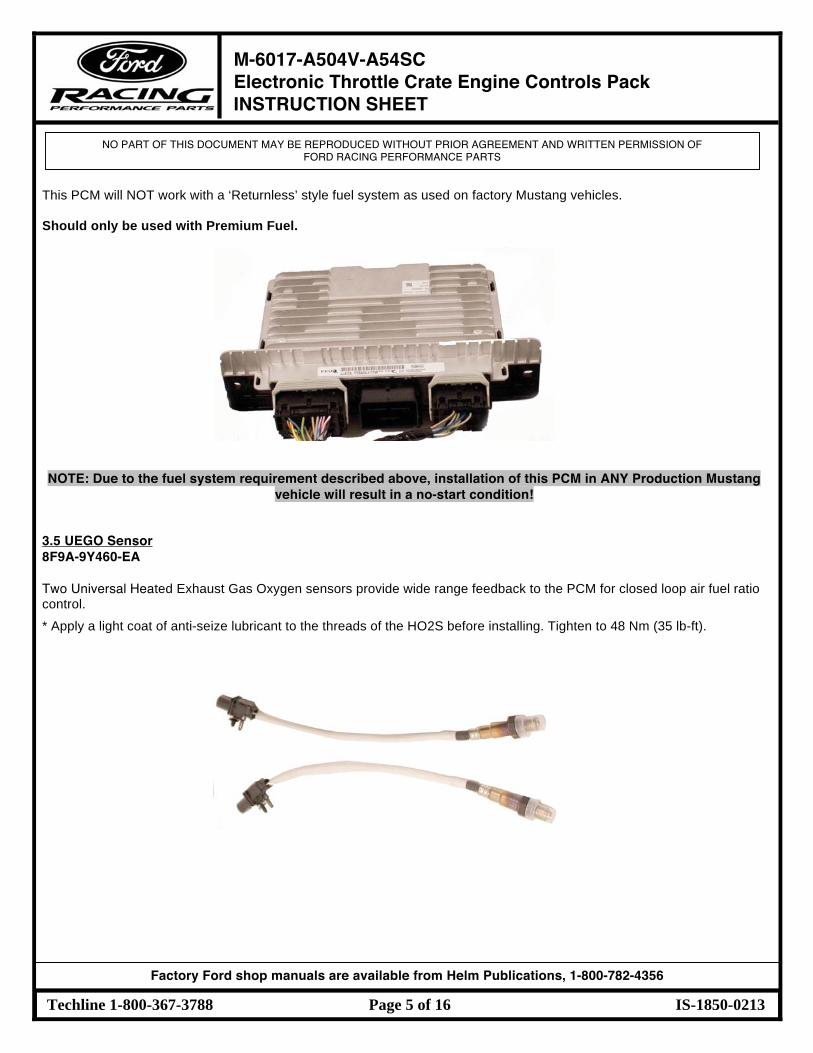
3.3 Accelerator Pedal BR3Z-9F836-D This pedal is required for correct electrical interface with the PCM. The engine will not operate correctly without this exact pedal. 3.4 Powertrain Control Module (PCM) CM-12A650-A5LA (5.0L 4V) CM-12A650-A54LA (5.4L 4V Supercharged) Commonly referred to as the engine computer, or ‘brain’, this PCM is calibrated for operation with a non-modified air box/bucket and air inlet tube (included in kit) and ‘Return Style’ fuel system as shown on page 12. The PCM is designed for underhood mounting but may also be located in the wet cowl/wiper motor area or passenger compartment of the vehicle if desired. Wiring modifications may be required to support location of the PCM in either of these two areas. The pictures below show an example of the PCM installed in the wet cowl area.
1 M-6017-A504V-A54SC Electronic Throttle Crate Engine Controls Pack INSTRUCTION SHEET
NO PART OF THIS DOCUMENT MAY BE REPRODUCED WITHOUT PRIOR AGREEMENT AND WRITTEN PERMISSION OF FORD RACING PERFORMANCE PARTS
Techline 1-800-367-3788 Page 5 of 16 IS-1850-0213
Factory Ford shop manuals are available from Helm Publications, 1-800-782-4356
This PCM will NOT work with a ‘Returnless’ style fuel system as used on factory Mustang vehicles. Should only be used with Premium Fuel.
NOTE: Due to the fuel system requirement described above, installation of this PCM in ANY Production Mustang
vehicle will result in a no-start condition!
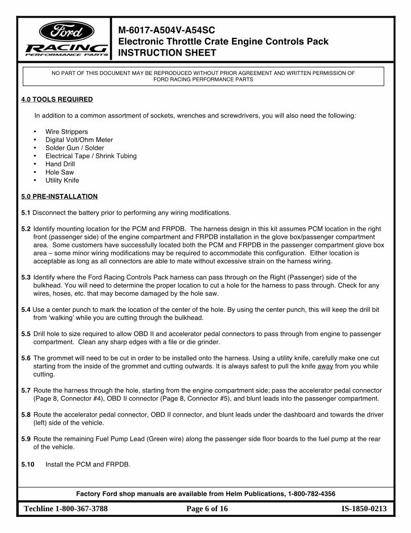
3.5 UEGO Sensor 8F9A-9Y460-EA Two Universal Heated Exhaust Gas Oxygen sensors provide wide range feedback to the PCM for closed loop air fuel ratio control. * Apply a light coat of anti-seize lubricant to the threads of the HO2S before installing. Tighten to 48 Nm (35 lb-ft).
1 M-6017-A504V-A54SC Electronic Throttle Crate Engine Controls Pack INSTRUCTION SHEET
NO PART OF THIS DOCUMENT MAY BE REPRODUCED WITHOUT PRIOR AGREEMENT AND WRITTEN PERMISSION OF FORD RACING PERFORMANCE PARTS
Techline 1-800-367-3788 Page 6 of 16 IS-1850-0213
Factory Ford shop manuals are available from Helm Publications, 1-800-782-4356
4.0 TOOLS REQUIRED In addition to a common assortment of sockets, wrenches and screwdrivers, you will also need the following:
• Wire Strippers • Digital Volt/Ohm Meter • Solder Gun / Solder • Electrical Tape / Shrink Tubing • Hand Drill • Hole Saw • Utility Knife
5.0 PRE-INSTALLATION 5.1 Disconnect the battery prior to performing any wiring modifications. 5.2 Identify mounting location for the PCM and FRPDB. The harness design in this kit assumes PCM location in the right
front (passenger side) of the engine compartment and FRPDB installation in the glove box/passenger compartment area. Some customers have successfully located both the PCM and FRPDB in the passenger compartment glove box area – some minor wiring modifications may be required to accommodate this configuration. Either location is acceptable as long as all connectors are able to mate without excessive strain on the harness wiring.
5.3 Identify where the Ford Racing Controls Pack harness can pass through on the Right (Passenger) side of the
bulkhead. You will need to determine the proper location to cut a hole for the harness to pass through. Check for any wires, hoses, etc. that may become damaged by the hole saw.
5.4 Use a center punch to mark the location of the center of the hole. By using the center punch, this will keep the drill bit
from ʻwalkingʼ while you are cutting through the bulkhead. 5.5 Drill hole to size required to allow OBD II and accelerator pedal connectors to pass through from engine to passenger
compartment. Clean any sharp edges with a file or die grinder. 5.6 The grommet will need to be cut in order to be installed onto the harness. Using a utility knife, carefully make one cut
starting from the inside of the grommet and cutting outwards. It is always safest to pull the knife away from you while cutting.
5.7 Route the harness through the hole, starting from the engine compartment side; pass the accelerator pedal connector
(Page 8, Connector #4), OBD II connector (Page 8, Connector #5), and blunt leads into the passenger compartment. 5.8 Route the accelerator pedal connector, OBD II connector, and blunt leads under the dashboard and towards the driver
(left) side of the vehicle. 5.9 Route the remaining Fuel Pump Lead (Green wire) along the passenger side floor boards to the fuel pump at the rear
of the vehicle. 5.10 Install the PCM and FRPDB.
1 M-6017-A504V-A54SC Electronic Throttle Crate Engine Controls Pack INSTRUCTION SHEET
NO PART OF THIS DOCUMENT MAY BE REPRODUCED WITHOUT PRIOR AGREEMENT AND WRITTEN PERMISSION OF FORD RACING PERFORMANCE PARTS
Techline 1-800-367-3788 Page 7 of 16 IS-1850-0213
Factory Ford shop manuals are available from Helm Publications, 1-800-782-4356
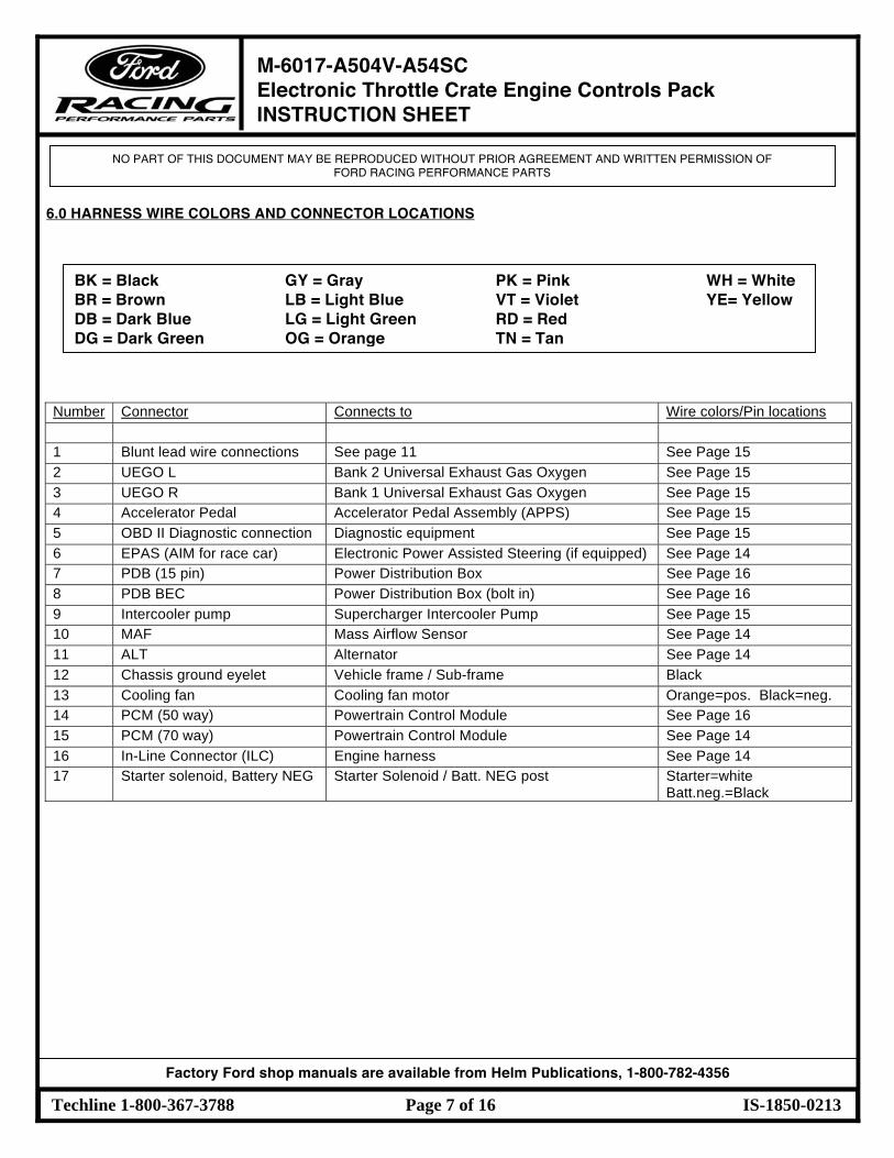
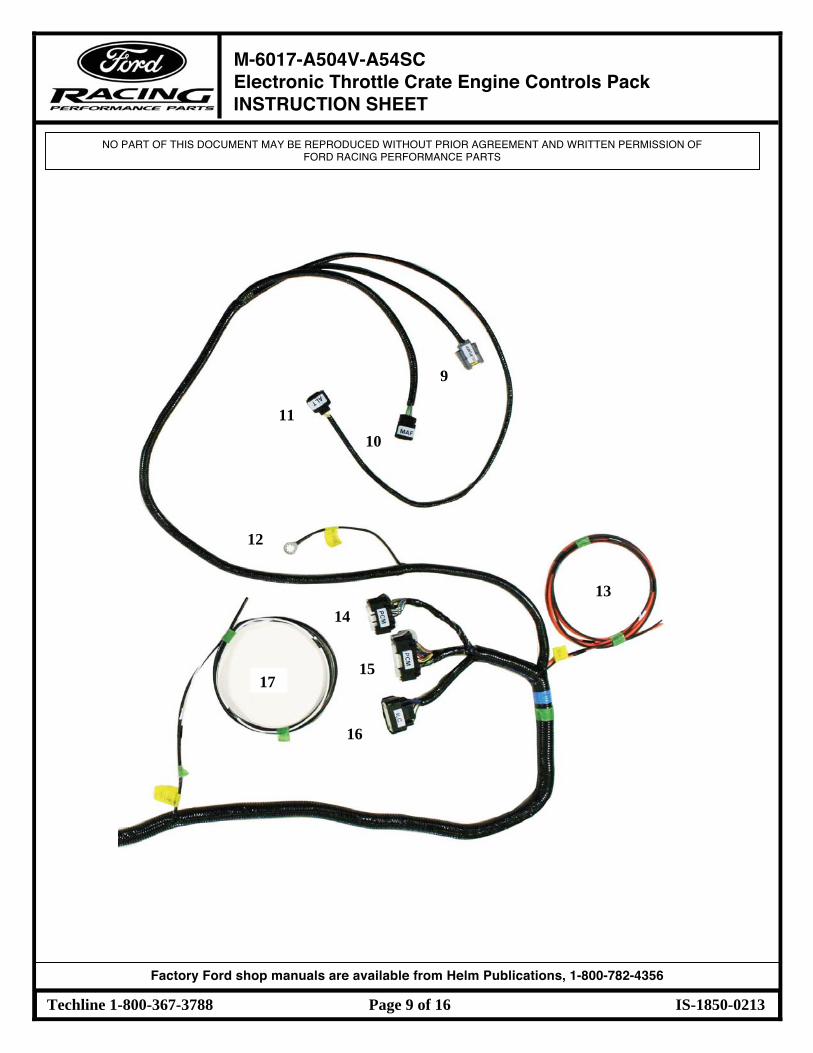
6.0 HARNESS WIRE COLORS AND CONNECTOR LOCATIONS
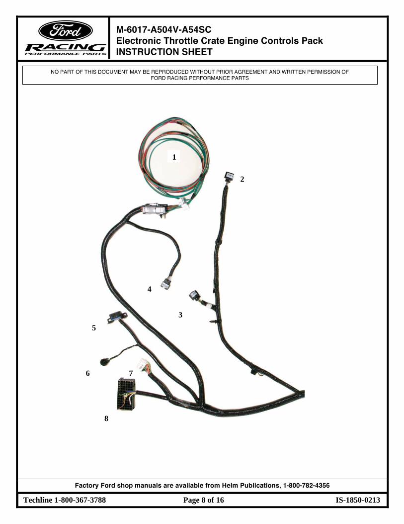
Number Connector Connects to Wire colors/Pin locations 1 Blunt lead wire connections See page 11 See Page 15 2 UEGO L Bank 2 Universal Exhaust Gas Oxygen See Page 15 3 UEGO R Bank 1 Universal Exhaust Gas Oxygen See Page 15 4 Accelerator Pedal Accelerator Pedal Assembly (APPS) See Page 15 5 OBD II Diagnostic connection Diagnostic equipment See Page 15 6 EPAS (AIM for race car) Electronic Power Assisted Steering (if equipped) See Page 14 7 PDB (15 pin) Power Distribution Box See Page 16 8 PDB BEC Power Distribution Box (bolt in) See Page 16 9 Intercooler pump Supercharger Intercooler Pump See Page 15 10 MAF Mass Airflow Sensor See Page 14 11 ALT Alternator See Page 14 12 Chassis ground eyelet Vehicle frame / Sub-frame Black 13 Cooling fan Cooling fan motor Orange=pos. Black=neg. 14 PCM (50 way) Powertrain Control Module See Page 16 15 PCM (70 way) Powertrain Control Module See Page 14 16 In-Line Connector (ILC) Engine harness See Page 14 17 Starter solenoid, Battery NEG Starter Solenoid / Batt. NEG post Starter=white
Batt.neg.=Black
BK = Black GY = Gray PK = Pink WH = White BR = Brown LB = Light Blue VT = Violet YE= Yellow DB = Dark Blue LG = Light Green RD = Red DG = Dark Green OG = Orange TN = Tan
1 M-6017-A504V-A54SC Electronic Throttle Crate Engine Controls Pack INSTRUCTION SHEET
NO PART OF THIS DOCUMENT MAY BE REPRODUCED WITHOUT PRIOR AGREEMENT AND WRITTEN PERMISSION OF FORD RACING PERFORMANCE PARTS
Techline 1-800-367-3788 Page 8 of 16 IS-1850-0213
Factory Ford shop manuals are available from Helm Publications, 1-800-782-4356
2
3
4
1
5
6
8
7
1 M-6017-A504V-A54SC Electronic Throttle Crate Engine Controls Pack INSTRUCTION SHEET
NO PART OF THIS DOCUMENT MAY BE REPRODUCED WITHOUT PRIOR AGREEMENT AND WRITTEN PERMISSION OF FORD RACING PERFORMANCE PARTS
Techline 1-800-367-3788 Page 9 of 16 IS-1850-0213
Factory Ford shop manuals are available from Helm Publications, 1-800-782-4356
11
13
10
9
12
14
15
16
17
1 M-6017-A504V-A54SC Electronic Throttle Crate Engine Controls Pack INSTRUCTION SHEET
NO PART OF THIS DOCUMENT MAY BE REPRODUCED WITHOUT PRIOR AGREEMENT AND WRITTEN PERMISSION OF FORD RACING PERFORMANCE PARTS
Techline 1-800-367-3788 Page 10 of 16 IS-1850-0213
Factory Ford shop manuals are available from Helm Publications, 1-800-782-4356
7.0 HARNESS INSTALLATION
7.1 Attach main engine harness connector (Page 8, Connector #8) to the PDB. Use a Phillips screwdriver to gently snug the mounting screw for this connector. Access to this screw is through a hole in the back side of PDB.
7.2 Attach the PCM Connector (Page 9, Connector #15) to the cowl pocket (outside 70 pin connector) of the PCM 7.3 Attach the Auxiliary Inline Connector (Page 9, Connector #16) to the mating Inline Connector of a 2011 MY or
newer engine harness. 7.4 Attach the 15 pin FRPDB Connector (Page 8, Connector #7) to the FRPDB. Leave the lid off of the FRPDB until
verification of installation is complete to allow for trouble-shooting if necessary. 7.5 Using a sheet metal screw, attach the eyelet (Page 9, Connector #12) to the inner fender or bulkhead. Verify
that you have a good reliable ground path from the battery negative post to the location being used for this eyelet on the chassis. In general, the resistance from the battery ground to this chassis location should be less than 0.1 ohm.
7.6 (5.4L Only) Route the supercharger Intercooler Pump Connector (Page 9, Connector #9) down toward the
bottom of the radiator, and find a suitable location to mount the intercooler pump that will still reach this connector. After mounting the intercooler pump, attach the connector.
7.7 Find a mounting location for the Accelerator Pedal. Ensure that the mounting location is sufficiently strong so
the mounting surface will not fatigue over time from the constant usage of the accelerator pedal. If necessary, fabricate an additional support plate for mounting the accelerator pedal. Once the pedal is mounted, attach the Accelerator Pedal Connector (Page 8, Connector #4)
7.8 Attach the OBD II Diagnostic Connector (Page 8, Connector #5) at a location of your choosing, usually under the
dashboard on the driver (left) side of the vehicle. Verify that the connector, once mounted, does not interfere with any part of your body while in the seated position.
Important Note on the Starting System This kit includes connections and installation instructions for PCM controlled engine starting; however, it is not required that the customer utilize this option. Customers may choose to use their existing non-PCM controlled starting system if desired. If non-PCM controlled starting is used, step 8.2 C may be omitted, and unused blunt leads should be cut to ~2” length and sealed using heat shrink.
1 M-6017-A504V-A54SC Electronic Throttle Crate Engine Controls Pack INSTRUCTION SHEET
NO PART OF THIS DOCUMENT MAY BE REPRODUCED WITHOUT PRIOR AGREEMENT AND WRITTEN PERMISSION OF FORD RACING PERFORMANCE PARTS
Techline 1-800-367-3788 Page 11 of 16 IS-1850-0213
Factory Ford shop manuals are available from Helm Publications, 1-800-782-4356
8.0 WIRING CONNECTIONS
8.1 Locate each of the Blunt Leads. This is where you will need to make all of the soldered connections for the harness.
8.2 Connect the blunt leads as follows:
A. Blunt Lead 1 – Ignition Switch Position (Red/Light Green Wire): Connect this wire to a SINGLE
SOURCE on the ignition switch that provides 12 Volts when the key is in either the ʻStartʼ (cranking) or ʻRunʼ position. It is imperative that this circuit be reliable, the PCM will interpret an intermittent voltage on this signal as a request to shut down the engine! (Hint, if your engine shuts down after a hard launch check here first).
B. Blunt Lead 2 – Fuel Pump (Dark Green): Connect to Fuel Pump positive. Separate ground for fuel pump
must be provided. The fuel pump will be running any time key is on.
C. Blunt Lead 3 – Starter Motor Request (Red/Light Blue): Connect to start node of ignition switch so that 12 volts is provided when engine starting is requested.*
D. Blunt Lead 4 – Clutch Position (Neutral Switch) (Dark Blue/Orange): This circuit must be grounded
either directly to ground or through an optional customer provided clutch pedal switch.* (PCM will not engage the starter without proper ground/switch)
E. Blunt Lead 5 - CTO (Tan/Yellow): This wire is the tachometer lead. This is not a mandatory connection.*
*If non-PCM controlled starting is used, step 8.2 C may be omitted, and unused blunt leads should be cut to ~2” length and sealed using heat shrink.
1 M-6017-A504V-A54SC Electronic Throttle Crate Engine Controls Pack INSTRUCTION SHEET
NO PART OF THIS DOCUMENT MAY BE REPRODUCED WITHOUT PRIOR AGREEMENT AND WRITTEN PERMISSION OF FORD RACING PERFORMANCE PARTS
Techline 1-800-367-3788 Page 12 of 16 IS-1850-0213
Factory Ford shop manuals are available from Helm Publications, 1-800-782-4356
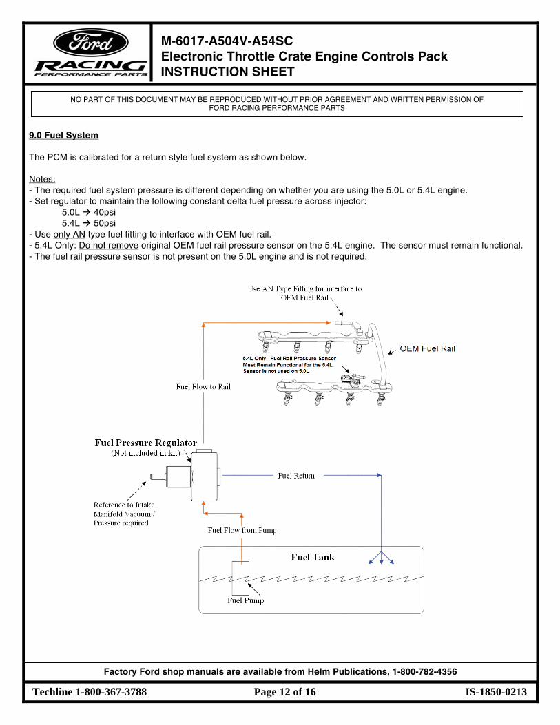
9.0 Fuel System The PCM is calibrated for a return style fuel system as shown below. Notes: - The required fuel system pressure is different depending on whether you are using the 5.0L or 5.4L engine. - Set regulator to maintain the following constant delta fuel pressure across injector:
5.0L 40psi 5.4L 50psi
- Use only AN type fuel fitting to interface with OEM fuel rail. - 5.4L Only: Do not remove original OEM fuel rail pressure sensor on the 5.4L engine. The sensor must remain functional. - The fuel rail pressure sensor is not present on the 5.0L engine and is not required.
1 M-6017-A504V-A54SC Electronic Throttle Crate Engine Controls Pack INSTRUCTION SHEET
NO PART OF THIS DOCUMENT MAY BE REPRODUCED WITHOUT PRIOR AGREEMENT AND WRITTEN PERMISSION OF FORD RACING PERFORMANCE PARTS
Techline 1-800-367-3788 Page 13 of 16 IS-1850-0213
Factory Ford shop manuals are available from Helm Publications, 1-800-782-4356
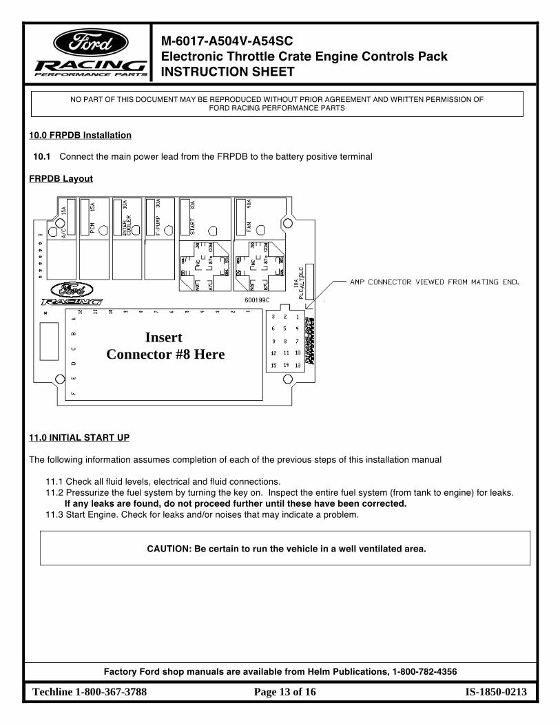
10.0 FRPDB Installation 10.1 Connect the main power lead from the FRPDB to the battery positive terminal
FRPDB Layout
11.0 INITIAL START UP
The following information assumes completion of each of the previous steps of this installation manual
11.1 Check all fluid levels, electrical and fluid connections. 11.2 Pressurize the fuel system by turning the key on. Inspect the entire fuel system (from tank to engine) for leaks.
If any leaks are found, do not proceed further until these have been corrected. 11.3 Start Engine. Check for leaks and/or noises that may indicate a problem.
CAUTION: Be certain to run the vehicle in a well ventilated area.
Insert Connector #8 Here
1 M-6017-A504V-A54SC Electronic Throttle Crate Engine Controls Pack INSTRUCTION SHEET
NO PART OF THIS DOCUMENT MAY BE REPRODUCED WITHOUT PRIOR AGREEMENT AND WRITTEN PERMISSION OF FORD RACING PERFORMANCE PARTS
Techline 1-800-367-3788 Page 14 of 16 IS-1850-0213
Factory Ford shop manuals are available from Helm Publications, 1-800-782-4356
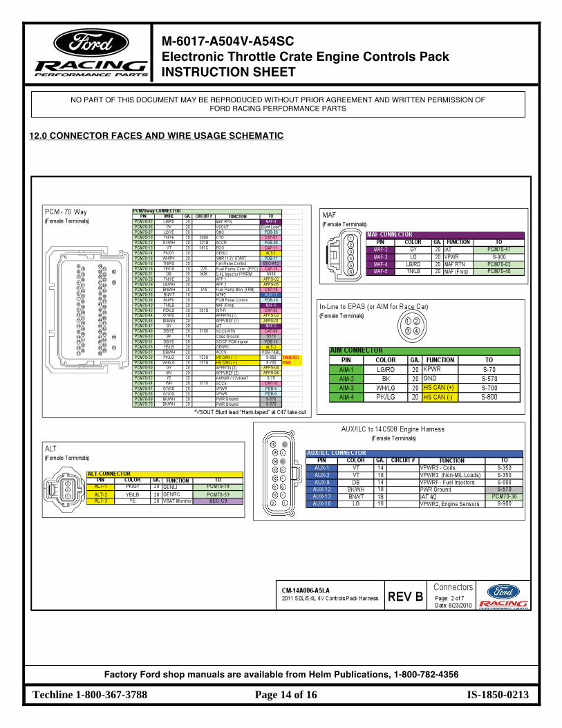
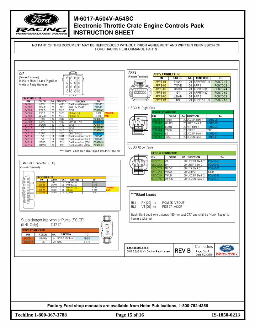
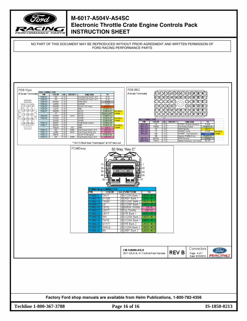
12.0 CONNECTOR FACES AND WIRE USAGE SCHEMATIC
1 M-6017-A504V-A54SC Electronic Throttle Crate Engine Controls Pack INSTRUCTION SHEET
NO PART OF THIS DOCUMENT MAY BE REPRODUCED WITHOUT PRIOR AGREEMENT AND WRITTEN PERMISSION OF FORD RACING PERFORMANCE PARTS
Techline 1-800-367-3788 Page 15 of 16 IS-1850-0213
Factory Ford shop manuals are available from Helm Publications, 1-800-782-4356
1 M-6017-A504V-A54SC Electronic Throttle Crate Engine Controls Pack INSTRUCTION SHEET
NO PART OF THIS DOCUMENT MAY BE REPRODUCED WITHOUT PRIOR AGREEMENT AND WRITTEN PERMISSION OF FORD RACING PERFORMANCE PARTS
Techline 1-800-367-3788 Page 16 of 16 IS-1850-0213
Factory Ford shop manuals are available from Helm Publications, 1-800-782-4356