1 leds and connectors 2 simatic net 3 - siemens · 1 leds and connectors 2 installation, connecting...
TRANSCRIPT
� CP 1243- �1 DNP3
___________________
___________________
___________________
___________________
___________________
___________________
___________________
___________________
___________________
___________________
SIMATIC NET
S7-1200 - Telecontrol CP 1243-1 DNP3
Operating Instructions
07/2013 C79000-G8976-C312-01
Preface
Application and properties 1
LEDs and connectors 2
Installation, connecting up, commissioning
3
Configuration and operation 4
Diagnostics, servicing, maintenance
5
Technical specifications 6
Approvals A
Dimension drawings B
Documentation references C

Siemens AG Industry Sector Postfach 48 48 90026 NÜRNBERG GERMANY
Order number: C79000-G8976-C312 Ⓟ 07/2013 Technical data subject to change
Copyright © Siemens AG 2013. All rights reserved
Legal information Warning notice system
This manual contains notices you have to observe in order to ensure your personal safety, as well as to prevent damage to property. The notices referring to your personal safety are highlighted in the manual by a safety alert symbol, notices referring only to property damage have no safety alert symbol. These notices shown below are graded according to the degree of danger.
DANGER indicates that death or severe personal injury will result if proper precautions are not taken.
WARNING indicates that death or severe personal injury may result if proper precautions are not taken.
CAUTION indicates that minor personal injury can result if proper precautions are not taken.
NOTICE indicates that property damage can result if proper precautions are not taken.
If more than one degree of danger is present, the warning notice representing the highest degree of danger will be used. A notice warning of injury to persons with a safety alert symbol may also include a warning relating to property damage.
Qualified Personnel The product/system described in this documentation may be operated only by personnel qualified for the specific task in accordance with the relevant documentation, in particular its warning notices and safety instructions. Qualified personnel are those who, based on their training and experience, are capable of identifying risks and avoiding potential hazards when working with these products/systems.
Proper use of Siemens products Note the following:
WARNING Siemens products may only be used for the applications described in the catalog and in the relevant technical documentation. If products and components from other manufacturers are used, these must be recommended or approved by Siemens. Proper transport, storage, installation, assembly, commissioning, operation and maintenance are required to ensure that the products operate safely and without any problems. The permissible ambient conditions must be complied with. The information in the relevant documentation must be observed.
Trademarks All names identified by ® are registered trademarks of Siemens AG. The remaining trademarks in this publication may be trademarks whose use by third parties for their own purposes could violate the rights of the owner.
Disclaimer of Liability We have reviewed the contents of this publication to ensure consistency with the hardware and software described. Since variance cannot be precluded entirely, we cannot guarantee full consistency. However, the information in this publication is reviewed regularly and any necessary corrections are included in subsequent editions.

CP 1243-1 DNP3 Operating Instructions, 07/2013, C79000-G8976-C312-01 3
Preface
Validity of this manual This document contains information on the following product:
CP 1243-1 DNP3 Order number 6GK7 243-1JX30-0XE0 Hardware product version 1 Firmware version V1.0
The CP 1243-1 DNP3 is a communications processor of the SIMATIC S7-1200 for system connection to Industrial Ethernet. It supports the DNP3 protocol for telecontrol applications.
Figure 1 CP 1243-1 DNP3
At the top right behind the hinged cover of the module housing, you will see the hardware product version printed as a placeholder "X" after the order number. If the printed text is, for example, "X 2 3 4", "X" would be the placeholder for hardware product version 1.

Preface
CP 1243-1 DNP3 4 Operating Instructions, 07/2013, C79000-G8976-C312-01
Product name In this document, you will find the following designations used for the product being described here:
● CP 1243-1 DNP3
Designation of the CP 1243-1 DNP3 with support of the DNP3 protocol (6GK7 243-1IX30-0XE0)
● CP
Simplified designation of the product "CP 1243-1 DNP3"
Purpose of the manual This manual describes the properties of this module and supports you when installing and commissioning the device.
The necessary configuration steps are described in the form of an overview.
You will also find information about the diagnostics options of the device.
New in this issue First issue
Replaced documentation None
Current manual release on the Internet You will also find the current version of this manual on the Internet pages of Siemens Automation Customer Support under the following entry ID:
69270828 (http://support.automation.siemens.com/WW/view/en/69270828)
Required experience To install, commission and operate the CP, you require experience in the following areas:
● Automation engineering
● Setting up the SIMATIC S7-1200
● SIMATIC STEP 7 Basic V12 / Professional V12
● DNP3 protocol
Requirements for use of the module You will find the requirements for using the module in the section Requirements for configuration and operation (Page 27).
Preface
CP 1243-1 DNP3 Operating Instructions, 07/2013, C79000-G8976-C312-01 5
Sources of information and other documentation You will find an overview of further reading and references in the Appendix of this manual.
Security information Siemens provides automation and drive products with industrial security functions that support the secure operation of plants or machines. They are an important component in a holistic industrial security concept. With this in mind, our products undergo continuous development. We therefore recommend that you keep yourself informed with respect to our product updates. Please find further information and newsletters on this subject at: http://support.automation.siemens.com.
To ensure the secure operation of a plant or machine it is also necessary to take suitable preventive action (e.g. cell protection concept) and to integrate the automation and drive components into a state-of-the-art holistic industrial security concept for the entire plant or machine. Any third-party products that may be in use must also be taken into account. Please find further information at: http://www.siemens.com/industrialsecurity
SIMATIC NET glossary Explanations of the specialist terms used in this documentation can be found in the SIMATIC NET glossary.
You will find the SIMATIC NET glossary here:
● SIMATIC NET Manual Collection
The DVD ships with certain SIMATIC NET products.
● On the Internet under the following entry ID:
50305045 (http://support.automation.siemens.com/WW/view/en/50305045)
Training, Service & Support You will find information on Training, Service & Support in the multi--language document "DC_support_99.pdf" on the data medium supplied with the documentation.
License conditions
Note Open source software
Read the license conditions for open source software carefully before using the product. The acceptance of the disclaimers of liability and warranty it contains is a clear precondition of the use of open source software.
You will find license conditions in the following documents on the supplied data medium:
● DOC_OSS-Siemens_74.pdf
● DOC_OSS-CP1243-1DNP3_76.pdf

Preface
CP 1243-1 DNP3 6 Operating Instructions, 07/2013, C79000-G8976-C312-01
CP 1243-1 DNP3 Operating Instructions, 07/2013, C79000-G8976-C312-01 7
Table of contents
Preface ...................................................................................................................................................... 3
1 Application and properties ......................................................................................................................... 9
1.1 Configuration example ...................................................................................................................9
1.2 Communications services ............................................................................................................11
1.3 Other services and properties......................................................................................................12
1.4 Configuration limits and performance data ..................................................................................13
1.5 DNP3 device profile .....................................................................................................................14
2 LEDs and connectors .............................................................................................................................. 15
2.1 Opening the covers of the housing ..............................................................................................15
2.2 LEDs ............................................................................................................................................16
2.3 Electrical connections ..................................................................................................................19 2.3.1 Power supply................................................................................................................................19 2.3.2 Ethernet interface X1P1...............................................................................................................19
3 Installation, connecting up, commissioning.............................................................................................. 21
3.1 Important notes on using the device............................................................................................21 3.1.1 Notices on use in hazardous areas .............................................................................................21 3.1.2 Notices regarding use in hazardous areas according to ATEX...................................................22 3.1.3 Notices regarding use in hazardous areas according to UL HazLoc...........................................23
3.2 Installation....................................................................................................................................23
3.3 Installing, connecting up and commissioning ..............................................................................26
4 Configuration and operation..................................................................................................................... 27
4.1 Requirements for configuration and operation.............................................................................27
4.2 Configuration................................................................................................................................27 4.2.1 Configuration in STEP 7 ..............................................................................................................27 4.2.2 Information required for configuration..........................................................................................29 4.2.3 Configuring datapoints and messages (e-mails) .........................................................................30 4.2.4 DNP3 implementation level..........................................................................................................31 4.2.5 Datapoint types ............................................................................................................................31 4.2.6 Information on configuring individual parameters ........................................................................33 4.2.7 CPU scan cycle............................................................................................................................35 4.2.8 Types of transmission and event classes ....................................................................................36 4.2.9 Analog value preprocessing.........................................................................................................36
5 Diagnostics, servicing, maintenance........................................................................................................ 39
5.1 Diagnostics options......................................................................................................................39
5.2 Downloading firmware .................................................................................................................40
5.3 Module replacement ....................................................................................................................40

Table of contents
CP 1243-1 DNP3 8 Operating Instructions, 07/2013, C79000-G8976-C312-01
6 Technical specifications........................................................................................................................... 41
A Approvals................................................................................................................................................. 43
B Dimension drawings ................................................................................................................................ 47
C Documentation references....................................................................................................................... 49
Index........................................................................................................................................................ 51
CP 1243-1 DNP3 Operating Instructions, 07/2013, C79000-G8976-C312-01 9
Application and properties 11.1 Configuration example
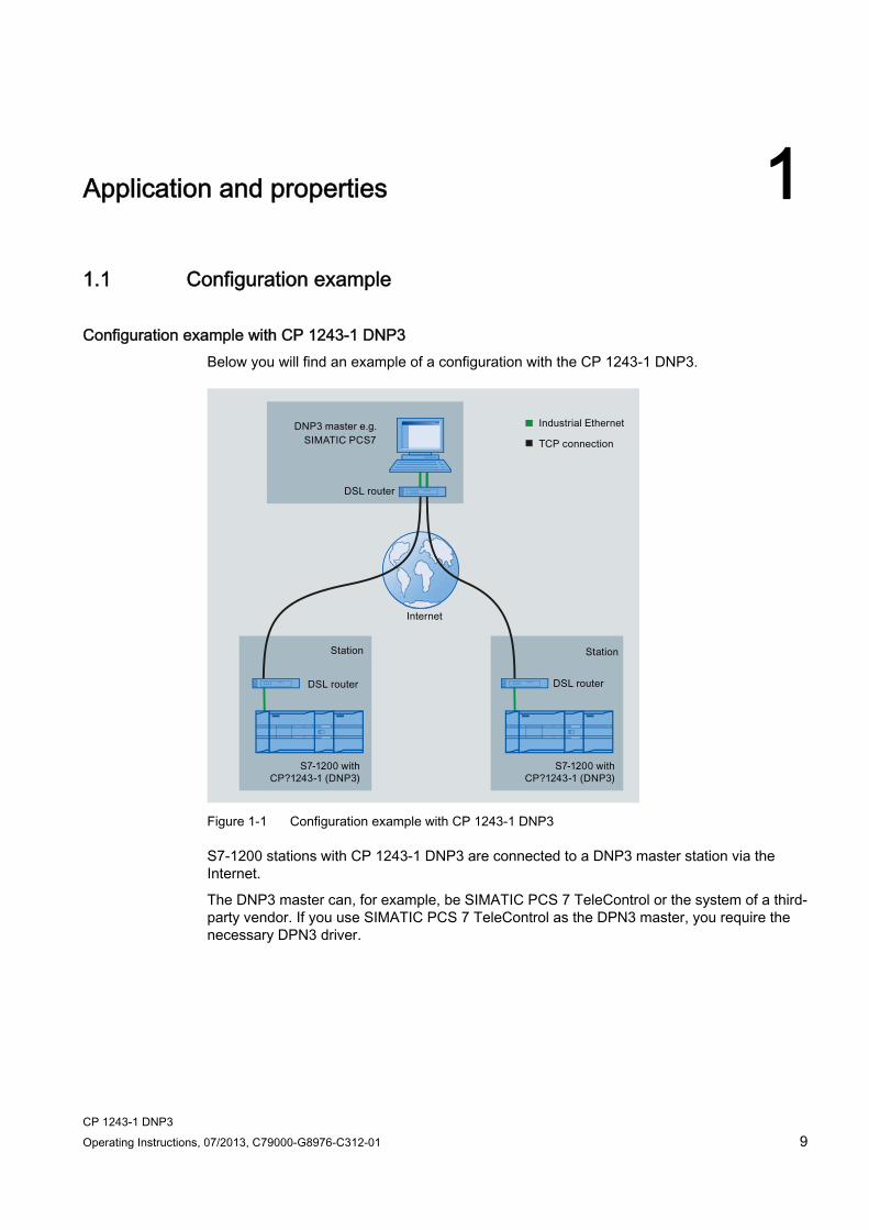
Configuration example with CP 1243-1 DNP3 Below you will find an example of a configuration with the CP 1243-1 DNP3.
Figure 1-1 Configuration example with CP 1243-1 DNP3
S7-1200 stations with CP 1243-1 DNP3 are connected to a DNP3 master station via the Internet.
The DNP3 master can, for example, be SIMATIC PCS 7 TeleControl or the system of a third-party vendor. If you use SIMATIC PCS 7 TeleControl as the DPN3 master, you require the necessary DPN3 driver.

Application and properties 1.1 Configuration example
CP 1243-1 DNP3 10 Operating Instructions, 07/2013, C79000-G8976-C312-01
Configuration example with CP 1243-1 DNP3 and redundant control center The following example shows a configuration with the CP 1243-1 DNP3 and a redundant control center (DNP3 master). The two devices of the redundant DNP3 master are addressed by the CP via one DNP3 address but two different IP addresses.
Figure 1-2 Configuration example with CP 1243-1 DNP3 and redundant control center

Application and properties 1.2 Communications services
CP 1243-1 DNP3 Operating Instructions, 07/2013, C79000-G8976-C312-01 11
1.2 Communications services
Communications services The CP supports the following communications services:
● DNP3 protocol
Communication is based on the DNP3 SPECIFICATION Version 2.x (2007/2009).
The CP is a communications processor of the SIMATIC S7-1200 for system connection to Industrial Ethernet using the DNP3 protocol for telecontrol applications.
An S7-1200 with CP 1243-1 DNP3 operates as a DNP3 station (Outstation).
The CP supports the implementation level 1 - 4 (DNP3 Application Layer protocol Level). You will find a description of the other functions in the section DNP3 implementation level (Page 31).
● S7 communication and PG/OP communication with the following functions:
– PUT/GET as client and server for data exchange with remote stations (S7-300/400/1200/1500)
– PG functions
– Operator control and monitoring functions (HMI)
Application and properties 1.3 Other services and properties
CP 1243-1 DNP3 12 Operating Instructions, 07/2013, C79000-G8976-C312-01
1.3 Other services and properties
Other services ● Security functions
The CP can use the security functions specified in the DNP3 protocol and therefore secure communication in the DNP3 network, including the following:
– Secure authentication (SA) of the communications partner
The CP checks whether the communications partner has the right to access the CP.
Formation of the Message Authentication Code (MAC) using symmetrical (pre-shared key, PSK) or asymmetrical cryptography (public/private keys)
Use of IPsec for transferring the key
– Logging of security events:
- Successful and failed authentication
- Key exchange
- Statistical counter
You can enable the security function in the configuration with the required options.
● IP configuration - IPv4 and IPv6
The essential features of IP configuration for the CP:
– The CP supports IP addresses according to IPv4 and IPv6.
– An IPv6 address can be used in addition to an IPv4 address.
– Address assignment:
The IP address, the subnet mask and the address of a gateway can be set manually in the configuration.
As an alternative, the IP address can be obtained from a DHCP server or by other means outside the configuration.
● Time-of-day synchronization over Industrial Ethernet
The CP can the have its local time-of-day synchronized by the partner (DNP3 master) as UTC time. The time stamp is transferred in the 48-bit format. The time is forwarded by the CP to the CPU.
The time-of-day synchronization is set in the SIMATIC STEP 7 configuration.
● Redundancy
The CP can communicate with a redundant control system (DNP3 master).
● Storing DNP3 events
The CP can store DNP3 events of different classes and transfer them together to the master.
Application and properties 1.4 Configuration limits and performance data
CP 1243-1 DNP3 Operating Instructions, 07/2013, C79000-G8976-C312-01 13
● Data transfer is on request or triggered
The sending of data to the master can be triggered in two ways:
– At the request of the master
– Triggered by various selectable criteria
● Messages / e-mail
With configured events in the process image of the CPU, the CP can send messages as e-mails. The data of the events to be sent by e-mail are configured using PLC tags.
● Analog value processing
Analog values can be preprocessed on the CP according to various methods.
● TeleService
A TeleService connection can be established between an engineering station with STEP 7 installed on it and the remote S7-1200.
You can use the TeleService connection for the following purposes:
– Downloading project or program data from the STEP 7 project to the station
– Querying diagnostics data on the station
1.4 Configuration limits and performance data
Number of CMs/CPs per station In each S7-1200 station, up to three CMs/CPs can be plugged in and configured; this allows three CP 1243-1 modules.
Connection resources ● TCP connections to DNP3 masters
The CP can establish connections to up to 4 DPN3 masters. These can be single or redundant DNP3 masters.
In the case of 4 redundant DNP3 masters, this would be 8 physical devices addressed using different IP addresses.
● TeleService
1 connection resource is reserved for TeleService.
● S7 connections
8 connection resources for S7 connections (PUT/GET)
● PG/OP connections
– 1 connection resource for PG connections
– 3 connection resources for OP connections
Application and properties 1.5 DNP3 device profile
CP 1243-1 DNP3 14 Operating Instructions, 07/2013, C79000-G8976-C312-01
Number of PLC tags for datapoint configuration The maximum number of PLC tags that can be used for datapoint configuration is 200.
User data The data to be transferred by the CP is assigned to datapoints in the STEP 7 configuration. The size of the user data per datapoint depends on the data type of the relevant datapoint.
Contiguous memory areas can be transferred up to size of 64 bytes using datapoint types of the object groups 110 (Octet String) and 111 (Octet String Event). You will find details in the information system of STEP 7 and in the section Datapoint types (Page 31).
Messages / e-mail Up to 10 messages can be configured in STEP 7 and sent as e-mails.
1.5 DNP3 device profile
Detailed information on DNP3 attributes in the DNP3 device profile You will find a detailed overview of the attributes and properties specified in the DNP3 protocol and supported by the CP in the DNP3 device profile.
You will find the DNP3 device profile of the CP 1243-1 DNP3 on the Internet pages of Siemens Automation Customer Support under the following entry ID:
68853485 (http://support.automation.siemens.com/WW/view/en/69270828)

CP 1243-1 DNP3 Operating Instructions, 07/2013, C79000-G8976-C312-01 15
LEDs and connectors 22.1 Opening the covers of the housing
Location of the display elements and the electrical connectors The LEDs for the detailed display of the module statuses are located behind the upper cover of the module housing.
The Ethernet connector is located behind the lower hinged cover of the module.
Opening the covers of the housing Open the upper or lower cover of the housing by pulling it down or up as shown by the arrows in the illustration. The covers extend beyond the housing to give you a grip.
Figure 2-1 Opening the covers of the housing

LEDs and connectors 2.2 LEDs
CP 1243-1 DNP3 16 Operating Instructions, 07/2013, C79000-G8976-C312-01
2.2 LEDs
LEDs of the module The module has various LEDs for displaying the status:
● LED on the front panel
The "DIAG" LED that is always visible shows the basic statuses of the module.
● LEDs below the upper cover of the housing
The LEDs below the upper cover provide more detailed information on the module status.
Table 2- 1 LED on the front panel
LED / colors Name Meaning
(red / green)
DIAG Basic status of the module
Table 2- 2 LEDs below the upper cover of the housing
LED (color) Name Meaning
(green)
LINK Status of the connection to Industrial Ethernet
(green)
CONNECT Status of the connections to masters
(green)
VPN - inactive -
(green)
TELESERVICE Status of the TeleService connection
LED colors and illustration of the LED statuses The LED symbols in the following tables have the following significance:
Table 2- 3 Meaning of the LED symbols
Symbol -
LED status OFF ON (steady light) Flashing Not relevant
LEDs and connectors 2.2 LEDs
CP 1243-1 DNP3 Operating Instructions, 07/2013, C79000-G8976-C312-01 17
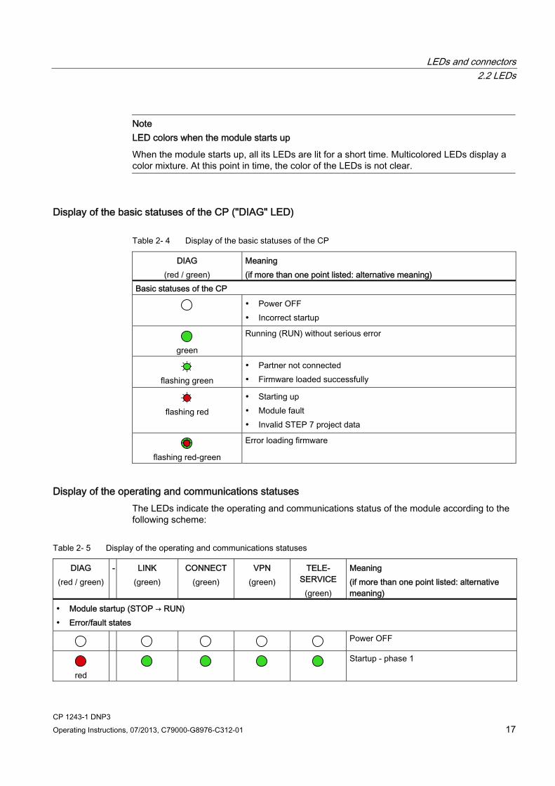
Note LED colors when the module starts up
When the module starts up, all its LEDs are lit for a short time. Multicolored LEDs display a color mixture. At this point in time, the color of the LEDs is not clear.
Display of the basic statuses of the CP ("DIAG" LED)
Table 2- 4 Display of the basic statuses of the CP
DIAG (red / green)
Meaning (if more than one point listed: alternative meaning)
Basic statuses of the CP
Power OFF Incorrect startup
green
Running (RUN) without serious error
flashing green
Partner not connected Firmware loaded successfully
flashing red
Starting up Module fault Invalid STEP 7 project data
flashing red-green
Error loading firmware
Display of the operating and communications statuses The LEDs indicate the operating and communications status of the module according to the following scheme:
Table 2- 5 Display of the operating and communications statuses
DIAG (red / green)
- LINK (green)
CONNECT (green)
VPN (green)
TELE-SERVICE
(green)
Meaning (if more than one point listed: alternative meaning)
Module startup (STOP → RUN) Error/fault states
Power OFF
red
Startup - phase 1

LEDs and connectors 2.2 LEDs
CP 1243-1 DNP3 18 Operating Instructions, 07/2013, C79000-G8976-C312-01
DIAG (red / green)
- LINK (green)
CONNECT (green)
VPN (green)
TELE-SERVICE
(green)
Meaning (if more than one point listed: alternative meaning)
flashing red
- Startup - phase 2
green
- - - - Running (RUN) without serious error
Incorrect startup
red
- - - Invalid STEP 7 project data
flashing red
- - - Missing STEP 7 project data
flashing red
- - Backplane bus error
Connection to Industrial Ethernet - - - - Connection to Industrial Ethernet exists
green
- - - Connection to Industrial Ethernet being established
IP address being obtained.
- - - - No connection to Industrial Ethernet
Connection to communications partners
green
- - Connection established to at least one partner
green
- - Partner reachable, CPU in STOP mode
flashing green
- - Partner not reachable, CPU in RUN mode
flashing green
- - Partner not reachable, CPU in STOP mode
TeleService connection
green
- - TeleService session running 1
green
- - Attempted login to TeleService session
green
- - - No connection to engineering station
Loading firmware

LEDs and connectors 2.3 Electrical connections
CP 1243-1 DNP3 Operating Instructions, 07/2013, C79000-G8976-C312-01 19
DIAG (red / green)
- LINK (green)
CONNECT (green)
VPN (green)
TELE-SERVICE
(green)
Meaning (if more than one point listed: alternative meaning)
Loading firmware. The DIAG LED flashes alternating red and green.
flashing green
Firmware was successfully loaded.
flashing red
Error loading firmware
1 When a TeleServiceconnection is being established, the "TELESERVICE" LED is lit for at least 10 minutes.
2.3 Electrical connections
2.3.1 Power supply
Power supply The CM is supplied with power from the backplane bus. It does not require a separate power supply.
2.3.2 Ethernet interface X1P1
Ethernet interface The Ethernet connector is located behind the lower hinged cover of the module. The interface is an RJ-45 jack according to IEEE 802.3.
The pin assignment and other data relating to the Ethernet interface can be found in the section Technical specifications (Page 41).

LEDs and connectors 2.3 Electrical connections
CP 1243-1 DNP3 20 Operating Instructions, 07/2013, C79000-G8976-C312-01

CP 1243-1 DNP3 Operating Instructions, 07/2013, C79000-G8976-C312-01 21
Installation, connecting up, commissioning 33.1 Important notes on using the device
Safety notices on the use of the device Note the following safety notices when setting up and operating the device and during all associated work such as installation, connecting up or replacing the device.
Overvoltage protection
NOTICE Protection of the external power supply
If power is supplied to the module or station over longer power cables or networks, the coupling in of strong electromagnetic pulses onto the power supply cables is possible. This can be caused, for example by lightning strikes or switching of higher loads.
The connector of the external power supply is not protected from strong electromagnetic pulses. To protect it, an external overvoltage protection module is necessary. The manufacturers of industrial overvoltage protection devices produce suitable modules.
3.1.1 Notices on use in hazardous areas
WARNING EXPLOSION HAZARD
DO NOT OPEN WHEN ENERGIZED.

Installation, connecting up, commissioning 3.1 Important notes on using the device
CP 1243-1 DNP3 22 Operating Instructions, 07/2013, C79000-G8976-C312-01
WARNING The equipment is designed for operation with Safety Extra-Low Voltage (SELV) by a Limited Power Source (LPS).
This means that only SELV / LPS complying with IEC 60950-1 / EN 60950-1 / VDE 0805-1 must be connected to the power supply terminals. The power supply unit for the equipment power supply must comply with NEC Class 2, as described by the National Electrical Code (r) (ANSI / NFPA 70).
If the equipment is connected to a redundant power supply (two separate power supplies), both must meet these requirements.
WARNING EXPLOSION HAZARD
DO NOT CONNECT OR DISCONNECT EQUIPMENT WHEN A FLAMMABLE OR COMBUSTIBLE ATMOSPHERE IS PRESENT.
WARNING EXPLOSION HAZARD
SUBSTITUTION OF COMPONENTS MAY IMPAIR SUITABILITY FOR CLASS I, DIVISION 2 OR ZONE 2.
WARNING When used in hazardous environments corresponding to Class I, Division 2 or Class I, Zone 2, the device must be installed in a cabinet or a suitable enclosure.
3.1.2 Notices regarding use in hazardous areas according to ATEX
WARNING Requirements for the cabinet/enclosure
To comply with EU Directive 94/9 (ATEX95), this enclosure must meet the requirements of at least IP54 in compliance with EN 60529.

Installation, connecting up, commissioning 3.2 Installation
CP 1243-1 DNP3 Operating Instructions, 07/2013, C79000-G8976-C312-01 23
WARNING If the cable or conduit entry point exceeds 70 °C or the branching point of conductors exceeds 80 °C, special precautions must be taken. If the equipment is operated in an air ambient in excess of 50 °C, only use cables with admitted maximum operating temperature of at least 80 °C.
WARNING Take measures to prevent transient voltage surges of more than 40% of the rated voltage. This is the case if you only operate devices with SELV (safety extra-low voltage).
3.1.3 Notices regarding use in hazardous areas according to UL HazLoc
WARNING EXPLOSION HAZARD
DO NOT DISCONNECT WHILE CIRCUIT IS LIVE UNLESS AREA IS KNOWN TO BE NON-HAZARDOUS.
This equipment is suitable for use in Class I, Division 2, Groups A, B, C and D or non-hazardous locations only.
This equipment is suitable for use in Class I, Zone 2, Group IIC or non-hazardous locations only.
3.2 Installation
Prior to installation and commissioning
CAUTION Read the system manual "S7-1200 Programmable Controller"
Prior to installation, connecting up and commissioning, read the relevant sections in the system manual "S7-1200 Programmable Controller", refer to the documentation in the Appendix.
When installing and connecting up, keep to the procedures described in the system manual "S7-1200 Programmable Controller".

Installation, connecting up, commissioning 3.2 Installation
CP 1243-1 DNP3 24 Operating Instructions, 07/2013, C79000-G8976-C312-01
Pulling/plugging the module
NOTICE Turning off the station when plugging/pulling the module
Before pulling or plugging the module, always turn off the power supply to the station.
Dimensions for installation
Figure 3-1 Dimensions for installation of the S7-1200
Table 3- 1 Dimensions for installation (mm)
S7-1200 devices Width A Width B * CPU 1211C, CPU 1212C 90 mm 45 mm CPU (examples) CPU 1214C 110 mm 55 mm CM 1241 RS-232 and CM 1241 RS-485 30 mm 15 mm CM 1243-5 (PROFIBUS master) CM 1242-5 (PROFIBUS slave)
30 mm 15 mm
CP 1242-7 (GPRS CP) 30 mm 15 mm
Communications interfaces (examples)
CP 1243-1 DNP3 30 mm 15 mm
* Width B: The distance between the edge of the housing and the center of the hole in the DIN rail mounting clip
You will find detailed dimensions of the module in the section Dimension drawings (Page 47).

Installation, connecting up, commissioning 3.2 Installation
CP 1243-1 DNP3 Operating Instructions, 07/2013, C79000-G8976-C312-01 25
DIN rail clamps, control panel installation All CPUs, SMs, CMs and CPs can be installed on the 35 mm DIN rail in the cabinet. Use the pull-out DIN rail mounting clips to secure the device to the rail. These mounting clips also lock into place when they are extended to allow the device to be installed in a switching panel. The inner dimension of the hole for the DIN rail mounting clips is 4.3 mm.
Installation location
NOTICE Installation location
The module must be installed so that its upper and lower ventilation slits are not covered, allowing adequate ventilation. Above and below the device, there must be a clearance of 25 mm to allow air to circulate and prevent overheating.
Remember that the permitted temperature ranges depend on the position of the installed device.
Device position / permitted temperature range Installation location Horizontal installation of the rack: -20 ℃ to 60 ℃
Vertical installation of the rack: -20 ℃ to 50 ℃

Installation, connecting up, commissioning 3.3 Installing, connecting up and commissioning
CP 1243-1 DNP3 26 Operating Instructions, 07/2013, C79000-G8976-C312-01
3.3 Installing, connecting up and commissioning
Configuration prior to commissioning One requirement for the commissioning of the module is the completeness of the STEP 7 project data (see below). You should also read the section "Configuration (Page 27)".
Installing, connecting up and commissioning the module
Note Connection with power off
Only wire up the S7-1200 with the power turned off.
Table 3- 2 Procedure for installation and connecting up
Step What to do Notes and explanations 1 Mount the CP on the DIN rail and connect it to
the module to its right. Use a 35 mm DIN rail. The slots to the left of the CPU are permitted.
2 Secure the DIN rail. 3 Connect the Ethernet cable to the CP. You will find the pinout of the interface in the section Technical
specifications (Page 41). 4 Turn on the power supply. 5 Close the front covers of the module and keep
them closed during operation.
6 The remaining steps in commissioning involve downloading the STEP 7 project data.
The STEP 7 project data of the CP is transferred when you load to the station. To load the station, connect the engineering station on which the project data is located to the Ethernet interface of the CPU. You will find more detailed information on loading in the following sections of the STEP 7 information system: "Loading project data" "Using online and diagnostics functions"

CP 1243-1 DNP3 Operating Instructions, 07/2013, C79000-G8976-C312-01 27
Configuration and operation 44.1 Requirements for configuration and operation
Hardware requirements ● In the remote station
– Apart from the CP, on the remote S7-1200 you require a CPU with firmware version V3.0.
– For data transfer via the Internet, you require a suitable router for the Internet connection.
● In the master station
– A compatible DNP3 master
– For data transfer via the Internet, you require a suitable router for the Internet connection.
– If TeleService is to be used, an engineering station with STEP 7 is required.
Configuration software To configure the module, the following configuration tool is required:
STEP 7 Basic V12.0 SP1
Software for TeleService functions STEP 7 in the version specified above
4.2 Configuration
4.2.1 Configuration in STEP 7
Configuration in STEP 7 You configure the modules and networks in SIMATIC STEP 7. You will find the required version in the section Requirements for configuration and operation (Page 27).
You can configure a maximum of three CMs/CPs per station.
Configuration and operation 4.2 Configuration
CP 1243-1 DNP3 28 Operating Instructions, 07/2013, C79000-G8976-C312-01
Communication with a redundant control system If you insert several CPs in an S7-1200, you can establish redundant communications paths. This is only possible if the control system supports redundant transmission paths to the same station.
Even with a single CP 1243-1 DNP3, an S7-1200 can communicate with a redundant DNP3 master. The two devices of the redundant DNP3 master are addressed by the CP via one DNP3 address but two different IP addresses.
How to configure in STEP 7 Follow the steps below when configuring:
1. Create a STEP 7 project.
2. Insert the required SIMATIC stations.
Configuration of the DNP3 master stations and connections is not necessary.
3. Insert the CPs and the required input and output modules in the stations.
4. Create an Ethernet network.
5. Connect the stations to the Ethernet subnet.
6. Configure the inserted CPs.
For details on configuring the communication, refer to the following section.
7. Save the project.
You will find more detailed information on configuring the CP in the Information system of STEP 7 and in the following sections.
Configuring communication (datapoint configuration) CP communication is not programmed using program blocks but configured using datapoints. For more detailed information, refer to the following section:
Requirement for configuring the communication One requirement for configuring CP communication is the programming of the assigned CPU and the input and output data of the station. PLC tags must also be created to assign the user data to the datapoints.
Loading and storing the configuration data When you load the station, the project data of the station including the configuration data of the CP is stored on the CPU.
You will find information on loading the station in the STEP 7 information system.

Configuration and operation 4.2 Configuration
CP 1243-1 DNP3 Operating Instructions, 07/2013, C79000-G8976-C312-01 29
4.2.2 Information required for configuration To configure and commission the CP, the following information is required:
Address information The following information is required for the STEP 7 configuration of the CP:
● Address of the DNP3 master
– IP address
or
– Name that can be resolved with DNS
● Port number of the listener port of the DNP3 master
● DNS server address(es)
You require the DNS server address if you address the DNP3 master using a name that can be resolved by DNS.
E-mail If messages are sent as e-mails, you require the following information for configuration in STEP 7:
● Access data of the SMTP server
– Address
– Port number
– User name
– Password
● Email address of the recipient
Information required for DNP3 security functions For secure connection establishment to the DNP3 master, you require the following:
● Pre-shared key
– The pre-shared key must be produced by the DNP3 master or another system. The pre-shared key is stored in the file system of the engineering station and imported during configuration of the CP in STEP 7.
● Length information about the pre-shared key
The length of the pre-shared key must be known when configuring the CP in STEP 7.
Configuration and operation 4.2 Configuration
CP 1243-1 DNP3 30 Operating Instructions, 07/2013, C79000-G8976-C312-01
4.2.3 Configuring datapoints and messages (e-mails)
Datapoint-related communication No program blocks need to be programmed for the CP to transfer user data between the station and communications partner. The data areas in the memory of the CPU intended for communication with the partner are configured datapoint-related on the CP. Each datapoint is linked to a PLC tag or a data block on the CPU.
Requirement: Created PLC tags and/or data blocks (DBs) PLC tags or DBs must first be created in the CPU program to allow configuration of the data points.
The PLC tags for datapoint configuration can be created in the standard tag table or in a user-defined tag table. All PLC tags intended to be used for datapoint configuration must have the attribute "Visible in HMI".
Address areas of the PLC tags are input, output or bit memory areas on the CPU.
Note Number of PLC tags
Remember the maximum possible number of PLC tags the can be used for datapoint configuration in the section Configuration limits and performance data (Page 13).
Access to the memory areas of the CPU The values of the PLC tags or DBs referenced by the datapoints are read and transferred to the communications partner by the CP.
Data received from the communications partner is written by the CP to the CPU via the PLC tags or DBs.
Configuring datapoints and messages in STEP 7 You configure the datapoints in STEP 7 in the Datapoint editor. You will find this here:
Project navigation > directory of the relevant station > Local modules > CP 1243-1
Here, you will also find the editor for configuring messages.
You will find further information on configuration in the STEP 7 information system.
Further information on datapoint types You will find information on the protocol-specific datapoint types supported by the CP in the section Datapoint types (Page 31).

Configuration and operation 4.2 Configuration
CP 1243-1 DNP3 Operating Instructions, 07/2013, C79000-G8976-C312-01 31
4.2.4 DNP3 implementation level
Configuration of the DNP3 implementation level The selection of the "subset" of the DNP3 protocol used for CP communication known as "DNP3 Application Layer protocol Level" is set separately in STEP 7 for each individual communications partner (DNP3 master).
The CP supports the following implementation levels:
● DNP3 - L1
● DNP3 - L2
● DNP3 - L3
● DNP3 - L4
● DNP3 - L5
The implementation level known here as ""DNP3 - L5"" that goes beyond the range of functions of DNP3 - L4 includes the support of the following DNP3 data types or variations:
– 64-bit analog value as floating-point number without time of day
– 64-bit analog value as floating-point number with time of day
– Counter event with time of day in 16-bit format
– Counter event with time of day in 32-bit format
4.2.5 Datapoint types
CP 1243-1 DNP3: Datapoint types and object groups During the configuration of the user data to be transferred by the CP, each datapoint is assigned a protocol-specific datapoint type. The datapoint types supported by the CP along with the compatible S7 data types are listed below. They are grouped according to format and memory requirements.
The DNP3 protocol specifies object groups that differ according to data type and send direction (out) or receive direction (in).
Table 4- 1 Supported datapoint types, object groups, variants and compatible S7 data types
Format (memory requirements)
Datapoint type (object group) [variations]
Direction: in / out
S7 data types Address area
Bit Binary Input (1) [1, 2] in BOOL I, Q, M Binary Input Event (2) [1, 2] in BOOL I, Q, M Binary Output (10) [2] 1) out BOOL Binary Output Event (11) [1, 2] 1) out BOOL

Configuration and operation 4.2 Configuration
CP 1243-1 DNP3 32 Operating Instructions, 07/2013, C79000-G8976-C312-01
Format (memory requirements)
Datapoint type (object group) [variations]
Direction: in / out
S7 data types Address area
Binary Command (12) [1] out BOOL I, Q, M Integer (16 bits) Counter Static (20) [2] in UINT, WORD I, Q, M Frozen Counter (21) [2, 6] 2) in Counter Event (22) [2, 6] in UINT, WORD I, Q, M Frozen Counter Event (23) [2, 6] 3) in Analog Input (30) [1] in INT I, Q, M Analog Input Event (32) [2, 4] in INT I, Q, M Analog Output Status (40) [2] 4) out Analog Output (41) [2] out INT I, Q, M Analog Output Event (42) [2, 4] 4) out Integer (32 bits) Counter Static (20) [1] in UDINT, DWORD I, Q, M Frozen Counter (21) [1, 5] 2) in Counter Event (22) [1, 5] in UDINT, DWORD I, Q, M Frozen Counter Event (23) [1, 5] 3) in Analog Input (30) [2] in DINT I, Q, M Analog Input Event (32) [1, 3] in DINT I, Q, M Analog Output Status (40) [1, 3] 4) out Analog Output (41) [1] out DINT I, Q, M Analog Output Event (42) [1] 4) out Floating-point number (32 bits) Analog Input (30) [5] in REAL Q, M Analog Input Event (32) [5, 7] in REAL Q, M Analog Output Status (40) [3] 4) out Analog Output (41) [3] out REAL Q, M Analog Output Event (42) [5, 7] 4) out Floating-point number (64 bits) Analog Input (30) [6] in LREAL Q, M Analog Input Event (32) [6, 8] in LREAL Q, M Analog Output (41) [4] out LREAL Q, M Analog Output Event (42) [6, 8] 4) out Block of data (1 ... 64 bytes) 5) Octet String (110) [ - ] in 5) I, Q, M Octet String Event (111) [ - ] 5) in 5) I, Q, M
1) This object group can be configured in the Datapoint editor of STEP 7 using object group 12. 2) This object group can be configured in the Datapoint editor of STEP 7 using object group 20. 3) This object group can be configured in the Datapoint editor of STEP 7 using object group 22. 4) This object group can be configured in the Datapoint editor of STEP 7 using object group 41. 5) With these datapoint types, contiguous memory areas up to a size of 64 bytes can be transferred. All S7 data types with a
size between 1 and 64 bytes are compatible

Configuration and operation 4.2 Configuration
CP 1243-1 DNP3 Operating Instructions, 07/2013, C79000-G8976-C312-01 33
Configuration and feedback of binary and analog values ● Binary values
You configure binary values (inputs) using object groups 1 and 2.
The object groups 10 and 11 are used to feed back the current values in the process image of the CPU to the control system.
● Analog values
You configure analog values using the object groups 30, 32 and 41 depending on the transfer direction.
The object groups 40 and 42 are used to feed back current values in the process image of the CPU to the control system.
4.2.6 Information on configuring individual parameters Below, you will find information on the configuration of individual parameters sorted according to parameter fields in STEP 7.
"Communication types" parameter field Here, you enable the communication types of the CP. To minimize the risk of unauthorized access to the station via Ethernet, you need to enable the communications services that the CP will execute individually. You can enable all options but at least one option should be enabled.
● DNP3 protocol enabled
Enables communication using the DNP3 protocol.
● Teleservice enabled
Enables TeleService access to this station.
If the option is disabled, you cannot operate any TeleService with the station via the CP and you cannot run diagnostics functions on the station via the CP. Online diagnostics of the CPU with a direct connection to the interface of the CPU remains possible.
● Enabling S7 communication
Enables S7 communication with the station.
If you configure S7 connections to this station, you need to enable the option.
● SNMP enabled
Enables SNMP access to this station.
Configuration and operation 4.2 Configuration
CP 1243-1 DNP3 34 Operating Instructions, 07/2013, C79000-G8976-C312-01
Partner stations > "Partner 'X'" ● Partner number
The partner number is assigned by the system automatically and identifies not only the master address but also the communications partner. The partner number is required during configuration of the datapoints to assign the datapoints to a communications partner.
Partner stations > Partner 'X' > "Security options" ● Key length
Specifies the key length of the pre-shared key in bytes. Permitted range: 16...128. If 0 (zero) is entered, the following default lengths are used: For SHA-1: 16 bytes. For SHA-256: 32 bytes.
Partner stations > Partner 'X' > "Advanced settings" ● Report partner status
If there is a disruption of the master, the CP sets the PLC tag for the partner status to 1.
● PLC tag for partner status
The PLC tag for the partner status can be evaluated in the program.
Communication with the CPU > "Watchdog" ● CP monitoring
Enables the watchdog bit with which the correct status of the telecontrol function of the CP can be checked on the CPU. The CP transfers the bit to the CPU every 5 seconds and resets it in the next CPU scan cycle. The bit is written to a PLC tag whose value needs to be evaluated by the user program.
● Watchdog variable
PLC tag to which the watchdog bit is written to monitor the status of the telecontrol function of the CP.
Configuration and operation 4.2 Configuration
CP 1243-1 DNP3 Operating Instructions, 07/2013, C79000-G8976-C312-01 35
Communication with the CPU > "CP Time" ● Enable CP time
If the function is enabled, the CP writes its time of day to the PLC tag "CP time variable" that can be evaluated by the CPU, for example to set its own time of day.
● CP time trigger variable
The CPU must set this PLC tag with the Bool data type to 1 if it requests the time of day from the CP. This must be implemented in the user program.
If the CP has transferred its time of day to the CPU using the "CP time variable", it sets the "CP time trigger variable" back to 0 (zero).
● CP time variable
PLC tag of the data type DTL in which the CP writes its time of day. The time of day can be read from this variable and evaluated in the user program.
Message configuration, parameter field "Analog value preprocessing" With the datapoint type "Analog Input Event", the analog input data can be preprocessed on the CP. The formation of mean values is supported only by datapoints of the data type Integer (16 bits).
For a detailed description of the options, refer to the section Analog value preprocessing (Page 36).
4.2.7 CPU scan cycle
Structure of the CPU scan cycle The cycle with which the CP scans the memory area of the CPU is made up of the following phases:
● High-priority read jobs
For datapoints configured with the priority "high priority", the PLC tags are all read in every scan cycle.
● Unsolicited write jobs
In every cycle, the values of a certain number of unsolicited write jobs are written to the CPU. The number of tags written per cycle is specified with the "Max. number of write jobs" parameter. The tags that exceed this value and can therefore not be written in one cycle are then written in the next or one of the following cycles.
● PLC tags with change control
The values of PLC tags registered with the CPU for automatic change control are all read in every scan cycle.

Configuration and operation 4.2 Configuration
CP 1243-1 DNP3 36 Operating Instructions, 07/2013, C79000-G8976-C312-01
● Low-priority read jobs - proportion
For datapoints configured with the priority "low priority", a proportion of the values of their PLC tags is read in every scan cycle. The number of tags read per cycle is specified with the "Max. number of read jobs" parameter. The tags that exceed this value and can therefore not be read in one cycle are then read in the next or one of the following cycles.
● System delay
This is the processing time of a scan cycle.
Duration of the CPU scan cycle Since no fixed time can be configured for the cycle and since the individual phases cannot be assigned a fixed number of objects, the duration of the scan cycle is variable and can change dynamically.
A pause between cycles can also be configured to reserve adequate time for other processes that access the backplane bus of the station.
4.2.8 Types of transmission and event classes
Types of transmission for datapoint values The values of datapoints can be assigned to various types of transmission. The value of a datapoint is sent either after being requested by the communications partner or unsolicited as an event. The following event classes are possible:
● Transfer after call
The value of the datapoint is transferred only following a call by the communications partner.
● Every value triggered
Each individual changed value in the image memory of the CP is transferred.
● Event class ...
The value is transferred triggered as a class 1, 2 or 3 event.
● Current value triggered
Only the value of a datapoint stored in the image memory of the CP at the time of the trigger that triggers the transfer is transferred.
4.2.9 Analog value preprocessing The CP supports analog value preprocessing. The functions described below are supported depending on the data type of the variable or the datapoint type.
Configuration and operation 4.2 Configuration
CP 1243-1 DNP3 Operating Instructions, 07/2013, C79000-G8976-C312-01 37
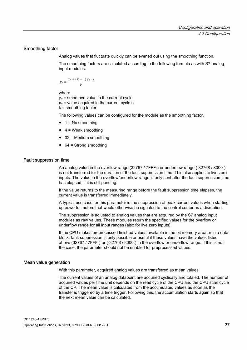
Smoothing factor Analog values that fluctuate quickly can be evened out using the smoothing function.
The smoothing factors are calculated according to the following formula as with S7 analog input modules.
1y x k yk
nn n
=+ − −( )1
where yn = smoothed value in the current cycle xn = value acquired in the current cycle n k = smoothing factor
The following values can be configured for the module as the smoothing factor.
● 1 = No smoothing
● 4 = Weak smoothing
● 32 = Medium smoothing
● 64 = Strong smoothing
Fault suppression time An analog value in the overflow range (32767 / 7FFFh) or underflow range (-32768 / 8000h) is not transferred for the duration of the fault suppression time. This also applies to live zero inputs. The value in the overflow/underflow range is only sent after the fault suppression time has elapsed, if it is still pending.
If the value returns to the measuring range before the fault suppression time elapses, the current value is transferred immediately.
A typical use case for this parameter is the suppression of peak current values when starting up powerful motors that would otherwise be signaled to the control center as a disruption.
The suppression is adjusted to analog values that are acquired by the S7 analog input modules as raw values. These modules return the specified values for the overflow or underflow range for all input ranges (also for live zero inputs).
If the CPU makes preprocessed finished values available in the bit memory area or in a data block, fault suppression is only possible or useful if these values have the values listed above (32767 / 7FFFh) or (-32768 / 8000h) in the overflow or underflow range. If this is not the case, the parameter should not be enabled for preprocessed values.
Mean value generation With this parameter, acquired analog values are transferred as mean values.
The current values of an analog datapoint are acquired cyclically and totaled. The number of acquired values per time unit depends on the read cycle of the CPU and the CPU scan cycle of the CP. The mean value is calculated from the accumulated values as soon as the transfer is triggered by a time trigger. Following this, the accumulation starts again so that the next mean value can be calculated.
Configuration and operation 4.2 Configuration
CP 1243-1 DNP3 38 Operating Instructions, 07/2013, C79000-G8976-C312-01
The mean value can also be calculated if the transmission of the analog value message is triggered by a request from the communications partner. The duration of the mean value calculation period is then the time from the last transmission (for example triggered by the trigger) to the time of the request. Once again, the accumulation restarts so that the next mean value can be calculated.
If the acquired analog value is in the overflow range (32767 / 7FFFh) or underflow range (-32768 / 8000h), this value can either be taken into account immediately in the calculation of the mean value or it can be suppressed for a specific period for the calculation of the mean value. The required response can be decided with the Fault suppression time parameter:
● Fault suppression time = 0
Acquisition of a value in the overflow or underflow range results in the mean calculation being stopped immediately. The value 32767 / 7FFFh or -32768 / 8000h is saved as an invalid mean value for the current mean value calculation period and sent when the next analog value frame is triggered. The calculation of a new mean value is then started. If the analog value remains in the overflow or underflow range, this new value is again saved immediately as an invalid mean value and sent when the next frame is triggered.
● Fault suppression time > 0
If the acquired analog value is in the overflow or underflow range, the bad values are excluded from the calculation of the mean value for a maximum time as defined by the Fault suppression time. If this time is exceeded, the value 32767 / 7FFFh or -32768 / 8000h is saved as an invalid mean value and sent when the next analog value frame is triggered. The procedure is identical in each new averaging period; in other words, bad values are again suppressed for the duration of the fault suppression time.
The duration of the fault suppression time also indirectly decides the proportion of invalid values per averaging period. If the mean value is formed, for example in a cycle of 15 minutes, and the fault suppression time is set to 5 minutes, this means that the mean value is only transferred as invalid if more than 33% of the acquired analog values are in the overflow or underflow range in the current averaging period.

CP 1243-1 DNP3 Operating Instructions, 07/2013, C79000-G8976-C312-01 39
Diagnostics, servicing, maintenance 55.1 Diagnostics options
The following diagnostics options are available:
LEDs of the module For information on the LED displays, refer to the section LEDs (Page 16).
STEP 7: The "Diagnostics" tab in the Inspector window Here, you can obtain the following information on the selected module:
● Entries in the diagnostics buffer of the CPU
● Information on the online status of the module
STEP 7: Diagnostics functions in the "Online > Online and diagnostics" menu Here, you can obtain static information on the selected module:
● General information on the module
● Diagnostics status
● Information on the Ethernet interface:
– Network
– Ethernet interface
– Statistics
You will find further information on the diagnostics functions of STEP 7 in the STEP 7 information system.
TeleService Via a TeleService connection, you can read diagnostics information from the CP from an engineering station on which the project with the CP is stored.
You will find further information on TeleService in the STEP 7 information system.
Enabling the communications service for TeleService and online diagnostics If you want to operate TeleService or online diagnostics with the station via a LAN, in other words via the CP, you need to enable the "TeleService" communication type, see section Information on configuring individual parameters (Page 33).

Diagnostics, servicing, maintenance 5.2 Downloading firmware
CP 1243-1 DNP3 40 Operating Instructions, 07/2013, C79000-G8976-C312-01
5.2 Downloading firmware
New firmware versions If a new firmware version is available for the module, you will find this on the Ethernet pages of the Siemens Automation Customer Support under the following ID:
68853485 (http://support.automation.siemens.com/WW/view/en/68853485)
On the Internet page, select the "Entry list" tab and the "Download" entry type. You will find the firmware file and a description of the procedure there.
5.3 Module replacement
Module replacement The STEP 7 project data of the CP is stored on the local CPU. If there is a fault on the device, this allows simple replacement of this communications module without needing to load the project data to the station again.
When the station starts up again, the new CP reads the project data from the CPU.
CAUTION Read the system manual "S7-1200 Programmable Controller"
Prior to installation, connecting up and commissioning, read the relevant sections in the system manual "S7-1200 Programmable Controller" (refer to the documentation in the Appendix).
When installing and connecting up, keep to the procedures described in the system manual "S7-1200 Programmable Controller".
Make sure that the power supply is turned off when installing/uninstalling the devices.

CP 1243-1 DNP3 Operating Instructions, 07/2013, C79000-G8976-C312-01 41
Technical specifications 6
Table 6- 1 Technical specifications of the CP 1243-1
Technical specifications Order number 6GK7 243-1JX30-0XE0 Attachment to Industrial Ethernet Quantity 1 Design RJ-45 jack Properties 100BASE-TX, IEEE 802.3-2005, half duplex/full duplex, autocrossover,
autonegotiation, galvanically isolated Transmission speed 10/100 Mbps Permitted cable lengths (Ethernet) (Alternative combinations per length range) * 0 ... 55 m Max. 55 m IE TP Torsion Cable with IE FC RJ45 Plug 180
Max. 45 m IE TP Torsion Cable with IE FC RJ45 + 10 m TP Cord via IE FC RJ45 Outlet
0 ... 85 m Max. 85 m IE FC TP Marine/Trailing/Flexible/FRNC/Festoon/Food Cable with IE FC RJ45 Plug 180
Max. 75 m IE FC TP Marine/Trailing/Flexible/FRNC/Festoon/Food Cable + 10 m TP Cord via IE FC RJ45 Outlet
0 ... 100 m Max. 100 m IE FC TP Standard Cable with IE FC RJ45 Plug 180 Max. 90 m IE FC TP Standard Cable + 10 m TP Cord via IE FC RJ45 Outlet
Electrical data Power supply From the S7-1200 backplane bus 5 VDC Current consumption (typical) From the S7-1200 backplane bus 250 mA Effective power loss (typical) From the S7-1200 backplane bus 1.25 W Permitted ambient conditions
During operation with the rack installed horizontally
-20 ℃ to +60 ℃
During operation with the rack installed vertically
-20 ℃ to +50 ℃
During storage -40 ℃ to +70 ℃
Ambient temperature
During transportation -40 ℃ to +70 ℃ Relative humidity During operation ≤ 95 % at 25 °C, no condensation Design, dimensions and weight Module format Compact module for S7-1200, single width Degree of protection IP20 Weight 122 g Dimensions (W x H x D) 30 x 110 x 75 mm
Technical specifications
CP 1243-1 DNP3 42 Operating Instructions, 07/2013, C79000-G8976-C312-01
Technical specifications Installation options Standard DIN rail
Switch panel Product functions **
* For details, refer to the IK PI catalog, cabling technology **You will find further characteristics and performance data in the section Application and properties (Page 9).
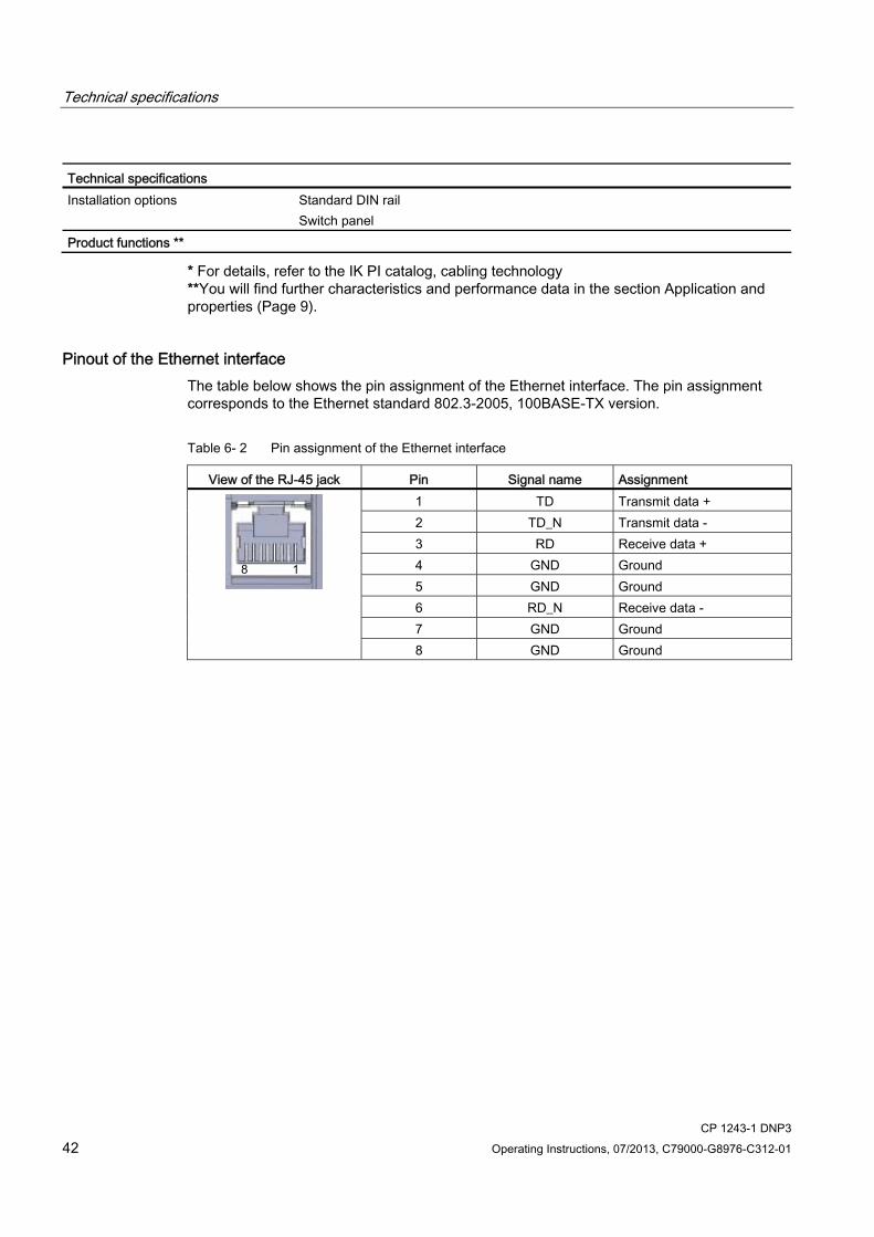
Pinout of the Ethernet interface The table below shows the pin assignment of the Ethernet interface. The pin assignment corresponds to the Ethernet standard 802.3-2005, 100BASE-TX version.
Table 6- 2 Pin assignment of the Ethernet interface
View of the RJ-45 jack Pin Signal name Assignment 1 TD Transmit data + 2 TD_N Transmit data - 3 RD Receive data + 4 GND Ground 5 GND Ground 6 RD_N Receive data - 7 GND Ground
8 GND Ground

CP 1243-1 DNP3 Operating Instructions, 07/2013, C79000-G8976-C312-01 43
Approvals A
Approvals issued
Note Issued approvals on the type plate of the device
The specified approvals apply only when the corresponding mark is printed on the product. You can check which of the following approvals have been granted for your product by the markings on the type plate.
Current approvals on the Internet SIMATIC NET products are regularly submitted to the relevant authorities and approval centers for approvals relating to specific markets and applications.
You will also find the current approvals for the product on the Internet pages of Siemens Automation Customer Support under the following entry ID:
68853485 (http://support.automation.siemens.com/WW/view/en/68853485) → "Entry list" tab, entry type "Certificates"
Other approvals SIMATIC NET products are regularly submitted to the relevant authorities and approval centers for approvals relating to specific markets and applications.
If you require a list of the current approvals for individual devices, consult your Siemens contact or check the Internet pages of Siemens Automation Customer Support:
45605894 (http://support.automation.siemens.com/WW/view/en/45605894)
Under this entry, go to the relevant product and select the following settings: "Entry list" tab > entry type "Certificates".
The CP has the following approvals and meets the following standards:
EC declaration of conformity The CP meets the requirements and safety objectives of the following EU directives and it complies with the harmonized European standards (EN) for programmable logic controllers which are published in the official documentation of the European Union.

Approvals
CP 1243-1 DNP3 44 Operating Instructions, 07/2013, C79000-G8976-C312-01
● EC directive 2006/95/EEC "Electrical Equipment Designed for Use within Certain Voltage Limits" (Low Voltage Equipment Directive)
● EN 60950-1 Information Technology Equipment - Safety
● EC Directive 2004/108/EC "Electromagnetic Compatibility" (EMC Directive)
– Emission EN 61000-6-4:2007: Industrial area
– Immunity EN 61000-6-2:2005: Industrial area
The EC Declaration of Conformity is available for all responsible authorities at:
Siemens Aktiengesellschaft Industry Automation Industrielle Kommunikation SIMATIC NET Postfach 4848 D-90327 Nürnberg Germany
You will find the EC Declaration of Conformity for this product on the Internet at the following address:
68853485 (http://support.automation.siemens.com/WW/view/en/68853485) → tab "Entry list"
Filter settings: Entry type: "Certificates" Certificate Type: "Declaration of Conformity" Search items(s): <name of the module>
ATEX ATEX approval: II 3 G Ex nA IIC T4 Gc
Relevant standards:
● EN 60079-0:2006: Potentially explosive atmosphere - general requirements
● EN 60079-15:2005: Electrical apparatus for explosive gas atmospheres; type of protection 'n'
The device is suitable for use in environments with pollution degree 2.
The device is suitable for use only in environments that meet the following conditions:
● Class I, Division 2, Group A, B, C, D and areas where there is no risk of explosion
● Class I, Zone 2, Group IIC and areas where there is no risk of explosion

Approvals
CP 1243-1 DNP3 Operating Instructions, 07/2013, C79000-G8976-C312-01 45
WARNING Installation guidelines
The product meets the requirements if you keep to the following during installation and operation: The notes in the section Important notes on using the device (Page 21) The installation instructions in the document /1/ (Page 49)
Over and above this, the following conditions must be met for the safe deployment of the CP:
● Install the modules in a suitable enclosure with degree of protection of at least IP54 to EN 60529 and take into account the environmental conditions for operation of the devices.
● If the rated temperatures of 70°C at the cable entry or 80°C at the branching point of the wires are exceeded, the permitted temperature range of the selected cable must be suitable for the actual measured temperatures.
● Measures must be taken to prevent the rated voltage being exceeded by more than 40% due to transient disturbances.
cULus HAZ.LOC. Underwriters Laboratories Inc. meets
● Underwriters Laboratories, Inc.: UL 508 Listed (industrial control devices)
● UL 1604 (Hazardous Location)
● Canadian Standards Association: CSA C22.2 No 142 (process control equipment)
● CSA C22.2 No. 213 (Hazardous Location)
APPROVED for Use in:
● Cl. 1, Div. 2, GP. A, B, C, D T4A; Ta = -20 °C...60 °C
● Cl. 1, Zone 2, GP. IIC T4; Ta = -20 °C...60 °C
FM Factory Mutual Research (FM): Approval Standard Class Number 3600 and 3611 approved for use in: Class I, Division 2, Group A, B, C, D, Temperature Class T4A, Ta = 60 °C Class I, Zone 2, Group IIC, Temperature Class T4, Ta = 60 °C
C-Tick The CP meets the requirements of the AS/NZS 2064 standards (Class A)

Approvals
CP 1243-1 DNP3 46 Operating Instructions, 07/2013, C79000-G8976-C312-01
CP 1243-1 DNP3 Operating Instructions, 07/2013, C79000-G8976-C312-01 47
Dimension drawings B
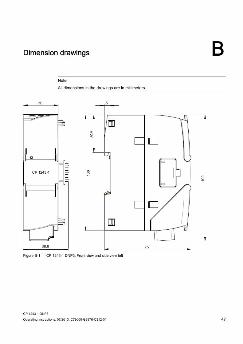
Note
All dimensions in the drawings are in millimeters.
Figure B-1 CP 1243-1 DNP3: Front view and side view left

Dimension drawings
CP 1243-1 DNP3 48 Operating Instructions, 07/2013, C79000-G8976-C312-01
Figure B-2 CP 1243-1 DNP3: View from above
CP 1243-1 DNP3 Operating Instructions, 07/2013, C79000-G8976-C312-01 49
Documentation references C
Where to find Siemens documentation ● You will find the order numbers for the Siemens products of relevance here in the
following catalogs:
– SIMATIC NET Industrial Communication / Industrial Identification, catalog IK PI
– SIMATIC Products for Totally Integrated Automation and Micro Automation, catalog ST 70
You can request the catalogs and additional information from your Siemens representative.
● You will find SIMATIC NET manuals on the Internet pages of Siemens Automation Customer Support: Link to Customer Support (http://support.automation.siemens.com/WW/view/en)
Enter the entry ID of the relevant manual as the search item. The ID is listed below some of the reference entries in brackets.
As an alternative, you will find the SIMATIC NET documentation on the pages of Product Support:
10805878 (http://support.automation.siemens.com/WW/view/en/10805878)
Go to the required product group and make the following settings:
"Entry list" tab, Entry type "Manuals / Operating Instructions"
You will find the documentation for the SIMATIC NET products relevant here on the data medium that ships with some products:
– Product CD / product DVD or
– SIMATIC NET Manual Collection
/1/ SIMATIC S7-1200 Programmable Controller System Manual Siemens AG order number: 6ES7298-8FA30-8BH0 Entry ID: 36932465 (http://support.automation.siemens.com/WW/view/en/36932465)

Documentation references 0 /2/
CP 1243-1 DNP3 50 Operating Instructions, 07/2013, C79000-G8976-C312-01
/2/ SIMATIC NET CP 1243-1 DNP3 Operating Instructions Siemens AG entry ID: 68853485 (http://support.automation.siemens.com/WW/view/en/36932465)

CP 1243-1 DNP3 Operating Instructions, 07/2013, C79000-G8976-C312-01 51
Index
A Analog value preprocessing, 36
C Configuring communication, 28 Connection resources, 13
D Datapoint configuration, 28 Datapoint editor, 30 Dimensions, 24 DNP3 - L5, 31 DNP3 addressing, 29 DNP3 device profile, 14 DNP3 implementation level, 31 DNS server, 29
E E-mail
Configuration, 30 Number of messages, 14
Ethernet interface Assignment, 42
F Feedback, 33 Firmware version, 3
G Glossary, 5
H Hardware product version, 3
I IP address (master), 29 IP configuration
IPv4, IPv6, 12
M Message editor, 30
O Online diagnostics, 39 Operating states, 17
P PG/OP connections, 13 Product name, 4 PUT/GET, 13
R Redundant control system, 28 Replacing a module, 40
S S7 connections, 33 Safety notices, 21 Security events, 12 Security functions, 29 Service & Support, 5 SIMATIC NET glossary, 5 STEP 7 version, 27
T TeleService, 39 Time-of-day synchronization, 35 Training, 5

Index
CP 1243-1 DNP3 52 Operating Instructions, 07/2013, C79000-G8976-C312-01