1 is up to 30% stronger 1 2 3 than competitive designs f or longer … motor gerotor med.pdf ·...
TRANSCRIPT

28
HBFEATURES2 3
45
SPECIFICATIONS
1Heavy-Duty Drive Link is up to 30% strongerthan competitive designs for longer life.
Three-Zone Orbiting Valve precisely meters oil toproduce exceptional volumetric efficiency.
Standard Case Drain increases shaft seal life byreducing pressure on seal.
Rubber Energized Steel Face Seal does notextrude or melt under high pressure or hightemperature.
Forced Drive Link Lubrication reduces wear andpromotes longer life from motor.
The HB Series motor is the leader in its class, offering highefficiency and durability. The three-zone orbiting valve, lami-nated manifold and Roller Stator® motor work harmoniously toproduce high overall efficiencies over a wide range of operatingconditions. The standard case drain increases shaft seal life byreducing internal pressures experienced by the seal. Case oilleakage is also directed across all driveline components, increas-ing motor life. An internal drain option is also available. At theheart of the motor is a heavy-duty drivelink, offering 30% moretorque capacity than competitive designs. These features makethe HB Series motor the preferred choice for applications requir-ing peak efficiency for continuous operation.
1
2
3
4
5
050080090110125160200250300400
10 1214 1716 2020 2520 2520 2520 2520 2520 2520 25
3000 3500 40003000 3500 40003000 3500 40003000 3500 40003000 3500 40003000 3500 40003000 3500 40003000 3500 40003000 3500 40002500 2750 3000
3.24.65.46.87.710.012.515.517.924.9
680 830700 950680 840680 850580 740460 580370 460290 370250 320180 230
1 2 1 2 1 2 3
1200 14001700 19752000 24002650 31003000 35003975 45505050 58006250 71007200 82508400 9050
1 2
Code
Displacement(in3/rev)
Max. Speed (RPM) - 1)Cont 2)Inter.
Max. Flow (GPM) - 1)Cont 2)Inter.
Max. Torque (lb-in) - 1)Cont 2)Inter.
Max. Pressure (PSI) - 1)Cont 2)Inter. 3)Peak

29
HB
Note: Performance data istypical. Performance ofproduction units varies slightlyfrom one motor to another.
Torque, lb-in (Nm)Speed, RPM
Areas within white representmaximum motor efficiencies.
DO NOT operate at maximumpressure and maximum flowsimultaneously.
PERFORMANCE050 3.2 in3/rev
080 4.6 in3/rev
Tested at 129°F with an oilviscosity of 213 SUS

30
HB
Note: Performance data istypical. Performance ofproduction units varies slightlyfrom one motor to another.
Torque, lb-in (Nm)Speed, RPM
Areas within white representmaximum motor efficiencies.
DO NOT operate at maximumpressure and maximum flowsimultaneously.
090 5.4 in3/rev
PERFORMANCE
110 6.8 in3/rev
Tested at 129°F with an oilviscosity of 213 SUS

31
HB
Note: Performance data istypical. Performance ofproduction units varies slightlyfrom one motor to another.
Torque, lb-in (Nm)Speed, RPM
Areas within white representmaximum motor efficiencies.
DO NOT operate at maximumpressure and maximum flowsimultaneously.
PERFORMANCE125 7.7 in3/rev
160 10.0 in3/rev
Tested at 129°F with an oilviscosity of 213 SUS

32
HB
Note: Performance data istypical. Performance ofproduction units varies slightlyfrom one motor to another.
Torque, lb-in (Nm)Speed, RPM
Areas within white representmaximum motor efficiencies.
DO NOT operate at maximumpressure and maximum flowsimultaneously.
200 12.5 in3/rev
PERFORMANCE
250 15.5 in3/rev
Tested at 129°F with an oilviscosity of 213 SUS

33
HB
Note: Performance data istypical. Performance ofproduction units varies slightlyfrom one motor to another.
Torque, lb-in (Nm)Speed, RPM
Areas within white representmaximum motor efficiencies.
DO NOT operate at maximumpressure and maximum flowsimultaneously.
PERFORMANCE300 17.9 in3/rev
400 24.9 in3/rev
Tested at 129°F with an oilviscosity of 213 SUS

34
300A0 2-Hole with End Ports
.522
.514
Ø 4.187
2.08 Max.
1.91 Max..57
.210
.205
3.2503.242
.12.06
Ø 4.18722.50
450
5.19 Max.
2.08 Max.
1.91 Max.
5.19 Max.
SAE A FLANGE
D
A7
A2 4-Hole with End Ports A8
D
.522
.514
D
A4 6-Hole with End Ports A9
D is on page 36
HOUSINGS
2-Hole with Side Ports
4-Hole with Side Ports
.57.210.205
3.2503.242
.12.06
.57.210.205
3.2503.242
.12.06
Ø 4.18722.50
450
5.19 Max.
2.08 Max.
1.91 Max.
.522
.514
6-Hole with Side Ports

35
300HOUSINGS
4.9994.994
.10 Min.
1.42
1.62
3.2503.247
5.12 Max.
.522
.514
5.45 Max.
Ø 5.812450
3.78 (4) 3/8”-16 UNC-2B.63 Min. Deep
3.12 Max.
3.56
Ø 3.250
3.12 Max.
450
B0 2-Hole with End Ports B7 2-Hole with Side Ports
W2 4-Hole with End Ports W8 4-Hole with Side Ports
F2 4-Hole with End Ports F8 4-Hole with Side Ports
SAE B FLANGE
2.37 Max. 2.37 Max.
2.00
6.96 Max.
5.75
.522
.514
.12.06
3.9993.992
.125B
E
WHEEL MOUNT
4-HOLE SQUARE MOUNT
F
B is on page 36
E is on page 37
F is on page 37

36
300
9,000
8,000
7,000
6,000
5,000
4,000
3,000
2,000
1,000lbs.
4,000
3,500
3,000
2,500
2,000
1,500
1,000
500DaN
-3 -2 -1 0 1 2 3 4 5 in
-75 -50 -25 0 25 50 75 100 125 mm
9,000
8,000
7,000
6,000
5,000
4,000
3,000
2,000
1,000lbs.
3,500
3,000
2,500
2,000
1,500
1,000
500DaN
-4 -3 -2 -1 0 1 2 3 4 in.
-100 -75 -50 -25 0 25 50 75 100 mm
SAE A & B FLANGE
Bearing
Shaft
1000 lbs
ALLOWABLE BEARING AND SHAFT LOADS
B WeightCode in lbs
050 7.68 22.2
080 7.82 22.7090 7.90 22.9110 8.04 23.4125 8.14 23.7160 8.36 24.4200 8.61 25.2250 8.91 26.1300 9.15 27.0400 9.86 29.1
Bearing Curve: The bearing curve represents allowable bearing loadsbased on ISO 281 bearing capacity for an L10 life of 2,000 hours at 100RPM. Radial loads for speeds other than 100 RPM may be calculatedusing the multiplication factor table located on page 24.
WHEEL MOUNT
D WeightCode in lbs
050 7.68 19.5
080 7.82 20.0090 7.90 20.2110 8.04 20.7125 8.14 21.0160 8.36 21.7200 8.61 22.5250 8.91 23.4300 9.15 24.3400 9.86 26.4
Bearing
Shaft
SAE “B” Flange
1000 lbs
1000 lbs
1000 lbs
SAE “A” Flange
LENGTH AND WEIGHT TABLES
TECHNICAL
HB motor weights vary ± 2 lbs depending upon motorconfiguration.Subtract .71 in. from dimension for motors with sideports 5, 6, & 7 and end ports 1 & 2

37
3009,000
8,000
7,000
6,000
5,000
4,000
3,000
2,000
1,000lbs.
4,000
3,500
3,000
2,500
2,000
1,500
1,000
500DaN
-4 -3 -2 -1 0 1 2 3 in.
-100 -75 -50 -25 0 25 50 75 mm
4-HOLE
1000 lbs
1000 lbs
Bearing
Shaft
01 1.75 3.21 1.63
02 1.93 3.39 1.81
22 2.58 4.04 2.4620 2.40 3.87 2.29
23 2.23 3.69 2.11
10 1.93 3.39 1.8112 2.17 3.63 2.0521 2.40 3.87 2.2907 2.46 3.93 2.3515 1.99 3.45 1.8708 2.46 3.93 2.35
Code A & B Flange
in
Wheel Mount
in
4-Hole
in
Shaft Lengths vary± .030 in
SHAFT LENGTHS
G
ALLOWABLE BEARING AND SHAFT LOADS
� � E� Weight�� Code� in� lbs�� �� 050� 6.22� 25.3�
� 080� 6.36� 25.7�� 090� 6.41� 25.9�� 110� 6.55� 26.5�� 125� 6.64� 26.7�� 160� 6.87� 27.4�� 200� 7.12� 28.3�� 250� 7.42� 29.1�� 300� 7.66� 30.0�� 400� 8.37� 32.1
Bearing Curve: The bearing curve represents allowable bearing loadsbased on ISO 281 bearing capacity for an L10 life of 2,000 hours at 100RPM. Radial loads for speeds other than 100 RPM may be calculatedusing the multiplication factor table located on page 24.
F WeightCode in lbs
050 7.80 18.4
080 7.94 18.9090 8.02 19.1110 8.16 19.6125 8.26 19.9160 8.48 20.6200 8.73 21.4250 9.03 22.3300 9.27 23.2400 9.98 25.3
Wheel Mount
4-Hole Square Mount
LENGTH AND WEIGHT TABLES
HB motor weights vary ± 2 lbs depending upon motorconfiguration.Subtract .71 in. from dimension for motors with sideports 5, 6, & 7 and end ports 1 & 2
TECHNICAL

38
30030°
1.761.020.970
.70 Min.
.24
.999
.998
5/16”-18 UNC
1.1101.101
.251
.250.251.250
25mm Straight1” Straight1” Straight Ext.
1210*15
MountingFlange
Max. Torque: 5850 lb-in G MountingFlange Mounting
Flange
MountingFlange
MountingFlange
MountingFlange
MountingFlange
MountingFlange
G
G
G
GG
G
M8x1.25
.277
.276
.314
.313
1.82
.984
.983
.38
.63 Min.
1.2811.280
1.2181.168
30°
G
Max. Torque: 5580 lb-in
.276
.274
.394
.392
2.14
.63 Min.
.46
1.2851.235
1.90
Ø .06Wire Ring
M8x1.25
1.2601.259
1.31Wire Ring
1.3721.359
32mm Straight32mm Straight Ext.
21*08
Max. Torque: 7804 lb-in
1-1/4” Straight1-1/4” Straight Ext.
20*07
1.3881.376
.276
.274
.314
.313
1.4751.425
1.90
2.14
.33
.83 Min.
1.2501.249
5/8”-18 Bolt
5/8” Lock Washer
15°
Max. Torque: 7804 lb-in
Ø .06Wire Ring
1.31Wire Ring
Note: A slotted nut is standard on this shaft.
.957
.907
.314
.313
.276
.274
1”-20 UNEF
1.2501.249
.17
.210
.190
.75
1:8 Taper
1.37
15°
.15
1 1/4” Tapered22
5/16”-18 UNC
13 Tooth 16/32 Pitch Std.ANSI B92.1-1996 Spline
300
Max. Torque: 7804 lb-in
13 Tooth Spline01
Max. Torque: 1500 lb-in
.71
.874
.872
1.58
.996
.992
.70 Min.
1.00 Min.
1.00-6-B Spline (SAE J499 Std.)
.245
.243
5/16”-18 UNC
30°
Ø .810
02 6-B Spline 14 Tooth Spline23
Max. Torque: 3800 lb-in
1.43 Min.
1.90
2.14
5/8”-18 UNF
1.2491.245
.83 Min.
14 Tooth 12/24 pitch Std.ANSI B92.1-1996 Spline
15°
Max. Torque: 7804 lb-in
Ø .06Wire Ring
1.31Wire Ring
*Speed Sensor Component
G is on page 37
SHAFTS
39
300PORTS
.19
Q
V
.20
.75
1.12
Q
.97
Q - Case Drain
V - Valve Cavity
.55
1.13
.47
V
Q
1.22
.66
.72
.52.85
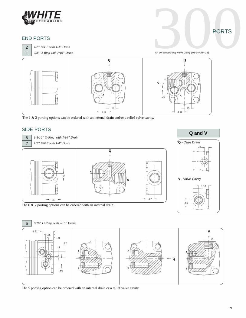
D- 10 Series/2-way Valve Cavity (7/8-14 UNF-2B)
A
B
A
B
A
B
B
A
B B
A A
D
D
Q and V
.50
21
1/2” BSP.F with 1/4” Drain
7/8” O-Ring with 7/16” Drain
Q
The 1 & 2 porting options can be ordered with an internal drain and/or a relief valve cavity.
67
1-1/16” O-Ring with 7/16” Drain
1/2” BSP.F with 1/4” Drain
The 6 & 7 porting options can be ordered with an internal drain.
5 9/16” O-Ring with 7/16” Drain
The 5 porting option can be ordered with an internal drain or a relief valve cavity.
END PORTS
SIDE PORTS
.75
1.12
.97

40
300PORTS
.46
.72
.58
1.76
HB ROTATION SELECTION
A AB B
SIDE PORTS
21
1/2” BSP.F with 1/4” Drain
7/8” O-Ring with 7/16” Drain D- 10 Series/2-way Valve Cavity (7/8-14 UNF-2B)
The 1 & 2 porting options can be ordered with an internal drain and/or a relief valve cavity.
S
R
A
B D
A
B
R
3 1/2” BSP.F with 1/4” Drain
The 3 porting option can be ordered with an internal drain.
1.91
R
A
B
.65
1.66.83
1.26
M10 x 1.5; .43Min. Deep
.871.72 .43 Min.
.61 Min.
2.13
R and S
R - Case Drain S - Valve Cavity
1.17 1.36
.53

41
300ORDERING INFORMATION
Code
A
*B
*C
*D
*E
*F
*G
*J
*L
Options
None
Relief Valve Cavity
1000 psi Relief Valve Installed
1250 psi Relief Valve Installed
1500 psi Relief Valve Installed
1750 psi Relief Valve Installed
2000 psi Relief Valve Installed
2500 psi Relief Valve Installed
3000 psi Relief Valve Installed
Housing
2-Hole End Ports (S)
2-Hole Side Ports (S)
4-Hole End Ports (S)
4-Hole Side Ports (S)
6-Hole End Ports
6-Hole Side Ports
2-Hole End Ports
2-Hole Side Ports
4-Hole End Ports
4-Hole Side Ports
4-Hole End Ports
4-Hole Side Ports
Code
A0
A7
A2
A8
A4
A9
B0
B7
W2
W8
F2
F8
* Available with end ports 1& 2 and side ports 1, 2, & 5
** Available with A0, A2, A7, & A8 housings only and must use speedsensor shafts
(S) Speed Sensor Components
Code
5
6
7
1
2
3
Side Ports
9/16" O-ring
1800 Ports1-1/16" O-ring
1800 Ports1/2" BSP.F
Offset Ports7/8" O-ring
Offset Ports1/2" BSP.F
Manifold Ports1/2" BSP.F
Code
1
2
End Ports
Aligned Ports7/8" O-ring
Aligned Ports1/2" BSP.F
Shafts
13 Tooth Spline
6-B Spline
1-1/4" Tapered
1-1/4" Straight
14 Tooth Spline
1" Straight
25mm Straight
32mm Straight
1-1/4" Straight (S)
1" Straight (S)
32mm Straight (S)
Code
01
02
22
20
23
10
12
21
07
15
08
DISPLACEMENT
300SHAFTHOUSINGS
PORTS
SERIES
Code
050080090110125160200250300400
Displacements
3.2 in3/rev4.6 in3/rev5.4 in3/rev6.8 in3/rev7.7 in3/rev10.0 in3/rev12.5 in3/rev15.5 in3/rev17.9 in3/rev24.9 in3/rev
NOTE: To complete the 3 digit housing
code, a housing and port option must be
entered. A side port housing option must
use side port connections, and a end port
housing option must use end port
connections.
(Example: W82 = A wheel mount motor
with 1/2" BSP.F threading)
Code
A
B
C
D
Z
Options
Dark Metallic Gray
Dark Metallic Gray(Unpainted Flange Face)
Black
Black (Unpainted Flange Face)
No Paint
PAINT
CAVITY
Code
A
B
C
**W
**X
**Y
**Z
ADD ONS
Options
Standard
Lock Nut
Solid Hex Nut
4-Pin Male WeatherpackConnector (Dual) (S)
4-Pin M12 Male Connector (Dual) (S)
3-Pin Male WeatherpackConnector (Single) (S)
4-Pin M12 Male Connector (Single) (S)
MISCELLANEOUS
OPTIONS
Code
AA
AB
AC
AD
Options
None
Internal Drain
Freeturning Rotor
Internal Drain and Freeturning Rotor
42
312TECHNICAL
(4) 1/2”-13 UNC.75 Min. Deep
7.40 Max.
10,000
9,000
8,000
7,000
6,000
5,000
4,000
3,000
2,000
1,000lbs.
4,000
3,500
3,000
2,500
2,000
1,500
1,000
500DaN
-4 -3 -2 -1 0 1 2 3 4 5 in.
-100 -75 -50 -25 0 25 50 75 100 125 mm
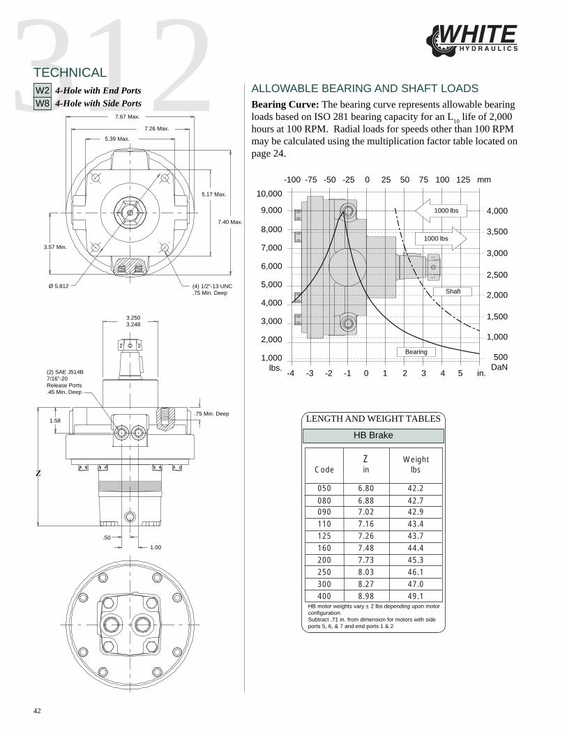
ALLOWABLE BEARING AND SHAFT LOADSW2 4-Hole with End PortsW8 4-Hole with Side Ports
7.67 Max.
3.57 Min.
5.17 Max.
5.39 Max.
7.26 Max.
Ø 5.812
(2) SAE J514B7/16”-20Release Ports.45 Min. Deep
1.00
.50
1.58.75 Min. Deep
3.2503.248
Z
1000 lbs
1000 lbs
Bearing
Shaft
Bearing Curve: The bearing curve represents allowable bearingloads based on ISO 281 bearing capacity for an L10 life of 2,000hours at 100 RPM. Radial loads for speeds other than 100 RPMmay be calculated using the multiplication factor table located onpage 24.
Z WeightCode in lbs
050 6.80 42.2
080 6.88 42.7090 7.02 42.9110 7.16 43.4125 7.26 43.7160 7.48 44.4200 7.73 45.3250 8.03 46.1300 8.27 47.0400 8.98 49.1
HB Brake
LENGTH AND WEIGHT TABLES
HB motor weights vary ± 2 lbs depending upon motorconfiguration.Subtract .71 in. from dimension for motors with sideports 5, 6, & 7 and end ports 1 & 2

43
312CAUTION! - White Hydraulics motors/brakes are intended to operate as static or parking brakes. System circuitrymust be designed to bring the load to a stop before applying the brake.
CAUTION! - Because it is possible for some large displacement motors to overpower the brake, it is critical that themaximum system pressure be limited for these applications. Failure to do so could cause serious injury or death.When choosing a motor/brake for an application, consult the performance chart for the series and displacement chosenfor the application to verify that the maximum operating pressure of the system will not allow the motor to producemore torque than the maximum rating of the brake. Also, it is vital that the system relief be set low enough to insurethat the motor is not able to overpower the brake.
To ensure proper operation of the brake, case drain back pressure must be maintained at 500 psi or less. Case drainback pressure above 500 psi can result in erratic operation of the brake. To avoid potential problems with the opera-tion of the brake, a separate case drain line is recommended. Use of the internal drain option is not recommended dueto the possibility of return line pressure spikes. A simple schematic of a system utilizing a motor/brake is shown inFigure A below. Although maximum brake release pressure may be used for an application, a 500 psi pressure reduc-ing valve is recommended to promote maximum life for the brake release piston seals. To achieve proper brakerelease operation, it is necessary to bleed out any trapped air and fill brake release cavity and hoses before all connec-tions are tightened. To facilitate this operation, all motor/brakes feature two release ports. One or both of these portsmay be used to release the brake in the unit. Motor/brakes should be configured so that the release ports are near thetop of the unit in the installed position. Once all system connections are made, one release port must be opened toatmosphere and the brake release line carefully charged with fluid until all air is removed from the line and motor/brake release cavity. When this has been accomplished the port plug or secondary release line must be reinstalled. Inthe event of a pump or battery failure, an external pressure source may be connected to the brake release port torelease the brake, allowing the machine to be moved.
OPERATING RECOMMENDATIONS
CAUTION: It is vital that all operating recommendations be followed. Failure to do so could result in injury or death.
Typical motor/brake schematic
Figure A
44
312SHAFTS
Ø 0.6Wire Ring
.83 Min.
5/8”-18 UNF
1.2501.249
.32
1.4751.425
1.90
2.14
*4.19
.394
.392.276.274
*3.96
2.14
1.891.2851.235
30o
1-1/8”-18 UNEF Slotted Hex Nut
1.4751.425
1.5001.499
*4.56
.20
1:8 Taper
.75
.17
1.72
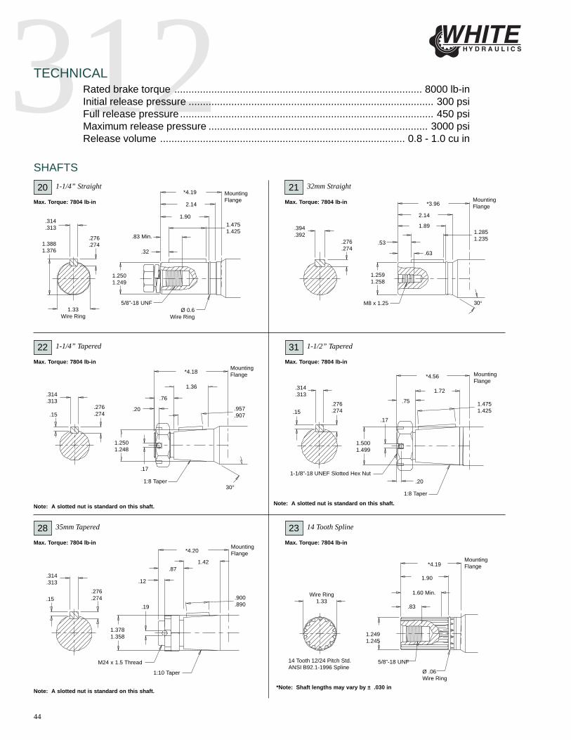
*Note: Shaft lengths may vary by ± .030 in
14 Tooth 12/24 Pitch Std.ANSI B92.1-1996 Spline
Wire Ring1.33
1.90
1.2491.245
.83
*4.19
1.60 Min.
Ø .06Wire Ring
5/8”-18 UNF
*4.20
1.42.87
.12
.900
.890.19
1.3781.358
M24 x 1.5 Thread
1:10 Taper
.15
Note: A slotted nut is standard on this shaft.
*4.18
.20
.76
30°1:8 Taper
.17
1.2501.248
.957
.907
1.36
.53
.63
1.2591.258
M8 x 1.251.33
Wire Ring
1.3881.376
.276
.274
.314
.313
Rated brake torque ....................................................................................... 8000 lb-inInitial release pressure ...................................................................................... 300 psiFull release pressure ......................................................................................... 450 psiMaximum release pressure ............................................................................. 3000 psiRelease volume ...................................................................................... 0.8 - 1.0 cu in
TECHNICAL
1-1/4” Straight20Max. Torque: 7804 lb-in
MountingFlange
32mm Straight21Max. Torque: 7804 lb-in Mounting
Flange
1-1/4” Tapered22Max. Torque: 7804 lb-in
MountingFlange
31Max. Torque: 7804 lb-in
MountingFlange
.276
.274
.314
.313
.15
.276
.274
.314
.313
Note: A slotted nut is standard on this shaft.
1-1/2” Tapered
35mm Tapered28Max. Torque: 7804 lb-in
MountingFlange
23Max. Torque: 7804 lb-in
MountingFlange
14 Tooth Spline
.15.276.274
.314
.313
Note: A slotted nut is standard on this shaft.
45
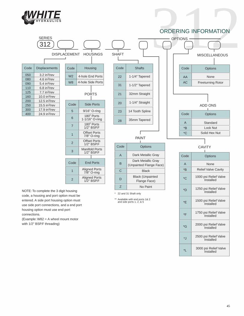
312ORDERING INFORMATION
Housing
4-hole End Ports
4-hole Side Ports
Code
W2
W8
* 22 and 31 Shaft only
** Available with end ports 1& 2 and side ports 1, 2, & 5
Shafts
1-1/4" Tapered
1-1/2" Tapered
32mm Straight
1-1/4" Straight
14 Tooth Spline
35mm Tapered
Code
22
31
21
20
23
28
Code
5
6
7
1
2
3
Side Ports
9/16" O-ring
1800 Ports1-1/16" O-ring
1800 Ports1/2" BSP.F
Offset Ports7/8" O-ring
Offset Ports1/2" BSP.F
Manifold Ports1/2" BSP.F
Code
1
2
End Ports
Aligned Ports7/8" O-ring
Aligned Ports1/2" BSP.F
PORTS
NOTE: To complete the 3 digit housing
code, a housing and port option must be
entered. A side port housing option must
use side port connections, and a end port
housing option must use end port
connections.
(Example: W82 = A wheel mount motor
with 1/2" BSP.F threading)
Code
A
B
C
D
Z
Options
Dark Metallic Gray
Dark Metallic Gray(Unpainted Flange Face)
Black
Black (Unpainted Flange Face)
No Paint
PAINT
CAVITY
ADD ONS
Code
A
*B
*C
Options
Standard
Lock Nut
Solid Hex Nut
MISCELLANEOUS
OPTIONS
Code
AA
AC
Options
None
Freeturning Rotor
Code
A
*B
*C
*D
*E
*F
*G
*J
*L
Options
None
Relief Valve Cavity
1000 psi Relief Valve Installed
1250 psi Relief Valve Installed
1500 psi Relief Valve Installed
1750 psi Relief Valve Installed
2000 psi Relief Valve Installed
2500 psi Relief Valve Installed
3000 psi Relief Valve Installed
Code
050080090110125160200250300400
Displacements
3.2 in3/rev4.6 in3/rev5.4 in3/rev6.8 in3/rev7.7 in3/rev10.0 in3/rev12.5 in3/rev15.5 in3/rev17.9 in3/rev24.9 in3/rev
DISPLACEMENT
312SHAFTHOUSINGS
SERIES

WSSERIES HYDRAULIC MOTORS

2DELIVERING THE POWER TO GET WORK DONE
whitedriveproducts
WS
SPECIFICATIONS
OVERVIEW
Max. Speed Max. Flow Max. Torque Max. Pressure rpm lpm [gpm] Nm [lb-in] bar [psi]
100 100 [6.10] 745 880 76 [20] 95 [25] 280 [2475] 416 [3680] 207 [3000] 310 [4500] 310 [4500]
110 112 [6.85] 675 840 76 [20] 95 [25] 307 [2715] 468 [4145] 207 [3000] 310 [4500] 310 [4500]
130 129 [7.86] 580 730 76 [20] 95 [25] 370 [3275] 550 [4865] 207 [3000] 310 [4500] 310 [4500]
160 162 [9.90] 465 700 76 [20] 114 [30] 462 [4090] 618 [5465] 207 [3000] 276 [4000] 310 [4500]
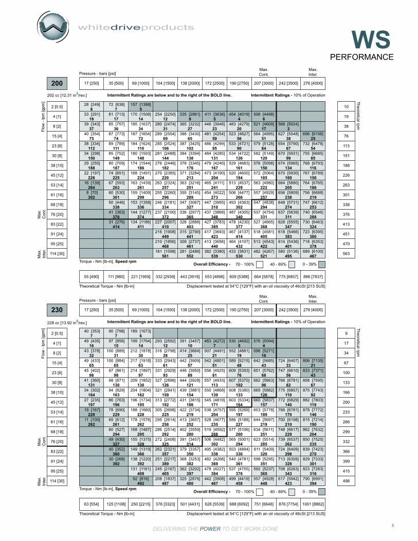
200 202 [12.31] 375 560 76 [20] 114 [30] 576 [5100] 768 [6795] 207 [3000] 276 [4000] 310 [4500]
230 228 [13.92] 325 490 76 [20] 114 [30] 642 [5685] 806 [7135] 207 [3000] 276 [4000] 310 [4500]
320 325 [19.81] 235 350 76 [20] 114 [30] 789 [6980] 1029 [9105] 190 [2750] 224 [3250] 259 [3750]
400 399 [24.36] 190 280 76 [20] 114 [30] 816 [7225] 1034 [9150] 155 [2250] 190 [2750] 224 [3250]
500 496 [30.29] 155 230 76 [20] 114 [30] 824 [7295] 1041 [9210] 121 [1750] 155 [2250] 172 [2500]
CODE Displacement cc [in3/rev] cont. inter. cont. inter. cont. inter. cont. inter. peak
Nine shaft and seven mounting options to meet the most common SAE and European requirements.
Heavy- duty tapered roller bearings for extra side load capacity.
Heavy-duty drive link with larger pitch diameter than competitors for greater resistance to pressure and torque spikes.
Three zone commutator valve for high flow capacity.
Standard case drain with integral internal drain* forextended shaft seal life.*See page 18 for allowable back pressure when utilizing the internal drain.
KEY FEATURES
The WS product family features flow rates up to 76 LPM [20 GPM], torque up to 824 Nm [7,295 lb-in], and pressures up to 207 bar [3000 PSI] at continuous ratings. The WS targets agricultural equipment, skid steer attachments, and other applications that require greater torque under demanding conditions. A distinguishing feature of the WS in relation to competitive products is its heavy duty drive link with a larger pitch diameter. This enables the WS to better withstand pressure and torque spikes and is reflected in its intermittent and peak performance ratings. Additional product features include a three zone commutator valve, heavy-duty tapered roller bearings, and case drain with integral internal drain*. The WS offers displacements from 100cc [6.1in³] to 496cc [30.3in³]. Nine (9) shaft and seven (7) mounting options are available to meet the most common SAE and European requirements.
Intermittent Ratings - 10% of Operation Peak Ratings - 1% of Operation

3DELIVERING THE POWER TO GET WORK DONE
whitedriveproducts
WSPERFORMANCE
11
37
75
151
226
302
378
453
528
604
8
35
74
149
225
300
376
451
527
602
678
754
6
10
71
146
221
297
372
447
522
597
672
747
4
7
68
143
217
292
366
441
515
590
664
739
5
58
137
210
284
357
430
504
578
651
725
801
44
129
200
273
343
415
486
559
632
704
782
850
883
43
119
188
258
326
396
455
527
596
677
758
826
863
42
110
174
240
300
367
433
502
570
652
730
799
835
41
101
162
224
281
345
407
475
541
624
698
768
800
33
87
147
206
261
324
384
447
513
595
668
733
770
[120]
[129]
[138]
[138]
[127]
[109]
[88]
[65]
[39]
[15]
14
15
16
16
14
12
10
7
4
2
[313]
[337]
[354]
[354]
[344]
[326]
[305]
[282]
[254]
[221]
[186]
[144]
35
38
40
40
39
37
34
32
29
25
21
16
[681]
[710]
[781]
[790]
[779]
[765]
[738]
[713]
[686]
[652]
[614]
[573]
77
80
88
89
88
86
83
81
77
74
69
65
[1025]
[1079]
[1205]
[1222]
[1214]
[1200]
[1174]
[1145]
[1116]
[1084]
[1047]
[1009]
116
122
136
138
137
136
133
129
126
122
118
114
[1436]
[1602]
[1654]
[1647]
[1625]
[1601]
[1574]
[1546]
[1513]
[1481]
[1441]
[1379]
162
181
187
186
184
181
178
175
171
167
163
156
[2007]
[2079]
[2071]
[2049]
[2026]
[2002]
[1968]
[1941]
[1910]
[1872]
[1814]
[1762]
[1737]
227
235
234
232
229
226
222
219
216
211
205
199
196
[2364]
[2495]
[2494]
[2474]
[2446]
[2423]
[2351]
[2340]
[2300]
[2278]
[2239]
[2179]
[2176]
267
282
282
280
276
274
266
264
260
257
253
246
246
[2791]
[2871]
[2869]
[2859]
[2810]
[2793]
[2791]
[2760]
[2735]
[2712]
[2653]
[2604]
[2605]
315
324
324
323
318
316
315
312
309
307
300
294
294
[3119]
[3277]
[3279]
[3268]
[3235]
[3220]
[3203]
[3182]
[3152]
[3121]
[3075]
[3037]
[3028]
352
370
371
369
366
364
362
360
356
353
347
343
342
[3386]
[3636]
[3676]
[3682]
[3672]
[3653]
[3637]
[3616]
[3601]
[3568]
[3526]
[3495]
[3472]
383
411
415
416
415
413
411
409
407
403
398
395
392
17 [250] 35 [500] 69 [1000] 104 [1500] 138 [2000] 172 [2500] 207 [3000] 242 [3500] 276 [4000] 310 [4500]
Torque - Nm [lb-in], Speed rpm
Flo
w -
lpm
[gpm
]
Pressure - bars [psi]Max.Inter.
Max.Cont.
27 [243] 55 [485] 110 [971] 165 [1456] 219 [1942] 274 [2427] 329 [2913] 384 [3398] 439 [3883] 494 [4369]
Theoretical Torque - Nm [lb-in]
Max
.In
ter.
Max
.C
ont.
100 cc [6.10 in3/rev.]
100
2 [0.5]
4 [1]
8 [2]
15 [4]
23 [6]
30 [8]
38 [10]
45 [12]
53 [14]
61 [16]
68 [18]
76 [20]
83 [22]
91 [24]
95 [25]
19
38
76
152
228
303
379
455
531
606
682
758
834
909
947
Theoretical rpm
Overall Efficiency - 70 - 100% 40 - 69% 0 - 39%
Intermittent Ratings - 10% of OperationIntermittent Ratings are below and to the right of the BOLD line.
Displacement tested at 54°C [129°F] with an oil viscosity of 46cSt [213 SUS]
9
17
67
135
203
271
339
404
471
8
10
67
135
203
270
338
406
473
541
609
677
6
8
65
133
200
268
335
403
470
538
605
673
742
808
841
4
6
62
130
196
264
331
399
465
532
599
667
735
801
834
5
58
125
190
258
325
391
457
523
589
656
722
787
818
45
118
182
248
313
378
442
508
573
639
699
767
800
40
107
170
234
296
360
403
467
530
594
672
737
771
36
88
143
201
255
313
376
438
502
565
637
702
736
22
71
124
178
232
289
347
406
467
528
598
659
693
9
49
103
155
206
259
316
372
432
492
557
620
648
[106]
[110]
[129]
[134]
[128]
[108]
[80]
[69]
[38]
12
12
15
15
15
12
9
8
4
[334]
[334]
[373]
[378]
[373]
[351]
[322]
[293]
[254]
[210]
[163]
[117]
38
38
42
43
42
40
36
33
29
24
18
13
[757]
[788]
[863]
[863]
[856]
[833]
[803]
[770]
[728]
[687]
[639]
[598]
[596]
[549]
[528]
86
89
98
97
97
94
91
87
82
78
72
68
67
62
60
[1166]
[1213]
[1341]
[1350]
[1337]
[1313]
[1280]
[1247]
[1202]
[1162]
[1116]
[1068]
[1015]
[967]
[939]
132
137
152
152
151
148
145
141
136
131
126
121
115
109
105
[1624]
[1823]
[1838]
[1826]
[1798]
[1761]
[1716]
[1676]
[1635]
[1594]
[1541]
[1500]
[1452]
[1425]
184
206
208
206
203
199
194
189
185
180
174
169
164
161
[2257]
[2314]
[2302]
[2281]
[2236]
[2205]
[2152]
[2114]
[2068]
[2017]
[1960]
[1926]
[1901]
255
261
260
258
253
249
243
239
234
228
221
218
215
[2629]
[2776]
[2770]
[2753]
[2715]
[2684]
[2605]
[2564]
[2534]
[2494]
[2445]
[2403]
[2389]
297
314
313
311
307
303
294
290
286
282
276
272
270
[3015]
[3158]
[3179]
[3177]
[3165]
[3124]
[3108]
[3058]
[3016]
[2977]
[2942]
[2885]
[2861]
341
357
359
359
358
353
351
346
341
336
332
326
323
[3334]
[3558]
[3633]
[3656]
[3652]
[3613]
[3601]
[3553]
[3515]
[3481]
[3436]
[3385]
[3361]
377
402
411
413
413
408
407
402
397
393
388
383
380
[3502]
[3879]
[4054]
[4122]
[4144]
[4133]
[4109]
[4092]
[4051]
[4017]
[3953]
[3906]
[3886]
396
438
458
466
468
467
464
462
458
454
447
441
439
Torque - Nm [lb-in], Speed rpm
Flo
w -
lpm
[gpm
]
17 [250] 35 [500] 69 [1000] 104 [1500] 138 [2000] 172 [2500] 207 [3000] 242 [3500] 276 [4000] 310 [4500]
Pressure - bars [psi]Max.Inter.
Max.Cont.
31 [273] 62 [545] 123 [1090] 185 [1635] 246 [2180] 308 [2726] 370 [3271] 431 [3816] 493 [4361] 554 [4906]
Theoretical Torque - Nm [lb-in]
Max
.In
ter.
Max
.C
ont.
112 cc [6.85 in3/rev.]
110
2 [0.5]
4 [1]
8 [2]
15 [4]
23 [6]
30 [8]
38 [10]
45 [12]
53 [14]
61 [16]
68 [18]
76 [20]
83 [22]
91 [24]
95 [25]
17
34
68
135
203
270
338
405
473
540
608
675
742
810
844
Theoretical rpm
Overall Efficiency - 70 - 100% 40 - 69% 0 - 39%
Intermittent Ratings - 10% of OperationIntermittent Ratings are below and to the right of the BOLD line.
Displacement tested at 54°C [129°F] with an oil viscosity of 46cSt [213 SUS]

4DELIVERING THE POWER TO GET WORK DONE
whitedriveproducts
WS
8
17
58
117
175
234
293
351
410
6
9
57
116
174
233
291
350
408
467
3
6
55
114
172
230
289
347
405
464
522
580
641
701
730
4
52
111
169
227
285
343
401
460
518
575
637
696
726
3
50
107
165
223
280
337
395
453
510
568
627
686
717
3
38
101
158
215
272
329
385
442
499
556
613
672
703
2
35
92
148
202
260
315
361
415
471
526
592
651
683
31
80
132
186
240
289
341
392
448
503
567
625
657
22
68
117
168
220
266
317
367
421
474
536
594
625
9
53
99
147
197
243
289
338
389
441
504
563
589
[114]
[144]
[172]
[182]
[174]
[150]
[120]
[86]
[53]
13
16
19
21
20
17
14
10
6
[367]
[400]
[456]
[469]
[460]
[436]
[403]
[367]
[329]
[289]
41
45
52
53
52
49
46
42
37
33
[830]
[890]
[1022]
[1037]
[1026]
[1004]
[974]
[935]
[891]
[853]
[803]
[753]
[681]
[625]
[601]
94
101
115
117
116
113
110
106
101
96
91
85
77
71
68
[1334]
[1592]
[1609]
[1591]
[1571]
[1537]
[1499]
[1458]
[1415]
[1369]
[1314]
[1242]
[1185]
[1158]
151
180
182
180
178
174
169
165
160
155
148
140
134
131
[1780]
[2081]
[2175]
[2163]
[2143]
[2109]
[2069]
[2027]
[1979]
[1934]
[1879]
[1805]
[1751]
[1722]
201
235
246
244
242
238
234
229
224
219
212
204
198
195
[2264]
[2600]
[2735]
[2730]
[2714]
[2677]
[2633]
[2600]
[2543]
[2498]
[2447]
[2362]
[2307]
[2285]
256
294
309
308
307
303
298
294
287
282
277
267
261
258
[2706]
[3084]
[3265]
[3285]
[3276]
[3246]
[3204]
[3092]
[3048]
[3007]
[2960]
[2938]
[2872]
[2849]
306
348
369
371
370
367
362
349
344
340
335
332
325
322
[3560]
[3749]
[3783]
[3767]
[3741]
[3688]
[3661]
[3620]
[3571]
[3528]
[3510]
[3442]
[3399]
402
424
427
426
423
417
414
409
404
399
397
389
384
[3962]
[4249]
[4330]
[4322]
[4305]
[4264]
[4230]
[4195]
[4147]
[4108]
[4076]
[4011]
[3986]
448
480
489
488
486
482
478
474
469
464
461
453
450
[4219]
[4671]
[4837]
[4866]
[4860]
[4837]
[4818]
[4773]
[4744]
[4714]
[4651]
[4599]
[4594]
477
528
547
550
549
547
544
539
536
533
526
520
519
Torque - Nm [lb-in], Speed rpm
Flo
w -
lpm
[gpm
]
17 [250] 35 [500] 69 [1000] 104 [1500] 138 [2000] 172 [2500] 207 [3000] 242 [3500] 276 [4000] 310 [4500]
Pressure - bars [psi]Max.Inter.
Max.Cont.
35 [313] 71 [625] 141 [1251] 212 [1876] 283 [2502] 353 [3127] 424 [3753] 495 [4378] 565 [5004] 636 [5629]
Theoretical Torque - Nm [lb-in]
Max
.In
ter.
Max
.C
ont.
129 cc [7.86 in3/rev.]
130
2 [0.5]
4 [1]
8 [2]
15 [4]
23 [6]
30 [8]
38 [10]
45 [12]
53 [14]
61 [16]
68 [18]
76 [20]
83 [22]
91 [24]
95 [25]
15
30
59
118
177
236
294
353
412
471
530
588
647
706
735
Theoretical rpm
Overall Efficiency - 70 - 100% 40 - 69% 0 - 39%
Intermittent Ratings - 10% of OperationIntermittent Ratings are below and to the right of the BOLD line.
Displacement tested at 54°C [129°F] with an oil viscosity of 46cSt [213 SUS]
11
23
47
94
141
188
235
282
329
376
10
22
45
94
141
188
234
281
328
375
422
469
516
8
20
43
91
138
186
234
280
327
374
421
467
514
6
18
41
88
135
182
230
276
323
370
417
465
510
558
581
699
5
15
37
84
130
177
224
270
316
363
410
457
503
550
573
691
13
34
79
124
170
217
261
307
353
400
446
491
538
561
679
9
29
71
116
160
206
250
293
338
383
428
476
522
545
661
21
59
100
144
189
234
274
319
363
408
454
500
522
645
16
53
93
135
180
224
264
308
353
396
441
484
511
625
10
45
83
125
168
212
251
295
339
382
427
473
496
609
[173]
[199]
[283]
[278]
[257]
[226]
[188]
[145]
[97]
[44]
20
22
32
31
29
26
21
16
11
5
[485]
[523]
[554]
[609]
[615]
[583]
[547]
[509]
[455]
[402]
[331]
[265]
[193]
55
59
63
69
69
66
62
57
51
45
37
30
22
[1102]
[1194]
[1273]
[1287]
[1265]
[1225]
[1180]
[1192]
[1178]
[1110]
[1048]
[980]
[913]
125
135
144
145
143
138
133
135
133
125
118
111
103
[1679]
[1831]
[1974]
[2014]
[1990]
[1958]
[1914]
[1861]
[1817]
[1761]
[1697]
[1616]
[1557]
[1553]
[1443]
[1222]
190
207
223
228
225
221
216
210
205
199
192
183
176
175
163
138
[2258]
[2425]
[2635]
[2728]
[2711]
[2678]
[2633]
[2581]
[2530]
[2474]
[2408]
[2337]
[2264]
[2180]
[2134]
[1917]
255
274
298
308
306
303
298
292
286
280
272
264
256
246
241
217
[2989]
[3255]
[3416]
[3412]
[3387]
[3353]
[3289]
[3231]
[3173]
[3104]
[3036]
[2965]
[2890]
[2843]
[2618]
338
368
388
386
383
379
372
365
359
351
343
335
327
321
296
[3511]
[3830]
[4071]
[4108]
[4088]
[4055]
[4000]
[3905]
[3857]
[3779]
[3712]
[3658]
[3587]
[3543]
[3324]
397
433
460
464
462
458
452
441
436
427
419
413
405
400
376
[4251]
[4654]
[4737]
[4761]
[4730]
[4688]
[4627]
[4572]
[4498]
[4424]
[4358]
[4286]
[4253]
[4034]
480
526
535
538
534
530
523
517
508
500
492
484
481
456
[4459]
[4931]
[5074]
[5116]
[5085]
[5046]
[4986]
[4934]
[4853]
[4777]
[4721]
[4639]
[4611]
[4383]
504
557
573
578
575
570
563
557
548
540
533
524
521
495
[4664]
[5163]
[5370]
[5463]
[5451]
[5423]
[5363]
[5301]
[5240]
[5167]
[5093]
[5027]
[4968]
[4729]
527
583
607
617
616
613
606
599
592
584
575
568
561
534
Torque - Nm [lb-in], Speed rpm
Flo
w -
lpm
[gpm
]
17 [250] 35 [500] 69 [1000] 104 [1500] 138 [2000] 172 [2500] 207 [3000] 242 [3500] 259 [3750] 276 [4000]
Pressure - bars [psi]Max.Inter.
Max.Cont.
45 [394] 89 [788] 178 [1576] 267 [2363] 356 [3151] 445 [3939] 534 [4727] 623 [5515] 668 [5909] 712 [6303]
Theoretical Torque - Nm [lb-in]
Max
.In
ter.
Max
.C
ont.
162 cc [9.90 in3/rev.]
160
2 [0.5]
4 [1]
8 [2]
15 [4]
23 [6]
30 [8]
38 [10]
45 [12]
53 [14]
61 [16]
68 [18]
76 [20]
83 [22]
91 [24]
95 [25]
114 [30]
12
24
47
94
140
187
234
280
327
374
420
467
514
560
584
700
Theoretical rpm
Overall Efficiency - 70 - 100% 40 - 69% 0 - 39%
Intermittent Ratings - 10% of OperationIntermittent Ratings are below and to the right of the BOLD line.
Displacement tested at 54°C [129°F] with an oil viscosity of 46cSt [213 SUS]
PERFORMANCE
5DELIVERING THE POWER TO GET WORK DONE
whitedriveproducts
WSPERFORMANCE
8
18
37
75
112
150
188
226
264
302
7
17
36
74
111
149
187
225
263
301
338
376
414
5
14
34
72
110
148
186
224
261
299
336
374
411
12
31
69
106
144
182
220
257
296
334
372
410
449
468
561
9
27
65
102
138
176
213
251
289
327
365
403
441
461
552
5
23
59
95
131
167
204
241
273
310
348
385
423
440
539
4
20
56
90
126
161
194
229
266
302
340
377
414
432
530
6
17
51
84
120
150
185
222
257
294
331
368
405
422
521
3
38
67
99
134
169
205
238
274
311
347
383
401
495
25
54
85
116
150
186
219
253
288
324
360
378
467
[249]
[291]
[343]
[354]
[334]
[298]
[255]
[197]
[139]
[70]
28
33
39
40
38
34
29
22
16
8
[638]
[713]
[757]
[773]
[789]
[752]
[709]
[651]
[593]
[530]
[446]
[363]
[276]
72
81
85
87
89
85
80
74
67
60
50
41
31
[1388]
[1508]
[1637]
[1654]
[1624]
[1593]
[1544]
[1491]
[1439]
[1409]
[1358]
[1277]
[1186]
157
170
185
187
184
180
174
168
163
159
153
144
134
[2250]
[2474]
[2554]
[2524]
[2488]
[2446]
[2385]
[2324]
[2260]
[2181]
[2100]
[2007]
[1908]
[1856]
[1598]
254
280
289
285
281
276
270
263
255
246
237
227
216
210
181
[2961]
[3232]
[3430]
[3425]
[3394]
[3345]
[3284]
[3216]
[3145]
[3067]
[2977]
[2888]
[2790]
[2737]
[2486]
335
365
388
387
384
378
371
363
355
347
336
326
315
309
281
[3636]
[3948]
[4254]
[4299]
[4285]
[4240]
[4190]
[4111]
[4022]
[3955]
[3868]
[3783]
[3693]
[3656]
[3380]
411
446
481
486
484
479
473
465
454
447
437
427
417
413
382
[4019]
[4279]
[4627]
[4721]
[4722]
[4683]
[4600]
[4537]
[4477]
[4363]
[4305]
[4230]
[4137]
[4107]
[3831]
454
483
523
533
534
529
520
513
506
493
487
478
467
464
433
[4498]
[4609]
[4995]
[5128]
[5149]
[5098]
[5064]
[4980]
[4929]
[4838]
[4754]
[4665]
[4581]
[4543]
[4267]
508
521
564
579
582
576
572
563
557
547
537
527
518
513
482
[5024]
[5548]
[5790]
[5931]
[5965]
[5930]
[5880]
[5809]
[5731]
[5639]
[5555]
[5466]
[5436]
[5136]
568
627
654
670
674
670
664
656
648
637
628
618
614
580
[6156]
[6478]
[6685]
[6793]
[6789]
[6765]
[6688]
[6612]
[6546]
[6463]
[6395]
[6353]
[6100]
696
732
755
768
767
764
756
747
740
730
723
718
689
Torque - Nm [lb-in], Speed rpm
Flo
w -
lpm
[gpm
]
17 [250] 35 [500] 69 [1000] 104 [1500] 138 [2000] 172 [2500] 190 [2750] 207 [3000] 242 [3500] 276 [4000]
Pressure - bars [psi]Max.Inter.
Max.Cont.
55 [490] 111 [980] 221 [1959] 332 [2939] 443 [3918] 553 [4898] 609 [5388] 664 [5878] 775 [6857] 886 [7837]
Theoretical Torque - Nm [lb-in]
Max
.In
ter.
Max
.C
ont.
202 cc [12.31 in3/rev.]
200
2 [0.5]
4 [1]
8 [2]
15 [4]
23 [6]
30 [8]
38 [10]
45 [12]
53 [14]
61 [16]
68 [18]
76 [20]
83 [22]
91 [24]
95 [25]
114 [30]
10
19
38
76
113
151
188
226
263
301
338
376
413
451
470
563
Theoretical rpm
Overall Efficiency - 70 - 100% 40 - 69% 0 - 39%
Intermittent Ratings - 10% of OperationIntermittent Ratings are below and to the right of the BOLD line.
Displacement tested at 54°C [129°F] with an oil viscosity of 46cSt [213 SUS]
Overall Efficiency - 70 - 100% 40 - 69% 0 - 39%
Intermittent Ratings - 10% of OperationIntermittent Ratings are below and to the right of the BOLD line.
Displacement tested at 54°C [129°F] with an oil viscosity of 46cSt [213 SUS]
7
16
32
65
98
131
164
197
229
262
7
15
31
65
98
130
163
196
229
261
294
327
360
392
6
14
30
63
97
130
162
195
228
262
295
328
360
392
408
492
12
28
61
93
126
159
192
225
258
292
325
357
389
405
487
10
25
57
89
121
154
186
219
252
280
314
350
382
397
480
7
21
51
81
113
139
171
204
235
268
302
338
369
384
467
5
19
48
76
102
133
164
197
227
260
294
330
361
376
458
4
16
43
68
96
126
157
189
219
251
285
320
351
365
448
33
56
82
110
140
170
210
229
262
298
328
343
423
21
43
67
92
119
146
190
204
235
270
301
316
394
[353]
[435]
[378]
[433]
[402]
[360]
[302]
[235]
[167]
[100]
40
49
43
49
45
41
34
27
19
11
[798]
[856]
[889]
[884]
[861]
[871]
[829]
[763]
[690]
[612]
[527]
[430]
[352]
[268]
90
97
100
100
97
98
94
86
78
69
60
49
40
30
[1673]
[1764]
[1878]
[1918]
[1897]
[1852]
[1804]
[1734]
[1660]
[1576]
[1487]
[1375]
[1319]
[1220]
[1161]
[816]
189
199
212
217
214
209
204
196
188
178
168
155
149
138
131
92
[2592]
[2798]
[2943]
[2929]
[2896]
[2841]
[2772]
[2698]
[2614]
[2514]
[2408]
[2321]
[2217]
[2167]
[1837]
293
316
333
331
327
321
313
305
295
286
272
262
251
245
208
[3457]
[3664]
[3909]
[3950]
[3928]
[3881]
[3815]
[3734]
[3657]
[3559]
[3457]
[3357]
[3253]
[3202]
[2876]
391
414
442
446
444
439
431
422
413
402
391
379
368
362
325
[4272]
[4491]
[4801]
[4925]
[4933]
[4868]
[4819]
[4757]
[4677]
[4592]
[4482]
[4382]
[4268]
[4227]
[3908]
483
507
542
556
557
550
545
538
528
519
506
495
482
478
442
[4692]
[4881]
[5215]
[5393]
[5370]
[5380]
[5334]
[5269]
[5188]
[5106]
[5001]
[4894]
[4781]
[4755]
[4419]
530
552
589
609
607
608
603
595
586
577
565
553
540
537
499
[5094]
[5271]
[5685]
[5762]
[5863]
[5882]
[5837]
[5778]
[5697]
[5611]
[5514]
[5409]
[5295]
[5237]
[4928]
576
596
642
651
662
665
660
653
644
634
623
611
598
592
557
[6407]
[6610]
[6781]
[6857]
[6829]
[6781]
[6198]
[6617]
[6537]
[6409]
[6309]
[6263]
[5942]
724
747
766
775
772
766
700
748
739
724
713
708
617
[7135]
[7371]
[7595]
[7743]
[7803]
[7772]
[7214]
[7632]
[7525]
[7423]
[7333]
[7283]
[6991]
806
833
858
875
882
878
815
862
850
839
829
823
790
17 [250] 35 [500] 69 [1000] 104 [1500] 138 [2000] 172 [2500] 190 [2750] 207 [3000] 242 [3500] 276 [4000]
Torque - Nm [lb-in], Speed rpm
Flo
w -
lpm
[gpm
]
Pressure - bars [psi]Max.Inter.
Max.Cont.
63 [554] 125 [1108] 250 [2215] 376 [3323] 501 [4431] 626 [5539] 688 [6092] 751 [6646] 876 [7754] 1001 [8862]
Theoretical Torque - Nm [lb-in]
Max
.In
ter.
Max
.C
ont.
228 cc [13.92 in3/rev.]
230
2 [0.5]
4 [1]
8 [2]
15 [4]
23 [6]
30 [8]
38 [10]
45 [12]
53 [14]
61 [16]
68 [18]
76 [20]
83 [22]
91 [24]
95 [25]
114 [30]
9
17
34
67
100
133
166
200
233
266
299
332
366
399
415
498
Theoretical rpm

6DELIVERING THE POWER TO GET WORK DONE
whitedriveproducts
WS
5
11
22
46
70
93
117
141
164
188
211
235
4
10
22
46
69
93
117
141
164
187
211
234
258
282
293
3
9
20
44
67
91
114
138
161
185
209
233
255
279
290
350
1
7
18
41
64
87
110
134
157
181
204
227
249
273
285
344
6
16
36
57
80
103
125
146
169
192
216
240
264
276
335
4
14
33
52
75
94
116
139
163
185
210
234
258
270
329
3
12
30
48
65
87
109
132
155
178
202
227
251
261
322
1
11
26
42
59
80
103
124
149
174
197
222
246
257
318
9
20
37
53
74
96
116
19
32
49
68
89
109
[571]
[595]
[597]
[565]
[677]
[641]
[566]
[473]
[262]
[161]
[160]
[25]
65
67
67
64
77
72
64
53
30
18
18
3
[1196]
[1291]
[1328]
[1299]
[1367]
[1299]
[1217]
[1155]
[1076]
[994]
[997]
[863]
[747]
[667]
[616]
135
146
150
147
154
147
137
131
122
112
113
97
84
75
70
[2406]
[2568]
[2751]
[2761]
[2834]
[2766]
[2683]
[2587]
[2483]
[2359]
[2344]
[2198]
[2091]
[1900]
[1828]
[1353]
272
290
311
312
320
313
303
292
281
267
265
248
236
215
207
153
[3524]
[3764]
[4083]
[4197]
[4283]
[4221]
[4142]
[4049]
[3943]
[3818]
[3805]
[3673]
[3540]
[3365]
[3272]
[2789]
398
425
461
474
484
477
468
458
446
431
430
415
400
380
370
315
[4937]
[5277]
[5547]
[5679]
[5640]
[5568]
[5479]
[5367]
[5253]
[5244]
[5114]
[4973]
[4804]
[4716]
[4230]
558
596
627
642
637
629
619
606
594
593
578
562
543
533
478
[5514]
[5834]
[6173]
[6347]
[6329]
[6241]
[6151]
[6078]
[5966]
[5953]
[5821]
[5676]
[5510]
[5423]
[4943]
623
659
698
717
715
705
695
687
674
673
658
641
623
613
559
[6101]
[6396]
[6747]
[7004]
[6959]
[6935]
[6850]
[6764]
[6660]
[6649]
[6515]
[6368]
[6202]
[6175]
[5653]
689
723
762
791
786
784
774
764
753
751
736
720
701
698
639
[6599]
[6977]
[7261]
[7548]
[7617]
[7603]
[7523]
[7434]
[7290]
[7178]
[7052]
[6913]
[6756]
[6711]
[6233]
746
788
821
853
861
859
850
840
824
811
797
781
763
758
704
[7510]
[7785]
[8116]
[8236]
[8265]
[8197]
[8099]
849
880
917
937
934
926
915
[8337]
[8646]
[8816]
[8895]
[8861]
[8761]
942
977
996
1005
1001
990
17 [250] 35 [500] 69 [1000] 104 [1500] 138 [2000] 155 [2250] 172 [2500] 190 [2750] 207 [3000] 224 [3250]
Torque - Nm [lb-in], Speed rpm
Flo
w -
lpm
[gpm
]
Pressure - bars [psi]Max.Inter.
Max.Cont.
89 [788] 178 [1576] 356 [3153] 534 [4729] 713 [6306] 802 [7094] 891 [7882] 980 [8670] 1069 [9459] 1158 [10247]
Theoretical Torque - Nm [lb-in]
Max
.In
ter.
Max
.C
ont.
325 cc [19.81 in3/rev.]
320
2 [0.5]
4 [1]
8 [2]
15 [4]
23 [6]
30 [8]
38 [10]
45 [12]
53 [14]
61 [16]
68 [18]
76 [20]
83 [22]
91 [24]
95 [25]
114 [30]
6
12
24
47
70
94
117
140
164
187
210
234
257
280
292
350
Theoretical rpm
Overall Efficiency - 70 - 100% 40 - 69% 0 - 39%
Intermittent Ratings - 10% of OperationIntermittent Ratings are below and to the right of the BOLD line.
Displacement tested at 54°C [129°F] with an oil viscosity of 46cSt [213 SUS]
4
9
18
38
57
76
4
8
18
37
56
75
95
114
133
151
2
7
16
35
54
73
93
112
131
150
169
189
207
226
246
284
6
15
34
52
72
91
110
129
148
167
187
205
224
244
282
5
13
31
50
69
88
107
126
145
165
184
202
221
241
279
4
11
27
46
65
82
101
119
138
158
177
198
217
236
275
3
10
23
40
57
76
95
112
131
151
171
192
211
231
269
2
7
17
33
50
69
88
102
123
143
163
184
204
224
263
12
27
43
61
80
97
114
134
154
175
195
215
254
24
36
52
71
88
104
122
143
165
184
205
245
[717]
[752]
[762]
[724]
[663]
[585]
81
85
86
82
75
66
[1534]
[1605]
[1654]
[1635]
[1573]
[1490]
[1365]
[1237]
[1104]
[934]
173
181
187
185
178
168
154
140
125
106
[3148]
[3263]
[3422]
[3460]
[3393]
[3306]
[3197]
[3066]
[2924]
[2755]
[2578]
[2379]
[2174]
[2000]
[1739]
[1162]
356
369
387
391
383
374
361
346
330
311
291
269
246
226
197
131
[4074]
[4274]
[4361]
[4301]
[4216]
[4110]
[3978]
[3838]
[3672]
[3493]
[3286]
[3076]
[2850]
[2600]
[2100]
460
483
493
486
476
464
450
434
415
395
371
348
322
294
237
[4865]
[5090]
5240]
[5201]
[5119]
[5015]
[4880]
[4745]
[4580]
[4405]
[4205]
[3987]
[3756]
[3515]
[2991]
550
575
592
588
578
567
551
536
518
498
475
451
424
397
338
[5648]
[5861]
[6086]
[6074]
[6007]
[5880]
[5744]
[5609]
[5456]
[5279]
[5084]
[4911]
[4668]
[4421]
[3901]
638
662
688
686
679
664
649
634
617
597
575
555
528
500
441
[6404]
[6613]
[6871]
[6926]
[6868]
[6764]
[6638]
[6504]
[6357]
[6185]
[5997]
[5789]
[5571]
[5323]
[4798]
724
747
776
783
776
764
750
735
718
699
678
654
629
602
542
[7222]
[7310]
[7667]
[7750]
[7716]
[7626]
[7503]
[7369]
[7228]
[7065]
[6879]
[6671]
[6446]
[6214]
[5687]
816
826
866
876
872
862
848
833
817
798
777
754
728
702
643
[8337]
[8524]
[8545]
[8463]
[8361]
[8217]
[8079]
[7931]
[7754]
[7543]
[7332]
[7093]
[6574]
942
963
966
956
945
929
913
896
876
852
828
801
743
[9345]
[9341]
[9289]
[9195]
[9058]
[8913]
[8774]
[8606]
[8413]
[8197]
[7963]
[7458]
1056
1055
1050
1039
1024
1007
991
972
951
926
900
843
17 [250] 35 [500] 69 [1000] 86 [1250] 104 [1500] 121 [1750] 138 [2000] 155 [2250] 172 [2500] 190 [2750]
Torque - Nm [lb-in], Speed rpm
Flo
w -
lpm
[gpm
]
Pressure - bars [psi]Max.Inter.
Max.Cont.
110 [969] 219 [1939] 438 [3877] 548 [4846] 657 [5816] 767 [6785] 876 [7754] 986 [8723] 1095 [9693] 1205 [10662]
Theoretical Torque - Nm [lb-in]
Max
.In
ter.
Max
.C
ont.
399 cc [24.36 in3/rev.]
400
2 [0.5]
4 [1]
8 [2]
15 [4]
23 [6]
30 [8]
38 [10]
45 [12]
53 [14]
61 [16]
68 [18]
76 [20]
83 [22]
91 [24]
99 [26]
114 [30]
5
10
19
38
57
76
95
114
133
152
171
190
209
228
247
285
Theoretical rpm
Overall Efficiency - 70 - 100% 40 - 69% 0 - 39%
Intermittent Ratings - 10% of OperationIntermittent Ratings are below and to the right of the BOLD line.
Displacement tested at 54°C [129°F] with an oil viscosity of 46cSt [213 SUS]
PERFORMANCE

7DELIVERING THE POWER TO GET WORK DONE
whitedriveproducts
WS
3
7
15
31
46
62
77
3
7
15
30
46
61
77
92
108
123
139
154
169
3
7
14
30
45
61
76
92
107
122
138
153
169
184
200
3
6
14
29
44
60
75
91
106
121
137
152
168
184
199
230
6
13
28
43
58
74
89
104
120
135
151
167
182
198
229
5
11
25
41
56
71
86
101
116
132
147
164
179
196
227
4
9
21
36
50
66
82
96
111
127
143
161
175
193
224
7
16
28
43
59
75
89
104
120
136
155
170
188
219
13
22
34
50
68
80
95
111
127
148
162
181
213
[832]
[868]
[882]
[843]
[783]
[696]
[600]
94
98
100
95
89
79
68
[1861]
[1743]
[1812]
[1803]
[1737]
[1639]
[1523]
[1568]
[1389]
[1219]
[1004]
[849]
[688]
210
197
205
204
196
185
172
177
157
138
114
96
78
[2859]
[2781]
[2905]
[2938]
[2869]
[2778]
[2652]
[2318]
[2533]
[2347]
[2147]
[1919]
[1360]
[1416]
[1138]
323
314
328
332
324
314
300
262
286
265
243
217
154
160
129
[3853]
[3802]
[3959]
[4070]
[4009]
[3918]
[3800]
[3624]
[3673]
[3486]
[3277]
[3047]
[2439]
[2371]
[2048]
[1647]
435
430
447
460
453
443
429
410
415
394
370
344
276
268
231
186
[4797]
[5001]
[5170]
[5133]
[5047]
[4929]
[4593]
[4810]
[4630]
[4424]
[4190]
[3595]
[3512]
[2844]
[2581]
542
565
584
580
570
557
519
544
523
500
473
406
397
321
292
[5766]
[5990]
[6225]
[6237]
[6161]
[6052]
[5696]
[5918]
[5740]
[5536]
[5311]
[4724]
[4633]
[3988]
[3387]
652
677
703
705
696
684
644
669
649
626
600
534
524
451
383
[6876]
[6900]
[7212]
[7296]
[7205]
[7123]
[6811]
[7027]
[6861]
[6659]
[6446]
[5839]
[5755]
[5097]
[4494]
777
780
815
824
814
805
770
794
775
752
728
660
650
576
508
[7779]
[8118]
[8234]
[8231]
[8175]
[7885]
[8092]
[7936]
[7753]
[7537]
[6938]
[6863]
[6218]
[5631]
879
917
930
930
924
891
914
897
876
852
784
776
703
636
[8956]
[9141]
[9210]
[9175]
[8916]
[9122]
[8968]
[8806]
[8606]
[8028]
[7950]
[7320]
[6738]
1012
1033
1041
1037
1008
1031
1013
995
972
907
898
827
761
17 [250] 35 [500] 52 [750] 69 [1000] 86 [1250] 104 [1500] 121 [1750] 138 [2000] 155 [2250]
Torque - Nm [lb-in], Speed rpm
Flo
w -
lpm
[gpm
]
Pressure - bars [psi]Max.Inter.
Max.Cont.
136 [1205] 272 [2410] 409 [3616] 545 [4821] 681 [6026] 817 [7231] 953 [8436] 1090 [9642] 1226 [10847]
Theoretical Torque - Nm [lb-in]
Max
.In
ter.
Max
.C
ont.
496 cc [30.29 in3/rev.]
500
2 [0.5]
4 [1]
8 [2]
15 [4]
23 [6]
30 [8]
38 [10]
45 [12]
53 [14]
61 [16]
68 [18]
76 [20]
83 [22]
91 [24]
99 [26]
114 [30]
4
8
16
31
46
62
77
92
107
123
138
153
168
184
199
229
Theoretical rpm
Intermittent Ratings - 10% of OperationIntermittent Ratings are below and to the right of the BOLD line.
Overall Efficiency - 70 - 100% 40 - 69% 0 - 39%
Displacement tested at 54°C [129°F] with an oil viscosity of 46cSt [213 SUS]
PERFORMANCE

8DELIVERING THE POWER TO GET WORK DONE
whitedriveproducts
WS131 [5.16] Max.
106,4 [4.188]
13,8 [.545]13,3 [.525]
21 [.84]
19 [.73]18 [.71]
6 [.25]
82,6 [3.250]82,4 [3.245]
22 [.87]22 [.85]
D
109 [4.28] Max.
13,8 [.545]13,3 [.525]
106,4 [4.188]
6 [.25] 20 [.79] Max.
.70
82,6 [3.250]82,4 [3.245]
D
22 [.87]22 [.85]
D
21 [.84]
22 [.87]22 [.85]
3 [.11]
17 [.70]
82,6 [3.250]82,4 [3.245]
13,8 [.545]13,3 [.525]106,4 [4.188]
136 [5.34] Max.
45°
355 & 356 SERIES HOUSINGS
A0 2-Hole SAE A Mount with End Ports A7 2-Hole SAE A Mount with Side Ports
A2 4-Hole Magneto with End Ports A8 4-Hole Magneto with Side Ports
AG 4-Hole Square SAE A Mount with End Ports AH 4-Hole Square SAE A Mount with Side Ports
NOTE: Overall motor length varies depending on the displacement. Dimension D is found on page 10.

9DELIVERING THE POWER TO GET WORK DONE
whitedriveproducts
WS355 & 356 SERIES HOUSINGS
W2 W8
Y2 4-Hole 4.25” Pilot Wheel Mount with End Ports Y8 4-Hole 4.25” Wheel Mount with Side Ports
Z2 4-Hole Euro Wheel Mount with End Ports Z8 4-Hole Euro Wheel Mount with Side Ports
4-Hole 3.25” Pilot Wheel Mount with End Ports 4-Hole 3.25” Wheel Mount with Side Ports
134 [5.28] Max.
7 [.26]6 [.24]
93 [3.65]
108,0 [4.250]107,8 [4.245]
47 [1.86]46 [1.80]
4 [.15]3 [.11]
127,0 [5.000]126,9 [4.995]
19 [.75]
F
147,6 [5.812]
13,8 [.545]13,3 [.525]
140 [5.43] Max.
45°
82,6 [3.250]82,5 [3.247]
5,7 [.225] 36 [1.42]
41 [1.62]
6,4 [.25]
E
127,0 [4.999]126,8 [4.994]
147,6 [5.812]
13,3 [.522]13,1 [.514]
73 [2.87]125.0 [4.921]124.9 [4.919]
8 [.33]8 [.30]
16 [.63]43,6 [1.716]43,0 [1.696]
G
139 [5.47] Max.
160,4 [6.315]159,6 [6.283]
13,5 [.531]
NOTE: Overall motor length varies depending on the displacement.Dimension E is found on page 10.
NOTE: Overall motor length varies depending on the displacement.Dimension F is found on page 11.
NOTE: Overall motor length varies depending on the displacement.Dimension G is found on page 11.

10DELIVERING THE POWER TO GET WORK DONE
whitedriveproducts
WS355 & 356 SERIES TECHNICAL INFORMATION
LENGTH / WEIGHT CHARTSAE A Mount - Dimension D
Code mm [in] kg [lb] 100 193 [7.60] 10,8 [23.8] 110 196 [7.70] 11,0 [24.1] 130 199 [7.83] 11,1 [24.5] 160 205 [8.08] 11,5 [25.4] 200 213 [8.38] 11,9 [26.2] 230 219 [8.62] 12,3 [27.1] 320 237 [9.33] 13,3 [29.2] 400 237 [9.33] 13,3 [29.2] 500 252 [9.93] 14,0 [30.9]
LENGTH / WEIGHT CHART3.25” Wheel Mount - Dimension E
Code mm [in] kg [lb] 100 158 [6.23] 12,5 [27.5] 110 161 [6.33] 12,6 [27.8] 130 164 [6.46] 12,8 [28.2] 160 170 [6.71] 13,3 [29.2] 200 178 [7.01] 13,6 [29.9] 230 184 [7.25] 14,0 [30.8] 320 202 [7.96] 15,0 [32.9] 400 202 [7.96] 15,0 [32.9] 500 217 [8.56] 15,8 [34.7]
NOTE:WS motor weights vary ± 0,5 kg [1 lbs] depending upon motor configuration. Add 3,8 mm [.15 in] to dimension D for Magneto mount.
NOTE:WS motor weights vary ± 0,5 kg [1 lbs] depending upon motor configuration.
SAE “A” MOUNT
9,000
8,000
7,000
6,000
5,000
4,000
3,000
2,000
1,000lb
-4 -3 -2 -1 0 1 2 3 4 in
-100 -75 -50 -25 0 25 50 75 100 mm
Bearing
Shaft
445 daN [1000 lbs]
445 daN [1000 lbs]
4,000
3,500
3,000
2,500
2,000
1,500
1,000
500daN
3.25” PILOT WHEEL MOUNT
9,000
8,000
7,000
6,000
5,000
4,000
3,000
2,000
1,000lb
-4 -3 -2 -1 0 1 2 3 4 in
-100 -75 -50 -25 0 25 50 75 100 mm
Bearing
Shaft
445 daN [1000 lbs]
445 daN [1000 lbs]
4,000
3,500
3,000
2,500
2,000
1,500
1,000
500daN
BEARING LOADMultiplication Factor Table
RPM Factor 050 1.23 100 1.00 200 0.81 300 0.72 400 0.66 500 0.62 600 0.58 700 0.56 800 0.50
Bearing Curve: The bearing curve represents allowable bearing loads for a B10 life of 2,000 hours at 100 rpm. The curve includes affects of 1,000 lbs inward/outward net thrust* (see note on page 11). Radial loads for speeds other than 100 rpm may be calculated using the multiplication factor table located below.
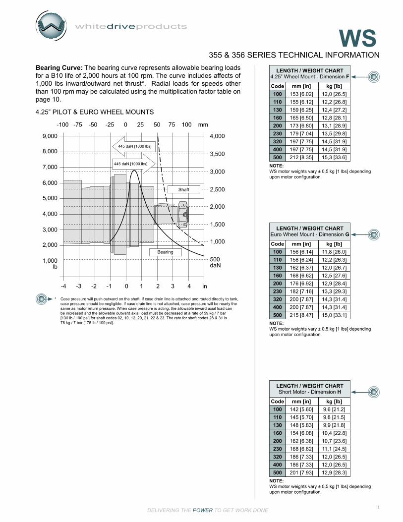
11DELIVERING THE POWER TO GET WORK DONE
whitedriveproducts
WS355 & 356 SERIES TECHNICAL INFORMATION
4.25” PILOT & EURO WHEEL MOUNTS
9,000
8,000
7,000
6,000
5,000
4,000
3,000
2,000
1,000lb
-4 -3 -2 -1 0 1 2 3 4 in
-100 -75 -50 -25 0 25 50 75 100 mm
Bearing
Shaft
445 daN [1000 lbs]
445 daN [1000 lbs]
4,000
3,500
3,000
2,500
2,000
1,500
1,000
500daN
LENGTH / WEIGHT CHART4.25” Wheel Mount - Dimension F
Code mm [in] kg [lb] 100 153 [6.02] 12,0 [26.5] 110 155 [6.12] 12,2 [26.8] 130 159 [6.25] 12,4 [27.2] 160 165 [6.50] 12,8 [28.1] 200 173 [6.80] 13,1 [28.9] 230 179 [7.04] 13,5 [29.8] 320 197 [7.75] 14,5 [31.9] 400 197 [7.75] 14,5 [31.9] 500 212 [8.35] 15,3 [33.6]
LENGTH / WEIGHT CHARTEuro Wheel Mount - Dimension G
Code mm [in] kg [lb] 100 156 [6.14] 11,8 [26.0] 110 158 [6.24] 12,2 [26.3] 130 162 [6.37] 12,0 [26.7] 160 168 [6.62] 12,5 [27.6] 200 176 [6.92] 12,9 [28.4] 230 182 [7.16] 13,3 [29.3] 320 200 [7.87] 14,3 [31.4] 400 200 [7.87] 14,3 [31.4] 500 215 [8.47] 15,0 [33.1]
NOTE:WS motor weights vary ± 0,5 kg [1 lbs] depending upon motor configuration.
NOTE:WS motor weights vary ± 0,5 kg [1 lbs] depending upon motor configuration.
LENGTH / WEIGHT CHARTShort Motor - Dimension H
Code mm [in] kg [lb] 100 142 [5.60] 9,6 [21.2] 110 145 [5.70] 9,8 [21.5] 130 148 [5.83] 9,9 [21.8] 160 154 [6.08] 10,4 [22.8] 200 162 [6.38] 10,7 [23.6] 230 168 [6.62] 11,1 [24.5] 320 186 [7.33] 12,0 [26.5] 400 186 [7.33] 12,0 [26.5] 500 201 [7.93] 12,9 [28.3]NOTE:WS motor weights vary ± 0,5 kg [1 lbs] depending upon motor configuration.
* Case pressure will push outward on the shaft. If case drain line is attached and routed directly to tank, case pressure should be negligible. If case drain line is not attached, case pressure will be nearly the same as motor return pressure. When case pressure is acting, the allowable inward axial load can be increased and the allowable outward axial load must be decreased at a rate of 59 kg / 7 bar [130 lb / 100 psi] for shaft codes 02, 10, 12, 20, 21, 22 & 23. The rate for shaft codes 28 & 31 is 78 kg / 7 bar [175 lb / 100 psi].
Bearing Curve: The bearing curve represents allowable bearing loads for a B10 life of 2,000 hours at 100 rpm. The curve includes affects of 1,000 lbs inward/outward net thrust*. Radial loads for speeds other than 100 rpm may be calculated using the multiplication factor table on page 10.

12DELIVERING THE POWER TO GET WORK DONE
whitedriveproducts
WS355 & 356 SERIES SHAFTS
J
25,4 [1.000]25,3 [.998]
28,2 [1.113] Max.
38 [1.51]
25,7 [1.010]25,1 [.990]6 [.24]
6,4 [.251]6,4 [.250]
MountingFlange Mounting
Flange
1/4-20 UNC20 [.80] Deep Min.
8,0 [.314]8,0 [.313]
J
47 [1.86] Max.33 [1.28]31 [1.22]
35,3 [1.391]35,1 [1.380]
31,8 [1.250]31,7 [1.248]
MountingFlange
3/8-16 UNC25 [1.00] Deep Min.
J
25,4 [.999]25,3 [.995]
23 [.90] Min. Spline
31 [1.21] Max.
6-B Spline (SAE J499 Standard)
1/4-20 UNC20 [.80] Deep Min.
26 [1.03]26 [1.02]
J
45 [1.79] Max.
31,7 [1.249]31,6 [1.245]
14 Tooth 12/24 pitch Std. (ANSI B92.1-1996 Spline)
MountingFlange
3/8-16 UNC25 [1.00] Deep Min.
33 [1.30] Min. Spline
28,0 [1.102]27,7 [1.089]
7 [.29]5 [.21]
33 [1.28]31 [1.22]
38 [1.50] Max
25,0 [.984]25,0 [.983]
M8 x 1.25 - 6H23 [.90] Deep Min.
8,0 [.315]8,0 [.314]
MountingFlangeJ
10 1” Straight
Max. Torque: 661 Nm [5,850 lb-in] Max. Torque: 429 Nm [3,800 lb-in]
23 14 Tooth Spline
Max. Torque: 881 Nm [7,800 lb-in]
02 6-B Spline
12 25mm Straight
Max. Torque: 631 Nm [5,580 lb-in]
20 1-1/4” Straight
Max. Torque: 881 Nm [7,800 lb-in]MOUNTING FLANGE TO SHAFT END - Dimension J
A0, A7, A2 & A8 W2 & W8 Y2 & Y8 Z2 & Z8 AG, & AH
02 51 [2.00] 47 [1.85] 85 [3.34] 91 [3.58] 88 [3.45]
10 51 [2.00] 47 [1.85] 85 [3.34] 91 [3.58] 88 [3.45]
12 51 [2.00] 56 [1.86] 85 [3.34] 91 [3.58] 88 [3.46]
20 55 [2.18] 52 [2.03] 89 [3.52] 96 [3.76] 92 [3.63]
21 65 [2.54] 61 [2.39] 99 [3.88] 105 [4.12] 101 [3.99]
22 64 [2.51] 60 [2.36] 103 [4.04] 104 [4.09] 101 [3.96]
23 55 [2.17] 52 [2.03] 89 [3.51] 95 [3.75] 92 [3.63]
28 N/A N/A 102 [4.02] 107 [4.20] 104 [4.08]
31 N/A N/A 117 [4.62] 123 [4.86] 120 [4.73]
Code
NOTE: Shaft lengths vary ± 0,8 mm [.030 in.]

13DELIVERING THE POWER TO GET WORK DONE
whitedriveproducts
WS56 [2.22] Max.
J
6,9 [.27]4,6 [.18]
10,0 [.394]10,0 [.392]
M8 x 1.25 - 6H23 [.90] Deep Min.
35,0 [1.38]34,8 [1.37]
32,0 [1.261]32,0 [1.260]
MountingFlange
45,2 [1.78]44,7 [1.76]
4,0 [.156] Max.at Large End of Taper
55 [2.17]
31,8 [1.250]31,7 [1.249]
1.5:12 Ratio TaperPer SAE J501
14 [.55]
J
38 [1.50]
1-20 UNEF
Recommended Nut Torque: 275 lb-ft Dry - 225 lb-ft LubricatedPlus Torque Required to Align the Slotted Nut with the Shaft Crosshole.
8,0 [.314]8,0 [.313]
MountingFlange
26 [1.02]25 [.98]
4 ± 0,25 THRU[.16 ± .01] THRU
19,1 [.752] Max.
44 [1.73]35 [1.38]
4,5 [.177]
4 [.16]13 [.51]
20 [.79]
36 [1.42]
58 [2.28]
JMountingFlange
M20x1.5
1:10 Taper41 [1.61] Across FlatsRecommended Torque:200±10 Nm [147.5 ± 7.0 lb-ft]
6,0 [.236]6,0 [.235]
38 [1.500]38 [1.499]
31,8 [1.25]30,4 [1.20]
19 [.75]5 [.20]
4 [.17]
44 [1.72]
J
8,0 [.314]8,0 [.313]
7,0 [.276]7,0 [.274]
4 [.15]
MountingFlange
1-1/8" UNEF Slotted Hex Nut 1:8 Taper
22 1-1/4” Tapered
Max. Torque: 881 Nm [7,800 lb-in] Max. Torque: 881 Nm [7,800 lb-in]
21 32mm Straight
28 35mm Tapered
Max. Torque: 881 Nm [7,800 lb-in] Max. Torque: 881 Nm [7,800 lb-in]
31 1-1/2” Tapered
NOTE: Dimension J is found on page 12.
355 & 356 SERIES SHAFTS

14DELIVERING THE POWER TO GET WORK DONE
whitedriveproducts
WS355 & 356 SERIES PORTING OPTIONS
7/8” O-Ring with 7/16” Drain Port1
28 [1.10] 22[.87]
32 [1.26]
16 [.63]
28 [1.10] 22[.87]
32 [1.26]42 [1.66]
16 [.63]
Aux. View P
A
B
A
B
Aux. View P
A
B
32 [1.26]
21 [.83]
5 [.19]
Aux. View P
A
B
Aux. View P
A
B
25 [1.00]
60 [2.38]
48 [1.88]
17 [.66]
19 [.75]
Aux. View N
Aux. View N
SIDE PORTS
1/2” BSP.F with 1/4” Drain Port2
1/2” BSP.F Offset Manifold with 1/4” Drain Port3
9/16” O-Ring with 7/16” Drain Port5 3/8” BSP.F with 1/4” Drain Port9
NOTE: The #1 and #2 WS side ported options can be ordered with a relief valve cavity (10 Series / 2 Way Valve Cavity 7/8” - 14 UNF-2B). See page 15 for Auxillary views N and P.
NOTE: The #3 WS side ported option can be ordered with a relief valve cavity (10 Series / 2 Way Valve Cavity 7/8” - 14 UNF-2B). See page 15 for Auxillary views N and P.

15DELIVERING THE POWER TO GET WORK DONE
whitedriveproducts
WS1-1/16” O-Ring with 7/16” Drain Port6
SIDE PORTS
47,6 [1.875] 59 [2.31]
25 [1.00]
25 [1.00]
A
B
13 [.50]
29 [1.13]
56 [2.20]
Aux. View P
B
A
Aux. View P Aux. View N
END PORTS
7/8” O-Ring with 7/16” Drain Port1 1/2” BSP.F with 1/4” Drain Port2
AUXILLARY VIEWS
NOTE: See below for Auxillary view P.
355 & 356 SERIES PORTING OPTIONS

16DELIVERING THE POWER TO GET WORK DONE
whitedriveproducts
WS355 & 356 SERIES SHORT MOTOR
SG Short Motor with End Ports SH Short Motor with Side Ports
11 [.43]
100,0 [3.937]100,0 [3.935]
6,2 [.244]5,8 [.228] 16 [.63]
146 [5.75] MAX
H
45° x 6 [.025]
R 1,3 [.050] Max.
125,3 [4.930]124,7 [4.910]
SHORT MOTOR TECHNICAL INFORMATIONThe WS short motor comes without bearings or an output shaft. It is designed for direct mounting onto a gearbox or similar add-on component that provides the internal splined input shaft and bearings. Spline specifications provided below.
The add-on component must be fitted with a shaft seal on its input shaft if it is desired to prevent the motor leakage oil from flowing into the add-on component. In addition, the recommended 4mm diameter hole in the bottom of the add-on component input shaft should be omitted or plugged. If a shaft seal is used, make sure the motor back pressure or case pressure will never exceed the pressure rating of the shaft seal. A case drain line is recommended to keep pressure on the shaft seal low.
NOTE: Overall motor length varies depending on the displacement.Dimension H is found on page 11.
HOUSINGS
SHORT MOTOR SPECIFICATIONS
Displacement CODE cc [in3/rev]
100 100 [6.10] 390 [3450] 207 [3000] 275 [3990] 295 [4280]
110 112 [6.85] 418 [3700] 207 [3000] 275 [3990] 295 [4280]
130 129 [7.86] 490 [4340] 207 [3000] 275 [3990] 295 [4280]
160 162 [9.90] 600 [5310] 207 [3000] 260 [3770] 280 [4060]
200 202 [12.31] 720 [6370] 207 [3000] 250 [3630] 270 [3920]
230 228 [13.92] 806 [7135] 207 [3000] 250 [3630] 270 [3920]
320 325 [19.81] 990 [8760] 190 [2750] 224 [3250] 259 [3750]
400 399 [24.36] 990 [8760] 155 [2250] 190 [2750] 210 [3050]
500 496 [30.29] 990 [8760] 121 [1750] 140 [2030] 160 [2320]
Max. Torque Max. Pressure Nm [lb-in] bar [psi]
Inter. Cont. Inter. Peak
NOTE: The above specifications chart references a torque reduction in Short Motor operation when the WS 00 Cardan Shaft listed on page 17 is used. When using the WS 0A Cardan shaft please refer to the specifications listed on page 2.
Intermittent Ratings - 10% of Operation Peak Ratings - 1% of Operation

17DELIVERING THE POWER TO GET WORK DONE
whitedriveproducts
WS355 & 356 SERIES SHORT MOTOR
D iD
ri
D fi
D
L o
d
I
00 Cardan
Fillet Root Side Fit
Number of teeth............12 Pitch.......................... 12/24
Pressure Angle ........... 30° Pitch Dia. ............ 25,4 [1.0]
Major Diameter Dri......................... 28,0 [1.10] - 27,9 [1.096]
Form Diameter (Min.) Dfi ..................................... 27,6 [1.09]
Minor Diameter Di.................... 23,033 [.9068] - 23,0 [.9055]
Space Width (Circular) Lo........ 4,328 [.1704] - 4,288 [.1688]
Tooth Thickness (Circular) So........................ 2,341 [.09217]
Fillet Radius Rmin. ................................................. 0,2 [.008]
*Max Distance Between Pins I .... 17,77 [.700] - 17,62 [.694]
Pin Diameter d..................... 4,836 [.19034] - 4,834 [.19026]
Internal involute spline data per ANSI B92.1-1970, class 5
(corrected m . X = 0.8; m = 2.1166)
* Dimensions apply after heat treatment.
0A Cardan
Fillet Root Side Fit
Number of teeth............12 Pitch...................... 10.9091
Pressure Angle ........... 30° Pitch Dia. D....... 27,94 [1.1]
Base Diameter............................................... 24,199 [.9527]
Major Diameter Dri....................... 30,7 [1.210] - 30,5 [1.200]
Form Diameter (Min.) Dfi ................................. 29,97 [1.180]
Minor Diameter Di................ 25,578 [1.007] - 25,705 [1.012]
*Space Width (Circular) LoMax. Actual ...................................................... 4,232 [.1666]Min. Effective ................................................... 4,155 [.1636]
Fillet Radius Rmax................................................ 0,38 [.015]
Max Distance Between Pins I.......................... 21,51 [.8469]
Pin Diameter d................................................ 4,5085[.1775]with 3,175 [.125] Flat for root clearance
* Dimensions apply after heat treatment.
0,25
0,2/100
A
A
A
15 [.59]
M10 x 15 [.59]
Ø 4 [.16] min.
8,4 [.331]8,0 [.315]
O-Ring 100 x 3 [.12]
52,3 [2.059]51,7 [2.035]
108,0 [4.252]107,6 [4.236]
2,3 [.091]
35,5 [1.398]34,5 [1.358]
40 [1.57] min.
100 [3.94]
Q
R
S
27,3 [1.075]26,7 [1.051]00
0A 30,5 [1.201]29,9 [1.177]
Dim. S33 [1.30]31 [1.22]00
0A 24,8 [.976]23,3 [.917]
Dim. R29,5 [1.161]28,5 [1.122]00
0A 31,2 [1.228]30,8 [1.213]
Dim. Q
RS o
SHAFTSThe recommended shaft material is SAE 8620 or similar case hardening steel such as 20 MoCr4 (900 N/mm2) hardened to 59 - 62 HRc to a depth of 0,762 - 1,016 [.030 - .040]

18DELIVERING THE POWER TO GET WORK DONE
whitedriveproducts
WSSERIES DISPLACEMENT HOUSING SHAFT PAINT CAVITY ADD ON MISCELLANEOUS
STEP 1 STEP 2 STEP 3 STEP 4 STEP 5 STEP 6 STEP 7 STEP 8
STEP 1 - Select a series
STEP 2 - Select a displacement option
Clockwise RotationCounterclockwise Rotation
355356
A0A2A7A8AGAHSGSHW2W8Y2Y8Z2Z8
STEP 3 - Select a mounting option
2-Hole SAE A Mount With End Ports4-Hole Magneto With End Ports2-Hole SAE A Mount With Side Ports4-Hole Magneto With Side Ports4-Hole Square SAE A Mount With End Ports4-Hole Square SAE A Mount With Side PortsShort Motor With End PortsShort Motor With Side Ports4-Hole 3.25” Pilot Wheel Mount With End Ports4-Hole 3.25” Pilot Wheel Mount With Side Ports4-Hole 4.25” Pilot Wheel Mount With End Ports4-Hole 4.25” Pilot Wheel Mount With Side Ports4-Hole Euro Wheel Mount with End Ports4-Hole Euro Wheel Mount with Side Ports
100 cc [6.1 in3/rev]112 cc [6.9 in3/rev]129 cc [7.9 in3/rev]162 cc [9.9 in3/rev]202 cc [12.3 in3/rev]
100110130160200
228 cc [13.9 in3/rev]325 cc [19.8 in3/rev]399 cc [24.4 in3/rev]496 cc [30.3 in3/rev]
230320400500
STEP 3 (part II) - Select a porting option
355 356
STEP 4 - Select a shaft option
6B Spline1” Straight25mm Straight1-1/4” Straight32mm Straight1-1/4” Tapered
021012202122
14 Tooth Spline35mm Tapered1-1/2” TaperedCardan (Drive Link Only)Cardan (Drive Link Only)
232831000A
STEP 5 - Select a paint option
STEP 6 - Select a valve cavity option and installed valve
BlackBlack (unpainted flange face)No Paint
ABZ
NoneRelief Valve Cavity69 bar [1000 psi]86 bar [1250 psi]104 bar [1500 psi]
ABCDE
A BA B
7/8” O-Ring With 7/16” Drain1/2” BSP.F With 1/4” Drain
12
NOTE: To complete the three (3) digit WS Series housing code a two (2) digit mounting option must be followed with the single (1) digit porting option found in STEP 3 part II. Side port mounting options need side port porting options and end port mounting options need end port porting options.
END PORTS
SIDE PORTS
123569
7/8” O-Ring With 7/16” Drain1/2” BSP.F With 1/4” Drain1/2” BSP.F Offset Manifold With 1/4” Drain9/16” O-Ring With 7/16” Drain1-1/16” O-Ring With 7/16” Drain3/8” BSP.F With 1/4” Drain
NOTE: The 00 & 0A shafts must be used on the Short Motor and only the Short Motor. The 28 and 31 shafts are not available on the SAE A mounts or the Magneto mounts.
STEP 7 - Select an add on option
StandardLock Nut
AB
STEP 8 - Select a miscellaneous option
NoneAA
Solid Hex NutC
NOTE: Valve cavity is only available on Side Ports 1, 2, and 3. The B option will not have a valve cartridge listed above installed.
121 bar [1750 psi]138 bar [2000 psi]173 bar [2500 psi]207 bar [3000 psi]
FGJL
355 & 356 SERIES MODEL CODE BUILDER
WS series motors have been tested per NFPA/T2.6.1-1974 in order to establish ratings for infinite housing life. These ratings are based on pressure cycles with the case drain connected. The ratings for each housing are listed below:
4-Hole Square SAE A and 4-Hole Euro Wheel Mounts ........................................34 bar [500 psi]
2-Hole SAE A and 4-Hole Magneto Mounts .........................................................48 bar [700 psi]
3.25” and 4.25” Wheel Mounts ......................................................................... 117 bar [1700 psi]
Mounting Option Rated Fatigue Pressure

Important InformationBefore selecting or using a White Drive Products’ product, it is important that all information concerning the product warranty, limitation of liability and responsibility of the customer be reviewed. This information is located below. Please direct any questions regarding this information to your White Drive Products representative.
DisclaimerThis catalog provides product options for further investigation by customers having technical expertise with respect to the use of such products. It is the responsibility of the customer to thoroughly analyze all aspects of the customer’s application and to review the information concerning the product in the current product catalog. Due to the diversity of possible ap-plications, the customer is solely responsible for making the final selection of the product(s) to be used and to assure that all performance, safety and warning requirements of the application are met. The customer is further responsible for all testing to verify acceptable life and performance of White Drive Products’ products under actual operating conditions.
White Drive Products has made all reasonable efforts to present accurate information in this catalog and shall not be responsible for any incorrect information which may result from unintentional oversight. Due to continuous product improvement, the product specifications as stated in this catalog are subject to change by White Drive Products at any time without notice. The customer should consult a sales representative of White Drive Products for detailed information and to determine any changes in the information in this catalog.
Improper selection or improper use of the products described herein can result in death, personal injury and/or property damage. White Drive Products, Inc.’s sole responsibility with respect to its products is set forth in the warranty/limitation of liability policy state herein.
WarrantyWhite Drive Products’ products are sold subject to a limited warranty and a limitation of remedies policy, both of which constitute part of any and all agreements to purchase White Drive Products’ products. White Drive Products makes no other warranties or promises other than those specifically noted in its written policies, and no White Drive Products employee or agent has the power to alter those policies other than in writing.
OTHER FINE PRODUCTS AVAILABLE FROM WHITE DRIVE PRODUCTS
GEAR DRIVE UNITS
HYDRAULIC CONTROLLED PRESSURE RELEASED BRAKES
PISTON AND GEAR PUMPS
A COMPLETE RANGE OF LSHT HYDRAULIC MOTORS

WSSERIES HYDRAULIC MOTORS
White Drive Products, Inc.P.O. Box 1127
Hopkinsville, KY. USA 42241Phone: +1.270.885.1110
Fax: [email protected]
PC990355 rev. 7.07
www.whitedriveproducts.com
White Drive Products GmbHHalskestrasse 15
D-40880 Ratingen, GermanyPhone: +49 2102-1237770
Fax: +49 [email protected]
White Drive Products, Inc.Asian Distribution Center
Unit 18, 9/F.,Corporation Park11 on Lai Street, Siu Lek Yuen
Shatin, N.T. Hong KongPhone: +852 2637 6682
Fax: +852 2637 [email protected]
White (China) Drive Products Co., Ltd.1-8 Ning Zhen Gong Lu
Zhenjiang, 212021, Jiangsu, ChinaPhone: +86 511 5729988
Fax: +86 511 [email protected]
DELIVERING THE POWER TO GET WORK DONE
Distributed by:

HK Series
WHITE HYDRAULICS

HK
2
FEATURES
The new HK Series motor/brake is a performance-matched motor brake package utilizing proven BK brake and HB motor technologies. The motor performance is equal to the HB Series, less a slight reduction for mechanical losses due to mechanical drag of the rotating brake components. The package combines proven spring-applied pressure-release wet-disc brake technology used in the BK Series coupled with proven HB Series motor technology. The result is a proven, compact, integrated package suitable for applications needing load-holding capability along with smooth and efficient drive motor performance.
The static brake is capable of holding full motor torque and is designed for applications requiring true load-holding performance as well as emergency stop capability. Hydraulic pressure is used to release the spring-applied brake during motor operation. In the absence of brake release pressure, the brake is spring-applied providing full load-holding performance and is considered a “fail-safe” design that is biased for load holding.
With safety an important factor in the design and manufacture of equipment, it is often necessary to add a brake to many critical machine functions including wheel traction drives, boom swing drives, and winches. Spring-applied pressure-release brake technology offers many advantages over other types of brake technologies, such as mechanical caliper, disc and drum type brakes. These advantages include:
• Fail-safe design (load-holding occurs with the absence of hydraulic pressure) • Eliminates external brake linkage components (the brake is operated via hydraulic pressure) • Eliminates adjustments to the brake linkage during the service life of the brake. • Corrosion protected - brake components are fully immersed in fluid in a self-contained housing • Increases reliability • Increases design flexibility
Other features contribute to make the HK Series a superior solution for brake motor drive applications. All internal components, including roller bearings, brake discs, springs, and seals are designed for maximum durability. To further extend service life and reduce noise, all internal components operate in an oil bath. Two brake-release ports are also provided to simplify filling and bleeding of the brake release circuit during installation. In addition, the motor offers high efficiency and reliable smooth performance. A three-zone orbiting valve, laminated motor manifold and Roller Stator® drive provide high overall efficiency over a wide range of operating conditions. The standard case drain increases shaft seal life by reducing internal pressures experienced by the seal. Case flow is also directed across all driveline components to reduce wear and increase motor life. At the heart of the motor is a heavy-duty drivelink offering 30% more torque capacity than competitive designs. These features combine to make the HK Series motor brake the preferred choice for applications requiring peak efficiency with integrated load-holding capability.
BENEFITS
APPLICATIONS
• Integrated spring-applied pressure-release motor/brake package• Performance-matched brake/motor design• All wear components are fully immersed in fluid (wet multi-disc design)• Maximum release pressure up to 3,000 PSI 207 Bar• Brake directly coupled to the output shaft• Wide-variety of porting, mounting and shaft options
• Proven, Quiet, Trouble-Free Operation• Compact, Cost-Effective Package• Series Circuit Operating Capability• Design Flexibility• Reliable Performance - Fewer Critical Components
Aerial Work Platform Lifts, Marine Cranes and Winches, RecyclingEquipment, Fishing Winches, Agricultural Equipment, Drill-Rigs,Grapples and Draglines
Holding Torque ...................... 10,000 lb-in (1130 Nm)Release Pressure ............................. 400 psi (28 Bar)Maximum release pressure ......... 3,000 psi (207 Bar)Release volume .............0.1-1.0 cu. in. (1,6 - 16,4 cc)Max. Recommended Speed ..........................250 rpm

HK
3
8.02 (203,7)3.61 (91,7)
5.00 (127,0)
45°
3.55 (90,2)
2.44 (62, 0)
1.94 (49,3)
W2W8
4-Hole 7/16”-20 SAE O-Ring Release Port with End Port Endcover
4-Hole 7/16”-20 SAE O-Ring Release Port with Side Port Endcover
HOUSINGS
4.27 (108,5)
ALLOWABLE BEARING LOADSBearing Curve: The bearing curve represents allowable bearing loads based on ISO 281 bearing capacity for an L10 life of 2,000 hours at 100 RPM. Radial loads for speeds other than 100 RPM may be calculated using themultiplication factor table.
4,000
3,500
3,000
2,500
2,000
1,500
1,000
500daN
9,000
8,000
7,000
6,000
5,000
4,000
3,000
2,000
1,000lbs.
-25 0 25 50 75 100 125 150 175 200 225 mm.
-1 0 1 2 3 4 5 6 7 8 9 in.
1000 lbs445 daN
Bearing
1000 lbs445 daN
.32 (8,1)
5.50 (139,7)
A
1.00 (25,4)
.50 (12,7)
(4) Ø.53 (13,5)Through Holes
Ø7.00 (177,8) Bolt Circle
A WeightCode in (mm) lbs (kg)
050 3.97 (101) 48.2 (21,9)
080 4.11 (104) 48.7 (22,1)090 4.16 (106) 48.9 (22,2)110 4.30 (109) 49.4 (22,5)125 4.39 (112) 49.7 (22,6)160 4.62 (117) 50.4 (22,9)200 4.87 (124) 51.3 (23,3)250 5.17 (131) 52.1 (23,7)300 5.41 (137) 53.0 (24,1)400 6.12 (155) 55.1 (25,0)
HK BrakeLENGTH AND WEIGHT TABLES
HK brake weights vary ± 2 lbs (.9 kg) depending upon motor configuration.Subtract .71 in. (18mm) from dimension for motorswith side ports 5, 6, & 7 and end ports 1 & 2.
RPM Multiplication Factor RPM Multiplication Factor RPM Multiplication Factor50 1.23 300 0.72 600 0.58100 1.00 400 0.66 700 0.56200 0.81 500 0.62 800 0.50
BEARING LOAD MULTIPLICATION FACTOR TABLE
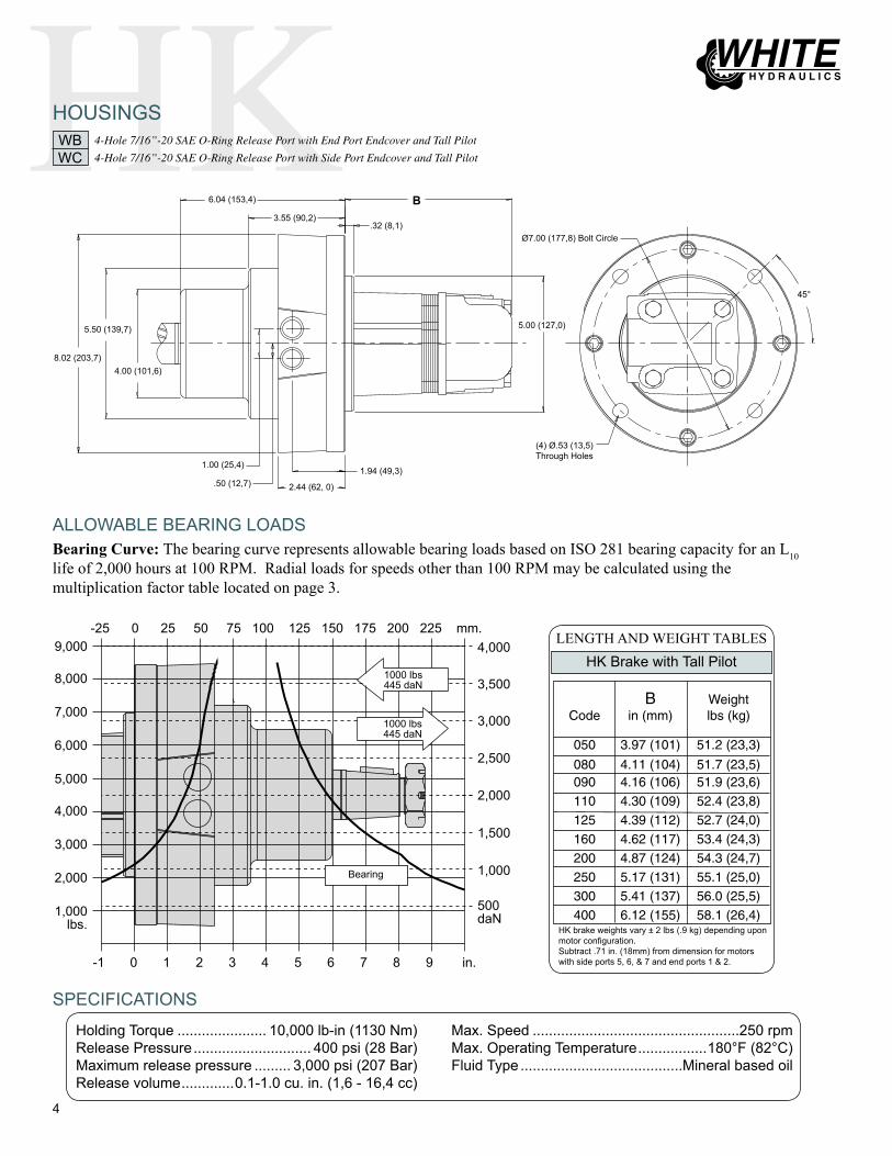
HK
4
Max. Speed ...................................................250 rpmMax. Operating Temperature .................180°F (82°C)Fluid Type ........................................Mineral based oil
4,000
3,500
3,000
2,500
2,000
1,500
1,000
500daN
9,000
8,000
7,000
6,000
5,000
4,000
3,000
2,000
1,000lbs.
-25 0 25 50 75 100 125 150 175 200 225 mm.
-1 0 1 2 3 4 5 6 7 8 9 in.
1000 lbs445 daN
Bearing
1000 lbs445 daN
8.02 (203,7)4.00 (101,6)
5.00 (127,0)
45°
3.55 (90,2)
2.44 (62, 0)
1.94 (49,3)
6.04 (153,4)
.32 (8,1)
5.50 (139,7)
B
(4) Ø.53 (13,5)Through Holes
Ø7.00 (177,8) Bolt Circle
WBWC
4-Hole 7/16”-20 SAE O-Ring Release Port with End Port Endcover and Tall Pilot
4-Hole 7/16”-20 SAE O-Ring Release Port with Side Port Endcover and Tall Pilot
HOUSINGS
ALLOWABLE BEARING LOADSBearing Curve: The bearing curve represents allowable bearing loads based on ISO 281 bearing capacity for an L10 life of 2,000 hours at 100 RPM. Radial loads for speeds other than 100 RPM may be calculated using the multiplication factor table located on page 3.
B WeightCode in (mm) lbs (kg)
050 3.97 (101) 51.2 (23,3)
080 4.11 (104) 51.7 (23,5)090 4.16 (106) 51.9 (23,6)110 4.30 (109) 52.4 (23,8)125 4.39 (112) 52.7 (24,0)160 4.62 (117) 53.4 (24,3)200 4.87 (124) 54.3 (24,7)250 5.17 (131) 55.1 (25,0)300 5.41 (137) 56.0 (25,5)400 6.12 (155) 58.1 (26,4)
HK Brake with Tall PilotLENGTH AND WEIGHT TABLES
HK brake weights vary ± 2 lbs (.9 kg) depending upon motor configuration.Subtract .71 in. (18mm) from dimension for motorswith side ports 5, 6, & 7 and end ports 1 & 2.
Holding Torque ...................... 10,000 lb-in (1130 Nm)Release Pressure ............................. 400 psi (28 Bar)Maximum release pressure ......... 3,000 psi (207 Bar)Release volume .............0.1-1.0 cu. in. (1,6 - 16,4 cc)
SPECIFICATIONS
1.00 (25,4)
.50 (12,7)
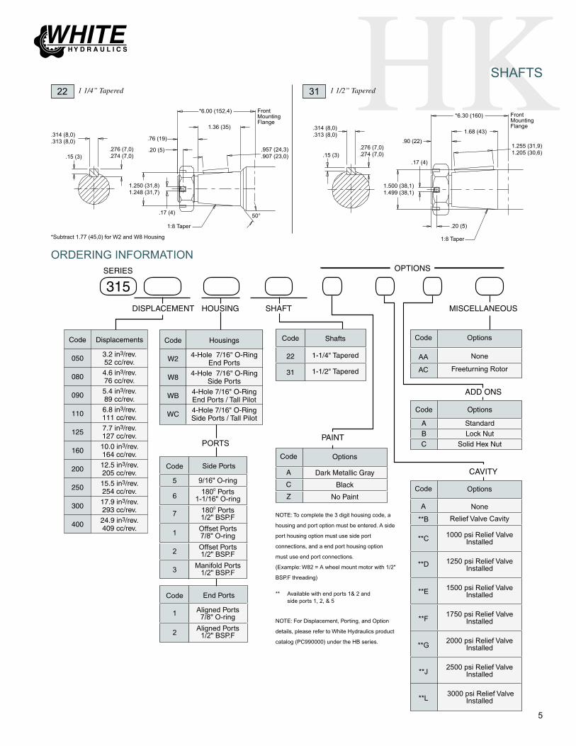
HK
5
SHAFTS
1:8 Taper
50°
.314 (8,0)
.313 (8,0)
.15 (3)
22 1 1/4” Tapered 31 1 1/2” Tapered
FrontMountingFlange
Code
050
080
090
110
125
160
200
250
300
400
Displacements
3.2 in3/rev.52 cc/rev.4.6 in3/rev.76 cc/rev.5.4 in3/rev.89 cc/rev.6.8 in3/rev.111 cc/rev.7.7 in3/rev.127 cc/rev.10.0 in3/rev.164 cc/rev.12.5 in3/rev.205 cc/rev.15.5 in3/rev.254 cc/rev.17.9 in3/rev.293 cc/rev.24.9 in3/rev.409 cc/rev.
Code
22
31
Shafts
1-1/4" Tapered
1-1/2" Tapered
Code
W2
W8
WB
WC
Housings
4-Hole 7/16" O-RingEnd Ports
4-Hole 7/16" O-RingSide Ports
4-Hole 7/16" O-RingEnd Ports / Tall Pilot4-Hole 7/16" O-RingSide Ports / Tall Pilot
DISPLACEMENT
315SHAFTHOUSING
SERIES
MISCELLANEOUS
OPTIONS
Code
A
C
Z
Options
Dark Metallic Gray
Black
No Paint
PAINT
CAVITY
ADD ONS
Code
ABC
Options
StandardLock Nut
Solid Hex Nut
** Available with end ports 1& 2 and side ports 1, 2, & 5
Code
5
6
7
1
2
3
Side Ports
9/16" O-ring
1800 Ports1-1/16" O-ring
1800 Ports1/2" BSP.F
Offset Ports7/8" O-ring
Offset Ports1/2" BSP.F
Manifold Ports1/2" BSP.F
Code
1
2
End Ports
Aligned Ports7/8" O-ring
Aligned Ports1/2" BSP.F
PORTS
NOTE: To complete the 3 digit housing code, a
housing and port option must be entered. A side
port housing option must use side port
connections, and a end port housing option
must use end port connections.
(Example: W82 = A wheel mount motor with 1/2"
BSP.F threading)
NOTE: For Displacement, Porting, and Option
details, please refer to White Hydraulics product
catalog (PC990000) under the HB series.
Code
A
**B
**C
**D
**E
**F
**G
**J
**L
Options
None
Relief Valve Cavity
1000 psi Relief Valve Installed
1250 psi Relief Valve Installed
1500 psi Relief Valve Installed
1750 psi Relief Valve Installed
2000 psi Relief Valve Installed
2500 psi Relief Valve Installed
3000 psi Relief Valve Installed
Code
AA
AC
Options
None
Freeturning Rotor
ORDERING INFORMATION
.276 (7,0)
.274 (7,0)
1.250 (31,8)1.248 (31,7)
.17 (4)
.20 (5)
.76 (19)
*6.00 (152,4)
1.36 (35)
.957 (24,3)
.907 (23,0)
1:8 Taper
.314 (8,0)
.313 (8,0)
.15 (3).276 (7,0).274 (7,0)
1.500 (38,1)1.499 (38,1)
.17 (4)
.20 (5)
.90 (22)
*6.30 (160)
1.68 (43)
1.255 (31,9)1.205 (30,6)
*Subtract 1.77 (45,0) for W2 and W8 Housing
FrontMountingFlange

White Hydraulics, Inc.P.O. Box 1127
Hopkinsville, KY. USA 42241Phone: 270 885 1110
Fax: 270 886 [email protected]
White Hydraulics GmbHHalskestrasse 15
D-40880 Ratingen, GermanyPhone: +49 2102-1237770
Fax: +49 [email protected]
White Hydraulics, Inc.Asian Distribution Center
Unit 18, 9/F.,Corporation Park11 on Lai Street, Siu Lek Yuen
Shatin, N.T. Hong KongPhone: +852 2637 6682
Fax: +852 2637 [email protected]
Low Speed, High Torque Hydraulic Motors& Drive Products
PC990315 rev. 8.05www.whitehydraulics.com

46
CE
120160200230260300350375470540750
12 1616 2016 2016 2018 2420 2520 2520 2520 2520 2520 25
3000 3250 35003000 3250 35003000 3250 35003000 3250 35003000 3250 35003000 3250 35003000 3250 35003000 3250 35002500 2750 30002000 2500 30001500 1750 2000
7.49.912.414.215.918.321.222.828.332.745.6
360 490370 470300 370260 320260 350250 320220 270200 250160 200140 170100 130
1 2 1 2 1 2 3
2850 31503750 44304650 52504950 57206250 67307100 76308000 90008600 92009200 102008875 107009575 10950
1 2
Code
Displacement(in3/rev)
Max. Speed (RPM) - 1)Cont 2)Inter.
Max. Flow (GPM) - 1)Cont 2)Inter.
Max. Torque (lb-in) - 1)Cont 2)Inter.
Max. Pressure (PSI) - 1)Cont 2)Inter. 3)Peak
SPECIFICATIONS
The combination of compact size, light weight and lowspeed efficiency make the CE motor the best wheeldrive motor available. To reduce overall motor lengthand weight, all unnecessary material was removed fromthe housing and the valve was placed in the face of therotor. The pressure-compensated balance plate allowsthe motor to maintain high volumetric efficiences atstartup and high mechanical efficiencies during runningconditions. All of these features unite to make the CESeries motor 10-25% lighter and more compact thancompetitive designs, making it perfect for applicationswith strict weight and size requirements.
12 3
5
4
Needle Roller Bearing is in optimum location toallow load to be placed as close to center line ofbearing as possible.
Three Bearing Options allow load carryingcapability of motor to be matched to application.
Pressure-Compensated Balance Plate improvesvolumetric efficiency at low flows and high pres-sure.
Valve-In-Rotor Design provides cost effective,efficient distribution of oil and reduces overall motorlength.
High Pressure Viton® Shaft Seal offers superiorseal life and performance.
2
3
4
5
1
FEATURES
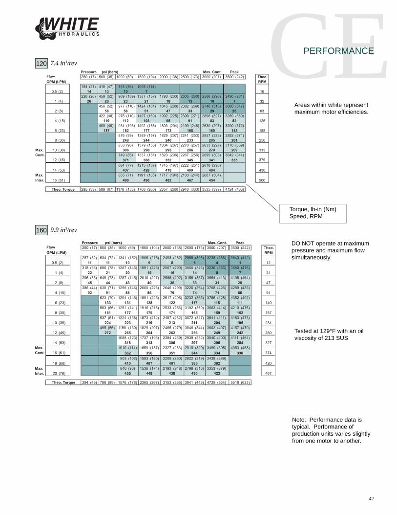
47
CEPERFORMANCE
Note: Performance data istypical. Performance ofproduction units varies slightlyfrom one motor to another.
Torque, lb-in (Nm)Speed, RPM
Areas within white representmaximum motor efficiencies.
DO NOT operate at maximumpressure and maximum flowsimultaneously.
Tested at 129°F with an oilviscosity of 213 SUS
120 7.4 in3/rev
160 9.9 in3/rev
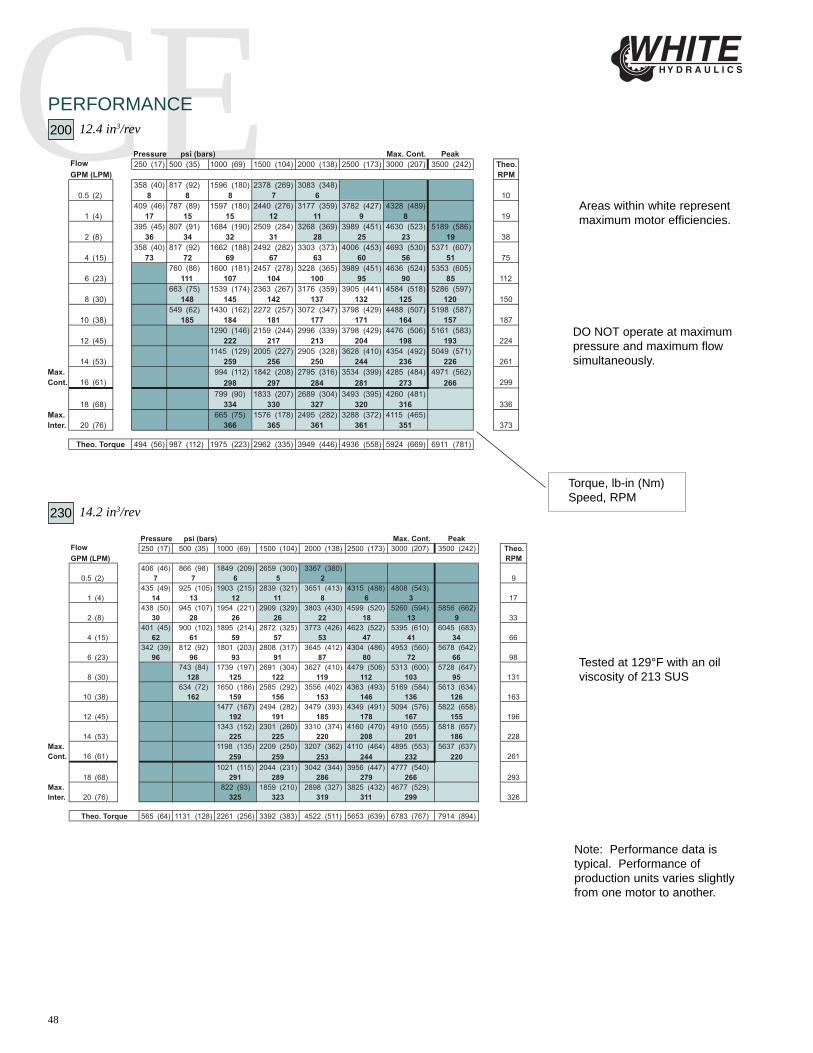
48
CEPERFORMANCE200 12.4 in3/rev
Note: Performance data istypical. Performance ofproduction units varies slightlyfrom one motor to another.
Torque, lb-in (Nm)Speed, RPM
Areas within white representmaximum motor efficiencies.
DO NOT operate at maximumpressure and maximum flowsimultaneously.
Tested at 129°F with an oilviscosity of 213 SUS
230 14.2 in3/rev

49
CEPERFORMANCE260 15.9 in3/rev
Note: Performance data istypical. Performance ofproduction units varies slightlyfrom one motor to another.
Torque, lb-in (Nm)Speed, RPM
Areas within white representmaximum motor efficiencies.
DO NOT operate at maximumpressure and maximum flowsimultaneously.
Tested at 129°F with an oilviscosity of 213 SUS
300 18.3 in3/rev
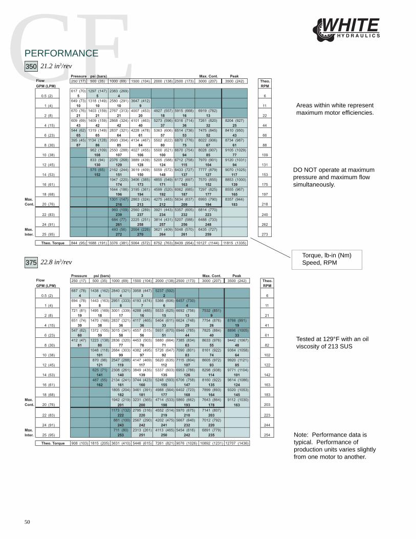
50
CEPERFORMANCE350 21.2 in3/rev
Note: Performance data istypical. Performance ofproduction units varies slightlyfrom one motor to another.
Torque, lb-in (Nm)Speed, RPM
Areas within white representmaximum motor efficiencies.
DO NOT operate at maximumpressure and maximum flowsimultaneously.
Tested at 129°F with an oilviscosity of 213 SUS
375 22.8 in3/rev

51
CEPERFORMANCE470 28.3 in3/rev
Note: Performance data istypical. Performance ofproduction units varies slightlyfrom one motor to another.
Torque, lb-in (Nm)Speed, RPM
Areas within white representmaximum motor efficiencies.
DO NOT operate at maximumpressure and maximum flowsimultaneously.
Tested at 129°F with an oilviscosity of 213 SUS
540 32.7 in3/rev

52
CEPERFORMANCE750 45.6 in3/rev
Note: Performance data istypical. Performance ofproduction units varies slightlyfrom one motor to another.
Torque, lb-in (Nm)Speed, RPM
Areas within white representmaximum motor efficiencies.
DO NOT operate at maximumpressure and maximum flowsimultaneously.
Tested at 129°F with an oilviscosity of 213 SUS

53
400.524.514
3.2493.246
.90
.61
4.9994.994
1.4931.483
5.45 Max.
Ø 5.81245°
2.47 Min.
5.21 Max.
.90
.10 Min.
1.47
A
B
5.45 Max..524.514
5.21 Max.
2.2545°
Ø 5.812
4.13
.71
1.17
Valve Cavity - 10 Series/2-way (7/8”-14 UNF-2B)
2.47 Min.
WHEEL MOUNT
Optional Relief Cartridge shown installed and is available for both the W31 and W38 housings.
4-Hole Front Aligned Ports 7/8” O-Ring
4-Hole Front Aligned Ports 1/2” BSP.F
W31
W38I
I
I is on page 54
HOUSINGS

54
4008,000
7,000
6,000
5,000
4,000
3,000
2,000
1,000lbs.
3,500
3,000
2,500
2,000
1,500
1,000
500DaN
-75 -50 -25 0 25 50 75 100 125 mm
-3 -2 -1 0 1 2 3 4 5 in.
WHEEL MOUNT
1000 lbs
1000 lbs
Bearing
Shaft
SHAFTS
20 1¼” Straight
15°
1.4751.425
*4.03
2.14
1.90
5/8”-18 UNF
1.2501.249
.32
.83 Min..276.274
1.33Wire Ring
1.3881.376
.314
.313
Ø .06Wire Ring
MountingFlange
Note: A slotted nut is standard on this shaft.
.957
.907
1.37*3.94
1”-20 UNEF
1:8 Taper
.75
.17
1.2501.248
.15
.276
.274
.314
.313
5/8”-18 UNF14 tooth 12/24 PitchStd. ANSI B92.1-1996 Spline
1.2491.245
.83 Min.1.60 Min.
1.90
15°
.20
23 14 Tooth Spline
Max. Torque: 10600 lb-in
22 1¼” Tapered
Max. Torque: 10600 lb-in
MountingFlange
Wire Ring1.33
Ø .06Wire Ring
MountingFlange
*Note: Shaft lengths may vary by ± .030 in
ALLOWABLE BEARING AND SHAFT LOADSBearing Curve: The bearing curve represents allowable bearing loadsbased on ISO 281 bearing capacity for an L10 life of 2,000 hours at100 RPM. Radial loads for speeds other than 100 RPM may becalculated using the multiplication factor table located on page 24.
TECHNICAL
I WeightCode in lbs
120 3.91 24.1
160 3.91 24.1200 4.05 24.8
230 4.15 25.2
260 4.24 25.6
300 4.37 26.3
350 4.92 28.8375 4.62 27.4
470 4.92 28.8
540 5.16 30.0
750 5.87 33.1CE motor weights vary ± 1 lb depending upon motorconfiguration.
Wheel Mount
LENGTH AND WEIGHT TABLES
Max. Torque: 10600 lb-in
*4.03

55
400For applications requiring the motor to rotate in only one direction, shaft seal life may beprolonged by pressurizing the “A” port of the motor. To obtain the desired direction ofshaft rotation, use the graphic at the left to determine the rotation code for the motor. Forbi-directional applications, the 400 series is recommended. Preferred rotation is deter-mined by internal valving design.
B A
400 401
B A
SHAFT ROTATION
Housing
4-Hole FrontPorts 1/2" BSP.F
4-Hole Front Ports7/8" O-ring
Code
W38
W31
Code
22
20
23
Shafts
1-1/4" Tapered
1-1/4" Straight
14 Tooth Spline
*Must use W31 or W38 Housing.
DISPLACEMENT
400401
SHAFTHOUSING
SERIES
REVERSED TIMING
Code
120160200230260300350375470540750
Displacement
7.4 in3/rev9.9 in3/rev12.4 in3/rev14.2 in3/rev15.9 in3/rev18.3 in3/rev21.2 in3/rev22.8 in3/rev28.3 in3/rev32.7 in3/rev45.6 in3/rev
Code
A
B
C
D
Z
Options
Dark Metallic Gray
Dark Metallic Gray(Unpainted Flange Face)
Black
Black (Unpainted Flange Face)
No Paint
MISCELLANEOUS
OPTIONS
PAINT ADD ONS
Code
A
B
C
Options
Standard
Lock Nut
Solid Hex Nut
CAVITY
Code
A
*B
*C
*D
*E
*F
*G
*J
*L
Options
None
Relief Valve Cavity
1000 psi Relief Valve Installed
1250 psi Relief Valve Installed
1500 psi Relief Valve Installed
1750 psi Relief ValveInstalled
2000 psi Relief Valve Installed
2500 psi Relief Valve Installed
3000 psi Relief Valve Installed
Code
AA
AC
AE
Options
None
Freeturning Rotor
Hydraulic Declutch (With Freeturning Rotor)
ORDERING INFORMATION

56
420WHEEL MOUNT
4-Hole Front Aligned Ports 9/16” O-Ring
4-Hole Front Aligned Ports 1/2” BSP.F
W35
W38
H
.524
.514
3.4983.494
.90
.72
4.9984.994
1.7431.738
5.45 Max.
Ø 5.812
45°
2.49 Min.
5.15 Max.
.90
.10 Min.
1.48
W31 4-Hole Front Aligned Ports 7/8” O-Ring
H is on page 57
HOUSINGS

57
420SHAFTS
22 1 ¼” Tapered
8,000
7,000
6,000
5,000
4,000
3,000
2,000
1,000lbs.
3,500
3,000
2,500
2,000
1,500
1,000
500DaN
-3 -2 -1 0 1 2 3 4 5 in.
-75 -50 -25 0 25 50 75 100 125 mm
.890
.880
1.37
*4.26
1”-20 UNEF
1:8 Taper
.76
.17
1.2411.240
.15
.276
.274
.314
.313.20
Max. Torque: 10600 lb-in
MountingFlange
*Shaft Lengths may vary ± .030 in
WHEEL MOUNT
1000 lbs
1000 lbs
Bearing
Shaft
TECHNICAL
H WeightCode in lbs
120 3.91 24.1
160 3.91 24.1200 4.05 24.8
230 4.15 25.2
260 4.24 25.6
300 4.37 26.3
350 4.92 28.8375 4.62 27.4
470 4.92 28.8
540 5.16 30.0
750 5.87 33.1CE motor weights vary ± 1 lb depending upon motorconfiguration.
Wheel Mount
LENGTH AND WEIGHT TABLES
ALLOWABLE BEARING AND SHAFT LOADSBearing Curve: The bearing curve represents allowable bearing loads based on ISO 281 bearing capacity for an L10life of 2,000 hours at 100 RPM. Radial loads for speeds other than 100 RPM may be calculated using the multiplica-tion factor table located on page 24.
Note: A slotted nut is standard on this shaft.
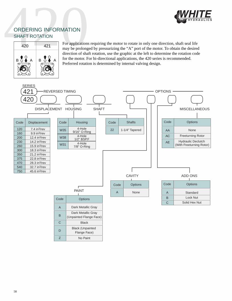
58
420For applications requiring the motor to rotate in only one direction, shaft seal lifemay be prolonged by pressurizing the “A” port of the motor. To obtain the desireddirection of shaft rotation, use the graphic at the left to determine the rotation codefor the motor. For bi-directional applications, the 420 series is recommended.Preferred rotation is determined by internal valving design.
B A
420 421
B A
SHAFT ROTATIONORDERING INFORMATION
Housing
4-Hole9/16" O-Ring
4-Hole1/2" BSP.F
4-Hole7/8" O-Ring
Code
W35
W38
W31
Code
22
Shafts
1-1/4" Tapered
DISPLACEMENT
420421
SHAFTHOUSING
SERIES
REVERSED TIMING
Code
A
B
C
D
Z
Options
Dark Metallic Gray
Dark Metallic Gray(Unpainted Flange Face)
Black
Black (Unpainted Flange Face)
No Paint
MISCELLANEOUS
OPTIONS
PAINT
ADD ONS
Code
A
B
C
Options
Standard
Lock Nut
Solid Hex Nut
CAVITY
Code
AA
AC
AE
Options
None
Freeturning Rotor
Hydraulic Declutch (With Freeturning Rotor)
Code
120160200230260300350375470540750
Displacement
7.4 in3/rev9.9 in3/rev12.4 in3/rev14.2 in3/rev15.9 in3/rev18.3 in3/rev21.2 in3/rev22.8 in3/rev28.3 in3/rev32.7 in3/rev45.6 in3/rev
Code
A
Options
None

59
430WHEEL MOUNT
J is on page 60
.524
.514
3.2493.246
.90
.61
4.9994.994
1.4931.483
5.45 Max.
Ø 5.812
45°
2.47 Min.
5.21 Max.
.90
.10 Min.
1.47
A
B
5.45 Max..524.514
5.21 Max.
2.2545°
Ø 5.812
4.13
.71
1.17
Valve Cavity - 10 Series/2-way (7/8”-14 UNF-2B)
2.47 Min.
Optional Relief Cartridge shown installed and is available for both the W31 and W38 housings.
4-Hole Front Aligned Ports 7/8” O-Ring
4-Hole Front Aligned Ports 1/2” BSP.F
W31
W38 J
J
HOUSINGS

60
430
8,000
7,000
6,000
5,000
4,000
3,000
2,000
1,000lbs.
3,500
3,000
2,500
2,000
1,500
1,000
500DaN
-75 -50 -25 0 25 50 75 100 125 mm
-3 -2 -1 0 1 2 3 4 5 in.
SHAFTS
31 1 ½” Tapered
Max. Torque: 10600 lb-in
1000 lbs
1000 lbs
Bearing
Shaft
28 35mm Tapered
Max. Torque: 10600 lb-in
.900
.890
1.72
*4.59
1-1/8”-18 UNEF 1:8 Taper
.75
.17
1.5001.499
.15
.276
.274
.314
.313.20
MountingFlange
.900
.890
1.42
*4.20
M24 x 1.5 Thread
1:10 Taper
.87
.19
1.3781.358
.15
.276
.274
.314
.313 .12
MountingFlange
*Shaft Lengths may vary ± .030 in
TECHNICAL
WHEEL MOUNT
J WeightCode in lbs
120 3.91 24.1
160 3.91 24.1200 4.05 24.8
230 4.15 25.2
260 4.24 25.6
300 4.37 26.3
350 4.92 28.8375 4.62 27.4
470 4.92 28.8
540 5.16 30.0
750 5.87 33.1CE motor weights vary ± 1 lb depending upon motorconfiguration.
Wheel Mount
LENGTH AND WEIGHT TABLES
ALLOWABLE BEARING AND SHAFT LOADSBearing Curve: The bearing curve represents allowable bearing loads based on ISO 281 bearing capacity for an L10life of 2,000 hours at 100 RPM. Radial loads for speeds other than 100 RPM may be calculated using the multiplica-tion factor table located on page 24.
Note: A slotted nut is standard on this shaft.
Note: A slotted nut is standard on this shaft.

61
430For applications requiring the motor to rotate in only one direction, shaft seal life may beprolonged by pressurizing the “A” port of the motor. To obtain the desired direction ofshaft rotation, use the graphic at the left to determine the rotation code for the motor. Forbi-directional applications, the 430 series is recommended. Preferred rotation is deter-mined by internal valving design.
B A
430 431
B A
ORDERING INFORMATIONSHAFT ROTATION
Code
A
*B
*C
*D
*E
*F
*G
*J
*L
Options
None
Relief Valve Cavity
1000 psi Relief Valve Installed
1250 psi Relief Valve Installed
1500 psi Relief Valve Installed
1750 psi Relief ValveInstalled
2000 psi Relief Valve Installed
2500 psi Relief Valve Installed
3000 psi Relief Valve Installed
Code
120160200230260300350375470540750
Displacement
7.4 in3/rev9.9 in3/rev
12.4 in3/rev14.2 in3/rev15.9 in3/rev18.3 in3/rev21.2 in3/rev22.8 in3/rev28.3 in3/rev32.7 in3/rev45.6 in3/rev
Code
31
28
Shafts
1-1/2" Tapered
35mm Tapered
Housing
4-Hole FrontPorts 1/2" BSP.F
4-Hole Front Ports7/8" O-ring
Code
W38
W31
DISPLACEMENT
430431
SHAFTHOUSING
SERIES
REVERSED TIMING
*Must use W31 or W38 Housing.
Code
A
B
C
D
Z
Options
Dark Metallic Gray
Dark Metallic Gray(Unpainted Flange Face)
Black
Black (Unpainted Flange Face)
No Paint
MISCELLANEOUS
OPTIONS
PAINT ADD ONSCAVITY
Code
AA
AC
AE
Options
None
Freeturning Rotor
Hydraulic Declutch (With Freeturning Rotor)
Code
A
B
C
Options
Standard
Lock Nut
Solid Hex Nut

62
4101”-20 UNEF Nut
3.12
1.10
4.9994.994
1.47
6.18
6.75
7.38
(5) ½”-20 SAE Mounting Studson a Ø 4.5” Bolt Circle
2.05
4.49
X
5.45
5.21
(4) Ø 0.52” on aØ 5.81 Bolt Circle
.66
.90
1.80
.71
High Efficiency CE series Motor provides exceptionallow speed performance in one of the smallest wheeldrive packages available todaySelf-Adjusting Brake Mechanism makes brakeadjustments unnecessary by automatically adjusting forbrake wearStandard Wheel Mount Flange adapts easily to newdesigns and can be retro-fitted onto older machines4 and 5 Bolt Wheel Hubs are available to accomodatea wide variety of wheel rimsLabyrinth Lip Design incorporated into hub helpsprotect brake components from elements2-Position Brake Lever provides flexibility in theattachment of brake cables or actuating linkage
4-Hole Aligned Ports 9/16” O-Ring with Brake Mount
4-Hole Aligned Ports 1/2” BSP.F with Brake Mount
K35
K38
K31 4-Hole Aligned Ports 7/8” O-Ring with Brake Mount
HOUSINGS
SHAFTS
22 1 ¼” Tapered
.890
.880
1.37
1”-20 UNEF
1:8 Taper
.76
1.2411.240
.15
.276
.274
.314
.313
Max. Torque: 10600 lb-in
FEATURES
X is on page 63

63
410
0 20 40 60 80 100 120 140 160 180 200
5,500
5,000
4,500
4,000
3,500
3,000
2,500
2,000
1,500
1,000
500
0
Cable Force (lbsf)
Bra
ke T
orqu
e (lb
-in)
ReverseForward
BRAKE HOLDING TORQUE
-9 -8 -7 -6 -5 -4 -3 -2 -1 0 1 2 in.
-225 -200 -175 -150 -125 -100 -75 -50 -25 0 25 50mm
9,000
8,000
7,000
6,000
5,000
4,000
3,000
2,000
1,000lbs.
4,000
3,500
3,000
2,500
2,000
1,500
1,000
500DaN
1000 lbs
1000 lbs
Bearing
WHEEL MOUNT WITH BRAKE
X WeightCode in lbs
120 3.91 35.2
160 3.91 35.2200 4.05 35.9
230 4.15 36.3
260 4.24 36.7
300 4.37 37.4
350 4.92 39.9375 4.62 38.5
470 4.92 39.9
540 5.16 41.1
750 5.87 44.2CE motor weights vary ± 1 lb depending upon motorconfiguration.
Wheel Mount
LENGTH AND WEIGHT TABLES
ALLOWABLE BEARING AND SHAFT LOADSBearing Curve: The bearing curve represents allowable bearing loads based on ISO 281 bearing capacity for an L10life of 2,000 hours at 100 RPM. Radial loads for speeds other than 100 RPM may be calculated using the multiplica-tion factor table located on page 24.
TECHNICAL

64
410
For applications requiring the motor to rotate in only one direction, shaft seal life may beprolonged by pressurizing the “A” port of the motor. To obtain the desired direction ofshaft rotation, use the graphic at the left to determine the rotation code for the motor. Forbi-directional applications, the 410 series is recommended. Preferred rotation is deter-mined by internal valving design.
B A
410 411
B A
SHAFT ROTATION
ORDERING INFORMATION
Housing
4-Hole w/Brake Mount
7/8" O-Ring
4-Holew/Brake Mount
1/2" BSP.F
4-Holew/Brake Mount9/16" O-Ring
Code
K31
K38
K35
Code
22
Shafts
1-1/4" Tapered
DISPLACEMENT
410411
SHAFTHOUSING
SERIES
REVERSED TIMING
MISCELLANEOUS
OPTIONS
ADD ONS
Code
A
Options
Standard
Code
A
C
Z
Options
Dark Metallic Gray
Black
No Paint
PAINT CAVITY
Code
A
Options
None
Code
ZA
YA
ZE
YE
Options
Brake Drum Left HandPosition 1, 5 Bolt Hub
Brake Drum Right HandPosition 2, 5 Bolt Hub
Brake Drum Left HandPosition 1, 4 Bolt Hub
Brake Drum Right HandPosition 2, 4 Bolt Hub
Code
120160200230260300350375470540750
Displacement
7.4 in3/rev9.9 in3/rev
12.4 in3/rev14.2 in3/rev15.9 in3/rev18.3 in3/rev21.2 in3/rev22.8 in3/rev28.3 in3/rev32.7 in3/rev45.6 in3/rev