1 introduction to switching systems
TRANSCRIPT
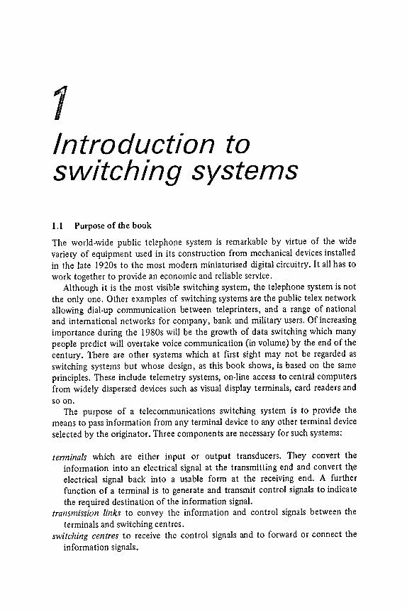
1Introduction toswitching systems
tenninals which are either input or output transducers. They convert theinformation into an electrical signal at the transmitting end and convert tl"\eelectrical signal back into a usable form at the receiving end. A furilierfunction of a terminal is to generate and transmit control signals to indicatethe required destination of the information signal.
transmission links to convey the information and control signals between theterminals and switching centres.
switching centres to receive the control signals and to forward or connect theinformation signals.
1.1 Purpose of the book
The world -wide public telephone system is remarkable by virtue of the widevariety of equipment used in its construction from mechanical devices installedin the late 1920s to the most modern miniaturised digital circuitry . It all has towork together to provide an economic and reliable service.
Although it is the most visible switching system, the telephone system is notthe only one. Other examples of switching systems are the public telex networkallowing dial-up communication between teleprinters, and a range of nationaland international networks for company, bank and military users. Of increasingimportance during the 1980s will be the growth of da ta switching which manypeople predict will overtake voice communication ( in volume) by the end of thecentury . There are other systems which at first sight may not be regarded asswitching systems but whose design, as this book shows, is based on the sameprinciples . These include telemetry systems, on-line access to central computersfrom widely dispersed devices such as visual display terminals, card readers andsoon .
The purpose of a telecommunications switching system is to provide themeans to pass information from any terminal device to any other terminal deviceselected by the originator . Three components are necessary for such systems:
2 INTRODUCTION TO SWITCHING SYSTEMS
Transmission links are covered in detail in a companion volume [ 1] and receiveonly scant mention in this book . Terminals are covered only from the point ofview of their capabilities to generate and receive the control signals. The bookdeals with the design of the individual switching centres and their incorporationin switching networks .
The organisation of this book has two aims:
( 1) To show that there is a unified set of principles behind the wide range ofsuperficially different switching centre designs, and to show how theseprinciples may be applied to switching centre design using modern technology
.
(2) To give a description of the implementation of the design principles insome of the switching centre types in use today .
This chapter introduces the basic systems concepts and the objectives of asystem design. Chapter 2 describes the basic signalling and switching techniqueused in voice and data switching centres. The design of economic switchingcentres is covered in Chapter 3. Economic design involves resource sharing andresource sharing implies that there is a probability that a resource (such as aswitch or a transmission link ) will not be available at the instant it is required.The design of a switching centre therefore involves determining the number ofresources required to achieve a particular probability of no resource beingavailable (and possibly a particular length of wait for a resource to becomeavailable) . This is the subject of traffic theory which is covered in Chapter 4.
Switching centres are organised in networks and these are discussed inChapter 5. The practical means by which control signals are passed from centreto centre are the subject of Chapter 6.
The next two chapters are more theoretical and in Chapter 7 a coherentapproach is given to the design of switch networks . Of particular importance inthis chapiter is a discussion of the work of Takagi on optimum channel graphs. Itis thought that this is the first time that this treatment has been covered in a textbook .
Chapter 8 is a theoretical approach to the design of control systems andattempts to show a unified approach to the design of electronic and computercontrol led systems and the relationship to signalling systems.
After the theoretical chapters, the remainder of the book deals with practicalaspects of telephone switching systems. Chapter 9 describes a wide range of thepractical techniques used within electromechanical and electronic systems. Aselection of electromechanical and electronic systems are described in Chapter10 and the examples are carefully chosen to demonstrate the application ofparticular principles. Computer control led systems have Chapter 11 to themselves
and some of this chapter requires a basic knowledge of computers.
The long-term future for the technology of switching systems is almostcertainly going to be digital and the basic differences to other systems togetherwith an example are discussed in Chapter 12.

TYPES OF SWITCHING SYSTEMS 3
Finally , the author has allowed himself some licence and the last chapter is inthe form of an editorial , which attempts to predict the future direction ofsystem architectures. This chapter attempts to show that the centralised controlsystems origins come from the 1960s and are not the way today 's systemsshould be-designed. The centralised systems appear to have been designed as anexercise in programming rather than as the design of a reliable telephoneswitching system using principles described in this book . Time will show whowas right .
1.2 Types of switchhlg systems
A system similar to (but smaller than) the telephone network is t)le public telexnetwork (telegraph exchange) which provides world -wide direct interconnectionof teleprinters . Both the telephone and telex networks are examples of what arecalled circuit switching since they set up a circuit between two terminals whichthen interchange information directly .
Another class of system which is more familiar to the business or militaryuser is that of message switching . The terminals of message switched systems areusually teleprinters , but unlike the telex network they are not interconnecteddirectly . Instead, when a terminal user types a message destined for some otherterminal , the system stores the message and delivers it to the required terminal atsome later time . The reason for the delay is that the system is designed tomaximise the utilisation of transmission links by queueing messages awaiting theuse of a link . In order to set up a direct connection over many links connectedend-to-end it is necessary for each link to be simultaneously free. As will be seenlater , this implies that the average utilisation of the links must be low if the
probability of a direct connection being available on demand is to be highenough to satisfy most users. llowever , in a message switched system, wheremessages are queued for each link , a much higher link utilisation is achieved.Another name for this type of system is store and forward switching.
The advent of real-time computer systems for airline reservation, bankingsystems and remote data processing in general has been based on the use oftelecommunications networks to carry data between computer-type terminaldevices and large real-time computers. Such applications may be served bya purpose-built circuit switched network or by another system such as thepublic telephone network in conjunction with special signal processingtechniques.
More recently , general purpose packet switching systems have been developedwhich take the data from a terminal or a computer and transmit it as shortpackets of information to the required destination . Such systems are midwaybetween the two extremes of circuit switching and store and forward . Theinterchange of packets may be made so rapid that a terminal appears to providea 'conversational' connection while at the same time high transmission linkutilisations are obtained through queueing.
terminal 1
(a)
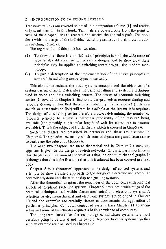
An alternative approach which needs only N links is to provide one link perterminal and to arrange that all other terminals have access to it as shown inFigure l . lb . This simplifies the terminal equipment because it removes the needto connect a terminal to a link for an incoming call. This is a practicalarrangement for systems such as house telephones or intercoms where there is arelatively small number of terminals close together. For instance, it is possible toprovide an eleven-terminal system with each terminal having ten buttons andeleven pairs of wires going around to each instrument . However, when thenumber of terminals increases, or their geographical separation increases, thecost of cabling makes this arrangement uneconomic. Another example of thetechnique illustrated in Figure 1.1 b is a radio telephone network in which eachterminal is given its own frequency. An originator can set-up a call by tuning histransmitter to the frequency of the called terminal .
4 INTRODUCTION TO SWITCHING SYSTEMS
1.3 Centralised switching systems
A simple way of structuring a switched network is to arrange that each terminalhas a direct transmission link to every other terminal , as shown in Figure I .Ia .Each terminal needs a switch to connect it to the required link and a switch tomake connection to a link in order to receive an incoming call. For N terminalsthis arrangement needs a total of Yin(N - 1) links .
Figure 1.1 (a) Full interconnection for five terminals. Some form of switching isneeded within each terminal to connect it to the appropriate link . (b) Use of onechannel per terminal . Each terminal is permanently connected to one channel andall other terminals may access a particular terminal by operatin~ a switch whichconnects it to the appropriate channel. (c) As in (b) but with less than Nchannels.

It is possible to use an arrangement similar to that just described but withfewer than N links , as shown in Figure 1.lc . With this arrangement it is necessaryfor the calling terminal to select a free link and for the called terminal to beconnected to the same link . One technique used extensively for radio telephonesinvolves a common channel to which all free terminals are connected [2] . Acalling signal (which may be coded or verbal) is sent along this link and isreceived by the terminals. The calling signal informs the called terminal (or itsuser) of an incoming call and indicates the link to which the terminal should beswitched in order to receive the call. The recognition of the calling signal and theswitching operations may be performed automatically in a system using codedsignals. In simpler systems the users may be required to listen out for , and actupon, verbal calling signals.
At the present time this technique of 'distributed ' switching is applied only tosmall telephone systems and to some radio telephone networks . One of thepossibilities of the future is what is called a 'digital ring main' in which a highspeed binary digital link is connected to a large number of tenninals. Similartechniques to that described above may then be used. For example, a terminalcould connect itself to a free time slot within the digital bit stream in order toset up a communication path to the called terminal .
CENTRALISED SWITCHING SYSTEMS 5
order
I - - - - - - r - - - - - - - - - - - - - I channel
I I I ] M
! 11 r 1 I I 11 i 1 channels" "
a
(c)
- - control signals
6 INTRODUCTION TO SWITCHING SYSTEMS
~ ~- ---.--- --,. I
~ ~~nal ~J."...-
. /
information link
(a)
Trunk links between
switching machines .shared between allterminals as needed
(b)
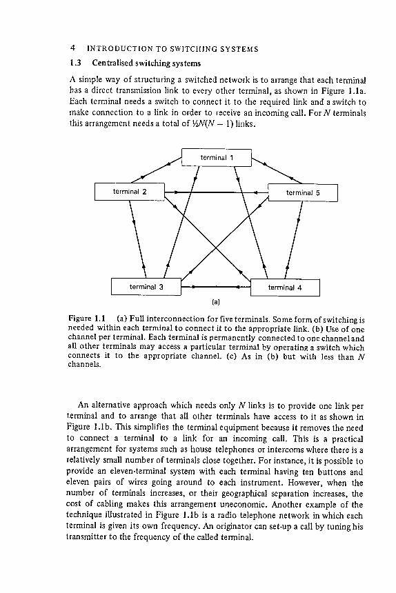
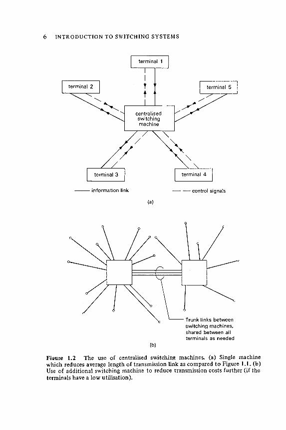
Firure 1.2 The use of centralised switching machines. (a) Single machine~which reduces average length of transmission link as compared to Figure 1.1. (b)Use of additional switching machine to reduce transmission costs further (if theterminals have a low utilisation ).
CENTRALISED SWITCHING SYSTEMS 7
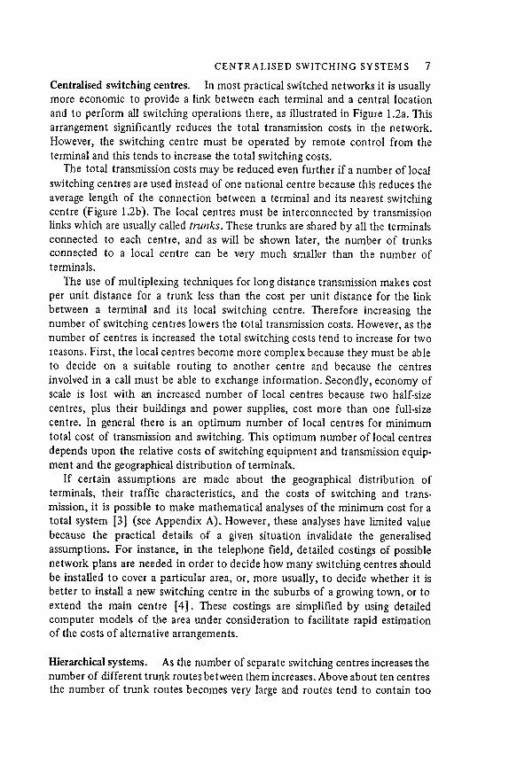
Centra Ilsed switching centres. In most practical switched networks it is usuallymore economic to provide a link between each terminal and a central locationand to perform all switching operations there, as illustrated in Figure 1.2a. Thisarrangement significantly reduces the total transmission costs in the network .However, the switching centre must be operated by remote control from theterminal and this tends to increase the total switching costs.
The total transmission costs may be reduced even further if a number of local
switching centres are used instead of one national centre because this reduces the
average length of the connection between a terminal and its nearest switchingcentre (Figure 1.2b) . The local centres must be interconnected by transmissionlinks which are usually called trunks . These trunks are shared by all the terminalsconnected to each centre , and as will be shown later , the number of trunks
connected to a local centre can be very much smaller than the number ofterminals .
The use of multiplexing techniques for long distance transmission makes ~ostper unit distance for a trunk less than the cost per unit distance for the link
between a terminal and its local switching centre. Therefore increasing thenumber of switching cen tres lowers the total transmission costs. However, as thenumber of centres is increased the total switching costs tend to increase for tworeasons. First , the local centres become more complex because they must be ableto decide on a suitable routing to another centre and because the centres
involved in a call must be able to exchange information . Secondly, economy ofscale is lost with an increased number of local centres because two half -size
centres, plus their buildings and power supplies, cost more than one full -sizecentre. In general there is an optimum number of local centres for minimumtotal cost of transmission and switching . This optimum number of local centresdepends upon the relative costs of switching equipment and transmission equipment
and the geographical distribution of terminals .
If certain assumptions are made about the geographical distribution ofterminals, their traffic characteristics, and the costs of switching and transmission
, it is possible to make mathematical analyses of the minimum cost for atotal system [3] (see Appendix A) . However, these analyses have limited valuebecause the practical details of a given situation invalidate the generalisedassumptions. For instance, in the telephone field , detailed costings of possiblenetwork plans are needed in order to decide how many switching centres shouldbe installed to cover a particular area, or, more usually, to decide whether it isbetter to install a new switching centre in the suburbs of a growing town , or toextend the main centre [4] . These costings are simplified by using detailedcomputer models of the area under consideration to facilitate rapid estimationof the costs of alternative arrangements .
Hierarchical systems. As the number of separate switching centres increases thenumber of different trunk routes between them increases . Above about ten centres
the number of trunk routes becomes very large and routes tend to contain too
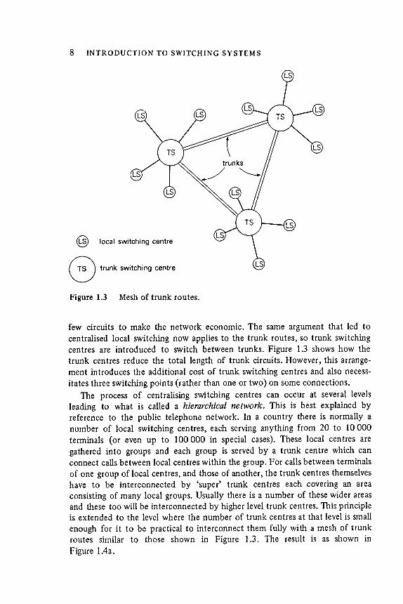
few circuits to make the network economic. The same argument that led tocentralised local switching now applies to the trunk routes, so trunk switchingcentres are introduced to switch between trunks . Figure 1.3 shows how thetrunk centres reduce the total length of trunk circuits . However, this arrangement
introduces the additional cost of trunk switching centres and also necessitates three switching points (rather than one or two ) on some connections.
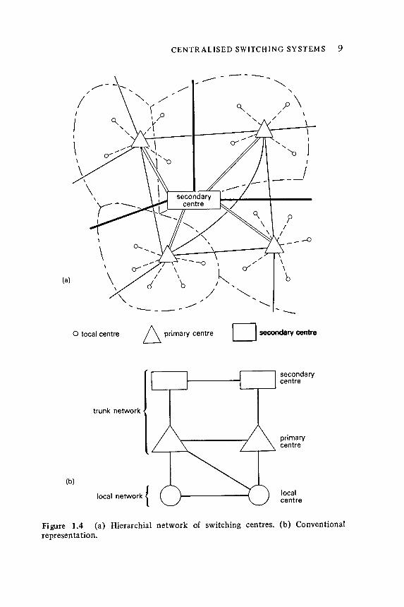
The process of centralising switching centres can occur at several levelsleading to what is called a hierarchical network . This is best explained byreference to the public telephone network . In a country there is normally anumber of local switching centres, each serving anything from 20 to 10 000terminals (or even up to 100 000 in special cases) . These local centres aregathered into groups and each group is served by a trunk centre which canconnect calls between local centres within the group. For calls between terminalsof one group of local centres, and those of another, the trunk centres themselveshave to be interconnected by 'super' trunk centres each covering an areaconsisting of many local groups. Usually there is a number of these wider areasand these too will be interconnected by higher level trunk centres. This principleis extended to the level where the number of trunk centres at that level is small
enough for it to be practical to interconnect them fully with a mesh of trunkroutes similar to those shown in Figure 1.3. The result is as shown inFigure 1.4a.
8 INTRODUCTION TO SWITCHING SYSTEMS�
@ local switching centre
G trunk switching centreFigure 1.3 Mesh of trunk routes.
-
- -
. . ....- ..." ' "
I I
{ II I
/- -
- - 0
/ '/ '
\ 0' "
\ ' "I "
/ " ". . .
..........' - - -
9CENTRALISED SWITCHING SYSTEMS
- - - - ""
\,
(a)
6 primary centre0 local centre
secondarycentre
trunk network
primarycentre
(b)
local network {localcentre
Figure 1.4 (a) Hierarchial network of switching centres. (b) Conventionalrepresent a tion .

10 INTRODUCTION TO SWITCHING SYSTEMS
Table 1.1 Names of different level switching centres in telephone networks(The numbers in brackets indicate approximate numbers in each country ( 1976).)
�
Function
Main switching
(not required in
-J
~(
1 ) ~x
0 -
n ( 1 )
g- 3
~OQ
(1 )
Tan<.iem exchange
Centre du transit 3 (or CT3)
(there are 7 of these in the international network )
In the telephone system, different countries have adopted different names forthese different levels of centre. So to simplify discussion a set of names has beeninternationally agreed [5] . Table 1.1 shows these names together with equivalent
U.K . and North American terms.
Figure 1.4b shows a conventional way of illustrating a hierarchical networkplan. It can be seen from this that a hierarchical network , as described above,
(6200)
centre centre (27)
centre (9)
centre U.K.)
�
U.K. name
Local exchange
Primary centre
Secondary
Tertiary centre
Quaternary
Centre du transit 2 (or CT2)
Centre du transit 1 (or CT 1)
Centre which
provides connections onlybetween localce Iltres (i .e. noaccess to trunknetwork )
Switching centrewhich providesaccess to international
network.
Internationaltransit centre
Top level international
transit switching centre (fully
interconnected )
Local switchingcentre directlyconnected toterminals
First level trunkswitching centre
Second leveltrunk switching
centre
Third level trunkswitching centre
Fourth level trunkswitching centre
North American
name
End office or Class 5
office ( 18 000 )
Toll centre or Class 4
office ( I 500 )
Primary centre orClass 3 office
(250 )
Sectional centre of
Class 2 office ( 65 )
Regional centre orClass 1 office ( 18in U . S . A . , 2 in
Canada )
Tandem office
Internationalname
Local Exchange
Group switchingcentre (370)
District switching
up -timeA =
up -time + down -time
where the up-time is the total time that the system is operating satisfactorily andthe down-time the total time that it is not .
An alternative and equivalent definition of availability is in terms of the meantime between failures (mit .b.f .) and the mean time to repair (mit .t .r.) :
m .t .b .f .A =
m .t .b .f . + mit .t .r .
Functions of telephone switching systems. Some of the functions of telephoneswitching will now be defined. .The local switching centre must react to a callingsignal from a terminal and must be able to receive information to identify therequired destination terminal . It must be able to decide from the input information
whether the required ter Jninal is connected to the same local centre or
whether a trunk connection is necessary via one or more intermediate trunkcentres. If an intermediate trunk centre is needed the local centre must find a
free trunk on the required trunk routes and connect the terminal to it . Furtherinformation must then be forwarded to the intermediate trunk centre or centresto progress the call to its destination .
Once a path has been set up from the originating centre to the terminatingcentre, the called terminal must be rung; and once the called party has answered,a speech path must be established between the two terminals for as long as thecall lasts.
Since public telephone systems must make money, at some stage it isnecessary to extract charging information for billing purposes.
A further requirement which is not obvious from what has been said so far is
that a telephone system must be very reliable. In the language of reliabilitymathematics, a telephone system must have a high availability . Most switchingsystems are required to give uninterrupted service for many years. Telephonesystems, for example, have design lives of from 20 to 40 years. Present technology
is such that no system can be guaranteed to be completely free of faults for
this length of time , but it is nevertheless possible to design a system to providean adequate service even in the presence of faults or malfunctions .
System reliability can be expressed mathematically in terms of availabilitydefined as:
CENTRALISED SWITCHING SYSTEMS 11
guarantees that a connection between any two terminals will be possible. Also itsets a limit to the number of links required in the worst case. In practice thesituation is more complex . Large numbers of direct routes are provided betweenswitch es if the traffic level is justified . So, for example, there may be directroutes between a tertiary centre in one area and a secondary centre in an areaserved by a different tertiary centre.
12 INTRODUCTION TO SWITCHING SYSTEMS
Table 1.2 Some typical availability objectives for public telephone systems
For faults causing complete loss of service for more than 3 minutes and
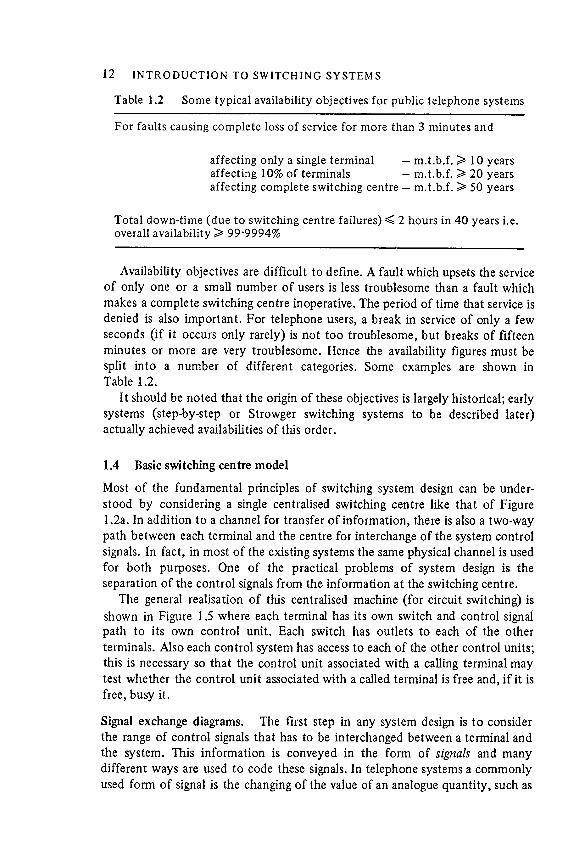
affecting only a single terminal - mit .b.f . ~ 10 yearsaffecting 10% of terminals - mit .b.f . ~ 20 yearsaffecting complete switching centre - mit .b.f . ~ SO years
Total down -time ( due to switching centre failures ) :::;;;: 2 hours in 40 years i .e.overall availability ~ 99 '9994 %
Availability objectives are difficult to define . A fault which upsets tile serviceof only one or a small number of users is less troublesome ilian a fault which
makes a complete switching centre inoperative . The period of time illat service is
denied is also important . For telephone users, a break in service of only a fewseconds ( if it occurs only rarely ) is not too troublesome , but breaks of fifteen
minutes or more are very troublesome . Hence tile availability figures must be
split into a number of different categories . Some examples are shown inTable 1.2 .
I t should be noted illat the origin of these objectives is largely historical ; early
systems (step -by -step or Strowger switching systems to be described later )actually achieved availabilities of this order .
1.4 Basic switching centre model
Most of the fundamental principles of switching system design can be understood by considering a single centralised switching centre like that of Figure
1.2a. In addition to a channel for transfer of information , there is also a two -way
paili between each terminal and the centre for interchange of the system control
signals . In fact , in most of the existing systems the same physical channel is used
for both purposes . One of the practical problems of system design is the
separation of the control signals from the information at the switching centre .
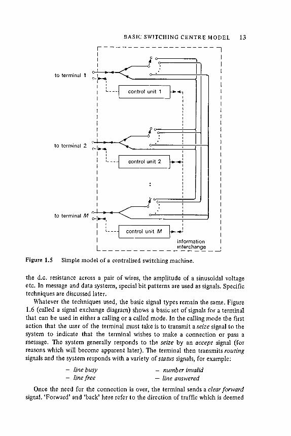
The general realisation of this centralised machine ( for circuit switching ) is
shown in Figure 1.5 where each terminal has its own switch and control signalpath to its own control unit . Each switch has outlets to each of the oilier
terminals . Also each control system has access to each of tile other control units ;
this is necessary so that the control unit associated with a calling terminal maytest wheilier the control unit associated with a called terminal is free and , if it is
free , busy it .
Signal exchange diagrams . The first step in any system design is to consider
the range of control signals that has to be interchanged between a terminal and
the system . This information is conveyed in the form of signals and many
different ways are used to code these signals . In telephone systems a commonly
used form of signal is tile changing of the value of an analogue quantity , such as
BASIC: SWITCHING CENTRE MODEL 13
1 - - - - - - - - - - - - - - - - - - - 1I
I 0 0 1 I
I .; 11 :~_ I....... I
I I I
I : f---~~~~;~~~I L - - - control unit 1 ~ ' , I
I I II
I I I
I : II : II : II : I
I . I I I. I
~ . . ~ I
(' - 1~ - 4 I i
I : : II :- - - J control unit 2 I ~ ~ II l "VII" V' UIII' L r - : II I I
I : II : : II : II I I
,
I . I I. I
. I I
to terminal M I . 1 I0- " " ' 1 1 I
I I I1 J " " ...+..,,1 " "' ;+ AA I ~ I I
I l__- ~ trol unit M 1 -04-' II information I
L - - - - - - - - - - - _ in::: r~h~ g-.: - -..:
to terminal 1
to terminal 2
Figure 1.5 Simple model of a centralised switching machine.
the d.c. resistance across a pair of wires, the amplitude of a sinusoidal voltageetc. In message and data systems, special bit patterns are used as signals. Specifictechniques are discussed later .
Whatever the techniques used, the basic signal types remain the same. Figure1.6 (called a signal exchange diagram) shows a basic set of signals for a terminalthat can be used in either a calling or a called mode. In the calling mode the firstaction that the user of the terminal must take is to transmit a seize signal to thesystem to indicate that the terminal wishes to make a connection or pass amessage. The system generally responds to the seize by an accept signal (forreasons which will become apparent later) . The terminal then transmits routingsignals and the system responds with a variety of status signals, for example:
- line busy - number invalid- line free - line answered
Once the need for the connection is over, the terminal sends a clear forwardsignal. ' Forward ' and 'back' here refer to the direction of traffic which is deemed

14 INTRODUCTION TO SWITCHING SYSTEMS
Figure 1.6 Basic signal exchange diagram.
concepts underlying an sit.d. can be explained by reference to thecontrol units in Figure 1.5. These control units may be thought of as existing ina number of stable states such as:
idle
waiting for routing information
waiting for answer
to flow from the originating terminal to the terminating terminal .
In the called mode the terminal is sent a seize signal from the system and
responds with an accept signal . At the end of the period of communication the
t ~ rm ! !1-~! ~ ~y ~ e sent a clear forward si W1al to indicate the end of the connection
.
In some systems a clear back signal is sent from the called terminal to the
system and possibly also from the system to the calling terminal if the user of the
called terminal is the first to indicate that the communication is finished . For
example , the signal sent from a telephone terminal to the local centre when the
handset is replaced at the end of a call is regarded as a clear forward signal if the
user initiated the call , but a clear back signal if the user was the recipient of the
call , even though the signals may take the same electrical form in practice .
State transition diagrams . The signal diagram gives the ' alphabet ' of the valid
signals between two devices . However , it does not indicate what sequences ( or
' sentences ' ) are possible or what they mean . The valid sequences and their
meaning can be expressed conveniently in what is called a state transition
diagrams .tid. ) . This is such a useful specification and design tool that a set of
international standards have been produced [ 6 ] for use in telecommunications
systems .
The
-
-
seize seize
accept accept
routing
terminal status switching terminal
(calling ) system (called )
clear forward clear forward
ctear backward ~ clear backward
In general a control unit moves from one state to another only because of thearrival of a signal from a tenninal or another control unit . The arrival of a signalis described as an event. When the unit does move from one state to another it
may perfonn some action such as operating a switch or sending a signal to
15BASIC SWITCHING CENTRE MODEL
connector(from other diagram)
state box
event name
event box
--
-
normal actionactionboxes
send signal
decision box
connectors
(a)
busy free invalid
(b)
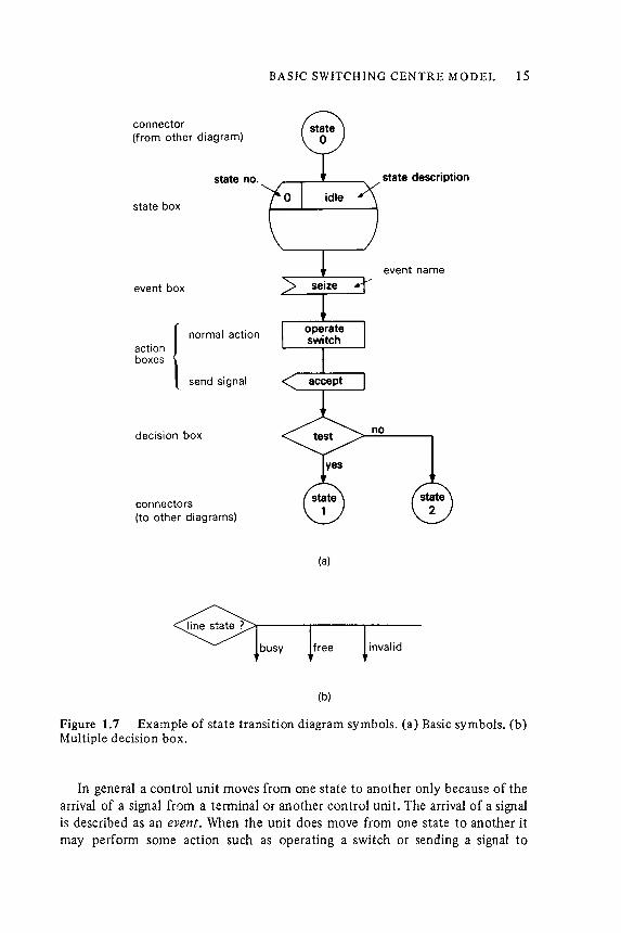
Figure 1.7 Example of state transition diagram symbols. (a) Basic symbols. (b)Multiple decision box .
(to other diagrams)
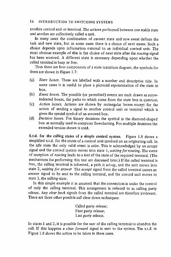
In states 1 and 2) it is possible for the user of the calling teffi1inal to abandon thecall. If this happens a clear forward signal is sent to the system. The sit .d. inFigure 1.8 shows the action to be taken in these cases.
S.tid . for the calling states of a simple control system. Figure 1.8 shows asimplified sit.d. for the states of a control unit involved on an originating call. Inthe idle state the only valid event is seize. This is acknowledged by an acceptsignal and the control system moves into state 1, waiting for routing . The eventof reception of routing leads to a test of the state of the required terminal . (Themechanisms for performing this test are discussed later .) If the called terminal isfree, the calling terminal is informed , a path is set-up, and the unit moves intostate 2, waiting for answer The accept signal from the called terminal causes ananswer signal to be sent to the calling terminal , and the control unit moves tostate 3, the talking state.
In this simple example it is assumed that the connection is under the control
of only the calling terminal . This arrangement is referred to as calling partyrelease. Any clear back signals from the called terminal are therefore irrelevant .There are three other possible call clear down techniques:
Called party release;First party release;Last party release.
16 INTRODUCTION TO SWITCHING SYSTEMS
another control unit or terminal . The actions performed between one stable stateand another are collectively called a task.
In many cases the combination of current state and new event defines thetask and new state, but in some cases there is a choice of next states. Such achoice depends upon information external to an individual control unit . The
most obvious example of this is the choice of next state after the routing signalhas been received. A different state is necessary depending upon whether thecalled tenninal is busy or free.
Thus there are four components of a state transition diagram, the symbols forth em are shown in Figure 1.7:
(a) State boxes. These are la belled with a number and descriptive title . Insome cases it is useful to place a pictorial representation of the state inbox .
(b) Event boxes. The possible (or permit ted) events are each drawn as arrow-
indented boxes, the paths to which come from the state box in question.(c) Action boxes. Actions are shown by rectangular boxes except for the
action of sending a signal to another control unit or tenninal which isgiven the special symbol of an arrowed box .
(d) Decision boxes. For binary decisions the symbol is the diamond-shapedbox as normally used in computer flowcharting . For multiple decisions theextended version shown is used.
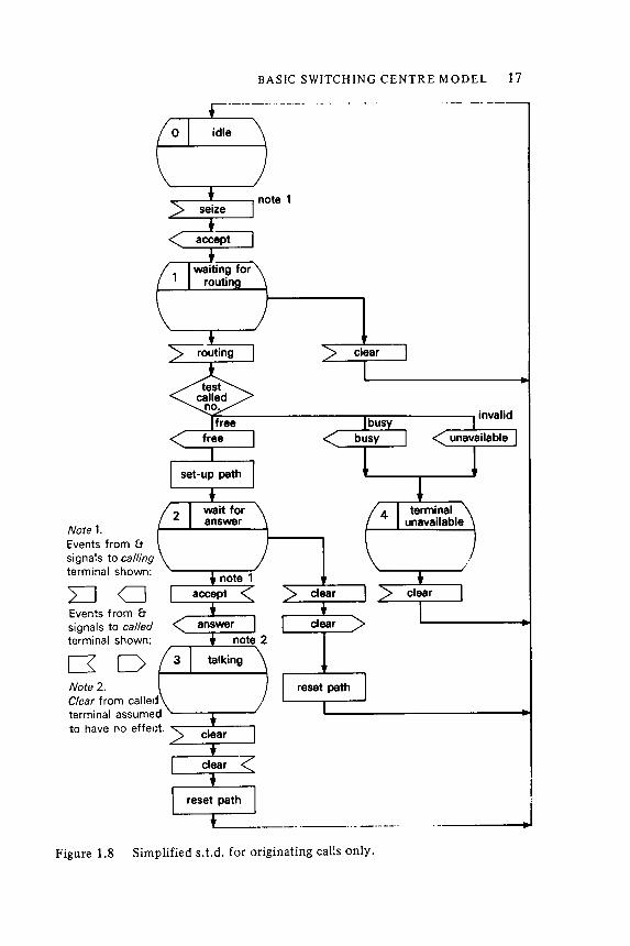
Figure 1.8 Simplified st .d. for originating calls only.
17BASIC SWITCHING CENTRE MODEL
Note 1 .
Events from &
signals to calling
terminal shown :
LJCJ
Events from &
signals to called
terminal shown :
[ 30
Note 2 .
Clear from callel
terminal assume
to have no effel
It can be made with very high system availability , because if it is properlydesigned, any fault in a control unit or its associated switch should affectat most , only two terminals, that is its own and anyone which happens tobe connected to it .
In the absence of faults, the only possible reason for an on-demandconnection to another terminal not being achieved is that the requiredterminal is already busy.
With present day technology , however, a system like this is generally un-economic. The art of switching systems' designers over the last century has beento find techniques to reduce the cost of a switching system, while maintaininghigh levels of system availability . Practical system designs take advantage of the
.
.
N
L
sw
control
18 INTRODUCTION TO SWITCHING SYSTEMS
The completes .tid . for originating and terminating calls are described inChapter 8.
two inherent
(a)
(b)
~
.
.
.
main
controlI Jnit
callingterminals
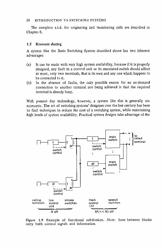
lines between blocksExample ofcontrol signals
M < N ) off
functional subdivision . Note :
and information .
Figure 1.9carry both
switchcontrol
\. - J
speech~witch~~
line access
control switch esunit
' - ~ J
N off
1.5 Resource sharing
A system like the Basic Switching System described above hasadvantages:
tocalledterminal
fa) Functional subdivision. It is not necessary for ali the functions of acontrol unit to be available all the time . For instance, while it is in the idle state
a control system for one terminal need only have the function of detecting aseize from its tem1inal or from another terminal that is its calling terminal . Also,when a tem1inal is in the conversation state its control system does not need the
functions involved in receiving and decoding the routings Ignals. The techniqueof functional subdivision involves partitioning a control unit into a number of
units , each of which provides only some of the functions of the completecontrol system. Each terminal needs a pem1anently associated unit to detectseize signals, but other units may be pooled and switching arrangements introduced
so that they are associated with a terminal only while they are needed.
This technique is shown in Figure 1.9 where the control unit has been partitioned into a line control unit and a main control unit . There is one line control
unit per terminal and these have access to a lesser number of main control units .
This technique can reduce the total amount of control equipment , but itintroduces the need for extra switching and its control . It also introduces thepossibility of a terminal having to wait for service if a common control unit isnot immediately available.
:
callingterminals
linecontrolunits
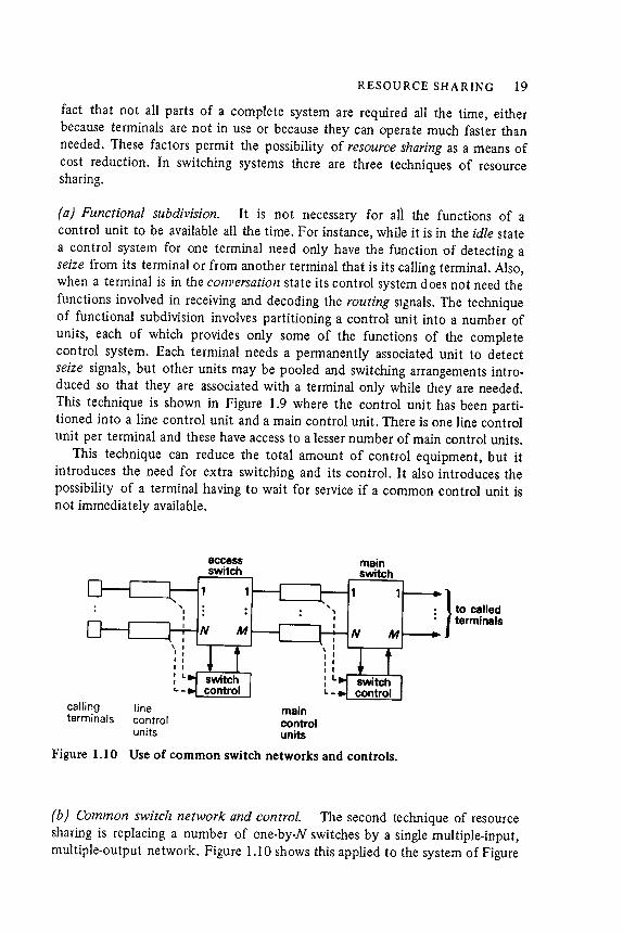
Figure 1.10
(b) Common switch network and control. The second technique of resourcesharing is replacing a number of one-by-N switch es by a single multiple-input,multiple-output network. Figure 1.10 shows this applied to the system of Figure
RESOURCE SHARING 19
fact that not all parts of a complete system are required all the time , eitherbecause tenninals are not in use or because they can operate much faster thanneeded. These factors permit the possibility of resource sharing as a means ofcost reduction . In switching systems there are three techniques of resourcesharing.
20 INTRODUCTION TO SWITCHING SYSTEMS
1 .9 , where the M one -by -N main switch es are replaced by a single M -by -N
network , and the N one -by - M access switch es are replaced by an N -by -M
network . It will be shown in Chapter 7 that this consider ably reduces the total
number of switch elements required in a system . There are two problems with
this technique :
( i ) In most designs of switch network there is a particular probability that no
path will be found between an inlet and outlet , even though the terminals
themselves are free .
( ii ) It is usually necessary to have a common control for the switch network ,
and if this goes wrong it will affect the complete system .
( c ) Time - Shared Decision Making . Each control system exists in a number of
states and changes its state only when some event occurs . When an event occurs
its control system must decide on the necessary actions and the new state . The
third method of resource sharing is possible because the time between occurrence
of events at a control system is much greater than the time required for making
decisions . For instance , in a telephone system the shortest time between events
for a single terminal is typically 30 ms or more , whereas electronic circuits can
make a decision in 1 . us or less . The decision - making component may therefore
be time -shared between a large number of control units of a given type . Each
unit needs a means of storing its current state , buffering the received event , and
storing the required actions .
The method by which these techniques of resource sharing are achieved are
discussed in Chapter 3 .
Objectives of System Design . All practical switching systems achieve their
economic objectives by different combinations of the above three techniques of
resource sharing . They all introduce the possibility that a resource , such as a
control unit , or a path through the network , may not be available when needed
by a terminal . When this occurs , the terminal must either abandon its call or wait
until the resource that it needs becomes available . A switching system must
provide sufficient resources so that the probability of a resource not being
available when it is needed , is kept below some design maximum . A significant
part of switching system design is therefore concerned with statistics .
I t will be seen later that the implementation of these three techniques
introduces system availability problems . The Basic Switching System can be the
basis of a highly reliable system structure , but when resource sharing is introduced
the possibility arises that a single fault may affect more than one terminal
and in some cases , the complete system . One aspect of the art of system design is
to develop techniques of resource sharing that minimise the effects of the faults
that will inevitably occur . Because a switching system must be economic , the
problem of system design is ultimately an economic one .
The problem of switching system design may be summarised as follows :
INTRODUCTION TO TRAFFIC AND QUEUEING THEORY 21
To develop the optimum level and arrangement of resource sharing whichsatisfies the functional requirements of the systems and keeps below a designobjective the probability of a terminal not being able to set-up a call due to
(a) lack of resource when needed, or(b) faults within a sub-system.
1.6 Introduction to traffic and queueing theory
The introduction of resource sharing into a telecommunications switchingsystem means that sometimes when a call request is made, the resources requiredwill not be immediately available. In these circumstances a call is said to beblocked . For some applications it is assumed that , if a call is blocked , the call isabandoned or ' lost ' . In other applications the call request is queued in some wayuntil the required resources become available, that is the call 'waits' or 'queues' .
In practice most systems have a mixture of call loss and call queueing. In atelephone system the caller must wait for dial tone but thereafter , if a requiredresource such as a trunk line is not immediately available, the call is lost and theuser receives a busy tone. Usually, even if the resource subsequently becomesavailable, the busy tone will not be removed.
Traffic theory and queueing theory are used to estimate the probability ofoccurrence of call blocking and, if queueing is involved, to estimate the statistical
distribution of the waiting times of blocked calls. In fact theory is usually
used for design rather than analysis, that is to estimate the quantity of resourcesrequired in order for a system to meet particular probabilities of loss andqueueing.
A theoretical analysis of the performance of a switching system needs twopieces of information as a starting point :
(a) a statistical description of the traffic demands from terminals, and(b) a set of performance objectives.
Traffic statistics. The traffic demands from terminals may be characterised by
the following :
fa) Calling rate. This is the average number of requests for connection that aremade per unit time . If the instant in time that a call request arises is a randomvariable, the calling rate may be stated as the probability that a call request willoccur in a certain short interval of time .
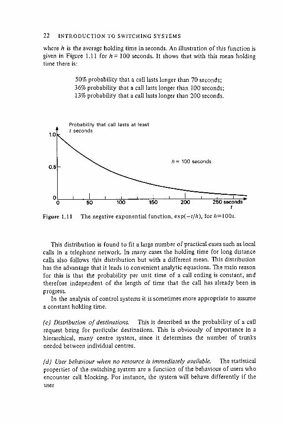
(b) Holding time. This may be characterised most simply by the mean timethat calls last. In some circumstances (particularly where there is call queueing)the statistical distribution of the holding times is also important . The mostcommonly used distribution is the negative exponential distribution in which theprobability of a call lasting at least t seconds is given by :
P(t) = exp(- tjh )
22 INTRODUCTION TO SWITCHING SYSTEMS
50% probability that a call lasts longer than 70 seconds;36% probability that a call lasts longer than 100 seconds;13% probability that a call lasts longer than 200 seconds.
Probability that call lasts at least
h = 100 seconds
Figure 1.11 The negative exponential function , exp(- tjh ), forh = I O Os.
This distribution is found to fit a large number of practical cases such as localcalls in a telephone network . In many cases the holding time for long distancecalls also follows this distribution but with a different mean. This distribution
has the advantage that it leads to convenient analytic equations. The main reasonfor this is that the probability per unit time of a call ending is constant, andtherefore independent of the length of time that the call has already been inprogress.
In the analysis of control systems it is sometimes more appropriate to assumea constant holding time.
(c) Distribution o[ destinations. This is described as the probability ofa callrequest being for particular destinations. This is obviously of importance in ahierarchical, many centre system, since it determines the number of trunksneeded between individual centres.
(d) User behaviour when no resource is immediately available. The statisticalproperties of the switching system are a function of the behaviour of users whoencounter call blocking . For instance, the system will behave differently if theuser
t seconds
where h is the average holding time in seconds. An illustration of this function isgiven in Figure 1.11 for h r= 100 seconds. It shows that with this mean holdingtime there is:
23
(a)(b)
The average number of concurrent calls.
INTRODUCTION TO T R Arl71 C AN D QU EUEING THEORY
- abandons the request ,
- makes repeated attempts to set up the call ,- waits until the resources become available .
Macroscopic traffic statistics: the erlang. As far as the switching elements of aswitching machine are concerned, it makes no difference whether a terminalmakes ten two -minute calls or one twenty -minute call . It will of course make a
difference to the control because to set up ten calls means more work . For this
reason studies of switching networks and their interconnecting trunks are normally made on the basis of total occupancy rather than the two parameters of
calling rate and holding time. The internationally agreed parameters used are asfollows [7] :
The amount of traffic carried (by a group of circuits or a group of switch es)during any period is the sum of the holding times expressed in hours.
The traffic flow (on a group of circuits or a group of switch es) equals theamount of traffic carried divided by the duration of the obser\fation , providedthat the period of observation and the holding times are expressed in the sameunits . Traffic flow calculated in this way is expressed in erlangs.
Thus the amount of traffic has the units of time and traffic flow is dimensionless
.
The erlang is named after A . K . Erlang, a mathematician who developed muchof the early theory of telephone traffic . Applying the definition to an individualterminal , if the average number of calls arising in time Tis n and the average
holding time of calls is h , the amount of traffic carried in time T = nh units oftime and the traffic flow A = nh/ T erlangs.
In the case of a single terminal the traffic in erlangs is equal to the averageoccupancy of the terminal , where occupancy i"s defined as the proportion of the
time that a terminal is busy. It can be easily shown that the traffic in erlangsfrom a group of terminals is numerically equal to both of the following :
The average number of calls which originate during the average holdingtime .
An alternative unit for traffic measurement in common use in North America
is the hundred call seconds (ccs) . This is used as a measure of the amount oftraffic expressed in units of 100 seconds. The number of ccs per hour is alsoused as a measure of traffic flow . Since 1 erlang may be regarded as an average ofone call for one hour , then:
1 erlang = 36 ccs h - 1
Busy hour traffic . The actual values of all parameters of traffic , and inparticular the calling rate, vary with time. In a telephone system the number of

- an outgoing call to the trunk network,
24 INTRODUCTION TO SWITCHING SYSTEMS
calls made per hour varies throughout the day. For instance, there is a peak inthe calling rate in the morning for a telephone system with mainly businessusers. For a system in a largely residential area the peak may occur in the earlyevenings. Although the evening peak may be partly due to the operation of a'cheap rate' tariff , the morning peak is largely due to the habits of business usersand is affected only temporarily by the introduction of rugher 'peak rate' tariffs .So, cheap rate tariffs may be said to stimulate use of the telephone whereas peakrate tariffs are simply a way of maximising revenue in an acceptable way. Forlong distance traffic the peaks for different parts of the network may occur atdifferent times due to time-zone differences. Other significant traffic patternsmay arise from regular commercial events, for example traffic peaks betweenfishing ports and London may follow the tides because the fish market followsthe landing of the catch.
In addition to changes within the day, the calling rate may vary with theseason of the year, for instance it may be rugher during the summer season in aholiday resort. There are very large peaks at holiday times such as Christmas, or,in the U.S.A ., Mothers' Day. Most switcrung systems grow with time, in terms ofthe number of terminals, so the total traffic increases. It is interesting to notethat , as a system such as the telephone system grows, there is a tendency forcalling rates (per terminal ) to decrease during certain stages of this growth ,presumably because an increased number of terminals means fewer peoplesharing each terminal . At other stages, this effect is outweighed by increased useper person, due to the increasing number of easily contractable correspondents.
In order to design ~ suitable switcrung system some traffic figures are neededwhich represent the average demands made by users on the system over aplanning period of the order of six months. In the telephone field , the so-calledbusy hour traffic figures are used for planning purposes. An hour is chosenbecause it is long compared with the average holding time of around 3 minutes.If the parameters are measured for the busiest hour on a number of the busiestdays of the year, the mean of these measurements gives a useful measure of thetraffic .
Once the statistical properties of the traffic from or to a set of terminals areknown , it is necessary to state an opjective for the performance of a switchingsystem. This is done by specifying a grade of service (g.o.s.). For a systemdesigned on a loss basis, a suitable grade of service is the percentage of callswhich are lost because no equipment is available at the instant of the callrequest. In a waiting system a grade of service objective could be either thepercentage of calls which are delayed or the percentage which are delayed morethan a certain length of time .
This grade of service is applied to a terminal -to-tenninal connection , but in asystem containing many switching centres it is usually more convenient to breakthe objectives down into component parts such as the grades of service for :
- an internal call,

25INTRODUCTION TO TRAFFIC AND QUEUEING TIIEORY
- the trunk network itself ,
- a terminating call .
The reasons behind the choice of objectives are not clear cut . They must be a
balance between economics and user satisfaction . The economics can be
computed , but the user ' s satisfaction cannot . One objective approach for a
commercial system is to find the grade of service for which the cost of adding
the extra equipment is equal to the revenue that is being lost by calls being lost
[ 8 ] . Although easy to state , this computation is difficult to perform and often
gives results which , although ' economic ' , are unacceptable to the user . For
instance , if the grade of service for a long distance route is greater than 10 % the
user will experience considerable annoyance .
Typical objectives for overall grades of service for a commercial telephone
system are 3 - 5 % for local calls and ( because the cost of equipment provision is
higher ) up to 6 or 7 % for long distance calls . These figures are comparable with
the probability that the called user is already busy .
Typical objectives for component parts of a connection are :
Internal Calls 3 % Trunk Calls 1 - 3 %
Outgoing Calls 2 % Incoming Calls 2 %
For the above , the overall grade of service is in fact approximately the sum of
the component grades of service .
However , this is not a complete specification because it relates only the
grades of service for a mean busy hour . In order to ensure that the grade of
service does not deteriorate disastrously if the actual busy hour traffic exceeds
the mean ( or if some of the equipment is out of service ) , additional grades of
service are specified relating to traffic loads of 10 % or 20 % above the mean , or
with certain percentages of the system not operational .
Traffic design objectives . Traffic design objectives for a switching system are
generally expressed in terms of a set of traffic flows to be carried by the system
with a performance no worse than a set of grades of service for the different
types of traffic . In addition , the performance of the system must not deteriorate
beyond a certain set of grades of service under specified overload or fault
conditions , such as 10 % overload or only 90 % of the equipment being available
because of faults .
The grades of service that are relevant for a message switching system relate
to delay . All communications are delayed to a certain extent so a system might
have an objective of the form : 99 % probability of delivering a message within 24
hours of transmission . This may be too slow for certain types of message , so a
range of message priorities is normally used to allow the more urgent messages to
' jump ' the queue and be delivered ahead of previously transmitted , lower
26 INTRODUCTION TO SWITCHING SYSTEMS
priority messages . The existence of these levels of priorities complicates the
analysis .
A data system may be either circuit switched or packet switched . In a circuit
switched system conventional loss probabilities may be used . The critical factor
in a packet switching system is usually response time , for example the time
taken for a packet to travel from one terminal to a main computer , for that
packet to be processed , and for response to be returned to the originating
terminal . If there is a human user , acceptable performance standards are typically
a mean response time of 1 ' 5 seconds and 90 % of responses obtained within
3 seconas [ 91 .
References
1 . Hills , M . T . and Evans , B . G . ( 1973 ) Telecommunications Systems . Allen & Unwin .
2 . Beck , I . H . ( 1972 ) Mobile radio systems , Post Office Elect . Eng . J . , 64 , p . 238 .
3 . Rapp . Y . ( 1950 ) The economic optimum in urban telephone network problems . Ericsson
Technics , 49 .
4 . f ' - or example , see Back , RE . G . ( 1975 ) Network planning , in Telecommunications
Networks . J . E . I ;' lood , ed . , Peter Peregrinus .
5 . CCITT ( 1964 ) National Telephone Networks j ' or Automatic Service . ITU .
6 . C C I T T Orange Book ( 1977 ) Vol . VI , Recommendation l101 .
7 . CCITT Orange Book ( 1977 ) Vol . II , Recommendation 160 .
8 . Jenson , A . ( 1950 ) Moes Principle . An t ," conomic Investigation Intended as an Aid in
Dimensioning and Managing Telephone Plant . Copenhagen Telephone Company .
9 . Martin J . ( 1972 ) Systems Analysis for Data Transmission ( Chapter 7 ) . Prentice Halt .