1. interference of light fresnel’s bi –...
TRANSCRIPT

1
Department of Physics
R.B.V.R.R WMOEN’S COLLEGE (AUTONOMOUS) Name:
Roll No:
Date:
1. Interference of Light – Fresnel’s Bi – prism
Aim : To determine the wave length of sodium light with Fresnel’s Bi- Prism by forming
interference fringes.
Apparatus : Optical bench with up rights, sodium lamp, Bi – prism, convex lens, slit and
micrometer eye piece.
Theory : Bi prism is a prism with a large obtuse angle (nearly 179°) which acts as two narrow
angle (1/2o) prisms placed base to base. It produces two virtual images of a single object, close to
each other on either sides of the object. The two virtual sources S1 and S2 produced by the Bi
prism are coherent and produce interference fringes parallel to the source.
The band width of the fringes is given by β = Dλ
d
or fringe width is the distance between two consecutive bright fringes or two consecutive dark
fringes.
Where, D is the distance between the slit and eye piece.
d is the distance between the two virtual images.
λ is the wave length of light used.
To avoid index error fringe width β1 and β2 are measured at two different distances
D1 and D2.
. . λ = (β2 - β1) d
(D2 - D1)
Distance between the two virtual sources d = √d1d2.
Where d1 = is the distance between the two diminished images of the virtual sources.
d2 = is the distance between the two magnified images of the virtual sources.
Fig.

2
Department of Physics
R.B.V.R.R WMOEN’S COLLEGE (AUTONOMOUS) Name:
Roll No:
Description :
The optical bench used in the experiment consists of a heavy cast iron base supported by four
levelling screws. There is a graduated scale along its own arm. The bench is provided with four
uprights which can be clamped any where and the position can be read by means of vernier
attached to it. Each of the uprights is subjected to the following motions :
(i) motion along bench
(ii) transverse motion (motion right angle to bench)
(iii) Rotation about the axis of the upright.
With the help of a tangent screw, the slit and Bi – prism can be rotated in their own vertical
planes.
Action of Bi-prism : As shown in above fig. monochromatic light from a source S falls on two
points of the prism and is bent towards the base. Due to the division of wave front, the refracted
light appears to come from S1 and S2. The waves from two sources unite and give interference
pattern. The fringes are hyperbolic, but due to high eccentricity they appear to be straight lines in
the focal plane of eye piece.
Procedure :
Adjustments:
(1) The slit Bi-prism and eye piece are adjusted at the same height and the slit and the cross
wire of eye piece are made vertical.
(2) The micrometer eye piece is focused on cross wires.
(3) With an opening provided to the cover of the monochromatic source, the light is allowed
to be incident on the slit and the bench is so adjusted that light comes straight along its
lengths. This adjustment is made to avoid the loss of light intensity for the interference
pattern.
(4) Place the Bi-prism upright near the slit and move the eye piece side ways. See the two
images of the slit through Bi-prism, if they are not seen, move the upright of Bi-prism
right angle to the bench till they are obtained. Make the two images parallel by rotating
Bi-prism in its own plane.
(5) Bring the eye piece near to the Bi-prism and give it a rotation at right angle of the bench
to obtain a patch of light. As a matter of fact, the interference fringes are obtained in this
patch provided that the edge of the prism is parallel to the slit.
(6) To make the edge of the Bi-prism parallel to the slit, the Bi-prism is rotated with the help
of tangent screw till a clear interference pattern is obtained. These fringes can be seen
with the naked eyes.

3
Department of Physics
R.B.V.R.R WMOEN’S COLLEGE (AUTONOMOUS) Name:
Roll No:
Measurement of fringe width β:
(1) Find out the least count of the micrometer.
(2) Place the micrometer screw at such a distance where fringes are distinct, bright and
widely spaced.
(3) The cross wire is moved on one (Right – Left) side of the fringes to avoid backlash error.
Now the cross wire is fixed at the centre of a dark fringe ‘m’ and its reading is noted on
the main scale as well as micrometer screw.
(4) The cross wire is now moved and fixed at the centre of fifth dark i.e. m+5 fringe. The
micrometer readings are noted. In the same way focus the cross wire on the next 5th dark
ring i.e. m+10, m+15, m+20 etc each time. Note the micrometer reading. From these
observations β1 can be calculated at D1 distance. (Distance between slit and eye piece)
(5) Repeat the experiment at D2 distance and calculate β2.
Measurement of d :
(1) To obtain the value of d, the position of slit and Bi-prism uprights are not disturbed.
(2) A convex lens is introduced between Bi-prism and eye piece and moved in between to
obtain two sharp and focused images (magnified images) of the virtual source. The
distance between two images is noted. This distance is denoted by d1.
(3) The lens is again moved towards eye piece to obtain the second position where again two
sharp and focused images are obtained. (diminished images) The distance in this case
denoted by d2.
Knowing d1 and d2, d can be calculated by using the formula d = √d1d2.
Precautions :
(1) The setting of the uprights at the same level is essential.
(2) The slit should be vertical and narrow.
(3) Cross wire should be fixed in the centre of the fringe while taking observations for fringe
width.
(4) The micrometer screw should be rotated only in one direction to avoid backlash error.
(5) Convex lens of shorter focal length should be used (f = 10 cm. approximately).
Result :
Lecturer signature with Date:
4
Department of Physics
R.B.V.R.R WMOEN’S COLLEGE (AUTONOMOUS) Name:
Roll No:
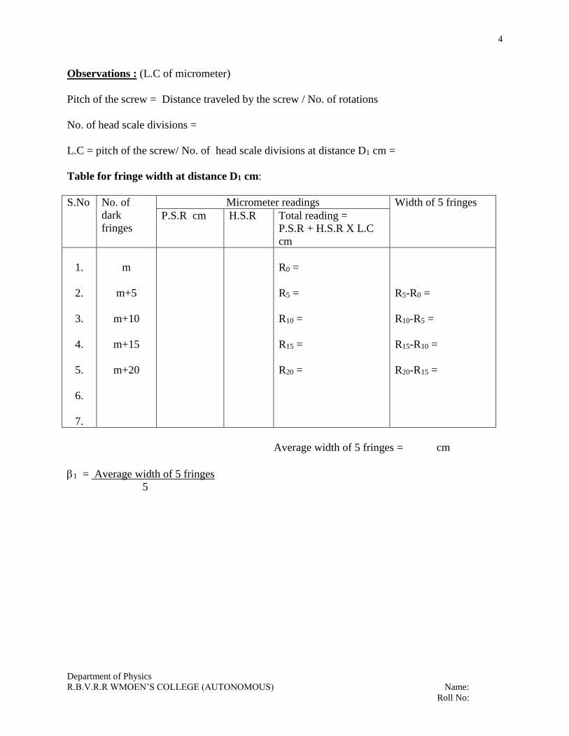
Observations : (L.C of micrometer)
Pitch of the screw = Distance traveled by the screw / No. of rotations
No. of head scale divisions =
L.C = pitch of the screw/ No. of head scale divisions at distance D1 cm =
Table for fringe width at distance D1 cm:
S.No No. of
dark
fringes
Micrometer readings Width of 5 fringes
P.S.R cm H.S.R Total reading =
P.S.R + H.S.R X L.C
cm
1.
2.
3.
4.
5.
6.
7.
m
m+5
m+10
m+15
m+20
R0 =
R5 =
R10 =
R15 =
R20 =
R5-R0 =
R10-R5 =
R15-R10 =
R20-R15 =
Average width of 5 fringes = cm
1 = Average width of 5 fringes
5

5
Department of Physics
R.B.V.R.R WMOEN’S COLLEGE (AUTONOMOUS) Name:
Roll No:
B. Fringe width at distance D2 = cm
S.No No. of
dark
fringes
Micrometer readings Width of 5 fringes
P.S.R cm H.S.R Total readings =
P.S.R + H.S.R X L.C
cm
1.
2.
3.
4.
5.
6.
7.
m
m+5
m+10
m+15
m+20
R0 =
R5 =
R10 =
R15 =
R20 =
R5-R0 =
R10-R5 =
R15-R10 =
R20-R15 =
Average width of 5 fringes =
2 = Average width of 5 fringes
C. Table for distance between the two coherent virtual sources S1 and S2 is d
Nature of
the Image
Reading of the micrometer screw when the vertical cross wire coincides with
the image
Distance
between the
two images
a-b cm First image S1 Second image S2
Magnified
diminished
P.S.R
cm
H.S.R P.S.R+H.S.RXL.C
a cm
P.S.R
cm
H.S.R P.S.R+H.S.RXL.C
b cm
Magnified
diminished
d1=
d2=
Distance between S1 and S2 = d = d1d2 cm

6
Department of Physics
R.B.V.R.R WMOEN’S COLLEGE (AUTONOMOUS) Name:
Roll No:
Date:
2. Thermal conductivity of a bad conductor
(Lees Method)
Aim: To determine the coefficient of thermal conductivity (K) of a bad conductor by Lees
method.
Apparatus: The Lees apparatus, given bad conductor, two thermometers, stop watch, screw
gauge, vernier calipers, a rough balance.
Theory :
(1) Heat conducted per second by the bad conductor at steady state = Kπr²(θ1-θ2)
d
Where, r = radius of the bad conductor.
d = thickness of the bad conductor.
Θ1 = steady state temperature of the steam chamber.
Θ2 = steady state temperature of the brass disc.
K = coefficient of thermal conductivity of the bad conductor
(2) Heat radiated per second by the brass = ms. dθ
dt
Surface area of the disc radiating heat = 2πr² + 2πrh.
Where, m = mass of the brass disc.
s = specific heat of the brass disc. = 0.089 cal/gm.
r = radius of the brass disc = cm.
h = thickness of the brass disc = cm.
dθ = rate of cooling at steady state temperature Θ2
dt
(3) At steady state the heat conducted per second by the bad conductor is equal to the heat
radiated per second by the brass disc.
Surface area of the disc radiating heat at steady state = πr²+2πrh
Hence heat radiated by the brass disc at steady state = ms dθ (r+2h) dt 2(r+h)
Kπr²(θ1-θ2) = ms dθ (r+2h) d dt 2(r+h)
K = ms d r+2h d . Joules/sec/unit area/unit temperature gradient
dt 2(r+h) r2 (1-2)
Description: The Lees apparatus consists of a nickel coated brass disc suspended with its plane
horizontal by means of three stings tied to the ring of a retort stand. On the brass disc, the given
bad conductor in the form of a thin disc of the same diameter as the brass disc is placed. And
upon the bad conductor a brass steam chamber is placed and having the diameter as that of the
bad conductor. The steam chamber is provided with an inlet and outlet for the passage of steam.

7
Department of Physics
R.B.V.R.R WMOEN’S COLLEGE (AUTONOMOUS) Name:
Roll No:
Fig.
Procedure:
(1) The mass ‘m’ of the lower brass disc is found with a rough balance. The mean thickness
d and the mean radius r of the lower brass disc are determined with a vernier calipers.
The mean thickness t of the bad conductor is determined with the screw gauge.
(2) The bad conductor is placed in its proper position between the lower brass disc and the
steam chamber. Steam is passed for a sufficiently long time until a steady temperatures of
Θ1° and Θ2° c reached by the steam chamber and the brass disc respectively. In this
steady state, heat is conducted across the bad conductor and received by the lower disc.
The heat gained by conduction per second by the brass disc is equal to the heat last by it
per second due to radiation.
(3) The bad conductor is removed and lower disc is directly put in contact with the steam
chamber. The brass disc is heated until its temperature rises by about 5°c above its steady
temperature Θ20 c. The steam chamber is removed and the brass disc is allowed to cool.
As the brass disc cools, its temperature is noted at half a minute until the temperature of
the disc cools 5°c below the steady temperature θ2° c.
Graph : A cooling curve is drawn showing the
time intervals in minutes on the X-axis and the
corresponding temperature on the Y-axis. From
the graph the time taken ‘t’ minutes for the
temperature to fall from (θ2+1)°c to (θ2 -1)°c is
noted. Then the rate of cooling at the steady
temperature θ2 c is found by
α = 2/60χt °c/sec.

8
Department of Physics
R.B.V.R.R WMOEN’S COLLEGE (AUTONOMOUS) Name:
Roll No:
Precautions :
(1) The thickness of the bad conductor should be taken at least in three different places.
(2) Steam is passed for a sufficiently long time until there is no further increase of the
temperature θ2 c. Result :
Lecturer signature with Date:

9
Department of Physics
R.B.V.R.R WMOEN’S COLLEGE (AUTONOMOUS) Name:
Roll No:
Observations :
Mass of the brass disc (m) = gm.
Mean thickness of the lower disc (h) = cm.
Mean radius of the lower disc ( r )= cm.
Mean thickness of the bad conductor(d) = cm.
Steady temperature of steam chamber θ1 = °c
Steady temperature of the lower disc θ2 = °c
Specific heat of the lower disc (s) =
Rate of cooling from graph = dθ = 2 = °c/sec.
dt 60χt
S.No. Time ( t ) Temperature θ20 c
1
2
3
4
5
6
7
8
9
10
11
12
0
½
1
1 ½
2
2 ½
3
3 ½
4
4 ½
5
5 ½

10
Department of Physics
R.B.V.R.R WMOEN’S COLLEGE (AUTONOMOUS) Name:
Roll No:
Date:
3. Verification of Law of Malus
Aim: To verify the Law of Malus for Intensity of polarized light.
Apparatus: Polarizer, Analyzer, source of light, solar cell and digital multimeter or voltmeter.
Principle :According to Malus, when completely plane polarized light is incident on the analyzer, the intensity I of
the light transmitted by the analyzer is directly proportional to the square of the cosine of the angle between
transmission axes of the analyzer and the polarizer.
i.e. I Cos2θ
Suppose the angle between the transmission axes of the analyzer and the polarizer is θ. The completely plane
polarized light from the polarizer is incident on analyzer. If EO is amplitude of the electric vector transmitted by the
polarizer, then intensity IO of the light incident on the analyzer is I EO2 (from the theory of light waves)
The electric field vector EO can be resolved into two rectangular components i.e. EO Cos θ and EO Sin θ. The
analyzer will transmit only the components(i.e. EO Cos θ ). Which is parallel to the transmission axis. However, the
component EO Sin θ will be absorbed by the analyzer .
Therefore, the intensity I of light transmitted by the analyzer is
I (EO Cosθ )2
I (EO Cosθ )2
---- = -------------- = Cos2θ
IO EO2
I = IO Cos2 θ
I Cos2 θ
This proves Law of Malus.
When θ = 0O or 180O, I = IO Cos2 θ = IO , That is the intensity of light transmitted by the analyzer is maximum when
the transmission axes of the analyzer and the polarizer are parallel.
When θ = 90O, I = IO Cos2 90O = 0. That is the intensity of light transmitted by the analyzer is minimum when the
transmission axes of the analyzer and the polarizer are perpendicular to each other.
Description:
The apparatus consists of a long hollow tube of about 1 ½ inches in diameter and 10 inches in length. The polarizer
and analyzer are fixed at the two ends of the tube. Polarizer is rotatable on the graduated scale and analyzer is fixed.
A solar cell is fixed at he analyzer side. By using a digital multimeter the voltage developed across the cell is
measured.

11
Department of Physics
R.B.V.R.R WMOEN’S COLLEGE (AUTONOMOUS) Name:
Roll No:
Circuit Diagram
Procedure:
1. Arrange the apparatus as shown in fig.
2. The beam of light from the source is incident on the polarizer. The light gets polarized. This polarized light
passes through the analyzer.
3. Fix the angle between the optic axis of polarizer and of analyzer to 0O. Now measure the voltage across the
cell using a digital multimeter.
4. Repeat the same procedure by changing angle in steps of and measure the corresponding voltage on the cell
till the angle reaches 360O
5. Note the observations in the given table
6. Now draw a graph between θ on x – axis and Intensity (i.e. voltage across the cell) on y-axis.
7. Repeat the experiment for two intensities.
Graph:
Note: A SOLAR CELL is used to measure the intensity of the polarized light emerging from the analyzer.
Construction: A solar cell consists of P-N junction diode made of silicon. The inward arrow in the symbol indicates
the incoming light. The P-N diode is packed in a can with glass window on top so that light may fall upon P and N
type materials. The thickness of the P-region is kept very small so that electrons generated in this region can diffuse
to the junction before recombination takes place. Thickness of N-region is also kept small to allow holes generated
near the surface to diffuse to the junction before they recombine. A heavy doping of P and N regions is done t obtain
a large photo voltage. A nickel plated ring is provided around the P-layer. This acts as the positive output terminal.
A metal contact at the bottom serves as the negative output terminal.
Working:

12
Department of Physics
R.B.V.R.R WMOEN’S COLLEGE (AUTONOMOUS) Name:
Roll No:
When light radiation falls on a P-N junction diode, photons collide with valence electrons and impart them
sufficient energy enabling them to leave their parent atoms. Thus electron hole pairs are generated in both the P and
N sides of the junction. These electrons and holes reach the depletion by diffusion and are then separated by the
strong barrier field existing there.
There are some minority carriers in both P and N regions which reach the opposite side in spite of the
barrier potential.
Their flow constitutes the minority current which is directly proportional to the illumination and also
depends on the surface area being exposed to light.
The accumulation of electrons and holes on the two sides of the junction gives rise to an open circuit
voltage Voc which is a function of illumination. The open-circuit voltage produced for a silicon solar cell is typically
0.6Volt and the short circuit current is about 40mA/cm2 in bright light.
When polarized light from the analyzer is incident on the solar cell a potential drop or voltage is developed across
the ends.. This voltage is proportional to the intensity of the light.
V I Cos2θ
So by drawing a graph between V and θ we can verify the Malus law.
Precautions:
1) Fix the angle between optic axis of polarizer and analyzer with out any parallax error.
2) Ensure that the when θ = 0O and 180O i.e. for max intensity max voltage is observed and when θ = 90O and
θ = 270O i.e. for minimum intensity minimum voltage is observed)
Result :
Lecturer signature with date:

13
Department of Physics
R.B.V.R.R WMOEN’S COLLEGE (AUTONOMOUS) Name:
Roll No:
Observation:
S.No Angle between optic axis of polarizer and of analyzer(θ) Cos2θ Voltage on the cell (V)
0 O
30 O
60 O
90 O
120 O
135 O
150 O
180 O
210 O
225 O
240 O
270 O
330 O
345 O
360O

14
Department of Physics
R.B.V.R.R WMOEN’S COLLEGE (AUTONOMOUS) Name:
Roll No:
Date:
4. SPECIFIC ROTATORY POWER
POLARI METER
Aim: To determine the specific rotatory power of an optically active substance like cane – sugar
solution using polarimeter.
Apparatus: Polarimeter, mercury lamp, distilled water, measuring jar, balance, beaker and a
weight box.
Theory: Optically active substances like cane sugar solution, turpentine and quartz possess the
property of rotating the plane of polarization of plane polarized light.
The angle of rotation ‘θ’ depends upon
(i) The length l of the active substance
(ii) The concentration ‘c’ of the solution
(iii) Wave length λ of light
(iv) The temperature of the solution.
Specific rotatory power at a given temperature and for a given wave length is defined as the
rotation in degrees produced by a path of one decimeter length in a substance of unit density.
S = 10 θ
ℓ c
Fig.

15
Department of Physics
R.B.V.R.R WMOEN’S COLLEGE (AUTONOMOUS) Name:
Roll No:
Description: It is an instrument used for measuring the optical rotation of certain substances.
The essential part of Laurent’s bi – quartz polarimeter is shown in the above figure.
The polarimeter consists of two crossed Nicol prisms viz., the polarizer and the
analyzer, which are arranged coaxially. The optically active substance (say, sugar solution)
whose specific rotatory power is to be determined is filled in glass tube G, of length 1 cm. which
is placed between the polarizer and analyzer. The ends of the glass tube G are closed by the
metal caps which consist of windows or optically plane glass plates. The optically active
substance rotates the plane of polarization of the light traversing through it. By means of the
analyzer, the angle of rotation of the plane of polarization can be measured. A half-shade device
is interposed between the polarizer and the glass tube G.
‘S’ is a source of white light (mercury lamp) placed at the focus of a convex lens.
Light from the source is rendered parallel by means of convex lens and incident on the polarizer.
The parallel beam of light after passing through the polarizer emerges out as a plane polarized,
light which illuminates the bi-quartz. The polarized light passes through the bi-quartz device and
then traverses through the polarimeter tube G, containing the optically active solution. The light
emerging from the polarimeter tube G (containing the optically active solution) can be analyzed
by means of the analyzer. The emergent light from the analyzer can be observed through a
telescope. The convex lens L, polarizer, the bi-quartz, the analyzer and the telescope all are
enclosed in a detachable single tube.
Bi-Quartz: It is a device that is used to increase the sensitiveness of the pair of Nicols in
experiments on the rotation of plane of polarization.
A bi-quartz consists of two semicircular plates of quartz cemented together to form a
disc. Each of the plates is cut perpendicular to the optic axis. One piece is from right handed
quartz and the other from left handed quartz. The thickness is so adjusted that it causes a rotation
of 90 for sodium light yellow with λ=5893A
When plane polarized white light is normally incident on bi-quartz, rotatory dispersion occurs in
each plate, the plane of vibration in the two halves being rotated in opposite directions.

16
Department of Physics
R.B.V.R.R WMOEN’S COLLEGE (AUTONOMOUS) Name:
Roll No:
The plane of vibration of yellow light is rotated through 90. For red this rotation is least and for
violet it is greatest. The above figure represents that the vibration plane of the incident light,
coincides with N1N1 and AR. AO AY AG and AV represents the vibration plane for red,
orange, yellow, green and violet on emergence from bi-quartz.
If the bi-quartz is now viewed through the analyzing nicol set with its principal section N2N2,
parallel to N1N1 then since YY is one straight line, the yellow line λ=5893 A
Will be simultaneously quenched from both halves of the field of view. Thus in this setting
yellow colour will be absent from each portion and the residual. Colour in these portions is due
to a combination of the transmitted components of the different colours, predominantly violet
and red presenting a grey appearance of the field of view. This colour is called limit of passage
and represents the correct setting of the analyzer. This is quite sensitive position.
If now the analyzer is given a slight rotation in clockwise direction, it increases the proportion of
red in the right hand half and of violet in the left hand half portion of the field of view. Hence
this slight clockwise rotation of the analyzer suddenly changes the colour from grey to pink in
the right hand half and from grey to blue in the left hand half portion. A rotation in anticlockwise
direction reverses this colour scheme.
Note that if we put the analyzer with its principal section parallel to YY line, then for each colour
two halves will have equal intensities for all colours. A clockwise rotation of analyzer increases
violet in the right half but increases red in the left half. But this will not be a sharp change.
To measure the angle of rotation:
The polarimeter tube is filled with distilled water and placed between the analyzer and polarizer.
The analyzer is set in the position of tint of passage and reading of its position is taken on the
circular scale. Next the optically active substance is put between the bi-quartz and the analyzer.
The analyzer is again set in the position of tint of passage and its position is again read on the
circulate scale. The difference between the two readings gives the angle of rotation of the plane
of polarization.
The distinctive advantage of the bi-quartz device lies is the fact that while light can be used with
it and still the measurements are for yellow light λ=5893A only.
Action of the bi-quartz plate: Each half portion of the bi-quartz circular plate produces equal
rotation of the light incident normally upon them but in opposite directions. This device is placed
just behind the polarizing Nicol. If the incident light is white, the different colours will be rotated
through different angles and the emergent light passes through the analyzing Nicol. Waves of
different refractibilities will be obstructed in the two halves and the two semicircles will appear
of two different colours. If, however the principal planes of polarizing and analyzing Nicols are
parallel, the light of the same colour will be extinguished in both the halves and other colours
will be present in same proportion. The two parts will thus appear grey-violet coloured. This
colour is named as the tint of a passage or sensitive tint. If the analyzer is now rotated through a
very small angle, one of the quartz piece becomes pink and other blue. This shows that a marked
change is brought about in the appearance of the bi-quartz plate on slight rotation of the analyzer.
17
Department of Physics
R.B.V.R.R WMOEN’S COLLEGE (AUTONOMOUS) Name:
Roll No:
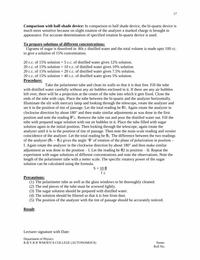
Comparison with half-shade device: In comparison to half shade device, the bi-quartz device is
much more sensitive because on slight rotation of the analyzer a marked charge is brought in
appearance. For accurate determination of specified rotation bi-quartz device is used.
To prepare solutions of different concentrations:
15grams of sugar is dissolved in 80c.c distilled water and the total volume is made upto 100 cc.
to give a solution of 15% concentration.
20 c.c. of 15% solution + 5 c.c. of distilled water gives 12% solution.
20 c.c. of 15% solution + 10 c.c. of distilled water gives 10% solution.
20 c.c. of 15% solution + 20 c.c. of distilled water gives 7.5% solution.
20 c.c. of 15% solution + 40 c.c. of distilled water gives 5% solution.
Procedure:
Take the polarimeter tube and clean its walls so that it is dust free. Fill the tube
with distilled water carefully without any air bubbles enclosed in it. If there are any air bubbles
left over, there will be a projection at the centre of the tube into which it gets fixed. Close the
ends of the tube with caps. Place the tube between the bi-quartz and the analyzer horizontally.
Illuminate the slit with mercury lamp and looking through the telescope, rotate the analyzer and
set it in the position of tint of passage. Let the total reading be θ1. Again rotate the analyzer in
clockwise direction by about 180° and then make similar adjustments as was done in the first
position and note the reading θ11. Remove the tube out and pour the distilled water out. Fill the
tube with prepared sugar solution with out air bubbles in it. Place the tube filled with sugar
solution again in the initial position. Then looking through the telescope, again rotate the
analyzer until it is in the position of tint of passage. Then note the main scale reading and vernier
coincidence of the analyzer. Let the total reading be θ2. The difference between the two readings
of the analyzer (θ1 ~ θ2) gives the angle ‘θ’ of rotation of the plane of polarization in position –
I. Again rotate the analyzer in the clockwise direction by about 180° and then make similar
adjustment as was done in the position – I. Let the reading be θ2 in position – II. Repeat the
experiment with sugar solutions of different concentrations and note the observations. Note the
length of the polarimeter tube with a meter scale. The specific rotatory power of the sugar
solution can be calculated using the formula.
S = 10 θ
ℓ c
Precautions:
(1) The polarimeter tube as well as the glass windows to be thoroughly cleaned.
(2) The end pieces of the tube must be screwed lightly.
(3) The sugar solution should be prepared with distilled water.
(4) The solution should be filtered so that it is free from dust.
(5) The position of the analyzer with the tint of passage should be accurately noticed.
Result:
Lecturer signature with Date:

18
Department of Physics
R.B.V.R.R WMOEN’S COLLEGE (AUTONOMOUS) Name:
Roll No:
Observations:
(1) Length of the polarimeter tube ‘l’ = cm.
(2) Least count of the circular scale =
(3) Reading of the circular scale of the analyzer when there is tint of passage with
distilled water in the tube.
Position – I Position - II
Θ1 = Θ11 =
Average value of S = degree/dm/gm/c.c.
S.No.
Concentration
C
gm/c.c
Reading with sugar
solution θ2
Angle of rotation
Θ = θ1~ θ2 Mean
θ
Specific
rotation
S = 10 θ ℓc
Position-I Position-
II Position-I
Position-
II
1
2
3
4
5
15%
12%
10%
7.5%
5%

19
Department of Physics
R.B.V.R.R WMOEN’S COLLEGE (AUTONOMOUS) Name:
Roll No:
Date:
5. DIFFRACTION GRATING – NORMAL INCIDENCE
Aim : To determine the wavelength of the given laser, using a plane transmission grating by
normal incidence method.
Apparatus : Laser source, plane transmission grating.
Formula : λ = 2.54 Sin θ Nn
Where θ , is the angle of diffraction
N = Number of lines per inch on grating.
n = order of the maxima
λ = wavelength of the given laser(nm).
LASER : Light Amplification by Stimulated Emission of Radiation.
LASER is a source of monochromatic radiation.
Lasers are highly
1. Monochromatic
2. Directional
3. Specially and temporally coherent
4. Intense.
Theory : An arrangement consisting of large number of parallel slits of the same width (e) and
separated by equal opaque spaces (d)is known as a diffraction grating.
(e + d) is known as the grating element.
A grating is constructed by ruling equidistant parallel lines on a glass plate with a fine diamond
point. The number of lines N ruled on the grating per inch are written over it by the
manufacturer.
Hence N(e + d) = 1 = 2.54 cm. i.e. the grating element (e + d) = 2.54/N cm.
Fig. (1)

20
Department of Physics
R.B.V.R.R WMOEN’S COLLEGE (AUTONOMOUS) Name:
Roll No:
For normal incidence the condition for obtaining principle maxima is (e+d) sin = ± n
Where n is the order of maxima
λ = 2.54 Sin θ N n
Procedure :
Keep the grating in front of the Laser beam such that light is incident normally on it.
To make the light fall normally on the grating adjust the grating such that the grating spectrum is
in the same plane and the different orders are equidistant from the central maxima.
Use a white screen or wall to see the diffracted images of the laser source as shown in the fig. 1.
Measure the distances ‘x’ and ‘y’ for different orders and tabulate.
Precautions :
1. The grating should be arranged at normal incidence position.
2. Good quality of grating should be used otherwise the result obtained will have an error.
3. The ruled surface of grating should never be touched and it should face the laser source.
Result :
Lecturer signature with Date:
NOTE :
1. Handle the laser carefully as it is very expensive.
2. Do not look at the laser beam directly.
1. Switch off the unit when not in use.
21
Department of Physics
R.B.V.R.R WMOEN’S COLLEGE (AUTONOMOUS) Name:
Roll No:
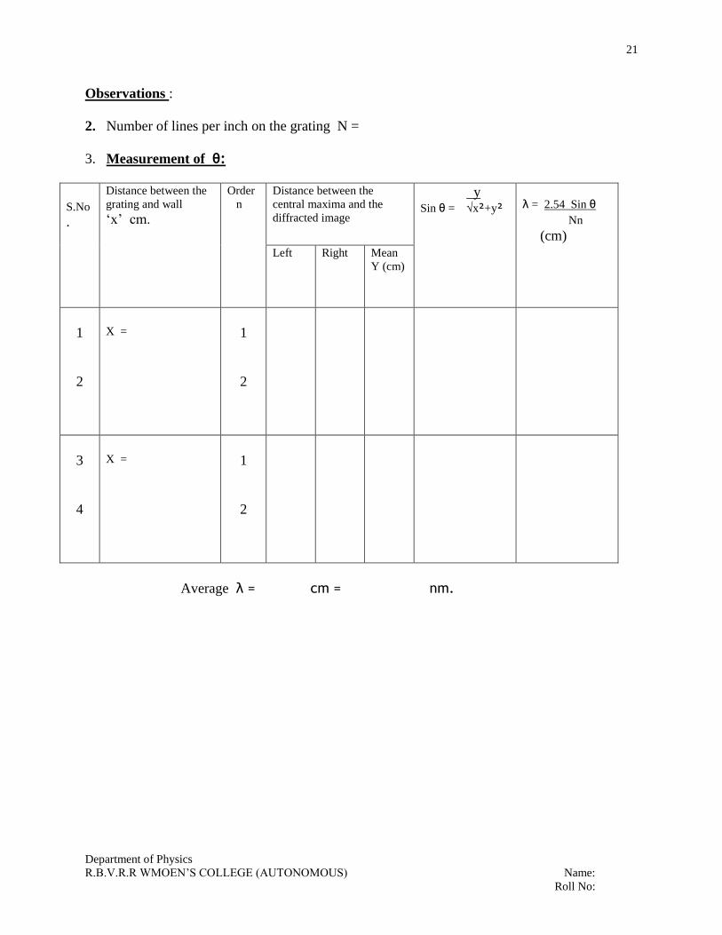
Observations :
2. Number of lines per inch on the grating N =
3. Measurement of θ:
S.No
.
Distance between the
grating and wall ‘x’ cm.
Order
n
Distance between the
central maxima and the
diffracted image
y Sin θ = √x²+y²
λ = 2.54 Sin θ
Nn Nn
(cm)
Left Right Mean
Y (cm)
1
2
X =
1
2
3
4
X =
1
2
Average λ = cm = nm.

22
Department of Physics
R.B.V.R.R WMOEN’S COLLEGE (AUTONOMOUS) Name:
Roll No:
Date:
6. DIFFRACTION GRATING – MINIMUM DEVIATION
Aim : To determine the wavelength of the laser source using a plane transmission grating in the
minimum deviation position.
Apparatus : Plane transmission grating, laser source, rotating stand.
Formula : λ = 2.54 ( 2 Sin (Dm/2))
N n
Where λ = wavelength of laser
Dm = angle of minimum deviation
N = number of lines per inch on grating
n = order of the maxima (spectrum).
D = i + θ Tan Dm = YI /x
Fig. (1) Fig. (2)
Fig. (3)

23
Department of Physics
R.B.V.R.R WMOEN’S COLLEGE (AUTONOMOUS) Name:
Roll No:
Theory : A system of large number of equally spaced indentical parallel slits on a glass plate is
called diffraction grating.
Grating element = width of the slit (e) + width of the opaque interval (d)
The condition for principal maxima in oblique incidence is
(e+d) (Sin i + Sin θ ) = n λ -------------(1)
Where ‘n’ is the order of the principal maxima
n = 0 is called zero order maxima
n = 1 is called first order maxima
n = 2 is called second order maxima
These principle maxima are due to interference and are located in the central maximum of
the diffraction pattern.
When the angle of deviation is minimum i = θ and D = Dm
Dm = 2i = 2 θ or i = Dm/2 and θ = Dm/2
Substituting these values in equation (1)
2.54 2 Sin (Dm/2) = nλ
N
λ = 2.54 2 Sin (Dm/2)
N n
As there are N number of parallel lines per inch, the grating element (e + d) = 2.54/N.
Procedure :
1. Keep the grating on a rotating stand normal to the laser beam and measure its distance ‘x’
from the wall. Adjust the plane of the grating such that all the maxima of the spectrum lie in
the same horizontal plane.
2. Looking at the first order diffracted image to the right on the wall, rotate the grating till the
image moves closest to the central maxima. Measure the distance (YI ) of the image from the
central maxima.
3. Repeat the experiment for second order image to the right and measure the distance YII
4. Measure the distances YI and YII for left side images also, after repeating the 2nd and
3rdsteps.
5. Now repeat the experiment for different values of x.
6.Calculate the value of ‘λ’ using the given formula.
Precautions :
1. Good quality grating should be used. Otherwise, the result obtained will have an error.
2. The plane of the grating should be adjusted normal to the laser source.
3. The ruled surface of the grating should face the light and it should never be touched.
Result :
Lecturer signature with Date:

24
Department of Physics
R.B.V.R.R WMOEN’S COLLEGE (AUTONOMOUS) Name:
Roll No:
Observations :
Number of lines per inch on the grating N =
First order:
S.NO.
Perpendicular
distance between
grating and wall
x cm.
Distance of the diffracted image
from the central maxima at
minimum deviation position
YI cm.
YI/x Angle of
minimum
deviation
Dm=tan-1 YI
x
λ = 2.54 2 Sin (Dm/2) cm
N n
Right Left Mean
1
2
3
Distance of the second order
diffracted image from the central
spot at minimum deviation
position YII cm.
YII/x Dm=tan-1 YII
x
λ = 2.54 2 Sin (Dm/2) cm
N n
Right Left Mean
4
5
6
Average = cm
λ = nm.

25
Department of Physics
R.B.V.R.R WMOEN’S COLLEGE (AUTONOMOUS) Name:
Roll No:
Date:
7. INTERFERENCE - DOUBLE SLIT
ASTRONOMICAL REFRACTING TELESCOPE
Aim: I) To observe interference pattern of spherical waves and circular waves and
II) To determine the magnification factor of refracting astronomical telescope using computer
simulation
Procedure: Part – I
a) Click start
b) Double click phy practicals
c) Double click ph(11e)
d) Double click ph(11e)
e) Double click Interference pattern experiment.
1. Read the instructions given on the screen completely to start the experiment.
2. Select the values of wavelength and distance of two sources(Ф) as input and assume its
order as ‘n’.
3. Keep input values constant, vary n values note down the values of path lengths for
constructive and destructive patterns.
4. Repeat the experiment for difference values of λ, Ф and tabulate the readings.
5. Calculate and verify the values of path lengths ‘ΔS’
Part – II
a) Click start
b) Double click phy practicals
c) Double click ph(11e)
d) Double click ph(11e)
e) Double click Interference pattern experiment.

26
Department of Physics
R.B.V.R.R WMOEN’S COLLEGE (AUTONOMOUS) Name:
Roll No:
1. Read the instructions given on the screen completely to start the experiment.
2. Select the values of objective (f1) and eye piece(f2) focal length respectively.
3. Keep f1, f2 as constant, vary the objective angle and eyepiece angle and note down the
values of magnification factor.
4. Repeat the experiment for set of values of f1, f2 and tabulate the readings of their
respective angles.
5. Calculate and verify magnification factor.
Formula:
V = - f1 / f2
Where f1 = focal length of objective
f2 = focal length of eyepiece
V = magnification factor
Result:
Lecturer signature with date:
27
Department of Physics
R.B.V.R.R WMOEN’S COLLEGE (AUTONOMOUS) Name:
Roll No:
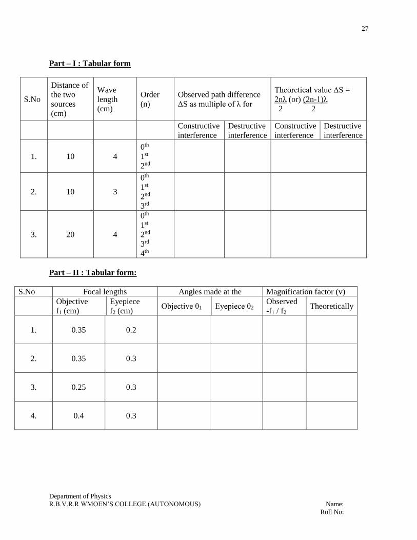
Part – I : Tabular form
S.No
Distance of
the two
sources
(cm)
Wave
length
(cm)
Order
(n)
Observed path difference
ΔS as multiple of λ for
Theoretical value ΔS =
2nλ (or) (2n-1)λ
2 2
Constructive
interference
Destructive
interference
Constructive
interference
Destructive
interference
1. 10 4
0th
1st
2nd
2. 10 3
0th
1st
2nd
3rd
3. 20 4
0th
1st
2nd
3rd
4th
Part – II : Tabular form:
S.No Focal lengths Angles made at the Magnification factor (v)
Objective
f1 (cm)
Eyepiece
f2 (cm) Objective θ1 Eyepiece θ2
Observed
-f1 / f2 Theoretically
1. 0.35 0.2
2. 0.35 0.3
3. 0.25 0.3
4. 0.4 0.3