1. ------ind- 2011 0588 cz- en- ------ 20111128 --- --- projet
TRANSCRIPT

C z e c h M e t r o l o g y I n s t i t u t e Okružní 31, 638 00
Brno
1. ------IND- 2011 0588 CZ- EN- ------ 20111128 --- --- PROJET
The Czech Metrology Institute (CMI), as the competent local body for stipulating metrological and technical requirements for specified measuring devices and for stipulating test methods for type approval and for verification of specified measuring devices pursuant to Section 14(1) of Act No 505/1990 Coll., on Metrology, as amended, and pursuant to the provisions of Section 172 et seq. of Act No 500/2004 Coll., the Administrative Code, as amended (hereinafter the "AC"), commenced ex officio proceedings on 30 September 2011 pursuant to Section 46 of the AC, and based on supporting documents issues this:
I. MEASURE OF A GENERAL NATURE
number: 0111-OOP-C022-11
reference No 0313/022/11/Pos.,
publication date: 30 September 2011.
stipulating metrological and technical requirements for specified measuring devices, including test methods for type approval and verification of specified measuring devices:
"electricity meters"
Taking into account relevant EU legislation and the national legislation of the Czech Republic, electricity meters are a type of measuring device whose introduction onto the market and into circulation, from the perspective of the applicability of this legislation, is classified into three groups, as follows:
a) Class A, B and C watt-hour electricity meters intended for use in residential, commercial and light industrial applications;
b) watt-hour electricity meters intended for applications other than residential, commercial and light industry, and electricity meter functions pursuant to this paragraph and paragraph a) that these electricity meters possess except for measuring resistive power, for example measurement of reactive power;
c) Class 2 inductive electricity meters for measuring resistive power, marked with the EEC marking.

Measure of a General Nature No. 0111-OOP-C022-11
For electricity meters pursuant to a), the process of placing them on the market and into operation, including metrological requirements for measuring devices and their test methods, is covered by Government Order No 464/2005 Coll., establishing technical requirements for measuring instruments1) (hereinafter the "Government Order"). For these electricity meters, this Measure of a General Nature specifies only metrological and technical requirements and test methods that are applied during the verification of these measuring instruments once they have been placed on the market and into operation, i.e. during subsequent verification pursuant to Chapter 7. However, these requirements and methods are in accordance with the Government Order and relevant requirements of harmonised standards.
For electricity meters and electricity meter functions pursuant to b) that are not covered by the aforementioned Government Order, this regulation specifies both metrological and technical requirements and test methods to be applied when they are being placed on the market, i.e. during type approval pursuant to Chapter 5 and during initial verification pursuant to Chapter 6, and metrological and technical requirements and test methods for subsequent verification pursuant to Chapter 7, performed once they have been put into circulation. These activities are not subject to European legislation, and are governed by Act No 505/1990 Coll., on metrology, as amended.
In the case of electricity meters marked with the EEC marking pursuant to c), the process of putting them into circulation is covered by a special regulation2).
1 Basic definitions For the purposes of this measure of a general nature, terminology and definitions contained in TNI 01 0115 (VIM3)) and the following apply:
1.1 electricity meter: a device for the measurement of energy by integrating power over a given time
1.1.1 watt-hour electricity meter: a device for the measurement of resistive energy by integrating resistive power over a given time
1.1.2 var-hour electricity meter: a device for the measurement of reactive energy by integrating reactive power over a given time
1.2 electromechanical induction meter: an electricity meter in which currents in fixed coils interact with currents induced in a conductive rotor (rotors), which causes its (their) movement proportional to the measured energy
1.3 solid-state electricity meter: an electricity meter in which current and voltage interact with solid-state (electronic) components to create an output signal proportional to measured energy
1.4 directly connected electricity meter: an electricity meter intended for direct connection to the electrical grid
1.5 electricity meter connected via a transformer: an electricity meter intended for connection to the electrical grid via one or more external instrument transformers
1.6 multi-rate electricity meter: an electricity meter equipped with several registers, each of which is active during specified intervals corresponding to various rates
1) This government order implements Directive 2004/22/EC of the European Parliament and of the Council of 31 March 2004 on measuring instruments into Czech legislation. 2) Decree No 338/2000 Coll., establishing requirements for electricity meters bearing the EEC marking. 3) International Vocabulary of Metrology - Basic and General Concepts and Associated Terms (VIM).
2

Measure of a General Nature No. 0111-OOP-C022-11
1.7 electricity meter class: a quality designation for electricity meters that meet technical and metrological requirements specified for a given class of electricity meters
1.7.1 electricity meter accuracy classes 0.5, 1, 2, 3, 0.2 S and 0.5 S: a quality designation for electricity meters that meet technical and metrological requirements specified by relevant technical standards, and whose type has been approved pursuant to the Metrology Act; the number in the class designation expresses the electricity meter's accuracy class
1.7.2 electricity meter classes A, B and C: a quality designation for electricity meters that meet technical and metrological requirements specified by Government Order No 464/2005 Coll., establishing technical requirements for measuring instruments1), and that have been placed onto the market and into operation using a conformity assessment process
1.8 current, I: electrical current flowing through the electricity meter
1.8.1 start-up current, Ist: the lowest declared current value for which the electricity meter records electrical energy for a unity power factory (for three-phase electricity meters for a symmetrical load)
1.8.2 minimum current, Imin: the lowest current value for which this regulation specifies accuracy requirements; for Imin and from Imin to Itr , accuracy requirements are relaxed
1.8.3 transient current, Itr: the current value from which until Imax this regulation's accuracy requirements apply
1.8.4 maximum current, Imax: the highest current value for which the electricity meter still meets the regulation's accuracy requirements
1.8.5 base current, Ib: the current value on which the important properties of a directly connected electricity meter are based
1.8.6 nominal current, In: in the case of an electricity meter connected via a transformer, this is the current value for which the electricity meter was designed
1.8.7 reference current, Iref:
for directly connected electricity meters, this is 10x the transient current NOTE 1 – This value is the same as base current Ib.
for electricity meters connected via a current transformer, this is 20x the transient current NOTE 2 – This value is the same as nominal current In.
1.9 reference voltage, Un: the voltage value on which the electricity meter's important properties are based NOTE – The reference voltage can have more than one value.
1.10 reference frequency, fn: the frequency value on which the electricity meter's important properties are based
1.11 maximum permissible error: expressed as the limits of relative error in % given by the formula:
relative error (v %) = energy recorded by the electricity meter – actual energy
× 100 actual energy
NOTE – Because the actual energy cannot be determined, it is approximated with a value read by a reference electricity meter with an established uncertainty.
3

Measure of a General Nature No. 0111-OOP-C022-11
2 Metrological requirements Metrological requirements for watt-hour electricity meters intended for residential, commercial and light industrial use are based on requirements of a Government Order1), utilising relevant requirements of harmonised standards.
Metrological requirements for watt-hour electricity meters intended for other than residential, commercial and light industrial uses are either the same as those in the Government Order, or where this is not the case, have been adopted from European standards.
Metrological requirements for var-hour electricity meters have been adopted from European standards.
Metrological requirements for watt-hour electricity meters bearing the EEC marking are based on requirements applied during EEC type approval pursuant to a special regulation2).
During the verification of electricity meters whose type was approved pursuant to Act No 505/1990 Coll., on metrology, as amended, metrological requirements applicable when they were being put into circulation are applied.
2.1 Specified service conditions
2.1.1 Voltage range
Electricity meters must measure energy within the limits of maximum permissible error over a voltage range of ± 10 % of nominal voltage.
2.1.2 Frequency range
Electricity meters must measure energy within the limits of maximum permissible error over a frequency range of ± 10 % of nominal frequency.
2.1.3 Current range
Electricity meters must measure energy within the limits of maximum permissible error over a current range of Imin to Imax at cos φ = 0.5 inductive to cos φ = 0.8 capacitive.
2.1.4 Ambient temperature range
Electricity meters must measure energy within the limits of maximum permissible error over a temperature range specified by the manufacturer.
2.2 Maximum permissible error
2.2.1 Maximum permissible errors for watt-hour electromechanical electricity meters of accuracy class 0.5 during type approval
Maximum permissible errors for type approval listed below apply only to electromechanical watt-hour electricity meters of accuracy class 0.5 (these electricity meters are not covered by the Government Order, as they are not intended for use in residential, commercial and light industrial applications).
Under reference conditions, relative errors of electricity meters must not exceed maximum permissible errors expressed as limits of relative error listed in Tables 1 and 2.
If an electricity meter is designed for bi-directional measurement of energy, values listed in Tables 1 and 2 apply to both directions.
Table 1 – Maximum permissible errors for single-phase and three-phase electricity meters of accuracy class 0.5 with symmetric loading
Current value Power factor Limits of relative error in %
4

Measure of a General Nature No. 0111-OOP-C022-11
for directly connected meters
for meters connected via measurement transformers
0.05 Ib ≤ I < 0.1 Ib 0.02In ≤ I < 0.05In 1 ± 1.0
0.1Ib ≤ I ≤ Imax 0.05In ≤ I ≤ Imax 1 ± 0.5
0.1Ib ≤ I < 0.2 Ib 0.05In ≤ I < 0.1In 0.5 inductive 0.8 capacitive
± 1.3 ± 1.3
0.2Ib ≤ I ≤ Imax 0.1In ≤ I ≤ Imax 0.5 inductive 0.8 capacitive
± 0.8 ± 0.8
Table 2 – Maximum permissible errors for three-phase electricity meters of accuracy class 0.5
with one phase loaded, but with symmetrical three-phase power on voltage circuits
Current value
Power factor Limits of relative error in % for directly connected
meters
for meters connected via measurement transformers
0.2Ib ≤ I < Ib 0.1In ≤ I ≤ In 1 ± 1.5
0.5 Ib 0.2 In 0.5 inductive ± 1.5
Ib Ia 0.5 inductive ± 1.5
Ib ≤ I ≤ Imax In ≤ I ≤ Imax 1 –
2.2.2 Maximum permissible errors for solid-state watt-hour meters of accuracy class 0.2 S and 0.5 S during type approval
The maximum permissible errors for type approval listed below apply only to solid-state watt-hour electricity meters of accuracy class 0.2 S and 0.5 S (these electricity meters are not covered by the Government Order, as they are not intended for use in residential, commercial and light industrial applications).
Under reference conditions, relative errors of electricity meters must not exceed maximum permissible errors expressed as limits of relative error listed in Tables 3 and 4.
If an electricity meter is designed for bi-directional measurement of energy, values listed in Tables 3 and 4 apply to both directions.
Table 3 – Maximum permissible errors for solid-state watt-hour meters of accuracy class 0.2 S and 0.5 S with symmetrical loading
Current value Power factor Limits of relative error in % u for
meters of accuracy class
0,2 S 0,5 S
0.01In ≤ I < 0.05In 1 ± 0.4 ± 1.0
0.05In ≤ I ≤ Imax 1 ± 0.2 ± 0.5
0.02In ≤ I < 0.1In 0.5 inductive 0.8 capacitive
± 0.5 ± 0.5
± 1.0 ± 1.0
5

Measure of a General Nature No. 0111-OOP-C022-11
0.1In ≤ I ≤ Imax 0.5 inductive 0.8 capacitive
± 0.3 ± 0.3
± 0.6 ± 0.6
Table 4 – Maximum permissible errors for solid-state watt-hour meters of accuracy class 0.2 S and 0.5 S with one phase loaded, but with symmetrical three-phase power on voltage circuits
Current value Power factor Limits of relative error in % u for
meters of accuracy class
0.2 S 0.5 S
0.05In ≤ I ≤ Imax 1 ± 0.3 ± 0.6
0.1In ≤ I ≤ Imax 0.5 inductive ± 0.4 ± 1.0
2.2.3 Maximum permissible errors for solid-state electricity meters during measurement of reactive power
Maximum permissible errors during measurement of reactive power apply only for accuracy tests performed during type approval of solid-state electricity meters intended for the measurement of this type of energy, which is not within the scope of the Government Order.
Under reference conditions, relative errors of electricity meters must not exceed maximum permissible errors expressed as limits of relative error listed in Tables 5 and 6.
Table 5 –Maximum permissible errors for single-phase and three-phase electricity meters with symmetric loading
Current value sin φ (inductive or capacitive)
Limits of relative error in % u for meters of accuracy class
for directly connected meters
for meters connected via measurement transformers 0.5 S 1 2 3
0.05Ib ≤ I < 0.1 Ib 0.01In ≤ I < 0.05In 1 ± 1.0 ± 1.5 – –
0.1Ib ≤ I ≤ Imax 0.05In ≤ I ≤ Imax 1 ± 0.5 ± 1.0 – –
0.05Ib ≤ I < 0.1Ib 0.02In ≤ I < 0.05In 1 – – ± 2.5 ± 4.0
0.1Ib ≤ I ≤ Imax 0.05In ≤ I ≤ Imax 1 – – ± 2.0 ± 3.0
0.1Ib ≤ I < 0.2 Ib 0.05In ≤ I < 0.1In 0.5 ± 1.0 ± 1.5 ± 2.5 ± 4.0
0.2Ib ≤ I ≤ Imax 0.1In ≤ I ≤ Imax 0.5 ± 0.5 ± 1.0 ± 2.0 ± 3.0
Table 6 –Maximum permissible errors for three-phase electricity meters with one phase loaded, but with symmetrical three-phase power on voltage circuits
Current value sin φ (inductive or capacitive)
Limits of relative error in % u for meters of accuracy class
for directly connected meters
for meters connected via measurement transformers 0.5 S 1 2 3
0.1Ib ≤ I ≤ Imax 0.05In ≤ I ≤ Imax 1 ± 0.7 ± 1.5 ± 3.0 ± 4.0
0.2Ib ≤ I ≤ Imax 0.1In ≤ I ≤ Imax 0.5 ± 1.0 ± 2.0 ± 3.0 ± 4.0
6

Measure of a General Nature No. 0111-OOP-C022-11
2.2.5 Maximum permissible errors during verification
During verification under reference conditions, electricity meters must not exceed limit errors listed for individual meter types and currents listed in Tables 24 to 30.
2.2.6 Maximum permissible errors during use
During verification of electricity meters in use, performed upon request by a party whose interests may be significantly damaged by incorrect measurement, double the values of maximum permissible errors listed for individual meter types in Tables 24 to 30 are used. During this verification, start-up, no-load operation and meter dial/display requirements do not change.
2.3 No-load operation
An electricity meter must not record any energy if no current is passing through it.
2.4 Electricity meter start-up
2.4.1 Start-up of watt-hour electricity meters
An electricity meter must begin measuring resistive power and continue recording it at a reference voltage of Un, cos φ = 1 and a current specified in applicable Tables 7 and 8.
Table 7 – Start-up currents for accuracy classes 0.2 S, 0.5 S, 0.5, 1 and 2
Electricity meter Accuracy class
0.2 S 0.5 S 0.5 1 2
Electromechanical for direct connection – – 0.003Ib 0.004Ib 0.005Ib
Electromechanical for connection via a transformer – – 0.002In 0.002In 0.003In
Solid-state for direct connection – 0.001Ib – 0.004Ib 0.005Ib
Solid-state for connection via a transformer 0.001In 0.001In – 0.002In 0.003In
Table 8 – Start-up currents for classes A, B and C
Electricity meter Class
A B C
Electromechanical for direct connection 0,05Itr 0,04Itr –
Electromechanical for connection via a transformer 0,06Itr 0,04Itr –
Solid-state for direct connection 0,05Itr 0,04Itr 0,04Itr
Solid-state for connection via a transformer 0,06Itr 0,04Itr 0,02Itr
2.4.2 Start-up of var-hour electricity meters
An electricity meter must begin measuring reactive power and continue recording it at a reference voltage of Un, sin φ = 1 and a current specified in Table 9.
Table 9 – Start-up currents for accuracy classes 0.5 S, 1, 2 and 3
Electricity meters for Accuracy class
0.5 S 1 2 3
direct connection 0.002Ib 0.004Ib 0.005Ib 0.010Ib
7

Measure of a General Nature No. 0111-OOP-C022-11
connection via a current transformer 0.001In 0.002In 0.003In 0.005In
3 Technical requirements Technical requirements for watt-hour electricity meters intended for residential, commercial and light industrial use are based on requirements of a Government Order1), utilising relevant requirements of harmonised standards.
Technical requirements for watt-hour electricity meters intended for other than residential, commercial and light industrial uses are either the same as those in the Government Order, or where this is not the case, have been adopted from European standards.
Technical requirements for var-hour electricity meters have been adopted from European standards.
Technical requirements for watt-hour electricity meters bearing the EEC marking are based on requirements applied during EEC type approval pursuant to a special regulation2).
During the verification of electricity meters whose type was approved pursuant to Act No 505/1990 Coll., on metrology, as amended, metrological requirements applicable when they were being put into circulation are applied.
3.1 Electricity meter design
Electricity meters must be designed to maintain suitable stability of their metrological properties during the entire duration of their intended use (this duration is estimated by the manufacturer), presuming that they have been correctly installed, maintained and used in accordance with the manufacturer's instructions and in an environment for which they are intended.
3.2 Casing
An electricity meter must have a casing that can be sealed so that the meter's inner parts cannot be accessed without damaging the seal(s).
The outer casing must not be removable without the use of a tool.
The electricity meter's casing must be rigid enough so that any temporary deformation does not prevent the meter from working properly.
3.3 Counter
Electricity meters must have a metrologically controlled counter. It can be a mechanical device composed of cylinders, or an electronic display.
Electricity meters intended for measuring several types of energy must indicate which energy is currently being measured.
Multi-rate electricity meters must indicate which rate is currently in effect.
The information on the counter must correspond to rotations of a rotor or number of impulses of a test diode or number of impulses for remote measurement. This relationship is given by a constant marked on the electricity meter's label.
The total electrical energy counter must have sufficient digits to ensure that the indication does not return to its initial value if the electricity meter is in operation for 4000 hours at full load (I = Imax, U = Uref a cos φ (or sin φ) = 1). The counter must be impossible to zero without removing seals.
In the case of a power outage, the value of the measured electrical energy must remain ascertainable for at least four months.
8

Measure of a General Nature No. 0111-OOP-C022-11
3.4 Software
Software that is crucial for metrological properties must be identifiable and must be secured. It must be possible to identify software in a simple manner. Evidence of each intervention must be available.
3.5 Auxiliary equipment
A meter's metrological properties must not be affected in any way by the connection of other auxiliary equipment to this meter, by no property of connected auxiliary equipment, nor by remotely connected auxiliary equipment that communicates with the meter.
3.6 Physical requirements
The manufacturer must specify the physical environment for which the electricity meter is intended.
Electricity meters must be designed and built to prevent any danger during normal use and under normal conditions; especially ensuring the following:
• human safety from injury from electrical current;
• human safety from the effects of excessive heat;
• prevention of the spread of fire;
• protection from ingress of solid objects, dust and water.
3.7 Environmental conditions
The manufacturer must specify the upper and lower temperature limits for the specified service range, for the maximum service range and for storage and transport conditions.
3.8 Electrical requirements
3.8.1 Temperature rise
Under nominal service conditions, electrical circuits and insulation must not reach a temperature that could negatively affect the electricity meter's activity.
3.8.2 Insulation
An electricity meter and its built-in auxiliary equipment, if any, must maintain adequate insulation properties under normal conditions, taking into account influences of the external environment and various voltages that they are subjected to under normal conditions.
3.8.3 Influence of short-circuit overcurrents
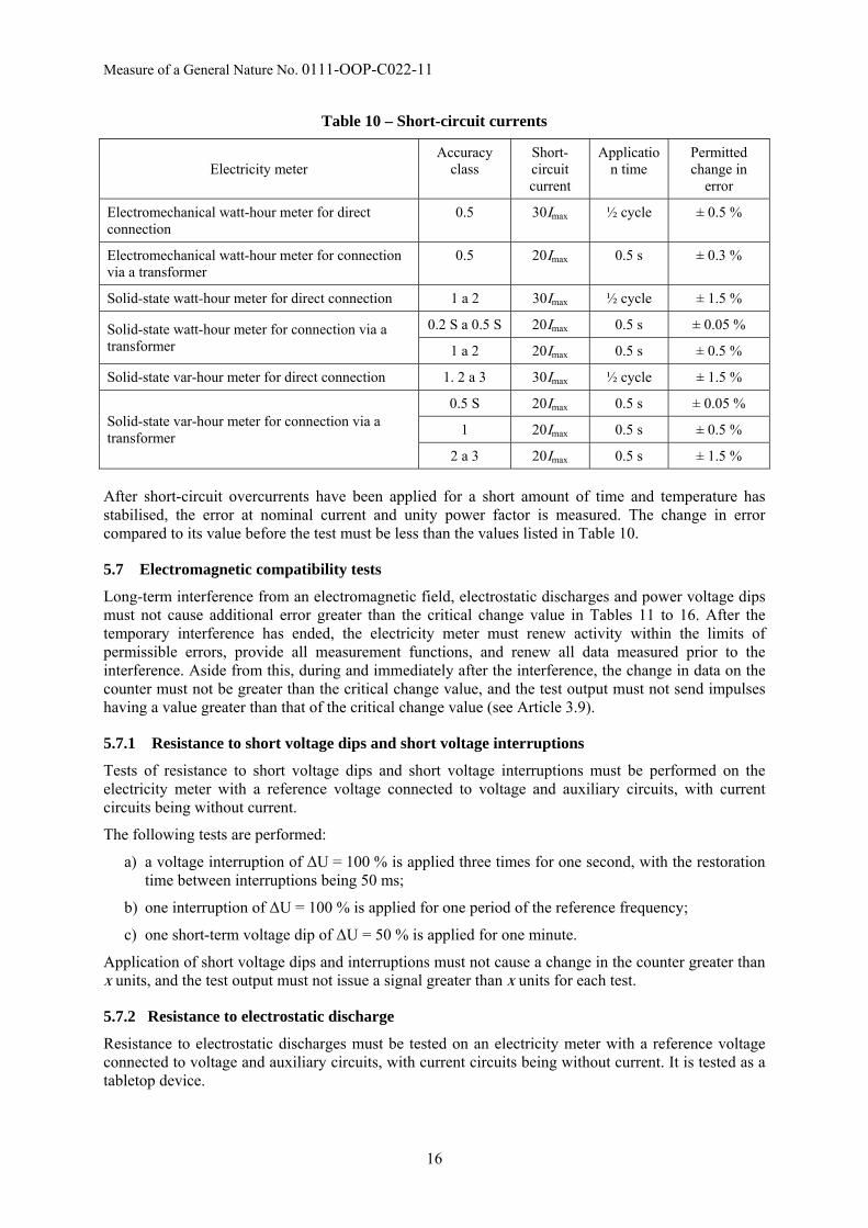
Short-term current overload must not damage an electricity meter. Once original service conditions have been restored, the electricity meter must function correctly, and changes to error for nominal current at unity power factor must not exceed the values listed in Table 10.
3.9 Electromagnetic compatibility
An electricity meter must conform to a Class E2 electromagnetic environment, and must also meet the following requirements.
During electromagnetic interference and immediately after it has ended,
a) none of the outputs intended for testing the accuracy of the electricity meter may send impulses or signals corresponding to electrical energy greater than the critical change value;
b) and within a reasonable time after the interference has ended, the meter:
• must renew its functionality within the limits of maximum permissible error (MPE),
9
Measure of a General Nature No. 0111-OOP-C022-11
• must provide all measurement functions,
• must allow the recovery of all values measured immediately prior to the start of the interference,
• must not indicate a change in the recorded electrical energy greater than the critical change value.
The critical value x, in kWh, is
x = m · Uref · Imax · 10–6
where m is the number of the meter's measuring elements
Uref is the reference voltage in volts;
Imax is the maximum current in amperes.
3.10 Resistance to tampering
An electricity meter must be designed so that any physical tampering with the casing, window or terminal cover that is capable of affecting measurement accuracy causes visible and permanent damage to the meter or to official or security markings, thus providing proof of tampering.
4 Markings
4.1 An electricity meter's identification label must contain at least the following information:
• the manufacturer's name or trademark;
• type;
• serial number and year of manufacture;
• the electricity meter's class
• reference voltage
• reference (or base or nominal) current;
• maximum current;
• minimum current (not required for electricity meters approved before the Government Order coming into effect);
• reference frequency;
• the meter's constant;
• specified service temperature range (not required for electricity meters approved before the Government Order coming into effect);
• type of distribution network (graphical symbol);
• a double square for a completely insulated electricity mater (if it is) of protection class II;
• the meter's power connection schematic (this need not be on the identification label, but can for example be on the terminal cover).
An electricity meter must also have a mark certifying the manner in which it was placed on the market:
• a type approval marking pursuant to Act No 505/1990 Coll., on metrology, as amended, or an EEC type verification certificate marking pursuant to the Government Order;
• the "CE" conformance marking for electricity meters approved prior to the date the Government Order came into effect;
10

Measure of a General Nature No. 0111-OOP-C022-11
• the "CE" conformance marking and additional metrological markings for electricity meters approved pursuant to the Government Order.
4.2 Location of official markings
Locations of markings are specified by a type approval certificate, an EC type verification certificate or another document applied during conformance assessment during introduction onto the market and into operation.
5 Meter type approval Type approval pursuant to Act No 50ř/1990 Coll., on metrology, as amended, does not apply to Class A, B and C watt-hour electricity meters intended for use in residential, commercial and light industrial applications. These meters are introduced into the market and into operation with a conformity assessment pursuant to the Government Order1).
Only the following are subject to type approval pursuant to Act No 50ř/1990 Coll., on metrology, as amended:
a) watt-hour electricity meters intended for use other than in residential, commercial and light industrial applications;
b) var-hour electricity meters of class 0.5, 1, 2 and 3, or the function of measuring reactive energy for electricity meters intended for measurement of several types of energy.
5.1 In general
The type approval process for an electricity meter includes the following:
• an external inspection;
• physical resistance tests;
• environmental resistance tests;
• electrical property influence tests;
• electromagnetic compatibility (EMC) tests;
• functional tests.
5.2 External inspection
During external inspection of an electricity meter, the following is assessed:
• that prescribed technical documentation is complete;
• that metrological and technical characteristics specified by the manufacturer in the documentation meet the requirements of this regulation listed in Articles 2 and 3;
• that the electricity meter is complete and its condition is as prescribed in the technical documentation;
• that the electricity meter's software version is as specified by the manufacturer.
5.3 Performing tests during type approval
5.3.1 Test equipment requirements
Measurement stations for testing electricity meters must be equipped with a reference electricity meter with valid metrological traceability. The measurement station as a whole must have been verified with a functional station check.
11

Measure of a General Nature No. 0111-OOP-C022-11
The test equipment must allow errors in electricity meters to be determined with an uncertainty equal to at most 1/5 of the relative error limits listed in Tables 1 to 5. During testing of Class 0.2 S electricity meters, ¼ of these error limits is sufficient.
5.3.2 Reference conditions for testing
Tests are performed in reference conditions on electricity meters with their cover in place, and connected to the test equipment according to the manufacturer's connection schematic.
For reference conditions, the values listed in Tables 20 to 22 apply.
Aside from these specified conditions, the laboratory may not be subject to disturbances in the form physical vibrations.
5.3.3 Preparing electricity meters for testing
Prior to being tested, the temperature of electricity meters must be allowed to stabilise for at least 6 hours in a room at (23 ± 5) °C.
Prior to the performance of individual tests, in order to achieve working temperature, electricity meters must have their voltage circuits connected to a reference voltage for at least:
• 30 minutes for electromechanical electricity meters,
• 5 minutes for solid-state electricity meters.
5.4 Physical resistance tests
5.4.1 Spring hammer test
A test of the physical resistance of an electricity meter's casing must be performed using a spring-actuated hammer on an electricity meter installed in its normal working position.
The spring hammer must exert a kinetic energy of 0,2 J ± 0,02 J on the external surface of the electricity meter's outer casing (including windows) and on the terminal cover.
The meter passes this test if its casing and terminal cover is not damaged to an extent that could influence its functionality and allow contact with live parts. Minor damage that does not reduce protection from indirect contact or from ingress of solid objects, dust and water is permitted.
5.4.2 Jolt test
A jolt resistance test must be performed on an electricity meter that is not in service, with half-sinus impulses with peak acceleration of 30gn (300 m/s2) and impulse duration of 18 ms. Jolts must be applied to the electricity meter affixed in the test bed in all three axes and in both directions.
After this test, the electricity meter must not exhibit any damage or changes to data, and must work properly according to requirements.
5.4.3 Vibration (sinusoid) test
A test of resistance to sinusoidal vibrations must be performed on an electricity meter that is not in service, with sinusoidal vibrations from 10 Hz to 150 Hz with a transient frequency of 60 Hz, where for:
• f < 60 Hz constant amplitude of movement is 0.075 mm;
• f > 60 Hz constant acceleration is 9.8 m/s2.
The test is performed at one test point with ten repeat cycles per axis.
After this test, the electricity meter must not exhibit any damage or changes to data, and must work properly according to requirements.
12

Measure of a General Nature No. 0111-OOP-C022-11
5.4.4 Heat and fire resistance test
An electricity meter's terminal block, terminal cover and casing must provide sufficient protection from propagation of fire. They should not ignite during excess thermal loading of live parts that they are in contact with.
The heat and fire resistance test must be performed with an incandescent loop on the terminal block at a temperature of 960 °C ± 15 °C, and on the terminal cover and meter casing at a temperature of 650 °C ± 10 °C. The incandescent loop is to be applied for 30 s ± 1 s.
Contact with the incandescent loop may take place at an arbitrary location. Performing this test only on the terminal block is sufficient if it is an integral part of the meter's casing.
5.4.5 Dust and water resistance tests
Dust and water resistance tests must be performed on an out-of-service electricity meter affixed to an artificial wall. Power cables are attached to the meter's terminals and the terminal cover is installed.
The electricity meter must meet IP51 criteria for indoor environments and IP54 criteria for outdoor environments.
5.4.5.1 Dust resistance test
For indoor electricity meters, the inside of the meter is maintained at the same atmospheric pressure as its environment (neither negative nor positive pressure).
Dust may enter the electricity meter only in quantities that do not have a negative impact on its activity. The electricity meter must then meet electrical insulation strength test pursuant to Article 5.6.2.
5.4.5.2 Water resistance test
Water may enter the electricity meter only in quantities that do not have a negative impact on its activity. The electricity meter must then meet electrical insulation strength test pursuant to Article 5.6.2.
5.5 Environmental resistance tests
5.5.1 Dry heat test
A dry heat test must be performed on an out-of-service electricity meter by gradually changing the ambient temperature to +70 °C ± 2°C, and exposing the meter to this temperature for 72 hours.
After this test, the electricity meter must not exhibit any damage or changes to data, and must work properly.
5.5.2 Cold test
A cold test must be performed on an out-of-service electricity meter using the Ab method with gradual temperature change.
An indoor electricity meter is exposed to an ambient temperature of –25 °C ± 3°C for 72 hours, while an outdoor electricity meter is exposed to an ambient temperature of –40 °C ± 3 °C for 16 hours.
After this test, the electricity meter must not exhibit any damage or changes to data, and must work properly.
5.5.3 Cyclical moist heat test
A cyclical moist heat test must be performed on an electricity meter without current, but with a reference voltage connected to power and auxiliary circuits.
13

Measure of a General Nature No. 0111-OOP-C022-11
The electricity meter is exposed to an ambient temperature of +40 °C ± 2 °C (indoor meter) or +55 °C ± 2 °C (outdoor meter) for 12 hours, and then +25 °C ± 3 °C, also for 12 hours (12 h + 12 h cycle). In both cases, relative humidity is 95%. Six test cycles are performed.
Twenty-four hours after the completion of this test, the electricity meter must be subjected to the following tests:
a) an electrical insulation resistance test pursuant to 5.6.2, with the impulse voltage being multiplied by a factor of 0.8;
b) a functional test; the electricity meter must not exhibit any damage or changes to data, and must work properly.
A moist heat test also serves as a corrosion test. The result is assessed visually. There must be no visible signs of corrosion that could affect the meter's functional properties.
5.5.4 Sunlight resistance test
A sunlight resistance test is performed only on outdoor electricity meters that are not in service. The electrometer is irradiated with light for 8 hours, then is left in darkness for 16 hours (an 8 h +16 h cycle). The upper ambient temperature is maintained at +55 ° C. The test lasts for three cycles.
After the test, external appearance and especially legibility of markings must not have changed. The electricity meter must not exhibit reduced functionality.
5.6 Electrical characteristics influence test
5.6.1 Heating tests
A heating test is performed by loading each current circuit with maximum current Imax and each voltage circuit with 1.15Uref for two hours.
After this test, the electricity meter must not exhibit any damage and must pass electrical insulation resistance tests pursuant to Article 5.6.2.
5.6.2 Electrical insulation resistance tests
5.6.2.1 In general
Tests are performed on a complete electricity meter, with the terminal block's top cover and with terminal screws screwed into the core of a conductor of maximum usable diameter.
During voltage impulse and alternating voltage tests, circuits not under test must be grounded.
No breakdown or arcing may occur during the test. After this test, an accuracy test must not reveal any change in error.
5.6.2.2 Voltage impulse test
Electrical insulation resistance tests are performed with voltage impulses in individual circuits, between circuits, and relative to ground.
The impulse source must be capable of generating a normalised voltage impulse 1.2/50 μs with a rise time of ± 30 % and a decline time of ± 20 %, with energy of 0,5 J ± 0,05 J, and an impedance of 500 Ω ± 50 Ω.
The test voltage must be:
for meters of protection class I: 4 kV (for Uref ≤ 300 V) a 1,5 kV (pro Uref ≤ 100 V);
for meters of protection class II: 6 kV (for Uref ≤ 300 V) a 2,5 kV (pro Uref ≤ 100 V).
For each test, the voltage impulse is always applied ten times for one polarity and then ten times for the other polarity. The minimum time between impulses must be 3 s.
14

Measure of a General Nature No. 0111-OOP-C022-11
5.6.2.3 Alternating voltage test
An alternating voltage test is performed at a frequency of 45 Hz to 65 Hz for one minute. The voltage is applied between:
a) all voltage, current and auxiliary circuits connected together and ground;
b) circuits that are not interconnected during meter operation.
The test voltage must be as follows:
for meters of protection class I: 2 kV (tests a and b);
for meters of protection class II: 4 kV (test a), 2 kV (test b).
5.6.3 Short-circuit test
A short-circuit test is performed using current pursuant to Table 10 that is applied for the specified time.
15
Measure of a General Nature No. 0111-OOP-C022-11
Table 10 – Short-circuit currents
Electricity meter Accuracy
class Short-circuit current
Application time
Permitted change in
error
Electromechanical watt-hour meter for direct connection
0.5 30Imax ½ cycle ± 0.5 %
Electromechanical watt-hour meter for connection via a transformer
0.5 20Imax 0.5 s ± 0.3 %
Solid-state watt-hour meter for direct connection 1 a 2 30Imax ½ cycle ± 1.5 %
Solid-state watt-hour meter for connection via a transformer
0.2 S a 0.5 S 20Imax 0.5 s ± 0.05 %
1 a 2 20Imax 0.5 s ± 0.5 %
Solid-state var-hour meter for direct connection 1. 2 a 3 30Imax ½ cycle ± 1.5 %
Solid-state var-hour meter for connection via a transformer
0.5 S 20Imax 0.5 s ± 0.05 %
1 20Imax 0.5 s ± 0.5 %
2 a 3 20Imax 0.5 s ± 1.5 %
After short-circuit overcurrents have been applied for a short amount of time and temperature has stabilised, the error at nominal current and unity power factor is measured. The change in error compared to its value before the test must be less than the values listed in Table 10.
5.7 Electromagnetic compatibility tests
Long-term interference from an electromagnetic field, electrostatic discharges and power voltage dips must not cause additional error greater than the critical change value in Tables 11 to 16. After the temporary interference has ended, the electricity meter must renew activity within the limits of permissible errors, provide all measurement functions, and renew all data measured prior to the interference. Aside from this, during and immediately after the interference, the change in data on the counter must not be greater than the critical change value, and the test output must not send impulses having a value greater than that of the critical change value (see Article 3.9).
5.7.1 Resistance to short voltage dips and short voltage interruptions
Tests of resistance to short voltage dips and short voltage interruptions must be performed on the electricity meter with a reference voltage connected to voltage and auxiliary circuits, with current circuits being without current.
The following tests are performed:
a) a voltage interruption of ΔU = 100 % is applied three times for one second, with the restoration time between interruptions being 50 ms;
b) one interruption of ΔU = 100 % is applied for one period of the reference frequency;
c) one short-term voltage dip of ΔU = 50 % is applied for one minute.
Application of short voltage dips and interruptions must not cause a change in the counter greater than x units, and the test output must not issue a signal greater than x units for each test.
5.7.2 Resistance to electrostatic discharge
Resistance to electrostatic discharges must be tested on an electricity meter with a reference voltage connected to voltage and auxiliary circuits, with current circuits being without current. It is tested as a tabletop device.
16

Measure of a General Nature No. 0111-OOP-C022-11
Ten contact discharges of 8 kV are applied to the metal part of the casing, or ten air discharges of 15 kV are applied to a part of the casing made of insulating material (for protection class II electricity meters).
Application of short voltage dips and interruptions must not cause a change in the counter greater than x units, and the test output must not issue a signal greater than x units for each test.
Temporary deterioration or loss of functionality or output is allowed during the test.
5.7.3 Resistance to a radiated high-frequency electromagnetic field
This test is not performed for electromechanical electricity meters.
The test must be performed for interference in the 80 MHz to 2000 MHz frequency range during 80% AM of a 1 kHz sinus wave. It is tested as a tabletop device.
5.7.3.1 Current test
A reference voltage is connected to voltage and auxiliary circuits, and a reference (or nominal, base) current is connected to current circuits, cos φ (or sin φ) = 1. The intensity of the non-modulated test field is 10 V/m.
The electricity meter's activity must not be disrupted during the test. Additional error must not exceed permitted values in Table 11.
Table 11 –Critical change values for tests of resistance to HF electromagnetic fields
Electricity meter Accuracy class Critical change value
Solid-state watt-hour
0.5 S and 0.2 S ± 1 %
1 ± 2 %
2 ± 3 %
Solid-state var-hour 0.5 S and 1 ± 2 %
2 and 3 ± 3 %
5.7.3.2 No-current test
A reference voltage is connected to voltage and auxiliary circuits, current circuits are without current (open circuit). The intensity of the non-modulated test field is 30 V/m. Application of a high-frequency field must not cause a change in the counter greater than x units, and the test output must not issue a signal greater than x units.
Temporary deterioration or loss of functionality or output is allowed during the test.
5.7.4 Resistance to rapid transient phenomena/impulse groups
Resistance to rapid transient phenomena/impulse groups must be tested on an electricity meter with a reference voltage connected to voltage and auxiliary circuits. A reference current is connected to current circuits, cos φ (or sin φ) = 1. It is tested as a tabletop device.
The length of the cable between the switching device and the electricity meter is 1 m. The repeating frequency is 5 kHz and the test is performed for 60 s at each polarity.
A test voltage of 4 kV must be applied to voltage circuits and current circuits, if they are separate from voltage circuits during normal operation. A test voltage of 2 kV must be applied to auxiliary circuits with a reference voltage higher than 40 V.
Temporary deterioration or loss of functionality or output is allowed during the test. Additional error must not exceed permitted values in Table 12.
17
Measure of a General Nature No. 0111-OOP-C022-11
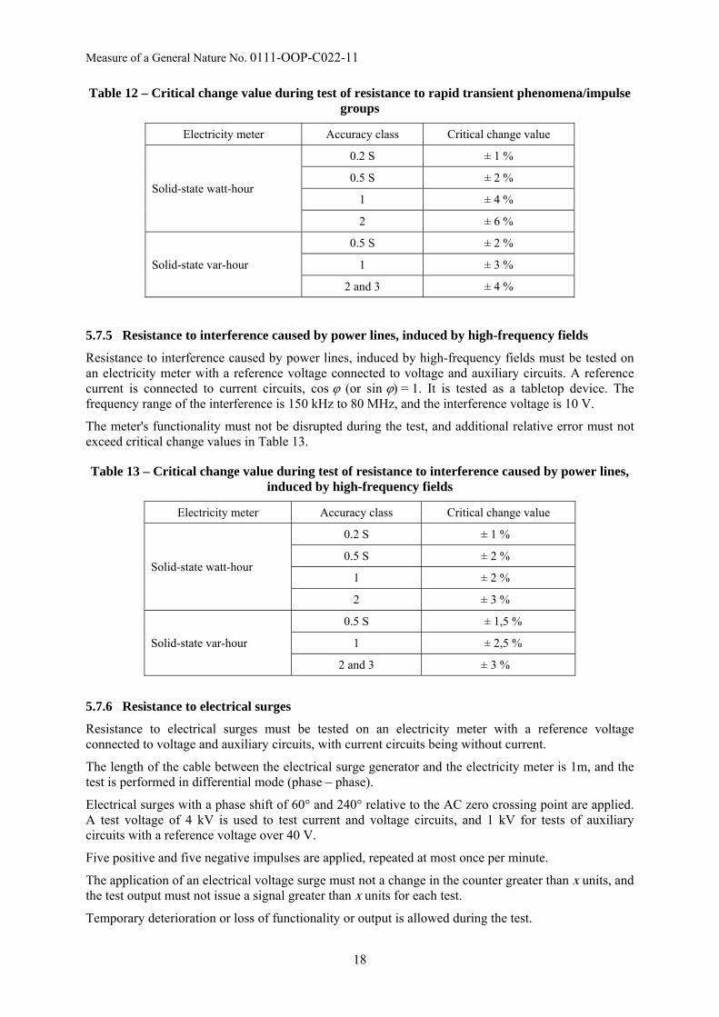
Table 12 – Critical change value during test of resistance to rapid transient phenomena/impulse groups
Electricity meter Accuracy class Critical change value
Solid-state watt-hour
0.2 S ± 1 %
0.5 S ± 2 %
1 ± 4 %
2 ± 6 %
Solid-state var-hour
0.5 S ± 2 %
1 ± 3 %
2 and 3 ± 4 %
5.7.5 Resistance to interference caused by power lines, induced by high-frequency fields
Resistance to interference caused by power lines, induced by high-frequency fields must be tested on an electricity meter with a reference voltage connected to voltage and auxiliary circuits. A reference current is connected to current circuits, cos φ (or sin φ) = 1. It is tested as a tabletop device. The frequency range of the interference is 150 kHz to 80 MHz, and the interference voltage is 10 V.
The meter's functionality must not be disrupted during the test, and additional relative error must not exceed critical change values in Table 13.
Table 13 – Critical change value during test of resistance to interference caused by power lines, induced by high-frequency fields
Electricity meter Accuracy class Critical change value
Solid-state watt-hour
0.2 S ± 1 %
0.5 S ± 2 %
1 ± 2 %
2 ± 3 %
Solid-state var-hour
0.5 S ± 1,5 %
1 ± 2,5 %
2 and 3 ± 3 %
5.7.6 Resistance to electrical surges
Resistance to electrical surges must be tested on an electricity meter with a reference voltage connected to voltage and auxiliary circuits, with current circuits being without current.
The length of the cable between the electrical surge generator and the electricity meter is 1m, and the test is performed in differential mode (phase – phase).
Electrical surges with a phase shift of 60° and 240° relative to the AC zero crossing point are applied. A test voltage of 4 kV is used to test current and voltage circuits, and 1 kV for tests of auxiliary circuits with a reference voltage over 40 V.
Five positive and five negative impulses are applied, repeated at most once per minute.
The application of an electrical voltage surge must not a change in the counter greater than x units, and the test output must not issue a signal greater than x units for each test.
Temporary deterioration or loss of functionality or output is allowed during the test.
18

Measure of a General Nature No. 0111-OOP-C022-11
5.7.7 Resistance to dampened oscillation waves
Resistance to dampened oscillation waves is tested only for electricity meters connected through a voltage transformer, intended for use in electrical power plants and high-voltage substations.
Tests must be performed on an electricity meter with a reference voltage connected to voltage and auxiliary circuits with a reference voltage of > 40 V. A reference current is connected to current circuits, cos φ (or sin φ) = 1. It is tested as a tabletop device.
Dampened 100 kHz (repeat frequency 40 Hz) and 1 MHz (repeat frequency 400 Hz) oscillation waves with common-mode voltage of 2.5 kV and a differential voltage of 1.0 kV are applied to voltage and auxiliary circuits.
The test time is 60 s (15 cycles of 2 seconds on and 2 seconds off for each frequency).
The meter's functionality must not be disrupted during the test, and additional relative error must not exceed critical change values in Table 14.
Table 14 – Critical change value during test of resistance to dampened oscillation waves
Electricity meter Accuracy class Critical change value
Solid-state watt-hour
0.2 S ± 1 %
0.5 S ± 2 %
1 ± 2 %
2 ± 3 %
Solid-state var-hour
0.5 S ± 2,0 %
1 ± 3,0 %
2 and 3 ± 4 %
5.7.8 Resistance to alternating external magnetic fields
Resistance to alternating external magnetic fields must be tested on an electricity meter with a connected reference voltage and a reference current of cos φ (or sin φ) = 1. It is tested as a tabletop device.
An alternating magnetic field of 0.5 mT at the reference frequency is applied to the electricity meter in three perpendicular planes.
The meter's functionality must not be disrupted during the test, and additional relative error must not exceed critical change values in Table 15.
Table 15 – Critical change value during test of resistance to alternating external magnetic fields
Electricity meter Accuracy class Critical change value
Electromechanical watt-hour 0.5 ± 1.5 %
Solid-state watt-hour
0.2 S ± 0.5 %
0.5 S ± 1 %
1 ± 2 %
2 ± 3 %
Solid-state var-hour
0.5 S ± 1.0 %
1 ± 2.0 %
2 and 3 ± 3 %
19

Measure of a General Nature No. 0111-OOP-C022-11
5.7.9 Resistance to direct external magnetic fields
Resistance to direct external magnetic fields must be tested on an electricity meter with a connected reference voltage and a reference current of cos φ (or sin φ) = 1. A direct magnetic field with a magnetomotive voltage of Fm = 1000 A is gradually applied to all accessible surfaces of the electricity meter.
The meter's functionality must not be disrupted during the test, and additional relative error must not exceed critical change values in Table 16.
Table 16 – Critical change value during test of resistance to direct external magnetic fields
Electricity meter Accuracy class Critical change value
Solid-state watt-hour
0.2 S and 0.5 S ± 2 %
1 ± 2 %
2 ± 3 %
Solid-state var-hour 0.5 S and 1 ± 2.0 %
2 and 3 ± 3 %
5.7.10 Suppression of RF interference
Suppression of RF interference must be performed on an electricity meter with a reference voltage connected to voltage and auxiliary terminals and with a current of 0.1Iref and 0.2Iref (or nominal, base), cos φ (or sin φ) = 1. It is tested as a class B tabletop device. A one-metre unshielded cable must be used on each terminal to connect voltage circuits.
The level of high-frequency interference caused by power lines in the 0.15 MHz to 30 MHz frequency range is measured, and radiated in the 30 MHz to 1 GHz frequency range.
Test results must not exceed limits for electromagnetic interference listed in the applicable technical standard.
5.8 Functional tests
5.8.1 No-load test
The no-load test is performed according to Article 7.4.
5.8.2 Start-up test
The start-up test is performed according to Article 7.5.
5.8.3 Accuracy test
The accuracy test is performed according to Article 7.6.
5.8.4 Ambient temperature test
Additional error due to a temperature change (within the electricity meter's specified service range) with respect to the error in reference conditions must not exceed limits for the given accuracy class. These limits are listed in Table 17 in the form of thermal coefficient limits in %/K.
20

Measure of a General Nature No. 0111-OOP-C022-11
Table 17 – Thermal coefficient limits in %/K for tests of influence of ambient temperature on an electricity meter
Connection to mains Load
Thermal coefficient limits in %/K Current Power factor
Electromechanical meters: Accuracy class
0.5
direct 0.1In to Imax
0.2In to Imax 1
0.5 inductive ± 0.03 ± 0.05
via a transformer 0.05In to Imax
0.10In to Imax 1
0.5 inductive ± 0.03 ± 0.05
Solid-state watt-hour meters of accuracy class: Accuracy class
0.2 S 0.5 S 1 2
direct 0.1In to Imax
0.2In to Imax 1
0.5 inductive – –
± 0.03 ± 0.05
± 0.05 ± 0.07
± 0.10 ± 0.15
via a transformer 0.05In to Imax
0.10In to Imax 1
0.5 inductive ± 0.01 ± 0.02
± 0.03 ± 0.05
± 0.05 ± 0.07
± 0.10 ± 0.15
Var-hour meters (solid-state): Accuracy class
0.5 S 1 2 3
direct 0.1Ib to Imax
0.2Ib to Imax 1
0.5 inductive – –
± 0.05 ± 0.10
± 0.10 ± 0.15
± 0.15 ± 0.25
via a transformer 0.05In to Imax
0.10In to Imax 1
0.5 inductive ± 0.03 ± 0.05
± 0.05 ± 0.10
± 0.10 ± 0.15
± 0.15 ± 0.25
5.8.5 Voltage change test
Additional error due to a voltage change of ± 10 %·Un with respect to the error in reference conditions must not exceed limits for the given accuracy class in Table 18.
21

Measure of a General Nature No. 0111-OOP-C022-11
Table 18 – Additional error limits in % during a test of voltage change of ± 10 %·Un
Mains connection Load
Additional error limits in % Current Power factor
Electromechanical meters: Accuracy class
0.5
direct 0.1Ib
0.5Imax
0.5Imax
1 1
0.5 inductive
± 0.8 ± 0.5 ± 0.7
via a transformer 0.1In
0.5Imax
0.5Imax
1 1
0.5 inductive
± 0.8 ± 0.5 ± 0.7
Solid-state watt-hour meters of accuracy class: Accuracy class
0.2 S 0.5 S 1 2
direct 0.05Ib to Imax 0.10Ib to Imax
1 0.5 inductive
– –
± 0.2 ± 0.4
± 0.7 ± 1.0
± 1.0 ± 1.5
via a transformer 0.02In to Imax 0.05In to Imax
1 0.5 inductive
– –
– –
± 0.7 ± 1.0
± 1.0 ± 1.5
via a transformer 0.05In to Imax 0.10In to Imax
1 0.5 inductive
± 0.1 ± 0.2
± 0.2 ± 0.4
– –
– –
Var-hour meters (solid-state): Accuracy class
0.5 S 1 2 3
direct 0.05In to Imax 0.10In to Imax
1 0.5 inductive
– –
± 0.5 ± 1.0
± 1.0 ± 1.5
± 2.0 ± 3.0
via a transformer 0.02In to Imax 0.05In to Imax
1 0.5 inductive
± 0.25 ± 0.5
± 0.5 ± 1.0
± 1.0 ± 1.5
± 2.0 ± 3.0
5.8.6 Frequency change test
Additional error due to a voltage change of ± 2 %·fn with respect to the error in reference conditions must not exceed limits for the given accuracy class in Table 19.
22

Measure of a General Nature No. 0111-OOP-C022-11
Table 19 – Additional error limits in % during a test of frequency change of ± 2 %·fn
Mains connection Load
Additional error limits in % Current Power factor
Electromechanical meters: Accuracy class
0.5
direct 0.1Ib
0.5Imax
0.5Imax
1 1
0.5 inductive
± 0.7 ± 0.6 ± 0.8
via a transformer 0.1In
0.5Imax
0.5Imax
1 1
0.5 inductive
± 0.7 ± 0.6 ± 0.8
Solid-state watt-hour meters of accuracy class: Accuracy class
0.2 S 0.5 S 1 2
direct 0.05Ib to Imax 0.10Ib to Imax
1 0.5 inductive
– –
± 0.2 ± 0.2
± 0.5 ± 0.7
± 0.8 ± 1.0
via a transformer 0.02In to Imax 0.05In to Imax
1 0.5 inductive
– –
– –
± 0.5 ± 0.7
± 0.8 ± 1.0
via a transformer 0.05In to Imax 0.10In to Imax
1 0.5 inductive
± 0.1 ± 0.1
± 0.2 ± 0.2
– –
– –
Var-hour meters (solid-state): Accuracy class
0.5 S 1 2 3
direct 0.05In to Imax 0.10In to Imax
1 0.5 inductive
± 0.25 ± 0.5
± 0.5 ± 1.0
± 2.5 ± 2.5
± 2.5 ± 2.5
via a transformer 0.02In to Imax 0.05In to Imax
1 0.5 inductive
± 0.25 ± 0.5
± 0.5 ± 1.0
± 2.5 ± 2.5
± 2.5 ± 2.5
5.8.7 Counter test
A counter test is performed according to Article 7.7.
6 Initial verification Initial verification pursuant to Act No 505/1990 Coll., on metrology, as amended, does not apply to class A, B and C watt-hour electricity meters intended for residential, commercial and light industrial applications. These meters are introduced onto the market and into operation with a conformity assessment pursuant to the Government Order1).
Initial verification pursuant to Act No 505/1990 Coll., on metrology, as amended, applies only to:
a) watt-hour electricity meters of class 0.2 S, 0.5 S and 0.5;
b) electricity meters intended for use other than in residential, commercial and light industrial applications;
c) var-hour electricity meters of class 0.5, 1, 2 and 3, or the function of measuring reactive energy for electricity meters intended for measurement of several types of energy;
d) class 2 electricity meters for measurement of resistive energy, bearing the EEC marking;
23

Measure of a General Nature No. 0111-OOP-C022-11
e) electricity meters that at the given time have a valid type approval certificate utilising transitory provisions pursuant to Section 9 of the Government Order;
f) electricity meters following repairs.
During initial verification, the same procedure is used as for subsequent verification pursuant to Section 7.
7 Subsequent verification Subsequent verification pursuant to Act No 505/1990 Coll., on metrology, as amended, applies to electricity meters of all types and classes listed in this regulation. The manner in which the electricity has been introduced onto the market and into operation is taken into account during specification of accuracy requirements for verification according to individual meter classes.
7.1. In general
During subsequent verification of electricity meters, the following tests must be performed:
a) a visual inspection;
b) a no-load test;
c) a start-up test;
d) an accuracy test;
e) a counter test.
7.2 Visual inspection
During a visual inspection, an electricity meter submitted for verification is checked whether it matches, including its software version, the approved type or the design of a meter that has received a declaration of conformity within the scope of market introduction. Attention must be paid to checking that labelling pursuant to Article 4.1 is correct and legible.
The electricity meter is also checked for physical damage, and for meters with an electronic display, whether all symbols on the display are visible following connection to power.
Electricity meters that do not match the approved type or the design of a meter that has received a declaration of conformity within the scope of market introduction are not tested further.
7.3 Test conditions
7.3.1 Test equipment requirements
Measurement stations for testing electricity meters must be equipped with a reference electricity meter with a valid calibration sheet. The measurement station as a whole must have been verified with a functional station check.
The test equipment must allow errors in electricity meters to be determined with an uncertainty equal to at most 1/4 of the relative error limits listed in Tables 24 to 30. During testing of Class 0.2 S electricity meters, 1/3 of these error limits is sufficient.
The equipment must also allow verification that requirements of 2.2, 2.3 and 2.4 have clearly been met.
7.3.2 Reference conditions for testing
Tests are performed in reference conditions on electricity meters with their cover in place, and connected to the test equipment according to the manufacturer's connection schematic.
For reference conditions, the values listed in Tables 20 to 22 apply.
24

Measure of a General Nature No. 0111-OOP-C022-11
Aside from these specified conditions, the laboratory may not be subject to disturbances in the form of physical vibrations.
25

Measure of a General Nature No. 0111-OOP-C022-11
Table 20 – Reference conditions for electromechanical watt-hour electricity meters
Influencing factor Reference value Permitted tolerances for meters of
accuracy class Permitted tolerances for
meters of class
0.5 1 2 A B
Ambient temperature Reference
temperature, or if not given, 23 °C
± 1 °C ± 2 °C ± 2 °C ± 2 °C ± 2 °C
Voltage Reference voltage ± 0.5 % ± 1.0 % ± 1.0 % ± 1.0 % ± 1.0 %
Frequency Reference frequency ± 0.2 % ± 0.3 % ± 0.5 % ± 0.5 % ± 0.3 %
Phase sequence L1 – L2 – L3 – – – – –
Voltage asymmetry All phases connected – – – – –
Waveform Sinus voltage and currents
Distortion factor less than:
2 % 2 % 3 % 3 % 2 %
Direct external magnetic field Equal to zero – – – – –
Alternating external magnetic at power line frequency
Equal to zero Value of induction causing a change in error not greater than:
± 0.1 % ± 0.2 % ± 0.3 % ± 0.3 % ± 0.2 %
Activity of auxiliary devices
Auxiliary device not in operation – – – – –
Service position Vertical service position ± 0.5º ± 0.5º ± 0.5º ± 0.5° ± 0.5°
Resistance to interference caused by power lines, induced by HF fields, 150 kHz to 80 MHz
Equal to zero < 1 V < 1 V < 1 V < 1 V < 1 V
26

Measure of a General Nature No. 0111-OOP-C022-11
Table 21 – Reference conditions for solid-state watt-hour electricity meters
Influencing factor Reference value Permitted tolerances for meters of
accuracy class Permitted tolerances for meters
of class
0.2 S 0.5 S 1 2 A B C
Ambient temperature
Reference temperature, or
if not given, 23 °C
± 2 °C ± 2 °C ± 2 °C ± 2 °C ± 2 °C ± 2 °C ± 2 °C
Voltage Reference voltage ± 1.0 % ± 1.0 % ± 1.0 % ± 1.0 % ± 1.0 % ± 1.0 % ± 1.0 %
Frequency Reference frequency ± 0.3 % ± 0.3 % ± 0.3 % ± 0.5 % ± 0.5 % ± 0.3 % ± 0.3 %
Phase sequence L1 – L2 – L3 – – – – – – –
Voltage asymmetry
All phases connected – – – – – – –
Waveform Sinus voltage and currents
Distortion factor less than:
2 % 2 % 2 % 3 % 3 % 2 % 2 %
Direct external magnetic field Equal to zero – – – – – – –
Alternating external magnetic at power line frequency
Equal to zero
Value of induction causing a change in error not greater than b:
± 0.1 % or
< 0.05 mT
± 0.1 % or
< 0.05 mT± 0.2 % ± 3 % ± 0.3 % ± 0.2 % ± 0.1 %
HF electromagnetic fields, 30 kHz to 2 GHz
Equal to zero < 1 V/m < 1 V/m < 1 V/m < 1 V/m < 1 V/m < 1 V/m < 1 V/m
Activity of auxiliary devices
Auxiliary devices not in
operation – – – – – – –
Resistance to interference caused by power lines, induced by HF fields, 150 kHz to 80 MHz
Equal to zero < 1 V < 1 V < 1 V < 1 V < 1 V < 1 V < 1 V
27

Measure of a General Nature No. 0111-OOP-C022-11
Table 22 –Reference conditions for solid-state var-hour electricity meters
Influencing factor Reference value Permitted tolerances for meters of accuracy class
0.5 S 1 2 3
Ambient temperature Reference
temperature, or if not given, 23 °C
± 2 °C ± 2 °C ± 2 °C ± 2 °C
Voltage Reference voltage ± 1.0 % ± 1.0 % ± 1.0 % ± 1.0 %
Frequency Reference frequency ± 0.3 % ± 0.3 % ± 0.5 % ± 0.5 %
Phase sequence L1 – L2 – L3 – – – –
Voltage asymmetry All phases connected – – – –
Waveform Sinus voltage and currents
Non-linear distortion factor less than
2 % 2 % 2 % 3 %
Direct external magnetic field Equal to zero – – – –
Alternating external magnetic at power line frequency
Magnetic induction equal to zero
Value of induction causing a change in error not greater than:
± 0.3 % ± 0.3 % ± 0.3 % ± 0.3 %
HF electromagnetic fields, 30 kHz to 2 GHz Equal to zero < 1 V/m < 1 V/m < 1 V/m < 1 V/m
Activity of auxiliary devices No auxiliary devices in operation
– – – –
Resistance to interference caused by power lines, induced by HF fields, 150 kHz to 80 MHz
Equal to zero < 1 V < 1 V < 1 V < 1 V
7.3.3 Preparing electricity meters for testing
Prior to being tested, the temperature of electricity meters must be allowed to stabilise for at least 6 hours in a room at (23 ± 5) °C.
Prior to the performance of individual tests, in order to achieve working temperature, electricity meters must have their voltage circuits connected to a reference voltage for at least:
• 30 minutes for electromechanical electricity meters,
• 5 minutes for solid-state electricity meters.
7.4 No-load test
7.4.1 No-load test for electromechanical electricity meters
For electricity meters with a mechanical counter, only the lowest-order cylinder may be engaged. Prior to testing, electromechanical meters are set so that the marking on the rotor is visible in the window.
During the test, the following voltages are sequentially applied to voltage circuits:
• 80 % of reference voltage;
• 110 % of reference voltage;
28

Measure of a General Nature No. 0111-OOP-C022-11
with the meter's current circuits not powered.
The test lasts for at least 15 minutes for each voltage.
The meter passes the test if the mark on the rotor does not leave the window.
7.4.2 No-load test for solid-state electricity meters
For solid-state electricity meters, a voltage of 115% of the reference voltage is connected to the voltage circuits, with the meter's current circuits not powered. The minimum test time is calculated according to the following formula:
max
60 10Pk
Kt⋅⋅
=
where k is the meter constant (imp/kWh or rot/kWh);
Pmax is the maximum power measurable by the meter (W);
the value of the constant K0 is given in Table 23.
Table 23 – Values of the constant K0
Accuracy class
Watt-hour meters Var-hour meters
0.2 S 0,5 S 1 2 0.5 S 1 2 3
K0 900 600 600 480 600 600 480 300
The minimum test time in minutes for class A, B and C meters is calculated by the following formula:
sttest IUmkt
⋅⋅⋅⋅
=310240
where k is the meter constant (imp/kWh);
m is the number of measurement elements;
Utest is the test voltage in volts;
Ist is the start-up current in amperes.
The test time for solid-state electricity meters must be at least 15 minutes even if the calculated time t is shorter.
The mater passes the test if the test LED or impulse output for remote measurement has emitted either no impulse or at most one.
7.5 Start-up test
During the start-up test, the electricity meter must begin measuring energy after being connected to a reference voltage of Uref, at cos ϕ (or sin φ) = 1 and application of current according to Table 7, 8 or 9 to current circuits. The rotation of the rotor or impulses issued at the test output are observed.
Various types of electricity meters are tested under the following additional conditions:
• electromechanical meters with a mechanical counter: more than two cylinders may not be engaged;
• electromechanical meters with a mechanical maximum indicator: the maximum indicator must not be engaged;
• electromechanical meters with several reference voltages: for meters with reference voltages or an entire range of reference voltages, the start-up test is performed at the maximum and minimum voltage listed on the label;
29

Measure of a General Nature No. 0111-OOP-C022-11
• meters with two base currents: the start-up test is performed at a start-up current calculated from the smaller base current.
An electromechanical meter passes if the meter's rotor has started moving and has made at least one rotation. The test is performed until the described conditions have been met, but at most for the time it would take for the rotor of the meter under test to theoretically make three rotations (if it measured without errors during start-up current).
A solid-state meter passes if the test LED or impulse output for remote measurement emits at least two impulses. The test is performed until the described conditions have been met, but at most for the time it would take for the test LED of the meter under test or the impulse output for remote measurement to theoretically send at least four impulses (if it measured without errors during start-up current).
7.6 Accuracy test
7.6.1 In general
An accuracy test measures meter errors at currents listed in Tables 24 to 30. An accuracy test must be performed using either:
a) a method that records the number of disc rotations or impulses of the meter under test, or
b) a method that reads data from the counter of the meter under test.
Prior to measuring error at a given current setting, a wait time of at least 5 seconds is required.
7.6.2 Measurement uncertainty
Electricity meter measurement errors must be determined with uncertainties smaller than 1/4 of the relative error limits listed in Tables 24 to 30. An exception to this are solid-state meters of accuracy class 0.2 S, where the measurement uncertainties must be less than 1/3 of the permitted error limits in Table 26.
7.6.3 Special test requirements
For electricity meters with a mechanical counter, only the lowest-order cylinder may be engaged during tests performed by recording disc rotations or impulses of the meter under test. When data is being read from the counter, at most the last two cylinders may be engaged.
For electricity meters with auxiliary devices, the same test conditions and the same error limits apply as for meters without auxiliary devices. Exceptions are meters with a mechanical auxiliary device for measuring maximum values, where the driver must not drive the maximum indicator directly.
For special meter versions, accuracy tests are performed under the following conditions:
• electricity meters with several reference voltages: for meters with reference voltages or an entire range of reference voltages, the test is performed at the maximum and minimum voltage listed on the label;
• electricity meters with two base currents: at the lowest test point, the test is performed at the smaller base current. At all other test points, it is performed at the higher base current.
• electricity meters with a data interface: instead of reading data visually, tests may use a device to read the contents of appropriate registers. These read values and values shown on the display must however be the same (at least on the visible digits of the displayed data). During an accuracy test, this comparison must be performed at least once;
• broadcast electricity meters: for meters equipped with terminals for emission of impulses for remote energy measurement, this emission must be tested on top of all listed tests. The tests station used must be equipped with an electronic device capable of receiving the type of impulses the meter broadcasts.
30

Measure of a General Nature No. 0111-OOP-C022-11
A test of the emission of impulses for remote measurement is performed at reference voltage, base current and a unity power factor.
7.6.4 Assessment of the accuracy test
An electricity meter passes if errors found during measurement of the meter are less than the error limits listed in Tables 24 to 30 (the measurement uncertainty of the test equipment is not taken into consideration when determining meter error).
Table 24 – Error limits for single-phase electromechanical and solid-state watt-hour electricity meters of accuracy class 0.5, 1 and 2
Measurement
No Current cos ϕ
Accuracy class for direct connection Accuracy class for connection via a measurement transformer
0.5 1 21) 0.5 1 21)
1 2) 5 (10) % Ib 1 ± 1.0 % ± 1.5 % ± 2.5 % ± 1.0 % ± 1.5 % ± 2.5 %
2 100 % Ib 1 ± 0.5 % ± 1.0 % ± 2.0 % ± 0.5 % ± 1.0 % ± 2.0 %
3 100 % Ib 0.5 ind. ± 0.8 % ± 1.0 % ± 2.0 % ± 0.8 % ± 1.0 % ± 2.0 %
4 Imax. 1 ± 0.5 % ± 1.0 % ± 2.0 % ± 0.5 % ± 1.0 % ± 2.0 % 1) Also applies to electromechanical meters of accuracy class 2 bearing the EEC marking. 2) The current value in brackets applies to electromechanical meters manufactured up to the end of 1993.
Table 25 – Error limits for three-phase electromechanical and solid-state watt-hour electricity meters of accuracy class 0.5, 1 and 2
Measurement
No Current Current in
phases cos ϕ Accuracy class for direct
connection Accuracy class for connection via a
measurement transformer
1 21) 0.5 2) 1 21)
1 3) 5 (10)% Ib L1-L2-L3 1 ± 1.5 % ± 2.5 % ± 1.0 % ± 1.5 % ± 2.5 %
2 50 % Ib L1 1 ± 2.0 % ± 3.0 % ± 1.5 % ± 2.0 % ± 3.0 %
3 4) 50 % Ib L2 1 ± 2.0 % ± 3.0 % ± 1.5 % ± 2.0 % ± 3.0 %
4 50 % Ib L3 1 ± 2.0 % ± 3.0 % ± 1.5 % ± 2.0 % ± 3.0 %
5 50 % Ib L1 0.5 ind. – – ± 1.5 % ± 2.0 % –
6 3) 50 % Ib L2 0.5 ind. – – ± 1.5 % ± 2.0 % –
7 50 % Ib L3 0.5 ind. – – ± 1.5 % ± 2.0 % –
8 100 % Ib L1-L2-L3 1 ± 1.0 % ± 2.0 % ± 0.5 % ± 1.0 % ± 2.0 %
9 100 % Ib L1-L2-L3 0.5 ind. ± 1.0 % ± 2.0 % ± 0.8 % ± 1.0 % ± 2.0 %
10 Imax. L1-L2-L3 1 ± 1.0 % ± 2.0 % ± 0.5 % ± 1.0 % ± 2.0 % 1) Also applies to electromechanical meters of accuracy class 2 bearing the EEC marking.. 2) Accuracy class 0.5 only for electromechanical meters. 3) The current value in brackets applies to electromechanical meters manufactured up to the end of 1993. 4) For three-conductor meters, measurements No 3 and 6 are left out.
31

Measure of a General Nature No. 0111-OOP-C022-11
Table 26 – Error limits for three-phase solid-state watt-hour electricity meters of accuracy class 0.2 S and 0.5 S
Measurement
No Current Current in
phases cos ϕ Accuracy class for direct connection
Accuracy class for connection via a measurement transformer
0.5 S 0.2 S 0.5 S
1 2 % Ib L1-L2-L3 1 – ± 0.4 % ± 1.0 %
2 5 % Ib L1-L2-L3 1 ± 0.5 % ± 0.2 % ± 0.5 %
3 5 % Ib L1-L2-L3 0.5 ind. ± 1.0 % ± 0.5 % ± 1.0 %
4 5 % Ib L1-L2-L3 0.8 cap. ± 1.0 % ± 0.5 % ± 1.0 %
5 5 % Ib L1 1 ± 0.6 % ± 0.3 % ± 0.6 %
6 1) 5 % Ib L2 1 ± 0.6 % ± 0.3 % ± 0.6 %
7 5 % Ib L3 1 ± 0.6 % ± 0.3 % ± 0.6 %
8 10 % Ib L1-L2-L3 1 ± 0.5 % ± 0.2 % ± 0.5 %
9 50 % Ib L1 1 ± 0.6 % ± 0.3 % ± 0.6 %
10 1) 50 % Ib L2 1 ± 0.6 % ± 0.3 % ± 0.6 %
11 50 % Ib L3 1 ± 0.6 % ± 0.3 % ± 0.6 %
12 50 % Ib L1 0.5 ind. – ± 0.4 % ± 1.0 %
13 1) 50 % Ib L2 0.5 ind. – ± 0.4 % ± 1.0 %
14 50 % Ib L3 0.5 ind. – ± 0.4 % ± 1.0 %
15 100 % Ib L1-L2-L3 1 ± 0.5 % ± 0.2 % ± 0.5 %
16 100 % Ib L1-L2-L3 0.5 ind. ± 0.6 % ± 0.3 % ± 0.6 %
17 100 % Ib L1-L2-L3 0.8 cap. ± 0.6 % ± 0.3 % ± 0.6 %
18 Imax. L1-L2-L3 1 ± 0.5 % ± 0.2 % ± 0.5 % 1) For three-conductor meters, measurements No 6, 10 and 13 are left out.
Table 27 – Error limits for single-phase electromechanical and solid-state watt-hour electricity meters of accuracy class A, B and C
Measurement No Current cos ϕ Class A Class B Class C 1)
1 Imin 1 ± 2.5 % ± 1.5 % ± 1.0 %
2 Itr 1 ± 2.0 % ± 1.0 % ± 0.5 %
3 Itr 0.5 ind. ± 2.0 % ± 1.0 % ± 0.5 %
4 Iref 1 ± 2.0 % ± 1.0 % ± 0.5 %
5 Iref 0.5 ind. ± 2.0 % ± 1.0 % ± 0.5 %
6 Iref 0.8 cap. ± 2.0 % ± 1.0 % ± 0.5 %
7 Imax 1 ± 2.0 % ± 1.0 % ± 0.5 % 1) Class C only for solid-state meters.
32

Measure of a General Nature No. 0111-OOP-C022-11
NOTE Itr = 10 % Iref for directly connected meters; Itr = 5 % In for meters connected via transformers.
Table 28 – Error limits for three-phase electromechanical watt-hour and solid-state watt-hour electricity meters of accuracy class A, B and C
Measurement
No Current cos ϕ Current in
phases Class A Class B Class C 1)
1 Imin 1 L1-L2-L3 ± 2.5 % ± 1.5 % ± 1.0 %
2 Itr 1 L1-L2-L3 ± 2.0 % ± 1.0 % ± 0.5 %
3 Itr 0.5 ind. L1-L2-L3 ± 2.0 % ± 1.0 % ± 0.5 %
4 50 % Iref 1 L1 ± 3.0 % ± 2.0 % ± 1.0 %
5 50 % Iref 1 L2 ± 3.0 % ± 2.0 % ± 1.0 %
6 50 % Iref 1 L3 ± 3.0 % ± 2.0 % ± 1.0 %
7 50 % Iref 0.5 ind. L1 – ± 2.0 % ± 1.0 %
8 50 % Iref 0.5 ind. L2 – ± 2.0 % ± 1.0 %
9 50 % Iref 0.5 ind. L3 – ± 2.0 % ± 1.0 %
10 Iref 1 L1-L2-L3 ± 2.0 % ± 1.0 % ± 0.5 %
11 Iref 0.5 ind. L1-L2-L3 ± 2.0 % ± 1.0 % ± 0.5 %
12 Iref 0.8 cap. L1-L2-L3 ± 2.0 % ± 1.0 % ± 0.5 %
13 Imax 1 L1-L2-L3 ± 2.0 % ± 1.0 % ± 0.5 % 1) Class C only for solid-state meters.
NOTE Itr = 10 % Iref for directly connected meters; Itr = 5 % In for meters connected via transformers.
33

Measure of a General Nature No. 0111-OOP-C022-11
Table 29 – Error limits for three-phase solid-state var-hour electricity meters of accuracy class 0.5 S and 1
Meas.No
Current in phases sin ϕ
Current value for meter Accuracy class
for direct connection
for connection via measurement transformer
0.5 S 1
1 L1-L2-L3 1 5 % Ib 2 % In ± 1.0 % ± 1.5 %
2 L1-L2-L3 1 10 % Ib 5 % In ± 0.5 % ± 1.0 %
3 L1-L2-L3 0.5ind. 10 % Ib 5 % In ± 1.0 % ± 1.5 %
4 L1-L2-L3 0.8kap. 10 % Ib 5 % In ± 1.0 % ± 1.5 %
5 L1 1 50 % Ib 50 % In ± 0.7 % ± 1.5 %
6 1) L2 1 50 % Ib 50 % In ± 0.7 % ± 1.5 %
7 L3 1 50 % Ib 50 % In ± 0.7 % ± 1.5 %
8 L1-L2-L3 1 100 % Ib 100 % In ± 0.5 % ± 1.0 %
9 L1-L2-L3 0.5ind. 100 % Ib 100 % In ± 0.5 % ± 1.0 %
10 L1-L2-L3 0.5kap. 100 % Ib 100 % In ± 0.5 % ± 1.0 %
11 L1-L2-L3 1 Imax Imax ± 0.5 % ± 1.0 %
1) For three-conductor meters, measurement No 6 is left out.
34

Measure of a General Nature No. 0111-OOP-C022-11
Table 30 – Error limits for three-phase solid-state var-hour electricity meters of accuracy class 2 and 3
Meas.No
Current in phases sin ϕ
Current value for meter Error limit
for direct connection
for connection via measurement transformer
2 3
1 L1-L2-L3 1 5 % Ib 2 % In ± 2.5 % ± 4.0 %
2 L1-L2-L3 1 10 % Ib 5 % In ± 2.0 % ± 3.0 %
3 L1-L2-L3 0.5ind. 10 % Ib 5 % In ± 2.5 % ± 4.0 %
4 L1-L2-L3 0.8kap. - 5 % In ± 2.0 % ± 3.0 %
5 L1 1 50 % Ib 50 % In ± 3.0 % ± 4.0 %
6 1) L2 1 50 % Ib 50 % In ± 3.0 % ± 4.0 %
7 L3 1 50 % Ib 50 % In ± 3.0 % ± 4.0 %
8 L1-L2-L3 1 100 % Ib 100 % In ± 2.0 % ± 3.0 %
9 L1-L2-L3 0.5ind. 100 % Ib 100 % In ± 2.0 % ± 3.0 %
10 L1-L2-L3 0.8kap. 100 % Ib 100 % In ± 2.0 % ± 3.0 %
11 L1-L2-L3 1 Imax Imax ± 2.0 % ± 3.0 %
1) For three-conductor meters, measurement No 6 is left out.
7.7 Counter test
A counter test is performed only if an accuracy test was performed pursuant to Article 7.6.1 point a) by recording rotor rotations or impulses on the meter under test.
A counter test is performed at power factor cos ϕ = 1 and at one of the following currents:
• base current (for meters with two base currents, at the higher one);
• maximum nominal current. NOTE If the maximum nominal current Imax is not marked on the meter's label, for purposes of this regulation, it is equal to 1.2 times the nominal (base) current marked on the label.
An electricity meter passes if differences in errors found by recording rotor rotations or impulses for the meter under test and by reading data on the counter of the meter under test at the same current are less than 1/10 the error limit at reference conditions. For meters of accuracy class 0.2 S, ¼ of the error limit is sufficient.
7.8 Subsequent verification of electricity meters using statistical selection tests
For subsequent verification of electricity meters installed in the distribution network, a statistical selection test may be performed upon request on a specified base set of meters.
35

Measure of a General Nature No. 0111-OOP-C022-11
7.8.1 Base set for a statistical selection test
A base set may be composed only of meters from a single manufacturer, of the same type with the same reference voltage and the same reference and maximum current. Once created, such a set cannot be changed and the meters in it cannot be included in another base set for another subsequent verification using a statistical selection test.
The last valid verification of electricity meters or assessment of meter conformity during introduction into operation in the base set must not have been performed more than two consecutive years ago.
7.8.2 Statistical method used
A statistical selection test can be performed by making one or two selections from the base set of meters according to recognised statistical methods. A selection may contain a specified set of substitute meters for adding to the selection under test during the course of tests.
Logistical and other details of performing a statistical selection test, including handover plans, are specified in its own internal regulation by the metrological body performing the verification.
7.8.3 Tests performed
All electricity meters in the submitted selection are subjected to the full range of tests prescribed for subsequent verification of electricity meters pursuant to Articles 7.2 and 7.4 to 7.7. If a meter from the selection does not pass the visual inspection in Article 7.2, it may be replaced by a meter from the set of substitutes.
An electricity meter is classified as failed if it did not meet the no-load test pursuant to Article 7.4 and the start-up test pursuant to Article 7.5, and if the measurement error found during the accuracy test pursuant to Article 7.6 is greater than the error limits listed for individual types of meters in Tables 24 to 30.
7.8.4 Assessment of statistical selection test results
7.8.4.1 The selection of electricity meters being verified is assessed as satisfactory if handover requirements in accordance with a previously accepted handover plan. Otherwise, the result is unsatisfactory.
7.8.4.2 If the selection check does not end with a satisfactory result, all electricity meters in the base set are assessed as unsatisfactory.
8 Notified standards To specify metrological and technical requirements for measuring devices and to specify verification test methods stemming from this measure of a general nature, the CMI notifies Czech technical standards, other technical standards or technical documents of international or foreign organisations or other technical documents containing detailed technical requirements (hereinafter "notified standards"). The CMI shall publish a list of these notified standards, with their assignation to relevant measures, along with the measure of a general nature, in a manner available to the public (on the website www.cmi.cz).
Compliance with notified standards or parts thereof is considered to be, to the extent and under the conditions stipulated by a measure of a general nature, to be compliance with those requirements stipulated by this measure to which these standards or parts thereof apply.
36

Measure of a General Nature No. 0111-OOP-C022-11
37
II. JUSTIFICATION
The CMI issues, towards the implementation of Section 24c of Act No 505/1990 Coll., on metrology, as amended, this measure of a general nature, stipulating metrological and technical requirements for specified measuring devices and test methods for verification of these specified measuring devices.
In Decree No 345/2002 Coll., specifying measuring devices for mandatory verification and measuring devices subject to type approval, as amended, the annex "List of Specified Measuring Device Types" classifies electricity meters under items 4.1.1, 4.1.2 and 4.1.3 as measuring devices subject to type approval and verification.
The CMI thus issues, towards the implementation of Section 24c of Act No 505/1990 Coll., on metrology, as amended, for the measuring device type specified as "electricity meters", this measure of a general nature, stipulating metrological and technical requirements for electricity meters and test methods for type approval and verification of these specified measuring devices.
This regulation (Measure of a General Nature) has been notified in accordance with Directive 98/34/EC of the European Parliament and of the Council of 22 June 1998 laying down a procedure for the provision of information in the field of technical standards and regulations, as amended by Directive 98/48/EC..
III. INSTRUCTIONS
A measure of a general nature cannot be appealed (Section 173(2) of Act No 500/2004 Coll., the Administrative Code, as amended hereinafter the "Administrative Code").
Pursuant to Section 172(5) of the Administrative code, a decision on objections cannot be appealed.
Conformance of a measure of a general nature with legislation can be judged in review proceedings pursuant to Section 94 to 96 of the Administrative Code. A participant may ask the administrative body that issued this measure of a general nature to perform a review. If the administrative body does not see any reason to commence review proceedings, it shall inform the submitter of this fact within thirty days, giving reasons. Pursuant to Section 174(2) of the Administrative Code, a ruling on the commencement of review proceedings can be issued within three years of the effective date of the measure of a general nature.
IV. EFFECTIVE DATE
This measure of a general nature takes effect on the fifteenth day following the day of its publication (Section 24d of Act No 505/1990 Coll., on metrology, as amended).