1 high-assurance laboratory, cs&e dept., [email protected] cse 434/598 - computer networks...
Post on 20-Dec-2015
213 views
TRANSCRIPT
1High-Assurance Laboratory, CS&E Dept., ASU [email protected]
CSE 434/598 - Computer Networks
Network LayerNetwork Layer
Computer Science & Engineering Department
Arizona State University

2High-Assurance Laboratory, CS&E Dept., ASU [email protected]
Outline
Definition: Network Layer Services provided to the Transport Layer Exactly what are the responsibilities of the Network Layer
Connectionless vs. Connection-oriented Internal Organization: Virtual Circcuit oriented, or Datagram
Routing Algorithms Adaptive vs. Non-adaptive; Optimality vs. Fairness Shortest path routing, flooding Flow-based routing Distance Vector routing; Link State routing
Congestion Control

3High-Assurance Laboratory, CS&E Dept., ASU [email protected]
Network Layer
Lowest layer that deals with end-to-end transmission Highest layer that concerns with internal details of the network
(viz. Subnet vs. Application’s concerns) Responsibilities
Routing (across multiple hops) Congestion control Network inter-operability Flow control Reliability enhancement
Service interfaces to the Transport Layer Independent of the underlying subnet details For example: topology, node numbering, type, LAN/WAN, ...
4High-Assurance Laboratory, CS&E Dept., ASU [email protected]
Service Interface Types
Connectionless, or Connection-oriented ? (e.g., Internet vs. ATM) Where to put the complexity and intelligence ? At the hosts (connectionless):
Hosts have sophisticated processing power anyway, why not use them ? Putting the extra control, and logic @ the subnet is expensive
Updates and maintenance are expensive too
Within the network (subnet) layer (connection-oriented): Users are not interested in the extra “to-do-for-networking” tasks Subnet details should be transparent Users prefer: reliable, trouble-free, end-to-end service
2 choices: reliable connection-oriented, and unreliable connectionless

5High-Assurance Laboratory, CS&E Dept., ASU [email protected]
Why Connectionless ?
Arguments in favor of Connectionless Subnet will always be unreliable => Transport layer should do error control Subnet will usually be unsteady => Transport layer should do flow control Subnet may be trusted to do routing, but only on a per packet basis Network Layer should provide two services
SEND-Packet, and RECEIVE-Packet Each packet carries the destination address Packets are independently routed No packet ordering, flow control etc to be done
Question: how much reliability to provide for ? at bit-level, frame-level, packet-level, message-level look for critical junctures, in the probability (of failure) ladder

6High-Assurance Laboratory, CS&E Dept., ASU [email protected]
Connection-Oriented ?
Why connection-oriented ? If the networks’ (re)design is cheaper/faster/better than those in the hosts... Augmented by the success, and acceptability of telephone services
Sequence of steps in a connection-oriented service Setup the connection
Find path, from source to destination Make necessary reservations on the path
Deliver the data packets Hang-up, i.e., disconnection service
Orthogonal features Optional attributes: reliability, timing, prioritization ....

7High-Assurance Laboratory, CS&E Dept., ASU [email protected]
Service for Connection-Oriented
Virtual Circuit Notion of a “reserved path” from the source to the destination Avoid having to select a (new) route for every packet or cell Assumption: network “status” will remain unchanged between packet 1
through packet N
Implementation Overhead Router nodes will require the VC-index table (VC#, in port#, out port#) VC id#, local to each node, may lead to ambiguous mapping to global VCs
(VC id = <src, dstn> tuple can help in most cases) Pick up the next VC# - this process itself can become an ambiguous step
Creation & purging of VC-entries in the VC-index table are expensive tasks Question: who pays for the VC (creation time, maintenance, ...)
8High-Assurance Laboratory, CS&E Dept., ASU [email protected]
Service for Connectionless
Datagrams, as independent packets No prior route computation. Route for each packet is computed dynamically. Table containing (out port#, for each destination node) is required
Expensive to compute Expensive to keep updating
Implementation Overhead Each packet has to hold the address header
Performance as a function of (# data bits, vs. #address bits) Each packet needs to be processed, i.e., find the next node for its (best) route... Sorting at the destination node, if the packets do not arrive in order Requirement for global routing information @ each node, for each message

9High-Assurance Laboratory, CS&E Dept., ASU [email protected]
Virtual Circuit vs. Datagram: Comparison
Refer Figure 5-2, in the Text Circuit Setup, Addressing, Routing etc.
Notable Router’s memory space vs. bandwidth
Tradeoff: Short packets vs. Long destination addresses VC router table space vs. (Table space of destn. node index + address bit overhead)
Setup time (of VC) vs. Parsing time (of the datagram headers) Congestion control - which one is better ?
VC: a global info. of the network is more feasible Datagram: reflect more “current” network status
Response time (of VCs): Switched VCs vs. Permanent VCs Fault vulnerability: VC is usually worse than datagrams
10High-Assurance Laboratory, CS&E Dept., ASU [email protected]
Routing and Path Finding
Required for both VCs and Datagrams Need for (src --> destn) routing For VC: routing decision once for the entire message For Datagram: routing for each packet
Desired attributes of a routing algorithm Correctness - message reaches the right destination Simplicity - intermediate nodes can easily do the routing tasks
(This topic has profound impact to Distributed Routing.) Robustness - can tolerate Hw/Sw failures, and updates Stability - keep selecting identical routes (for the same src -> dstn)
when run multiple times Fairness vs. Optimality: subjective interpretation...

11High-Assurance Laboratory, CS&E Dept., ASU [email protected]
Attributes of Routing
Fairness (to whom ?) Most common interpretation: to any and every node
Consequence: the routing protocol should be such that Starvation is avoided for all the nodes; any node has a response time less than a threshold; no node is treated unusually worse than any other node; ...
Alternate interpretation: to a selected set of (higher priority ?) nodes... Issue: can one be selectively fair and unfair to the rest ?
Optimality (of what ?) Most common interpretation: to the system resource
Consequence: forget fairness to the individual users..., do what it takes to best utilize the overall system
Can lead to unfairness to some users Almost certainly hurts the prioritized user handling
Alternate interpretation: to a selected set of (higher priority) users...

12High-Assurance Laboratory, CS&E Dept., ASU [email protected]
Attributes of Routing (contd...)
Adaptive vs. Non-adaptive Routing Algorithms Static or non-adaptive approaches are independent of the current load
of the network nodes and links Simplicity, and fast (fixed coded routers)
Adaptive: routing decisions reflect current node/link load status Overhead of gathering network status information
Centralized vs. Distributed Routing Centralized: the entire routing path is computed at “one place”,
typically the source node. Less fault tolerant. Easier to gather the entire networks’ load status in one place
Distributed: routing path is computed as the message proceeds Simpler, but each intermediate node needs to gather network status Increased fault tolerance and congestion control

13High-Assurance Laboratory, CS&E Dept., ASU [email protected]
Cost of Routing Algorithms
What are the inherent costs of a routing algorithm ? Processing Complexity
At the source node: Sender has to line up all the packets/cells to be transmitted Sender has to obtain the next forwarding node’s address Sender may have to compute the entire trajectory (for Centralized) Flow control, Ack-checking, and other network management activities...
At the destination node: Buffer the incoming packets Ack-generation (if any), frame sequence checking (if any), ... Sort the incoming packets, if arrived in non-consecutive order
At intermediate nodes: May have both the sender and receiver roles !! Better to be simple, otherwise intermediate nodes may get overloaded
14High-Assurance Laboratory, CS&E Dept., ASU [email protected]
Cost of Routing Algorithm (contd...)
Why intermediate node may acquire the complexity of both the sender and receiver ? Consider worst case: Store-and-Forward routing policy
Storage Complexity Buffer at the sender node, as well as at the destination node Room for Ackn. signal, and redundant frames (if any) Intermediate nodes:
All of the above Plus, if we decide to do adaptive routing, or FT-routing etc
then additional Buffer space may be required If preemption is involved ==> buffer space proportional to the time
of preemption

15High-Assurance Laboratory, CS&E Dept., ASU [email protected]
Store-and-Forward vs. Cut-Through
Routing Issue for Multihop Store-and-forward: the entire message is transferred along hop 1 first,
and then on hop 2, ..., finally along the last hop Cut-Through: message (as a series of packets) are passed along the
hops in a pipeline
Latency effect Store and forward: long latency for large sized messages
Latency proportional to message size; latency proportional to #hops; bad throughput
Cut-through: pipelined transmission of the packets across the hops Throughput (eventually) independent of #hops, or message size Latency proportional to the #hops, but not the message size

16High-Assurance Laboratory, CS&E Dept., ASU [email protected]
Cut-Through class of Flow Control
Variants of the pipelining in message transmission concept Wormhole Virtual path ...
Required mechanism Fragment the message into packets Other names: frames, cells, ...
hop 1
hop 2
hop 3
hop 4
Store and Forward
time
hop 1
hop 2
hop 3
hop 4
Cut-Through/Wormhole
time

17High-Assurance Laboratory, CS&E Dept., ASU [email protected]
Optimality Principle in Routing Path
Optimality in Route formation Effects are additive along successive hops Optimal route formation is incremental in nature Optimal path between nodes A to B include node C, then
The optimal path from C to B must be contained in the optimal path of A to B Thus, optimal path length (A, B) = optimal path length (A, C) + optimal path length
(C, B) Why isn’t this a trivially true fact ?
Since, path length is an additive attribute There may be other attributes of routing, which are not additive in nature For example, “Policy Routing” isn’t such an attribute
Sink Tree: set of optimal paths from all sources to a given destination It is necessarily a tree, without any loops

18High-Assurance Laboratory, CS&E Dept., ASU [email protected]
Shortest Path Routing
For a given topology, first construct a shortest path tree Specific to a particular source node Criteria for “shortest”
In #hops, indicating all point-to-point links of same cost/delay In total path delay, where the delay @ each link refers to the physical length
between the two successive nodes Delay @ each link refers to the congestion factor at the link
Any combination of the relevant factors, such as distance, bandwidth, average traffic, communication cost, mean Queue length, link delay
Once the shortest path tree is constructed Select a path, rooted at the source node, along its shortest path tree, destined to
the destination node... One of the most popular routing strategies...

19High-Assurance Laboratory, CS&E Dept., ASU [email protected]
Computation of Shortest Path Trees
Rooted at the source node, i.e., specific for a source node Dijkstra’s algorithm
Initially, all nodes are “tentative”, only the source node is “permanent”, distance to every node is (negative max. value)
At each step, each neighbor (V) of “permanent” nodes (C) are Assign distances to node V, as C’s distance + Path length (C, V) If node V is the shortest distance from a permanent node, then mark
node V to be permanent repeat the above steps...
Discuss figure 5-6, in text
Question: what is the complexity of this algorithm, in O( ), and o( ) terms

20High-Assurance Laboratory, CS&E Dept., ASU [email protected]
Flooding
Most trivial routing approach Every incoming packet is sent out to every outgoing link from each node Expensive, and causes lots of congestion But, guaranteed to provide the shortest path (among, zillions of other non-
shortest paths...). Good for making comparison with other routing algorithms. Highly fault-tolerant. If there exists any available path between (source,
destination) ==> it will certainly be able to detect so
Flood Control Hops counter on each packet being flooded
Counter initiated to max. path length (no higher than the network diameter) Counter decremented along each link, and flooding stops when counter = 0
Directional selective flooding - send out packets approx. in the right direction

21High-Assurance Laboratory, CS&E Dept., ASU [email protected]
Flow-Based Routing (Selection)
Include the effect of load on individual network links, besides the topology effect (assumption: traffic rate is steady bet’n adj-nodes)
Given the following, evaluate how good the routing algorithm is Topology is given Traffic flow rate between nodes i, and j (non-adjacent) is given
Max. capacity between adjacent nodes is also given Adopt a (tentative) routing algorithm
Compute the flow matrix, establishing the net flow between every adjacent-pair of nodes
Delay for each link = 1 / (1/mean packet size * capacity - mean flow) Delay for the overall network = weighted delay for the links across all nodes

22High-Assurance Laboratory, CS&E Dept., ASU [email protected]
Distance Vector Routing
Dynamic routing approach, based upon periodic updates of expected routing delays from each node to every destination
Each node maintains a table (i.e., vector) with the best known route (and, distance) to every other node This information is periodically validated by exchanging messages Every node tells its neighbors about how quickly it can reach every other node Neighbors will compile, from such information, the current best set of routes
to every node Metric for “best route”: hops, delay, ...
Routing approach: simply follow whats listed in the distance vector Refer Figure 5-10
23High-Assurance Laboratory, CS&E Dept., ASU [email protected]
Network Status Update Rate
Distance Vector Routing updates propagate non-uniformly for “good news” vs. “bad news” Neighbors look for a shorter way to reach the eventual destination, so a
shorter path (good news) is immediately spotted A bad news, i.e., a shorter path previously available and no longer
available now (perhaps due to fault), take a much longer time to propagate Example: Fig 5-11(b). Essentially, the process of distributed information
update had lost the path-sequence information. Worst case time to report bad news: count incrementally to infinity !!
What is a solution? Split horizon approach (which also has a problem...)

24High-Assurance Laboratory, CS&E Dept., ASU [email protected]
Split Horizon Approach
Similar principle as in Distance Vector routing Except that the paths for sending packets to a node and the path for
reporting its distance are made disjoint A node, C (whose shortest distance from A is derived via another node
B) will not send a message to B itself stating the shortest distance Idea: shortest distance attribute is owing to the path via node B. So, don’t
report the same information to B. Prevent the cyclical dependency between information flowS Refer Figure 5-11(b), the count-to-infinity problem is no longer present
Its not a complete solution Although, the count-to-infinity problem is eliminated along the main
“distance-computation-path”, the same exists on a cyclical path (AB)

25High-Assurance Laboratory, CS&E Dept., ASU [email protected]
Link State Routing
Features of Distance Vector routing Includes the idea of shortest distance routing, and periodic network
updates to estimate the shortest distances... Metrics of “distance: hops, queue length, average line delay
Not the line bandwidth, which becomes an issue with heterogeneous links Bandwidth is buried into the “delay” metric, but indirectly and among other
factors - with no distinct roles in the selection of the routes The algorithm for distance computation may take a long time to converge
Link State Routing Instead of computing the distance between every pair of (remote) nodes Compute the link delay between every pair of adjacent nodes
Distribute, globally, this adjacent-pair-link-delay set of information

26High-Assurance Laboratory, CS&E Dept., ASU [email protected]
Link State Routing (contd...)
Steps @ each router: Discover all the neighbors Measure the avg. delay or cost to the neighbor Construct a packet with this information Distribute this information to every other router Compute the shortest path between every (not necessarily adjacent) pair
of routers
Approach Experimentally, compute the topology (NB: links/nodes can go up or
down) and the weights at the individual links Then deploy well-known algorithms, like Dijkstra’s Shortest Path
algorithm to compute the best acceptable routes

27High-Assurance Laboratory, CS&E Dept., ASU [email protected]
Link State Routing - Details
Both Distance Vector routing and Link State routing has a successful track of being used in early version of what is Internet today
Details of LS Routing Discover the neighbors @ each router
Router sends a “hello, who is out there” to each one of its point-to-point link Nodes at the other ends of the links respond with an “Ackn.” Hierarchical networks, with LANs and Bridges
Sometimes, non-nodes (e.g., LAN) may need an artificial node representation Each node has a globally unique id#, making network identification easy
Estimate the delay @ each point-to-point link Send a probe message, measure the time it took for a round-trip, divide by two Several improvements possible: distinguish between fwd and reverse journeys,
exclude the delay effect caused by the probe message itself, ...

28High-Assurance Laboratory, CS&E Dept., ASU [email protected]
LS Routing Details (contd...)
Construction of the Link-State Packets format: <own id, seq #, age, {neighbor i, link delay to neighbor i}> “Age” is a timeliness information, initiated to the period of update
“Age” attribute is updated as the packet proceeds through the network The packet is no longer considered, when “age” becomes zero
LS Packets are sent out either periodically, or based on critical events (e.g., failure, new node addition, ...)
Distribution of LS Packets Selective flooding, using the packet’s sequence# as the check from
explosion (a node, who has seen packet P1’s seq# N, will reject all other “<N” sequence numbers with P1)
Sequence number decreased during every packet forwarding step

29High-Assurance Laboratory, CS&E Dept., ASU [email protected]
LS Routing Details (contd...)
Distribution of LS Packets using sequence# Sequence number can wrap around, so we need a large number of
bits for the sequence # (this is tolerable) If sequence number on a particular packet is lost, and re-initiated
to zero ==> leads to difficult/meaningless ordering of packets If sequence number gets corrupted to become larger, all the
intermediate value sequence #’s will be forced to be rejected Solution: change the sequence # to age (time based) information Other design improvements:
Guard time, to accommodate redundant packets at the arrival instance Ackn. signals get involved for reliable LS packet transmission
30High-Assurance Laboratory, CS&E Dept., ASU [email protected]
LS Routing Details (contd...)
Route computation Once the LS packets have propagated their information, the new
routes have to be computed Can use any shortest path finding algorithm, e.g., Dijkstra’s algorithm
Link State Routing - acceptance to practice Widely used Protocols that use this approach: OSPF, IS-IS, CLNP, Internet
backbones, some wireless protocols like CDPD, ...

31High-Assurance Laboratory, CS&E Dept., ASU [email protected]
Take it Easy
Why not use a logically symmetric topology With uniform, and adaptive routing algorithm creating about the same
load on each channel
For example, 2D mesh, Torus, Manhattan street network, ... Not necessary to worry about a strange shape graph
And, uncertain updates Prepare for worst cases, ...
Physical topology may be different, but one can impose a logical interconnection across

32High-Assurance Laboratory, CS&E Dept., ASU [email protected]
Performance Aspects of Routing Algorithms
What are the key performance attributes of a (multihop) routing algorithm that we might be interested in ? Latency, #hops, throughput Max. buffer requirement Simplicity Ability to avoid Faults, Congestion, ... Others
Ackn capability, redundancy in routing, security, synchronization, ...
Focus issues: Need for global status, routing in “one place” vs. distributed Can the router go step-by-step with local decisions, and yet be
(near) optimum

33High-Assurance Laboratory, CS&E Dept., ASU [email protected]
Limits of Routing Capabilities in unknown Topology Network
Input: a topology of arbitrary connectivity, relative loads/weights on each one of the links, and a given pair of (source, destination) nodes
Objective: find a best route, that can be incrementally constructed (i.e., step-by-step, with local decisions/info only)
Claim: Let there be such an wonderful routing algorithm, A. Contradiction: Show that A will fail to operate right in some cases
Example: consider the case of using “dead-end” roads
Conclusion: in a totally unknown topology, there is only so much one can achieve in terms of routing Derived conclusion: even in a known topology, with faults => same uncertainty
srcDstn

34High-Assurance Laboratory, CS&E Dept., ASU [email protected]
Symmetric Topology Oriented Routing Policies
Alternate Approach: since routing in unknown shape topologies may be difficult, why not adopt a symmetric topology
Example: the set of network nodes connected in X-Y grid fashion 2D mesh topology Analogy: rectangular city blocks
Benefit: Routing becomes much simpler The “topology knowledge” is by default, nodes do not have to constantly
seek for it Direction finding is by arithmetic, and not by acquiring knowledge of the
topology
35High-Assurance Laboratory, CS&E Dept., ASU [email protected]
Symmetric Topologies - Feasibility
Practical network topologies are inherently ad-hoc Developed not per plan, certainly not in any co-ordinated fashion Post-development reconfigurations can be way too expensive How can we expect “symmetric topologies” ?
Fixed hardware connections Adopt a subset topology, which can be symmetric Ignore the remaining connections... (waste !!)
Firmware connections MAC embedded using (time, frequency) multiplexing Interconnections are in firmware, i.e., by assignment of (t, f) Can easily be changed ==> symmetric

36High-Assurance Laboratory, CS&E Dept., ASU [email protected]
Cost of Embedding Symmetric Topologies
Fixed hardware connections Adopt a subset topology, ignore the remaining Two difficulties
Being able to recognize that a symmetric shaped graph exists underlying
Performance wastage in the ignored links
Firmware connected topologies Replace the bi-diretional links of the multihop
logical topology by (back-to-back) simplex pair of links
Each simplex link is mapped to one (time, frequency) slot of the TWDM transmission schedule

37High-Assurance Laboratory, CS&E Dept., ASU [email protected]
Cost of Symmetric Topology (contd...)
Firmware Interconnections #freq * #time slots >= 2*#links Assumption: one and only one slot
per simplex link Keep few additional slots for
network management works
Each logical, simplex link gets a bandwidth inversely proportional to the cycle time
1
4
7
3
6
9
Total 2 * 12 = 24 slots
Cycle Time
38High-Assurance Laboratory, CS&E Dept., ASU [email protected]
Benefits of Symmetric Topologies
Simplified routing Unified view of the global topology A bundle of graph theoretic properties being available
Example: 2D Mesh topologyWhat is the shortest path length between nodes (2,3) and (5, 8) ?
Shortest path finding algorithm is not necessary Advantage: due to symmetry in the topology
Easier network management Node up/down scheduling, fault vulnerability assessment, etc are
much easier Simpler interface between multiple sub-networks

39High-Assurance Laboratory, CS&E Dept., ASU [email protected]
Example Routing Algorithm - 2D Mesh
Centralized Minimal routing vs. Non-minimal routing
Decision to go along the shortest City Block distance In the presence of faults, congestion, or other reasons (e.g., Policy Routing) - a non-
minimal route may be better X-Y routing
Resolve the (X-vector) and (Y-vector) Various combinations possible: (xxxyy, xxyxy, xxyyx, ...)
Distributed Alternates among various X-Y combinations are tried at each intermediate node Sometimes going in opposite directions may make better sense

40High-Assurance Laboratory, CS&E Dept., ASU [email protected]
Adaptive Routing
Static Prior to the transmission, or upon an interruption basis during
transmission, explore the different routes between (src, destn) Different vs. Disjoint paths Select, or re-select a path that is non-faulty, less-faulty, less
congested Issue: how to re-tract a message halfway
Dynamic Only a myopic view of the network status - can
only make local decisions Transmit around the faulty link/node
Congestion vs. FT - closely related
src
dstn

41High-Assurance Laboratory, CS&E Dept., ASU [email protected]
Static Adaptive Routing
Periodic update of the entire network’s link status Faulty, and/or congestion level Push vs. Pull model of information gathering Global information update, vs. localized (hierarchical) update
Centralized routing Algorithm for finding out different (or, disjoint) paths in a graph
Consult any book on graph theory
Distributed routing (logical interconnection topology helps) Well-known results from the graph topology regarding alternate routes Distinguish between disjoint routes vs. different routes:

42High-Assurance Laboratory, CS&E Dept., ASU [email protected]
Dynamic Adaptive Routing
Good news: Global information update is not required Bad news
Re-routing decision is only as good as the “neighborhood status” info.
Adaptive routing strategy Periodic update of the node’s neighbors
Neighbors -- how far and no further ? Its a design choice Faulty, and/or congestion level of the links/nodes Push vs. Pull model of information gathering
Select alternate link, with a reduced fault-level, congestion, vulnerability...
Pitfalls Conflicting decision making Deadlock, hot-spot, dead-end, buffer overflow

43High-Assurance Laboratory, CS&E Dept., ASU [email protected]
Routing in 2D Mesh (contd...)
Non-adaptive Route is decided (centralized, or distributed) without care
for the congestion, fault, ...
Adaptive - a popular algorithm is called Sidewalk Sidewalk - a popular algorithm
A faulty link is replaced using a length-3 sidewalk path Blind attempt, does not ensure success always Can lead to deadlock, in fact
Look-ahead - another approach Informed Look-ahead, applicable for higher-dimensional
coupled topologies (e.g., n-Cube) Send a 3-hop long Probe message to find out one (among many!) sidewalk paths Higher cost, to establish the probe (short message). But, once successful
it offers determinism.
S D??
?

44High-Assurance Laboratory, CS&E Dept., ASU [email protected]
Routing in 2D Mesh with Firmware MAC Embedding
Applicable for optical, and/or wireless media If a new message arrives, instead of routing
along the existing channels One can create additional channels, perhaps creating even
“Parallel Channels” No need for preemptive MUX on a shared channel Each RT message is hosted on a distinct logical channel Logical channels are mapped onto the
firmware-based MAC Re-assignment of the (t, f, c) slots If necessary, implement dynamic management of the cycle time
Significant benefit for RT message support
1
4
7
3
6
9
S
D
before
1
4
7
3
6
9
S
D
after

45High-Assurance Laboratory, CS&E Dept., ASU [email protected]
Hypercube Routing
Definition N (=2^d) nodes interconnected using a d-dimensional adjacency Example: node (000) has three 1-distant nodes - 001, 010, 100 Popular topology, has a better (size / diameter) attribute than 2D mesh Inherently matches with the message communication patterns of a large
class of parallel algorithms
Routing - a popular routing algorithm, called e-cube routing Route [ node(010), node(101): 3! ways, since 3 bits are involved
010 => 110 => 100 => 101 010 => 110 => 111 => 101 010 => 000 => 100 => 101 ...
46High-Assurance Laboratory, CS&E Dept., ASU [email protected]
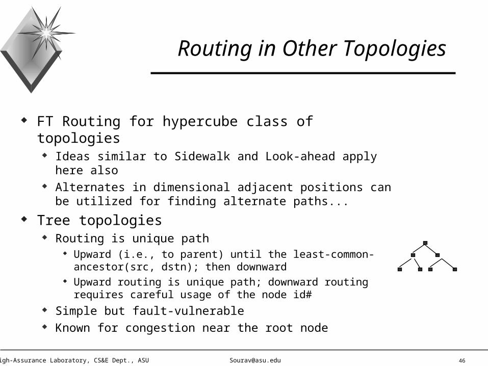
Routing in Other Topologies
FT Routing for hypercube class of topologies Ideas similar to Sidewalk and Look-ahead apply here also Alternates in dimensional adjacent positions can be utilized
for finding alternate paths...
Tree topologies Routing is unique path
Upward (i.e., to parent) until the least-common-ancestor(src, dstn); then downward
Upward routing is unique path; downward routing requires careful usage of the node id#
Simple but fault-vulnerable Known for congestion near the root node

47High-Assurance Laboratory, CS&E Dept., ASU [email protected]
Alternate Paths Structure in Various Topologies
n-Cube: n! different (and, n disjoint paths) between any two nodes n-Cube: n edge-disjoint broadcast trees (N, N) mesh: X-Y routing offers plenty of routing alternatives Tree structure: congestion, and fault-vulnerability near the root
Some solutions: Fat tree, X-tree, ... Fat-Tree:
Alternate routes utilize redundant links near the route (CM-5) X-Tree: redundant connection between “first-cousin” leaves
Leaves that have a common level-2 parent, but no direct (level-1) parent

48High-Assurance Laboratory, CS&E Dept., ASU [email protected]
Other Popular Symmetric Topologies
Fat Trees Hypercube-derived topologies
De-Bruijn, Cube-Connected Cycles, Shuffle-Exchange, ...
Mesh derived topologies Spanning bus, 3D mesh, torus (2D mesh with wrap around links)
Summary: Symmetric topologies help But, design of excessively convoluted topologies is not (at least) practical
Literally, thousands of topologies have been designed Only simple ones like 2D mesh are still being used

49High-Assurance Laboratory, CS&E Dept., ASU [email protected]
Routing with Asymmetric Topologies (still !!)
Hierarchical routing Network size scalability lead to vast sized routers Router tables occupy too much space, also large scanning time Graph algorithms, e.g., (all-pair) shortest path finder, sink tree
computation, etc. can lead to state-space explosion...
Multi-level routers Attractive to create multiple clusters of networks, each cluster with
limited size and (hopefully) manageable size of the router tables Each cluster, or sub-cluster, will only have local nodes’ routing
info. Nodes in other regions will be routed via their gateways 2-level routers may be inadequate for very large networks, leading
to multi-level routers
50High-Assurance Laboratory, CS&E Dept., ASU [email protected]
Multi-Level Routers
Gateways Nodes within a particular region or cluster are addressed (from
outside of the cluster) via “gateways” or representative nodes within the cluster. Gateway behaves like a point-of-contact...
Gateway node’s address is externally visible, other node addresses are hidden from outside
Benefit: reduced complexity @ router tables Disadvantage: extra load at the Gateway; liklely creation of hot-spot
at the Gateway, path lengths can become longer, etc.
Example: refer Figure 5-17(b) in Text Benefit: router table is reduced Another disadvantage: path length may get elongated

51High-Assurance Laboratory, CS&E Dept., ASU [email protected]
Mobile Nodes
Migrating nodes Node always connect using the static, wired infrastructure But, node can move around in between successive connections
Example: take your laptop to a hotel room, and access Internet Essentially, stationary users who migrate from one fixed site to
another. They use the network only when static and physically connected to the wired network.
Roaming nodes Maintain a connection while on the move (e.g., laptop connected
over a cellular phone) Wireless media usage
Mobile != Wireless

52High-Assurance Laboratory, CS&E Dept., ASU [email protected]
Routing to Mobile Nodes
Home location Every node, static or mobile, has a home location and a home address
Network area An “area” is a LAN, MAN or a wireless cell - to which a node can
connect to at a given point in time Area contains a foreign agent, and a home agent
Foreign agent Keeps track of all the mobile nodes (from other Areas) currently visiting
the local Area
Home agent Keeps track of users whose home is in the local Area, but who are
currently visiting outside

53High-Assurance Laboratory, CS&E Dept., ASU [email protected]
Mobile Routing (contd...)
Mobile node enters a new Area - sequence of events: Register with the local Area’s foreign agent
Push vs. Pull model Informed by the mobile node, or interrogated by the foriegn agent
Local Area’s foreign agent informs the home agent of the mobile host’s home Area
Establish a forwarding address, at the home address
Message for the mobile node arrives at home address Get forwarded to the currently visiting Area Sender notified of the address update Subsequent messages are directly sent to the updated address
Economizes on re-routing effort
54High-Assurance Laboratory, CS&E Dept., ASU [email protected]
Mobile Routing - Design Details
Protocol hosted by routers or by the hosts themselves Intermediate routers can record mapped addresses, and
(subsequently) intercept messages and re-route directly Addressing can be done for each mobile visitor, or for a common
agent that accommodates every visiting node Mechanism of re-routing the message
Re-create the destination address, and send to the updated address Envelope the entire message into a new message, with re-direction address
Security of the address forwarding method How reliable and authentic is this approach ?

55High-Assurance Laboratory, CS&E Dept., ASU [email protected]
Broadcast Routing
Taxonomy of routing Routing: from source to destination # destinations: 1, few, all nodes of the network
1-to-1: routing 1-to-few: multicast 1-to-all: broadcast
#source nodes: 1, few, all Does it make sense ? Each source must send different pieces of information... Leads to “all-to-all Chat”, or “gossip” type of communications
Broadcast routing One node sends a common message to every other node in the system

56High-Assurance Laboratory, CS&E Dept., ASU [email protected]
Broadcast - Needs and Implementation
Applications that require broadcast operations System initialization Reporting common information, e.g., weather, stock market, ... Synchronization messages, etc.
Naive implementation approach Source sends the message to each destination, as a distinct packet Broadcast implemented as a (large) collection of routing
operations Simple, but wasteful of routing efforts and bandwidth Should be adopted only when none other works !!

57High-Assurance Laboratory, CS&E Dept., ASU [email protected]
Broadcast Implementation
Flooding May not be as bad, as it would for routing
(In routing, the flooding approach is an overkill - but may be an ok approach for broadcast)
Yet, flooding is based on point-to-point communications Generates too many redundant packets
Multi-destination routing Construct a set of packets, each packet is responsible for routing to
a selected set of (non-overlapping ?) destination nodes Route each packet as a set of outgoing messages from the current
router, depending on the set of destinations NB: different from distinct route to each destination approach

58High-Assurance Laboratory, CS&E Dept., ASU [email protected]
Broadcast Implementation (contd...)
Spanning tree approach Generalization of the multi-destination routing approach -- a single
packet tagged with all the destination nodes Utilize the sink tree, or any spanning tree rooted at the source node Message is sent along the spanning tree, and replicated at the
intermediate nodes as necessary (per the fan out of the intermediate nodes of the spanning tree)
Economizes bandwidth, and generates a minimized number of packets
Disadvantage: each router must have the entire spanning tree topology information
How expensive it is to create the (best ?) sink tree ? What are the criteria for “best” ? Hops ? Delay ? Total traffic ?
59High-Assurance Laboratory, CS&E Dept., ASU [email protected]
Spanning Tree Approximation
Reverse Path Forwarding Essentially, a (very) selective flooding approach If the incoming packet (to an intermediate router) arrives on the
“desired” path - then flood the packet Else, discard the packet Criterion for “desired” = same path for sending a reverse packet back
to the source of the broadcast Generates a good approximation of a spanning tree, without
having to compute the entire spanning tree Each node only needs to remember the desired link/port# to every
other node in the network
Example: Figure 5-20 The reverse path forwarding tree is created per the sink tree rooted
at the source node of the broadcast

60High-Assurance Laboratory, CS&E Dept., ASU [email protected]
Multicast Routing
Often more complex than implementing Broadcast Multicast is to a group of nodes, so management of the
node-groups is needed Group naming, and re-naming Nodes join and leave multicast groups
Spanning tree based multicast implementation Similar to broadcast, but on a selected set of destinations Tradeoff issues in each router having to know the multicast
spanning tree
Metrics of multicast Total traffic generated and the “time” consumed
61High-Assurance Laboratory, CS&E Dept., ASU [email protected]
Multicast Routing (contd...)
Spanning tree generation Using Link-State Routing Using Distance Vector routing Continuous updates to the network status by “probe” messages Disadvantage: large # of spanning trees, to be pre-computed
Multicast with symmetric topologies Spanning tree generation becomes much simpler Well-known multicast tree generation algorithms for mesh,
hypercube, hypercube-derived networks etc Results from parallel arch. area apply to the networks area
62High-Assurance Laboratory, CS&E Dept., ASU [email protected]
Multicast - A Better Treatment
Multicast Objectives Generate a spanning tree, rooted at the source node and leaves as
the destination nodes For dependability purposes, the multicast tree may be augmented to
contain cycles Intermediate nodes may be destination nodes, or simply forwarding
nodes Protocol should support replicating the message stream at the
intermediate nodes
Multicast Metrics Traffic = total number of tree edges Time = delay from the source to the destinations
Delay measured as hops, time delay, ... Max delay, or average delay, or ??

63High-Assurance Laboratory, CS&E Dept., ASU [email protected]
Centralized Multicast vs. Distributed Multicast
Centralized Approach: the source (or, some centralized) node computes the entire
multicast spanning tree Topology: known, for symmetric topologies
For asymmetric topologies: periodic (or, event driven) update of the connectivity pattern
Link load levels: periodic (or event driven) update - required for both symmetric and asymmetric topologies
Global update required, since any node may be a multicast source
Distributed Approach: compute the multicast spanning tree progressively, at each local
node. Similar features as in distributed routing, besides the tree shape generation issue.
64High-Assurance Laboratory, CS&E Dept., ASU [email protected]
Centralized vs. Distributed Multicast Tree - Tradeoff
Quality of the spanning tree Centralized: can typically do better Distributed: performs reasonable for symmetric topologies, otherwise not
very good
Overhead (status updates) Centralized: usually higher, since every nodes has to get a global status of
the entire network Distributed: usually less, unless trying for a (near) optimum multicast tree
Overhead (algorithm execution) Either of the approaches, if trying for a (near) optimum tree ==> may require
exponential complexity Usually, distributed algorithms are simpler/quicker to execute

65High-Assurance Laboratory, CS&E Dept., ASU [email protected]
Special Project
Input A 2-Dimensional mesh with 16x16 nodes. Each point-to-point link delay = 1 unit.
A source node, without loss of generality, at (0, 0) Couple of destination nodes, say 6 destination nodes spread across the mesh. NB:
the destination nodes could be anywhere, do not make any assumptions about their positions
No other traffic in the mesh topology
Goal: generate the minimum traffic multicast tree Traffic = total number of mesh links on which you allocate multicast tree edges
Question: what is the time complexity of such a traffic minimized multicast tree generation ? (2 absolute points) Provide a proof, as a basis for your answer (2 absolute points)
66High-Assurance Laboratory, CS&E Dept., ASU [email protected]
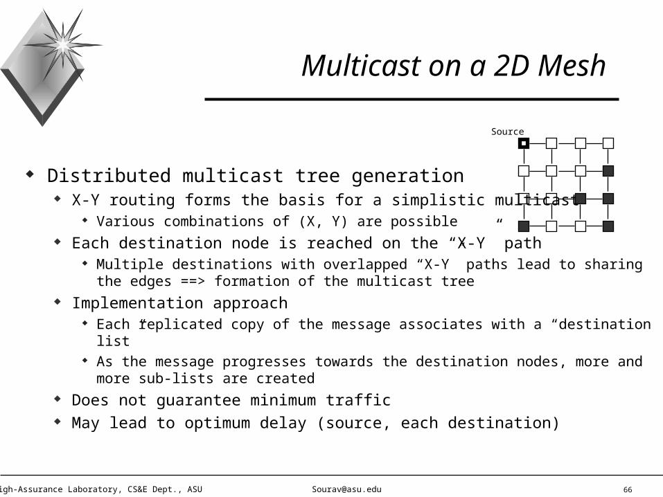
Multicast on a 2D Mesh
Distributed multicast tree generation X-Y routing forms the basis for a simplistic multicast
Various combinations of (X, Y) are possible Each destination node is reached on the “X-Y” path
Multiple destinations with overlapped “X-Y” paths lead to sharing the edges ==> formation of the multicast tree
Implementation approach Each replicated copy of the message associates with a “destination list” As the message progresses towards the destination nodes, more and
more sub-lists are created Does not guarantee minimum traffic May lead to optimum delay (source, each destination)
Source

67High-Assurance Laboratory, CS&E Dept., ASU [email protected]
Multicast on a Hypercube
Optimum traffic multicast tree generation is harder, than for mesh A simple, distributed multicast approach
Based on e-cube routing (analogous to the X-Y routing for mesh) Variations in dimension ordering can lead to different multicast trees A particular dimension ordering, once chosen, is adopted at all the intermediate
router nodes Each destination node is reached following the e-cube routing path, with the
adopted dimension ordering Implementation approach: message replication, and destination list partitioning
(analogous to that for 2D mesh)
Centralized multicast: shortest neighbor approach Message reached cluster, and computation of least cost neighbor to the
cluster, in each step. Repeat until all destination nodes reached.

68High-Assurance Laboratory, CS&E Dept., ASU [email protected]
Efforts in Internet Multicast, and Wireless Multicast
Focuses on layers above and beyond the Network Layer Orthogonal to the level of our interest No effort in traffic optimization at the spanning tree generation level Notion of “congestion control”, “traffic optimization” etc are used in
context of address group/list management sense Notion of “real-time” is in the context of OSI stacks’ delay, and not in path
length minimization Reflects the culture difference between architecture, and networks areas...
Wireless Multicast Intra-cell: spanning tree generation within a cell, current work is mostly in
address group management Inter-cell: wide open area, addressed for base-stations oriented systems only

69High-Assurance Laboratory, CS&E Dept., ASU [email protected]
Congestion Control
Critical for management of a number of users on the network Cost, utilization and co-operation requirements prohibit single user networks !!
One has to live with networks that can have other users’ traffic as well. Differs from flow control, which is a single (src, dstn) node pair’s concern
Congestion control is a network wide concern, which may (incidentally) be applied to individual (src, dstn) node pairs as well
Congestion avoidance - illusions Provide more buffer space at the routers - it does not work Make the links higher bandwidth - it helps, but certainly is not a total solution
Two types of solutions Open loop congestion control Close loop (i.e., feedback oriented) congestion control

70High-Assurance Laboratory, CS&E Dept., ASU [email protected]
Congestion Generation Factors
Bursty transmission behavior of the node(s) Fact of life, some nodes will always transmit bursty
Limited memory buffer @ Routers Unlimited memory - does it help ? No, since the (long) queue delay leads to likely re-transmission
and much increased traffic
Slow processors Unable to drain out the receiving buffer fast enough
Lower bandwidth lines, and higher bandwidth users Disparity between producer/consumer lines

71High-Assurance Laboratory, CS&E Dept., ASU [email protected]
Open Loop Congestion Control
Open loop approach: Admission or Rate Control Network is treated as a fenced territory Admission of any new traffic is decided on a case by case basis
Somewhat like the “schedulability” criterion in real-time system Admission criteria should include the expected load, as well as duration of the
connection De-admission, or discarding policies may be adopted
A message, once included (i.e., start to be transmitted), may be allowed to be interrupted
Leads to the (currently very active research) area of QoS negotiation Instead of discarding a channel, one may negotiate its bandwidth, or in general the
Quality of Service parameters
Design question: admission control @ each hop, or end-to-end ? At source, or destination, or ??
72High-Assurance Laboratory, CS&E Dept., ASU [email protected]
Closed Loop Congestion Control
Feedback approach Open loop approach + information fed back from monitoring
Metrics for monitoring Percentage of discarded packets
Due to lack of buffer Due to exceeding the time deadline
Average queue length Average (or, max ?) packet delay
Feedback propagation scheme Sent to every node, or the source nodes only ? Source of one message, or each message ?

73High-Assurance Laboratory, CS&E Dept., ASU [email protected]
Feedback Propagation (contd...)
Means of feedback propagation As distinct messages, but this will create additional traffic overhead As flags, or bit-fields attached to other messages
Slower way of notification, instead of immediate notifications Pull model, instead of Push
Routers send periodic probe messages to solicit network congestion status Implicit feedback: source observes local effects to infer about congestion
Feedback control algorithm If congested, reduce traffic input @ source node(s), or increase resource Simple, but requires added sophistication to implement
Time granularity of correction: too soon, or too slow Stability of the feedback control algorithm is critical to observe
74High-Assurance Laboratory, CS&E Dept., ASU [email protected]
Feedback Control (contd...)
Increase the line capacity Start using the backup links (perhaps designed for added reliability) Subscribe to additional line resources (how soon can this be done ?) Re-adjust the bandwidth partitions between multiple groups
Applications in secure networks Increase transmission power (for wireless systems), to avail additional
line bandwidths
Decrease the user (traffic) loads Deselect existing channels Negotiate the bandwidth (QoS) of existing channels Consider alternate routing styles
Eliminate hot spots
75High-Assurance Laboratory, CS&E Dept., ASU [email protected]
Policies that affect Congestion Prevention
Re-transmission Time-out parameter: how soon to re-transmit ? Caching of out-of-order packets: how early to discard “suspected out-
of-order” packets ?
Acknowledgement: Granularity of Ackn (viz. extra traffic) Flow Control: tighter flow control (smaller window) reduces
congestion Routing algorithm: reduction/avoidance of hot spots Packet Management: service discipline
Queueing, scheduling, and discarding policies
Refer Fig. 5-23, in Text

76High-Assurance Laboratory, CS&E Dept., ASU [email protected]
Traffic Shaping
Reduction of burstiness ==> congestion control Bursty, unsteady traffic ==> smooth, uniform rate of bit-flow Leads to predictability, a more accountable environment for traffic
management Two popular approaches to traffic shaping
Leaky bucket Token bucket
Leaky bucket Popular approach (ATM) for statistical MUX Refer Figure 5-24, in Text (Question: there is a major difference,
though ! What is it ?) Bucket characteristics: Bucket capacity, and diameter of the hole

77High-Assurance Laboratory, CS&E Dept., ASU [email protected]
Leaky Bucket in Traffic Shaping
Bursty input arrival, initially accommodated in the bucket Bucket output, at a steady rate (viz. the diameter of the
hole), empties the incoming packets/cells Features
Effect of averaging between input rate and output rate Accommodate input burstiness
Statistical MUX Maintains RT deadlines when input rate = output rate
Thus, usage of bucket may not necessarily hurt RT deadline
Disadvantage (any ?) RT deadline may be hurt, if a constant queue length is maintained

78High-Assurance Laboratory, CS&E Dept., ASU [email protected]
Token Bucket in Traffic Shaping
Generate somewhat more bursty traffic than Leaky Bucket Bucket generates a token per a fixed time interval
Arriving packets need one token each to be output After transmission, the particular token used for transmission is
destroyed
Distinction from leaky bucket Token bucket can hold upto N packets, N being as large as the
bucket size Creation of localized burstiness - explain why ? Variability in the output rate Explain Figure 5-25, in Text
Never a lost packet (at the bucket) - why ? (Its a bucket of tokens !)

79High-Assurance Laboratory, CS&E Dept., ASU [email protected]
Leaky Bucket vs. Token Bucket
Bucket with packets Width of the “leak” or hole in the
bucket Smoothed traffic output
Likely loss of packets, when buffer overflow occurs
Priority implementation ??
Dynamic control of the width of the “leak”
Bucket with tokens Token generation rate
Local burstiness, overall smooth nature
Claims to be lossless with regards to packets ??
Easy support for priority, and RT traffic
Token fragmentation and micro-management of packets

80High-Assurance Laboratory, CS&E Dept., ASU [email protected]
Leaky Bucket with Token Bucket
Explain Fig. 5-25 (c) Would you use ?
Leaky Bucket, followed by Token Bucket Under what circumstances and with what feature expectations ?
Or, Token Bucket, followed by Leaky Bucket
What happens if one joins different policies (for different VCs, of course) at a particular switch port ?

81High-Assurance Laboratory, CS&E Dept., ASU [email protected]
Flow Specification
Traffic shaping is best used when Sender characterizes the flow patterns Receiver realizes whats going to come Network agrees to ship the packets without fail
Need to be able to specify the Flow Pattern
Input characteristics Maximum packet size (how about avg and std. deviation ?) Maximum transmission rate (from the sender)
Average and other measures also apply Traffic shaping related:
Token bucket size, fill-up rate (in bytes)

82High-Assurance Laboratory, CS&E Dept., ASU [email protected]
Applications’ QoS
Is my data reaching to the destination correctly ? If not, maximum loss rate minimum interval between successive packet/cell drops maximum allowable burst error (sequence) length
Other features: Isochronous:
Max, and min. delay between successive packets(important for Multimedia applications)
Jitter, as a measure of the degree of variability Timing deadline, w.r.t. RT properties Security, and just about every other attribute of interest Textual interpretation of “QoS”
83High-Assurance Laboratory, CS&E Dept., ASU [email protected]
Flow Specification vs. Guarantees
Once specified, will it be honored ? Various guarantee modes:
Non-expulsion guarantee - Once admitted, the VC will be serviced without expelling However, its QoS may not be strictly followed
QoS satisfying guarantee As long as the VC is being serviced, all the QoS parameters will be
strictly followed However, the VC may altogether get preempted (i.e., killed)
Types of guarantees: Hard guarantees - “yes” means 100% true, and always Soft guarantees - best effort approach
84High-Assurance Laboratory, CS&E Dept., ASU [email protected]
Congestion Control in Virtual Circuits
Admission control over multihop networks Resource must be adequate along each hop of the VC’s path Implementation approach:
Sequentially, check the resource availability along each link Issue: staleness of the information Solution: 2PL - place a reservation on the forward path, and confirm the
entire path’s availability during the return path Question: deadlock possibility ?
When admission control phase fails to allocate a multihop VC: Explore additional resource via different routing paths Negotiate Quality of Service for the existing VCs, or the freshly
requested one
85High-Assurance Laboratory, CS&E Dept., ASU [email protected]
Congestion Control with Single Packets
Simpler problem than Congestion Control with Multiple Packets Applicable both for VCs (with de-regulated packets) or datagrams
Choke Packets A congested link, L, (reaching above a certain utilization level) realizes the
“warning” - that it is heading to a problem (in near future !!) L sends “choke” packets to the source(s) of message(s) passing through L When the respective source node(s) receive a “choke” packet
Source node decreases the traffic flow rate, i.e., reduces the #packets/sec Hopefully, L can get out of the “warning” states
(Relate this to your Project II) Choke packets are identified using the (src, dstn) id-pair Choke must be implemented with a Time-out, beyond which multiple
“choke”-based restraints can occur ==> incremental feedback & control

86High-Assurance Laboratory, CS&E Dept., ASU [email protected]
Choke Packets (contd...)
Choke packet across a multihop path ==> long choke length Longer than desired feedback control delay, i.e., sluggish Solution: choke hop by hop Issue: Message flow control per hop - is this realistic ?
Yes, for long-haul networks with large router delays Otherwise, its impractical to implement
Disadvantage of Choke Packets Assumption: Every source node plays a fair game, i.e., once told to
slow down - they will indeed slow down If violated, Choking approach can become
Ineffective Unfair to the honest source nodes, i.e., the ones who listens to choking
87High-Assurance Laboratory, CS&E Dept., ASU [email protected]
Queueing Algorithms for Congestion Control
Fair Queueing Routers have multiple queues, one for each output line Arriving packets queue up at the respective buffers Service policy: Round robin
Used in some ATM switches Disadvantage: non-uniform packet size leads to unfairness
Service policy: Byte-by-byte round robin Used in many other ATM switches Refer Figure 5-29, in Text
Weighted Fair Queueing Assign priorities to the different Queues, giving preferential
treatment to some channels over the others...

88High-Assurance Laboratory, CS&E Dept., ASU [email protected]
Load Shedding
Adopted when none of the congestion control techniques work (the traffic is too large, compared to the bandwidth)
Approach: drop packets, but how ? Randomly - most naive approach Drop older (time) packets - e.g., multimedia packets/cells Drop newer (time) packets - e.g., for FTP and any application that
cannot afford to miss any packet, requiring re-transmission Also, depends on the nature of the re-transmission protocol
Under various packet-coding policies Drop differential packets, if the protocol sends “essential” and
“differential” packet formats
89High-Assurance Laboratory, CS&E Dept., ASU [email protected]
Selective Packet Dropping Policies
Routers can drop packets more intelligently, if users/applications mention which packets are more (or, less) important Applications must mark which packets are important Prioritize the packets
Group 1: Very important, never drop this packet Group 2: Moderately important, don’t drop if you can... Group <last>: Least important, drop if you have anything (else) better to send
Incentive Policies What prevents an application to state that everyone of its packets are of the highest
priority level ? Pricing incentive: the higher the priority, the more the user pays (per packet) Alternate approach: Traffic beyond the negotiated bandwidth is lower priority traffic

90High-Assurance Laboratory, CS&E Dept., ASU [email protected]
Jitter and Jitter Control
Desired features in a multimedia stream Isochronous: inter-packet arrival time must be nearly consistent (e.g.,
successive frames of a live video stream) Synchronized: Video, voice, caption etc. traffic cells must arrive together
at the receiver stations Selection of alternate routes for different traffic types ==> likely variations of
path delays
Jitter Control Approach Each packet is time-stamped, with respect to its (time) peers Policy @ each router:
If a packet is ahead of schedule, buffer & delay it until it follows the schedule If a packet is behind schedule, then rush its delivery
91High-Assurance Laboratory, CS&E Dept., ASU [email protected]
ATM Layer
Network Layer in ATM Networks OSI layer positioning of ATM Layer ?
Data Link Layer or Network Layer ? Arguments in favor of Network Layer
Multiple hops, routing and switching across the net Global addressing, reasonably reliable
Arguments against Network Layer Can port IP on top of ATM, making ATM look like Data Link Layer In LAN emulation, the multihop-VCs are treated as a logical single hop
link, and thus like the Data Link Layer
ATM Nuggets - what’s really new ? Statistical MUX Scalability and hierarchical path (VP and VC) routing
92High-Assurance Laboratory, CS&E Dept., ASU [email protected]
Attributes of ATM Connections
Connection oriented protocol Both in service to the users, as well as in the internal operations
(Thus, it is not simply emulating a Connection-Oriented circuit.) But, no explicit Ackn signals
Designed primarily for highly reliable media, e.g., Optical Ackn is probably not much use for real-time, isochronous traffic
Basic element is a “connection”, called as Virtual Channel 2-level connection hierarchy Connection is implemented by a virtual circuit (VC)
VCs are simplex, but back-to-back VCs (not necessarily same QoS) can make duplex links
A bundle of VCs form a virtual path (VP)
Cell delivery order guarantee within each VC
93High-Assurance Laboratory, CS&E Dept., ASU [email protected]
Cell Layout
48 byte Payload + 5 byte header (Figure 5.62) Header (error handling, priority, flow control, path id#, network
management) 16 bit VCI 8 or 12 bit VPI (4 bit for Flow Control, with host to network interface) 3 bit PTI (payload type), Figure 5-63
Combines user supplied data type, with network management functions 1 bit CLP, or cell priority - used for cell overflow policy dictator
Certainly, not enought for multi-priority applications 8 bit error code over the header only, not on the payload
Code to correct all single bit errors, and most multibit errors

94High-Assurance Laboratory, CS&E Dept., ASU [email protected]
VPI vs. VCI
ATM enforces a 2-level hierarchical path id#: (VP, VC) 1-level path id# can land up spending a lot of computing time at each
intermediate switch to identify which output line to select for each cell 2-level path id# can reduce this overhead (example: US Mail routing) Only VPI field is used for switch to switch routing VCI field is used for (switch, host) or (host, switch) routing
VCI: The first and the last hop VPI: Remaining hops
Benefits of 2-level hierarchical path id# Once a VP has been setup, it offers a common highway for a varying number of
VCs to be established between source and destination. No fresh routing decision needs to be made.
Simplified routing decision, since routing occurs within a common VP. Smaller lookup table.

95High-Assurance Laboratory, CS&E Dept., ASU [email protected]
Routing and Switching of VCs
Benefits of VP (contd.) Rerouting of VCs (clustered within a VP) becomes simpler
One operation, instead of having to reroute all the VCs individually Easier establishment of private (“closed door”) networks. A VP can offer the
look and feel of a private intra-net.
VCs clustered within VPs (Switch VC, vs Permanent VC) Switching @ Intermediate nodes
Each intermediate switch maintains a VPI-to-output link mapping index or table Table is initiated when the switch boots up Table is updated as each VP (and, VC) gets setup Example: Figure 5-67 and Figure 5-68 (NB: both figures are for one switch.) Routing decision: (outgoing line, outgoing VPI) = table(incoming line, in VPI)

96High-Assurance Laboratory, CS&E Dept., ASU [email protected]
Connection Setup
Create a Connection = (acquire a connection, then use it) Acquire a VC - how ? Send a VC-setup request on a pre-existing (network management VC)
VP=0, VC=5 ==> used for opening such new virtual circuits Benefit of the 2-step process for VC setup: dynamic allocation of the
bandwidth, the pre-existing VC can be of very low (and, always alive) bandwidth. Other VCs are created as and when needed.
Alternate approach: Permanent VC or PVC Static load, but no setup time required
Connection setup across a multihop VC (Figure 5-65) Six types of messages, each with a specific request or ackn role No end-to-end Ackn, all ackn signals are within physical hops neighbors only

97High-Assurance Laboratory, CS&E Dept., ASU [email protected]
Connection Release
Protocol description Uses two of the six message types (Figure 5-64) Standard handshake technique between adjacent switches/nodes
Refer Figure 5-65(b) Delay in Setup
Round trip delay of the “Setup Request” and “Connect” confirmation 1-neighbor ackn signals do not add to the total delay
Delay in Release Forward trip delay of the “Release Request” only 1-neighbor ackn signals do not add to the total delay
Why ATM does not have explicit end-to-end ackn signals ?

98High-Assurance Laboratory, CS&E Dept., ASU [email protected]
Service Categories
Five Classes of Services provided to the traffic Constant Bit Rate (CBR) Variable Bit Rate (VBR)
With hard real-time requirements With near (soft) real-time approach (i.e., jitter allowed)
Available Bit Rate (ABR) Best effort approach, with traffic load which may be bursty and whose
average load is approximately known Unspecified Bit Rate (UBR)
No guarantee, no feedback about congestion Cells may simply drop, without any notification Ideal for sending IP packets, since IP makes no promise about delivery
Cheapest service: UBR
99High-Assurance Laboratory, CS&E Dept., ASU [email protected]
Service Categories (contd.)
Examples CBR: uncompressed live video with strict isochronous requirement VBR (real-time): real-time videoconferencing with compression VBR (non real-time): soft real-time videoconferencing with compression ABR: read email, browse web, airline reservation, ... UBR: background ftp
Service Characteristics Bandwidth guarantee: Available for CBR, VBR, and optionally for ABR RT Traffic support: only CBR, and VBR (real-time) Bursty Traffic support: for VBR (non real-time), ABR and UBR Congestion feedback: only in ABR

100High-Assurance Laboratory, CS&E Dept., ASU [email protected]
Quality of Service
Reflection of the contract between the customer (src, dstn) and the network
QoS allows one to setup the contract in firm grounds QoS parameters include (refer Figure 5-71)
Cell rate (peak, sustained, minimum) Cell delivery delay (mean delay, variation, maximum tolerance) Cell loss ratio (fraction of cells lost or delivered beyond deadline) Cell error rate (fraction of cells delivered without any error in
them) others...