1 exam 1 review chapters 1, 2, 9. 2 charge, q recall coulomb’s law unit: newton meter 2 / coulomb...
TRANSCRIPT

1
Exam 1 Review
Chapters 1, 2, 9

2
Charge, qRecall Coulomb’s Law
1 21 122
0 12
1
4
q q
rF e
7 2 9
0
110 8.99 10
4c
Unit: Newton meter2 / coulomb2
volt meter / coulomb
Charge on an electron (proton) is negative (positive) and equal to 1.602 x 10⁻¹⁹ C
12 1 2distance between charge and r q q
Force F1 on charge q2 due to charge q1 is given by
12 1 2unit vector pointing from to q qe
Note: Positive force is repulsive, negative force is attractive
1q
2q
12r
12e

3
Electric Current, i
Current (in amperes) (A) is the time rate of change of charge q
dqi
dt 1 A = 1 C/s
00( ) ( )
t
tq t idt q t
0
( )t
T tq t idtCharge flowing past a point in the interval [t0, t] is
Convention: Direction of current flow is that of positive charges, opposite to the direction of electron flow

4
VoltageThe energy in joules (w) required to move a charge (q) of one coulomb through an element is 1 volt (V).
dwv
dq
1 volt = 1 joule/coulomb = 1 newton meter/coulomb

5
Power and Energy
Power (p), in watts (W), is the time rate of expending or absorbing energy (w) in joules
dwp
dt
dw dw dqp vi
dt dq dt

6
Power and Energy
2 2
1 1
t t
t tw pdt vidt
Change in energy from time t1 to time t2
Passive sign convention:
+
-
( )i t
p viIf p > 0 power is absorbed by the element
If p < 0 power is supplied by the element
( )v t

7
Ohm's Law
v iR vi
R
Units of resistance, R, is Ohms ()
vR
i
R = 0: short circuit :R open circuit
1v i R 1( )i i
Ri
+ -
v+ -
R i
v+ -
1
8
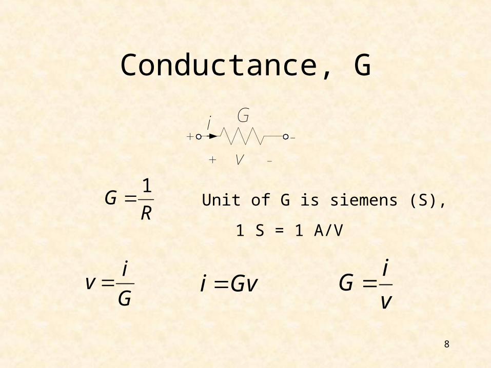
Unit of G is siemens (S),
Conductance, G
1G
R
iv
G i Gv
iG
v
1 S = 1 A/V
Gi
+ -
v+ -

9
Power
A resistor always dissipates energy; it transforms electrical energy, and dissipates it in the form of heat.
Rate of energy dissipation is the instantaneous power2
2 ( )( ) ( ) ( ) ( ) 0
v tp t v t i t Ri t
R
22 ( )
( ) ( ) ( ) ( ) 0i t
p t v t i t Gv tG

10
Elements in Series
Two or more elements are connected in series if they carry the same current and are connected sequentially.
V0
I
R1
R2

11
Elements in Parallel
Two or more elements are connected in parallel if they are connected to the same two nodes & consequently have the same voltage across them.
VR1
I
R2
I1 I2

12
Kirchoff’s Current Law (KCL)
The algebraic sum of the currents entering a node (or a closed boundary) is zero.
1
0N
nn
i
where N = the number of branches connected to the node and in = the nth current entering (leaving) the node.

13
1
0N
nn
i
1i
5i
2i
3i
4i
Sign convention: Currents entering the node are positive, currents leaving the node are negative.
1 2 3 4 5 0i i i i i

14
Kirchoff’s Current Law (KCL)
The algebraic sum of the currents entering (or leaving) a node is zero.
1i
5i
2i
3i
4i1 2 3 4 5 0i i i i i
1 2 3 4 5 0i i i i i
The sum of the currents entering a node is equal to the sum of the currents leaving a node.
1 2 4 3 5i i i i i
Entering:
Leaving:
15
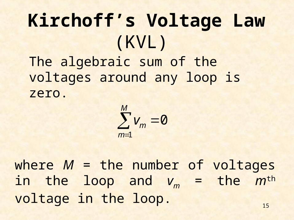
Kirchoff’s Voltage Law (KVL)
The algebraic sum of the voltages around any loop is zero.
1
0M
mm
v
where M = the number of voltages in the loop and vm = the mth voltage in the loop.

16
Sign convention: The sign of each voltage is the polarity of the terminal first encountered in traveling around the loop.
The direction of travel is arbitrary.
Clockwise:
Counter-clockwise:
0 1 2 0V V V
2 1 0 0V V V
0 1 2V V V
V0
I
R1
R2
V1
V2
A +
+
-
-

17
0 1 2 1 2V V V IR IR
1 2I R R
sIR
1 2sR R R
Series Resistors
V0
I
R1
R2
V1
V2
A +
+
-
-
VR
I
s
18
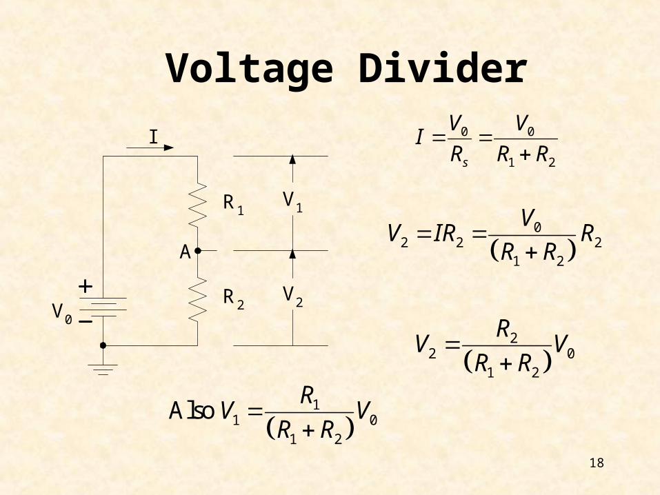
V0
I
R1
R2
V1
V2
A
Voltage Divider0 0
1 2s
V VI
R R R
0
2 2 21 2
VV IR R
R R
2
2 01 2
RV V
R R
1
1 01 2
Also R
V VR R
19
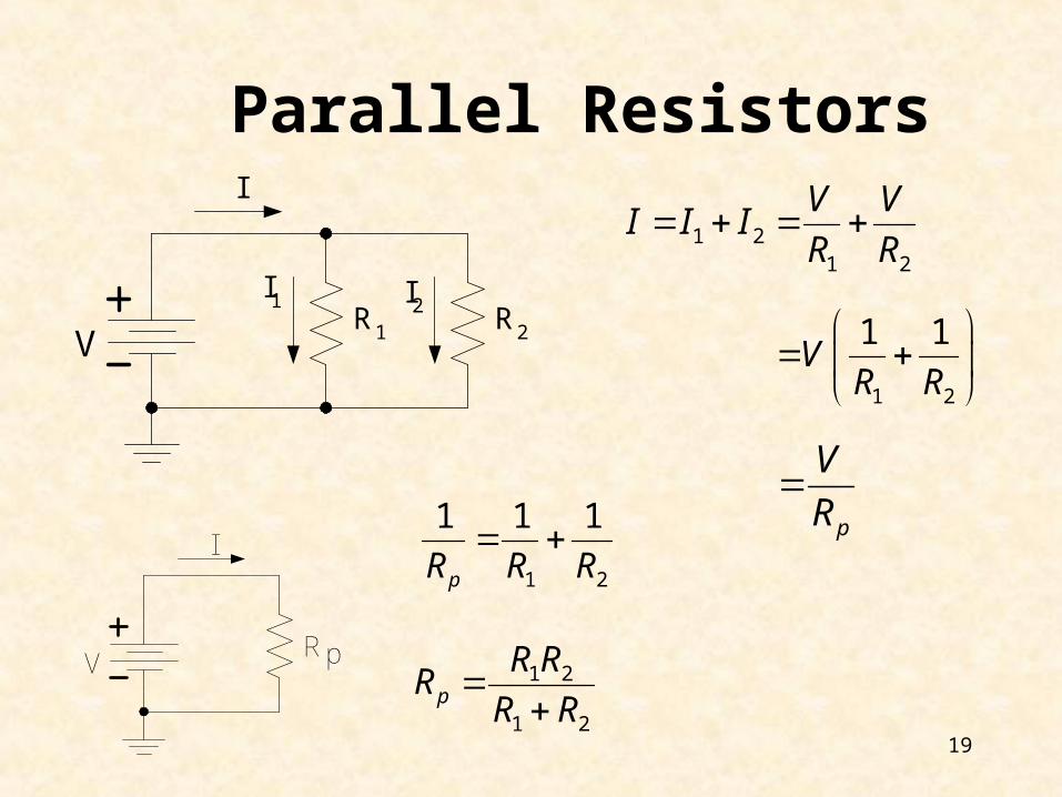
VR1
I
R2
I1 I2
1 21 2
V VI I I
R R
Parallel Resistors
1 2
1 1V
R R
p
V
R
1 2
1 1 1
pR R R
1 2
1 2p
R RR
R R
V
R
I
p

20
Current Division
i(t) R1
i
R2
i1 i2 v(t)
+
-
1 2
1 2
( ) ( ) ( )p
R Rv t R i t i t
R R
21
1 1 2
( )( ) ( )
Rv ti t i t
R R R
12
2 1 2
( )( ) ( )
Rv ti t i t
R R R
Current divides in inverse proportion to the resistances

21
Current Division
N resistors in parallel
1 2
1 1 1 1
p nR R R R ( ) ( )pv t R i t
( )( ) ( )p
jj j
Rv ti t i t
R R Current in jth branch is

22
Source Exchange
DCsv
sRabv
+
-
abv
+
-
sRs
s
v
R
ai 'ai
We can always replace a voltage source in series with a resistor by a current source in parallel with the same resistor and vice-versa. Doing this, however, makes it impossible to directly find the original source current.

23
Source Exchange Proof
Voltage across and current through any load are the same
DCsv
sRLv
+
-
+
-
sRs
s
v
R
ai 'ai
LRLRLv
L
L ss L
Rv v
R R
s
as L
vi
R R
' s s
a as L s
R vi i
R R R
' L
L a L ss L
Rv i R v
R R

24
B0
B1V1
V0
IB0
IB1 IV1
IV0
2
21
2
B2 V2
2
1 IV2
IB2
3-bit R2-R Ladder Network
0 0 1V B VI I I
0 0 0 1 0
2 2 1
V B V V V
0 0 0 1 02 2V B V V V
0 0 1
12
2V B V
KCL

25
B0
B1V1
V0
IB0
IB1 IV1
IV0
2
21
2
B2 V2
2
1 IV2
IB2
1 1 2V B VI I I
1 0 1 1 2 1
1 2 1
V V B V V V
1 0 1 1 2 12 2 2 2V V B V V V
1 0 1 1 1 2 1
12 2 2
2V B V B V V V
0 0 1
12
2V B V
1 0 1 2
1 12
4 2V B B V
KCL

26
B0
B1V1
V0
IB0
IB1 IV1
IV0
2
21
2
B2 V2
2
1 IV2
IB2
2 2V BI I
2 1 2 2
1 2
V V B V
2 1 2 22 2V V B V
1 0 1 2
1 12
4 2V B B V
2 0 1 2 2 2
1 12
4 2V B B V B V
2 0 1 2
1 1 1
8 4 2V B B B
KCL

27
Table 11.1 Output of R2-R ladder network in Fig. 11.6
B2 B1 B0 V2 0 0 0 0 0 0 1 1/8 0 1 0 1/4 0 1 1 3/8 1 0 0 1/2 1 0 1 5/8 1 1 0 3/4 1 1 1 7/8
2 0 1 2
1 1 1
8 4 2V B B B
B0
B1V1
V0
IB0
IB1 IV1
IV0
2
21
2
B2 V2
2
1 IV2
IB2

28
Writing the Nodal Equations by Inspection
1 2 2 1
2 2 3 4 3 2
3 3 5 3
0 2
0
0 s
G G G v
G G G G G v
G G G v i
2A1R
2R 3R
4R 5Rsi
1v 2v 3v
1i 3i 5i
•The matrix G is symmetric, gkj = gjk and all of the off-diagonal terms are negative or zero.
The ik (the kth component of the vector i) = the algebraic sum of the independent currents connected to node k, with currents entering the node taken as positive.
The gkj terms are the negative sum of the conductances connected to BOTH node k and node j.
The gkk terms are the sum of all conductances connected to node k.

29
•The matrix R is symmetric, rkj = rjk and all of the off-diagonal terms are negative or zero.
Writing the Mesh Equations by Inspection
2
1
1
1 5 7 7 5 1
7 2 6 7 6 2
5 3 5 3
6 4 6 8 4
0
00
0 0
0 0
s
s
s
VR R R R R i
R R R R R i
VR R R i
R R R R i V
The vk (the kth component of the vector v) = the algebraic sum of the independent voltages in mesh k, with voltage rises taken as positive.
The rkj terms are the negative sum of the resistances common to BOTH mesh k and mesh j.
The rkk terms are the sum of all resistances in mesh k.
DC
DC
1R
3R5R
7R
2R
6R
8R
4R
1v 2v
3v 4v
5v6v
7v
8v
+ +
+ +
++
+
+
-
-- -
-
-
-
-
1sV
2sV 1i 2i
3i 4i

30
Turning sources off
a
b
sisi i
Current source:
We replace it by a current source where 0si
An open-circuit
Voltage source:
DC
+
-
sv vsv
We replace it by a voltage source where 0sv
An short-circuit
i

31
Thevenin's Theorem
LinearCircuit
b
a
inR
LR
i
DC
b
a
inR
LR
iThR
ThV
Thevenin’s theorem states that the two circuits given below are equivalent as seen from the load RL that is the same in both cases.
VTh = Thevenin’s voltage = Vab with RL disconnected (= ) = the open-circuit voltage = VOC

32
Thevenin's Theorem
LinearCircuit
b
a
inR
LR
i
DC
b
a
inR
LR
iThR
ThV
RTh = Thevenin’s resistance = the input resistance with all independent sources turned off (voltage sources replaced by short circuits and current sources replaced by open circuits). This is the resistance seen at the terminals ab when all independent sources are turned off.

33
Example
DC 10V
a
b
210V 5V
2 2OC Thv V
DC 10V
a
b
10 2 102.5A
2 3 423
SCi
52
2.5Th
ThSC
VR
i
DC
a
b
5VThV
2ThR
a
b
2 21 2
2 2ThR
34
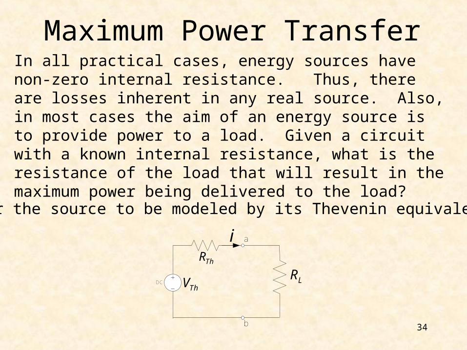
Maximum Power Transfer
In all practical cases, energy sources have non-zero internal resistance. Thus, there are losses inherent in any real source. Also, in most cases the aim of an energy source is to provide power to a load. Given a circuit with a known internal resistance, what is the resistance of the load that will result in the maximum power being delivered to the load?
Consider the source to be modeled by its Thevenin equivalent.
DC
b
a
LR
iThR
ThV

35
DC
b
a
LR
iThR
ThV
The power delivered to the load (absorbed by RL) is
22L Th Th L Lp i R V R R R
This power is maximum when
2 32 2 0Th Th L L Th LL
pV R R R R R
R
0Lp R

36
2Th L LR R R
L ThR R
2
maxL Th
Th Th L L R Rp V R R R
2 2max 2 4Th Th Th Th Thp V R R V R
Thus, maximum power transfer takes place when the resistance of the load equals the Thevenin resistance RTh. Note also that
Thus, at best, one-half of the power is dissipated in the internal resistance and one-half in the load.
2 32 2 0Th Th L L Th LL
pV R R R R R
R

37
Ideal Op Amp
1) 0 vv A v v
The open-loop gain, Av, is very large, approaching infinity.
2) 0i i The current into the inputs are zero.
+
-
i
ov
v
vi
DDV
SSV
0SS DDV v V

38
Ideal Op Amp with Negative Feedback+
-ov
v
v
Network
Golden Rules of Op Amps:
1. The output attempts to do whatever is necessary to make the voltage difference between the inputs zero.
2. The inputs draw no current.

39
Non-inverting Amplifier
+
-
1R2R
ivov
v
v oF
i
vA
v
2
1
1oF
i
v RA
v R
1
1 2i o
Rv v v v
R R
Closed-loop voltage gain
40
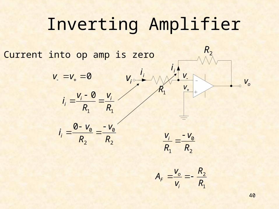
Inverting Amplifier
0v v
1 1
0i ii
v vi
R R
Current into op amp is zero
+
-
1R
2R
ivov
v
vii ii
0 0
2 2
0i
v vi
R R
2
1
oF
i
v RA
v R
0
1 2
iv v
R R