1 erik dick - design of a small hydro kaplan turbine with a self sealing rotor
TRANSCRIPT

FACULTY OF ENGINEERING
Department of Flow, Heat and Combustion Mechanics – www.FloHeaCom.UGent.be
Ghent University – UGent
Design of a small hydro Kaplan turbine
with a self-sealing rotor
S. Annerel, J. Vierendeels, E. Dick
Ghent University
Belgium

Department of Flow, Heat and Combustion Mechanics – www.FloHeaCom.UGent.be
Ghent University – UGent
Overview
• Motivation and initial design
• Sealing rotor
• Rotor flow analysis
• Diffuser flow analysis
• Off-design performance

Department of Flow, Heat and Combustion Mechanics – www.FloHeaCom.UGent.be
Ghent University – UGent
Motivation
• Turbine that can cope with flow rate variation
from design flow rate to zero flow rate
• Needs movable rotor that allows complete sealing
• Like variable opening valve with extraction of power
• Complete flexibility in flow rate
• 6 locations on river Sambre in Belgium
Flow rate: 5.5 m3/s to 20 m3/s
Head: 4.40 m to 1.70 m

Department of Flow, Heat and Combustion Mechanics – www.FloHeaCom.UGent.be
Ghent University – UGent
Initial design
Head (m) 3.60
Flow Rate (m³/s) 16.0
Outer diameter (m) 2.00
Inner diameter (m) 0.80
Rotational speed (rpm) 130
Number of blades 12
Lenght diffuser (m) 4.00
Outlet diameter diffuser (m) 2.75
Shaft power (kW) 395
Total efficiency (-) 0.70

Department of Flow, Heat and Combustion Mechanics – www.FloHeaCom.UGent.be
Ghent University – UGent
Initial design
• Multiple stream tube analysis
‣ Simple radial equilibrium inlet and outlet
‣ No work exchange between streamtubes
‣ Expressed for nine blade sections
• Resulting design:

Department of Flow, Heat and Combustion Mechanics – www.FloHeaCom.UGent.be
Ghent University – UGent
Overview
• Initial design
• Sealing rotor
• Rotor flow analysis
• Diffuser flow analysis
• Off-design performance

Department of Flow, Heat and Combustion Mechanics – www.FloHeaCom.UGent.be
Ghent University – UGent
Obtaining rotor sealingness
• Initial design
‣ Rated flow:
‣ Closed:

Department of Flow, Heat and Combustion Mechanics – www.FloHeaCom.UGent.be
Ghent University – UGent
Means to reach sealingness
• Stacking (lean and sweep) is not efficient
• Solidity distribution: large chord at hub
• Thickness distribution: large thickness at hub
• Camber distribution:
zero camber at hub, large camber at tip
• Untwist rotor: large incidence at hub (10.8˚)
and negative incidence at tip (-2˚)
Department of Flow, Heat and Combustion Mechanics – www.FloHeaCom.UGent.be
Ghent University – UGent
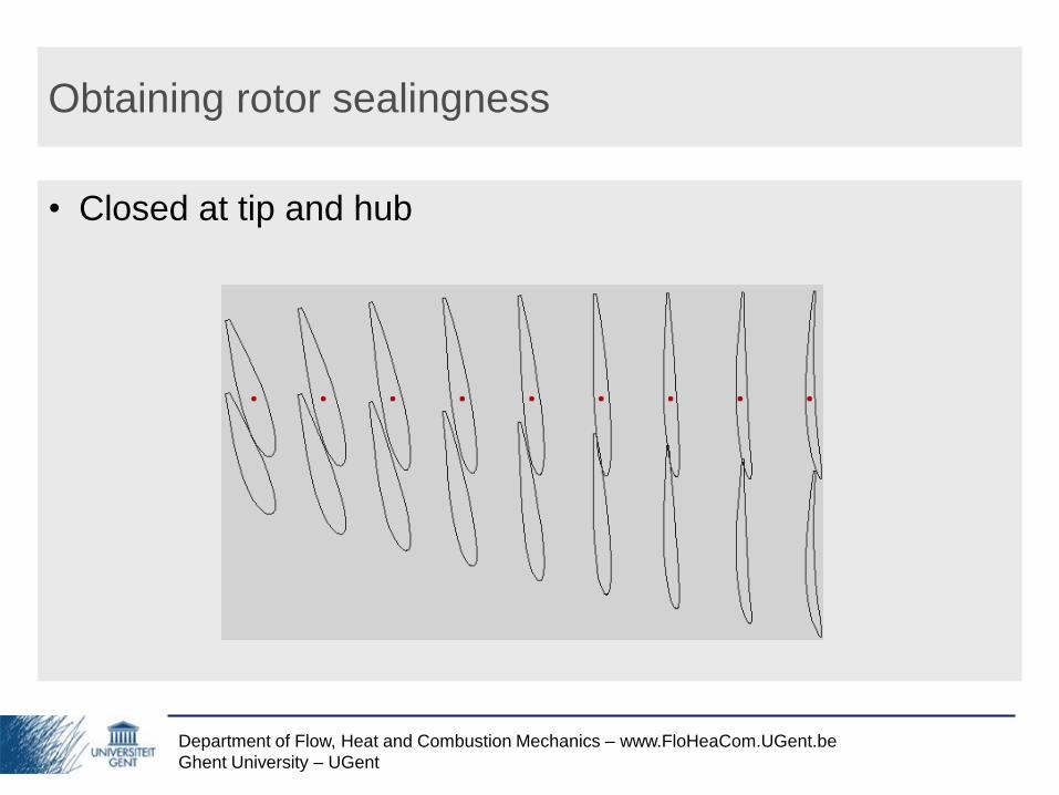
Obtaining rotor sealingness
• Closed at tip and hub

Department of Flow, Heat and Combustion Mechanics – www.FloHeaCom.UGent.be
Ghent University – UGent
Obtaining rotor sealingness
• Adjustment of stagger angles: max 1.7˚

Department of Flow, Heat and Combustion Mechanics – www.FloHeaCom.UGent.be
Ghent University – UGent
Blade form

Department of Flow, Heat and Combustion Mechanics – www.FloHeaCom.UGent.be
Ghent University – UGent
Final design
Department of Flow, Heat and Combustion Mechanics – www.FloHeaCom.UGent.be
Ghent University – UGent
Overview
• Initial design
• Obtaining rotor sealingness
• Rotor flow analysis
• Diffuser flow analysis
• Off-design performance

Department of Flow, Heat and Combustion Mechanics – www.FloHeaCom.UGent.be
Ghent University – UGent
Rotor flow analysis: CFD package FLUENT
Flow domain
Inlet
Blade
Outlet1
Outlet2
1050mm
550mm
300mm300mm
1050mm287mm
400mm
600mm
600mm
Interior Plane (Inlet→Blade)
Periodic Plane
Interior Plane (Blade→Outlet)
Inlet Plane
Outlet Plane
Department of Flow, Heat and Combustion Mechanics – www.FloHeaCom.UGent.be
Ghent University – UGent
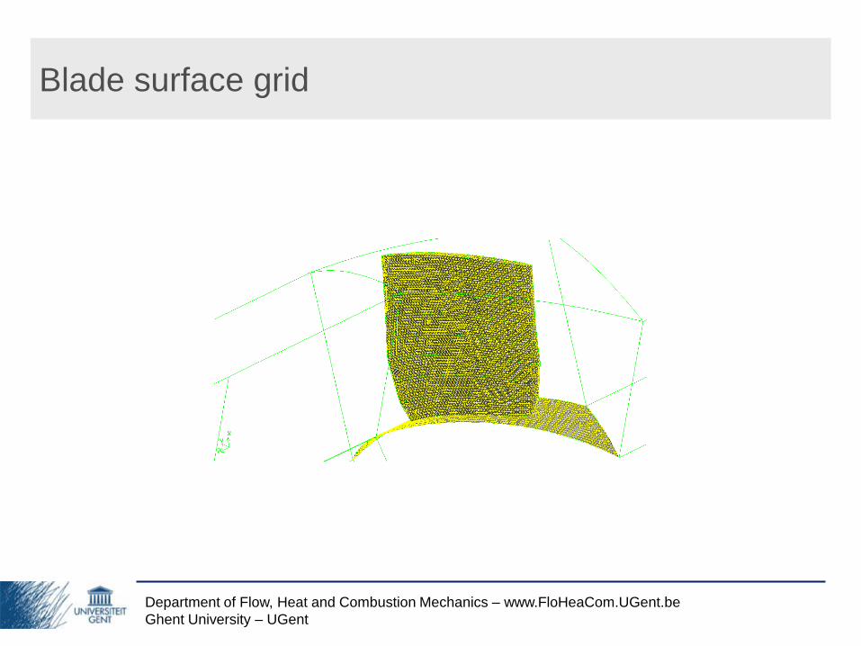
Blade surface grid

Department of Flow, Heat and Combustion Mechanics – www.FloHeaCom.UGent.be
Ghent University – UGent
Rotor flow analysis
• CFD Analysis (SRF, k-ω SST, EWT)
‣ Radius 475mm
‣ Big incidence,
but lower than expected
‣ No separation
↑ Relative Velocity Magnitude Vector (m/s)
← Static Pressure Contour (Pa)

Department of Flow, Heat and Combustion Mechanics – www.FloHeaCom.UGent.be
Ghent University – UGent
Rotor flow analysis
‣ Radius 700mm
↑ Relative Velocity Magnitude Vector (m/s)
← Static Pressure Contour (Pa)

Department of Flow, Heat and Combustion Mechanics – www.FloHeaCom.UGent.be
Ghent University – UGent
Rotor flow analysis
‣ Radius 925m
‣ Almost zero incidence
(small negative incidence)
↑ Relative Velocity Magnitude Vector (m/s)
← Static Pressure Contour (Pa)

Department of Flow, Heat and Combustion Mechanics – www.FloHeaCom.UGent.be
Ghent University – UGent
Rotor flow analysis
Suction side
Static Pressure Contour (Pa) Relative Velocity Magnitude Vector (m/s)
Department of Flow, Heat and Combustion Mechanics – www.FloHeaCom.UGent.be
Ghent University – UGent
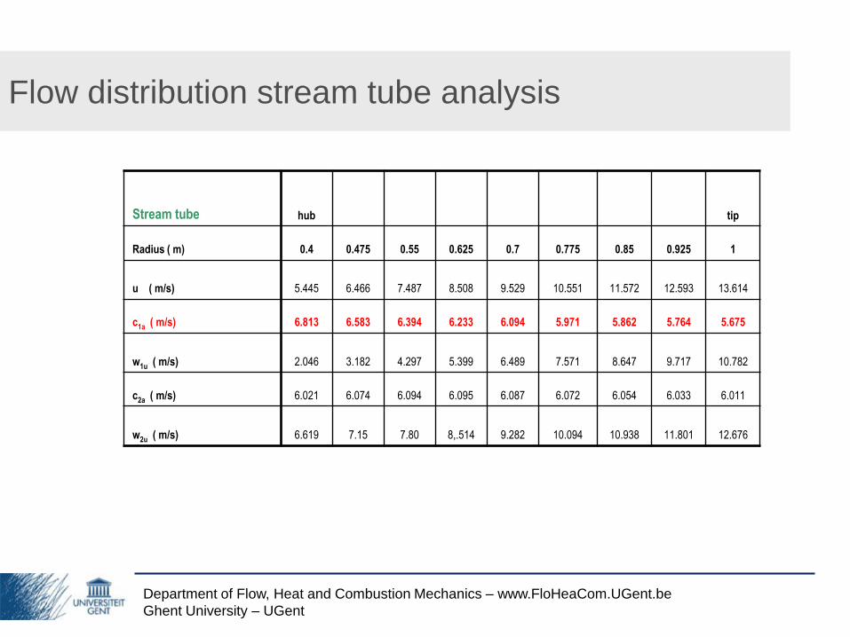
Flow distribution stream tube analysis
Stream tube hub tip
Radius ( m) 0.4 0.475 0.55 0.625 0.7 0.775 0.85 0.925 1
u ( m/s) 5.445 6.466 7.487 8.508 9.529 10.551 11.572 12.593 13.614
c1a ( m/s) 6.813 6.583 6.394 6.233 6.094 5.971 5.862 5.764 5.675
w1u ( m/s) 2.046 3.182 4.297 5.399 6.489 7.571 8.647 9.717 10.782
c2a ( m/s) 6.021 6.074 6.094 6.095 6.087 6.072 6.054 6.033 6.011
w2u ( m/s) 6.619 7.15 7.80 8,.514 9.282 10.094 10.938 11.801 12.676

Department of Flow, Heat and Combustion Mechanics – www.FloHeaCom.UGent.be
Ghent University – UGent
Flow distribution CFD analysis
CFD hub tip
Radius ( m) 0.4 0.475 0.55 0.625 0.7 0.775 0.85 0.925 1
c1a ( m/s) 4.981 6.011 5.944 5.961 6.022 6.098 6.165 6.200 5.106
w1u ( m/s) 2.305 3.249 4.384 5.472 6.563 7.626 8.692 9.737 10.586
c2a ( m/s) 5.360 6.430 6.238 6.087 5.920 5.880 6.128 5.994 4.930
w2u ( m/s) 7.002 7.645 8.395 9.250 10.104 11.035 11.842 12.697 12.931
Department of Flow, Heat and Combustion Mechanics – www.FloHeaCom.UGent.be
Ghent University – UGent
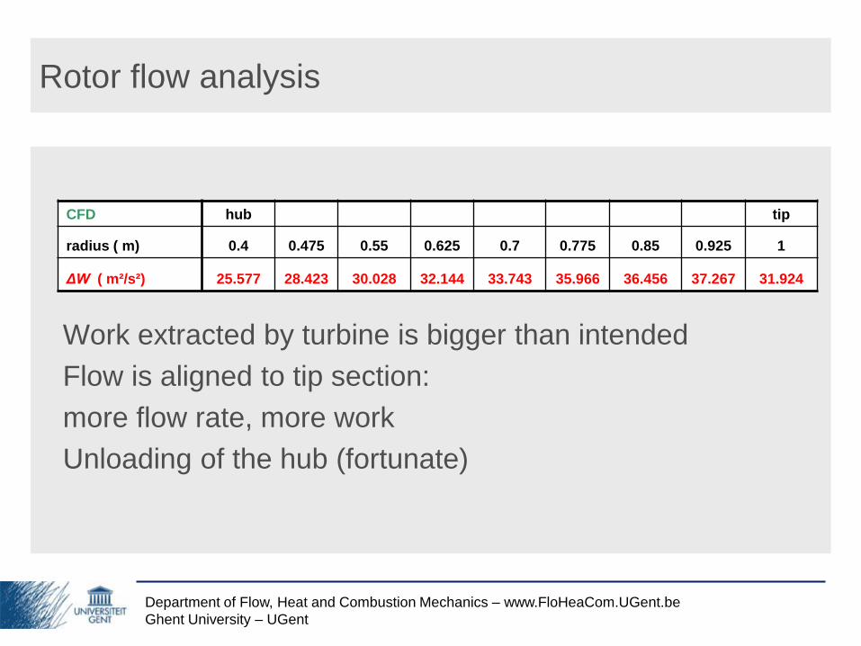
Rotor flow analysis
Work extracted by turbine is bigger than intended
Flow is aligned to tip section:
more flow rate, more work
Unloading of the hub (fortunate)
CFD hub tip
radius ( m) 0.4 0.475 0.55 0.625 0.7 0.775 0.85 0.925 1
ΔW ( m²/s²) 25.577 28.423 30.028 32.144 33.743 35.966 36.456 37.267 31.924
Department of Flow, Heat and Combustion Mechanics – www.FloHeaCom.UGent.be
Ghent University – UGent
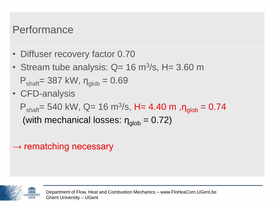
Performance
• Diffuser recovery factor 0.70
• Stream tube analysis: Q= 16 m3/s, H= 3.60 m
Pshaft= 387 kW, ηglob = 0.69
• CFD-analysis
Pshaft= 540 kW, Q= 16 m3/s, H= 4.40 m ,ηglob = 0.74
(with mechanical losses: ηglob = 0.72)
→ rematching necessary

Department of Flow, Heat and Combustion Mechanics – www.FloHeaCom.UGent.be
Ghent University – UGent
Rematching
• Work extracted by turbine is too big
→ allow bigger flow rate
• Open stator and open rotor
α = 26.5˚ → 23˚ , βtip= 63.5 ˚ → 60˚
Some loss of efficiency ηglob ≈ 0.70

Department of Flow, Heat and Combustion Mechanics – www.FloHeaCom.UGent.be
Ghent University – UGent
Overview
• Initial design
• Obtaining rotor sealingness
• Rotor flow analysis
• Diffuser flow analysis
• Off-design performance

Department of Flow, Heat and Combustion Mechanics – www.FloHeaCom.UGent.be
Ghent University – UGent
Diffuser design
• Geometry
4000mm
400mm
600mm
370mm
Mixing Plane
Inlet
Blade
Cone
Diffuser
Velocity Inlet
Pressure Outlet

Department of Flow, Heat and Combustion Mechanics – www.FloHeaCom.UGent.be
Ghent University – UGent
Diffuser analysis
• CFD Analysis (Mixing plane, k-ω SST)
‣ Static Pressure Contour(Pa)

Department of Flow, Heat and Combustion Mechanics – www.FloHeaCom.UGent.be
Ghent University – UGent
Diffuser design
• CFD Analysis (Mixing plane, k-ω SST)
‣ Radial Velocity Magnitude Contour (m/s)

Department of Flow, Heat and Combustion Mechanics – www.FloHeaCom.UGent.be
Ghent University – UGent
Diffuser design
• CFD Analysis (Mixing plane, k-ω SST)
‣ Axial Velocity Magnitude Contour (m/s)
Department of Flow, Heat and Combustion Mechanics – www.FloHeaCom.UGent.be
Ghent University – UGent
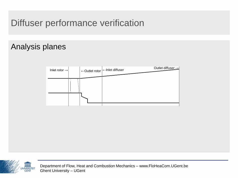
Diffuser performance verification
Analysis planes
←Outlet rotorInlet rotor →Outlet diffuser →
←Inlet diffuser

Department of Flow, Heat and Combustion Mechanics – www.FloHeaCom.UGent.be
Ghent University – UGent
Diffuser performance: pressure recovery factor
Diffuser maps:
0,700pC
2 2 2 22
44.364
1 12 0.8
2 2tip hub
L LLR
R D D
2 24 4
2 22 2
1.372.235
0.9165
A RAR
A R
4 2
22
1
2
p
p pC
v
2
4
2
11468.77
1608.21
6.112
p Pa
p Pa
v m s
0.700pC
0.700pC
CFD analysis:

Department of Flow, Heat and Combustion Mechanics – www.FloHeaCom.UGent.be
Ghent University – UGent
Diffuser performance: α = 26.5˚ → 20˚: post-swirl
Inlet diffuser
Outlet diffuser
Inlet diffuser
Outlet diffuser
Outlet diffuserInlet diffuser
= mixing plane
Axial Velocity (m/s) →
Tangential Velocity (m/s) ↓
Velocity variation

Department of Flow, Heat and Combustion Mechanics – www.FloHeaCom.UGent.be
Ghent University – UGent
Overview
• Initial design
• Obtaining rotor sealingness
• Rotor flow analysis
• Diffuser flow analysis
• Off-design performance

Department of Flow, Heat and Combustion Mechanics – www.FloHeaCom.UGent.be
Ghent University – UGent
Off-design performance:
α = 26.5˚ → 20˚ ; β = 63.5˚ → 78˚; Q=8 m3/s (H=3.20 m)
• Rotor
‣ Velocity Vector Fields:
No separated flow!
↑ Relative Velocity Magnitude Vector (m/s)
at radius 475mm
← Relative Velocity Magnitude Vector (m/s)
at radius 925mm

Department of Flow, Heat and Combustion Mechanics – www.FloHeaCom.UGent.be
Ghent University – UGent
• Diffuser
‣ Static Pressure Contour (Pa)
Off-design performance: ηglob = 0.60

Department of Flow, Heat and Combustion Mechanics – www.FloHeaCom.UGent.be
Ghent University – UGent
Conclusion
• Design of an axial hydro turbine with a movable rotor and
blade shape such that the rotor can be completely closed
was successful
• Rated conditions: Q= 16 m3/s, H= 3.60 m
Pshaft= 390 kW, ηglob = 0.70
• Half flow rate: ηglob = 0.60