1 electrical technology eet 103/4 define and explain sine wave, frequency, amplitude, phase angle,...
TRANSCRIPT

1
ELECTRICAL TECHNOLOGY EET 103/4
Define and explain sine wave, frequency, amplitude, phase angle, complex number
Define, analyze and calculate impedance, inductance, phase shifting
Explain and calculate active power, reactive power, power factor
Define, explain, and analyze Ohm’s law, KCL, KVL, Source Transformation, Thevenin theorem.

2
(CHAPTER 13)
SINUSOIDAL ALTERNATINGSINUSOIDAL ALTERNATINGWAVEFORMSWAVEFORMS

3
13.1 Introduction
Alternating waveformsThe term alternating indicates only that the
waveform alternates between two prescribed levels in a set time sequence.

4
13.2 Sinusoidal ac Voltage Characteristics and Definitions
GenerationAn ac generator (or alternator) powered by
water power, gas, or nuclear fusion is the primary component in the energy-conversion process.
The energy source turns a rotor (constructed of alternating magnetic poles) inside a set of windings housed in the stator (the stationary part of the dynamo) and will induce voltage across the windings of the stator.
dt
dNe

5
13.2 Sinusoidal ac Voltage Characteristics and Definitions
Generation Wind power and solar power energy are receiving
increased interest from various districts of the world.The turning propellers of the wind-power station are
connected directly to the shaft of an ac generator.
Light energy in the form of photons can be absorbed by solar cells. Solar cells produce dc, which can be electronically converted to ac with an inverter.
A function generator, as used in the lab, can generate and control alternating waveforms.

6
13.2 Sinusoidal ac Voltage Characteristics and Definitions
Definitions Waveform: The path traced by a quantity, such
as voltage, plotted as a function of some variable such as time, position, degree, radius, temperature and so on.
Instantaneous value: The magnitude of a waveform at any instant of time; denoted by the lowercase letters (e1, e2).
Peak amplitude: The maximum value of the waveform as measured from its average (or mean) value, denoted by the uppercase letters Em (source of voltage) and Vm (voltage drop across a load).
7
13.2 Sinusoidal ac Voltage Characteristics and Definitions
DefinitionsPeak value: The maximum instantaneous value
of a function as measured from zero-volt level. Peak-to-peak value: Denoted by Ep-p or Vp-p, the
full voltage between positive and negative peaks of the waveform, that is, the sum of the magnitude of the positive and negative peaks.
Periodic waveform: A waveform that continually repeats itself after the same time interval.

8
13.2 Sinusoidal ac Voltage Characteristics and Definitions

9
13.2 Sinusoidal ac Voltage Characteristics and Definitions
DefinitionsPeriod (T): The time interval between
successive repetitions of a periodic waveform (the period T1 = T2 = T3), as long as successive similar points of the periodic waveform are used in determining T
Cycle: The portion of a waveform contained in one period of time
Frequency: (Hertz) the number of cycles that occur in 1 s
Hz hertz,1
Tf

10
Heinrich Rudolph Hertz.

11
13.2 Sinusoidal ac Voltage Characteristics and Definitions

12
13.2 Sinusoidal ac Voltage Characteristics and Definitions

13
13.2 Sinusoidal ac Voltage Characteristics and Definitions
Example 13.1 Determine:(a) peak value(b) instantaneous value at 0.3 s and 0.6 s(c) peak-to-peak value(d) period(e) how many cycles are shown(f) frequency

14
13.2 Sinusoidal ac Voltage Characteristics and Definitions
Example 13.1 – solution
(a) 8 V; (b) -8 V at 3 s and 0 V at 0.6 s; (c) 16 V;(d) 0.4 s; (e) 3.5 cycles; (f) 2.5 Hz
15
13.2 Sinusoidal ac Voltage Characteristics and Definitions
Example 13.2Find the period of periodic waveform with frequency of;
(a) 60 Hz (b) 1000 Hz
Solution
(a) ms 67.1660
11
fT
(b) ms 11000
11
fT

16
13.2 Sinusoidal ac Voltage Characteristics and Definitions
Example 13.3
Determine the frequency of the following waveform

17
13.2 Sinusoidal ac Voltage Characteristics and Definitions
Example 13.3 – solution
ms 20T
From the waveform;
Hz 501020
113
Tf

18
13.2 Sinusoidal ac Voltage Characteristics and Definitions
Defined Polarities and Direction
The polarity and current direction will be for an instant in time in the positive portion of the sinusoidal waveform.
In the figure, a lowercase letter is employed for polarity and current direction to indicate that the quantity is time dependent; that is, its magnitude will change with time.

19
13.2 Sinusoidal ac Voltage Characteristics and Definitions
Defined Polarities and Direction

20
13.4 The Sinusoidal Waveform
The sinusoidal waveform is the only alternating waveform whose shape is unaffected by the response characteristics of R, L, and C elements.
The voltage across (or current through) a resistor, coil, or capacitor is sinusoidal in nature.
The unit of measurement for the horizontal axis is the degree. A second unit of measurement frequently used is the radian (rad).
57.357.296 rad 1

21
13.4 The Sinusoidal Waveform If we define x as the number of intervals of r (the
radius) around the circumference of a circle, then
and we find
Therefore, there are 2 rad around a 360° circle, as shown in the figure.
xrrC 2 2x
22
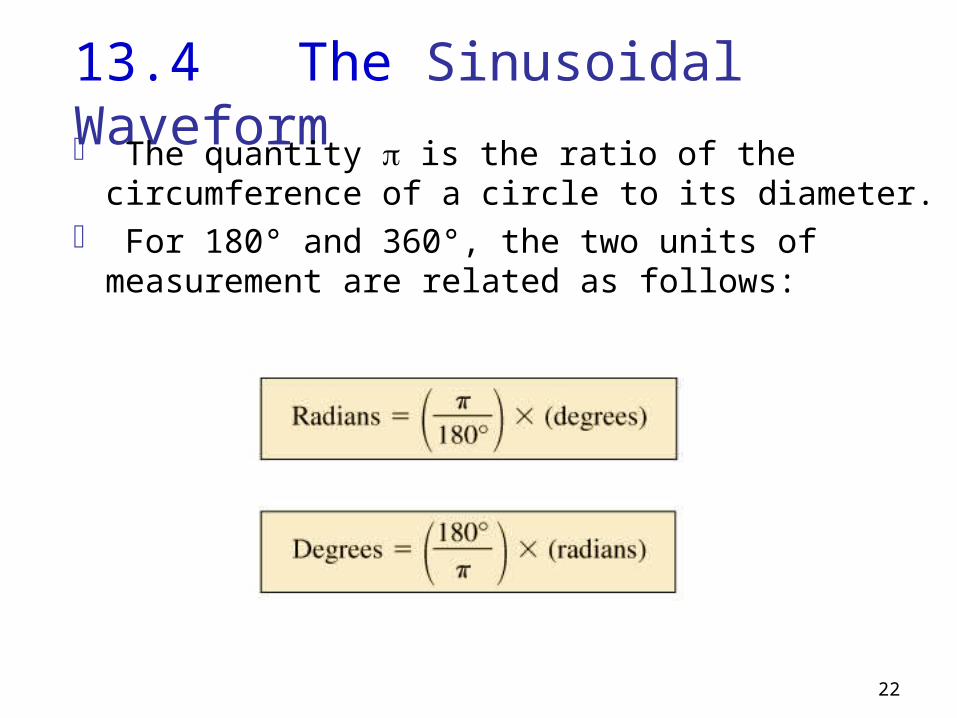
13.4 The Sinusoidal Waveform The quantity is the ratio of the circumference of
a circle to its diameter. For 180° and 360°, the two units of measurement
are related as follows:

23
13.4 The Sinusoidal Waveform The sinusoidal wave form can be derived
from the length of the vertical projection of a radius vector rotating in a uniform circular motion about a fixed point.
The velocity with which the radius vector rotates about the center, called the angular velocity, can be determined from the following equation:
24
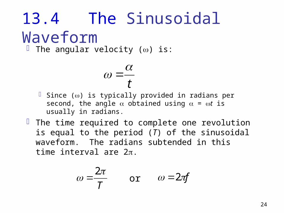
13.4 The Sinusoidal Waveform The angular velocity () is:
Since () is typically provided in radians per second, the angle obtained using = t is usually in radians.
The time required to complete one revolution is equal to the period (T) of the sinusoidal waveform. The radians subtended in this time interval are 2.
t
T
2 or f 2
25
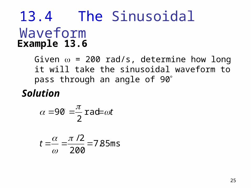
13.4 The Sinusoidal WaveformExample 13.6
Given = 200 rad/s, determine how long it will take the sinusoidal waveform to pass through an angle of 90
Solution
t rad 2
90
ms 85.7200
2/
t

26
13.4 The Sinusoidal WaveformExample 13.7
Find the angle through which a sinusoidal waveform of 60 Hz will pass in a period of 5 ms.
Solution
rad 885.11056022 3 ftt
108180
885.1

27
13.5 General Format for the Sinusoidal Voltage or Current
• The basic mathematical format for the sinusoidal waveform is:
where:Am is the peak value of
the waveform
is the unit of measure for the horizontal axis

28
13.5 General Format for the Sinusoidal Voltage or Current
The equation = t states that the angle through which the rotating vector will pass is determined by the angular velocity of the rotating vector and the length of time the vector rotates.
For a particular angular velocity (fixed ), the longer the radius vector is permitted to rotate (that is, the greater the value of t ), the greater will be the number of degrees or radians through which the vector will pass.
The general format of a sine wave can also be as:
29
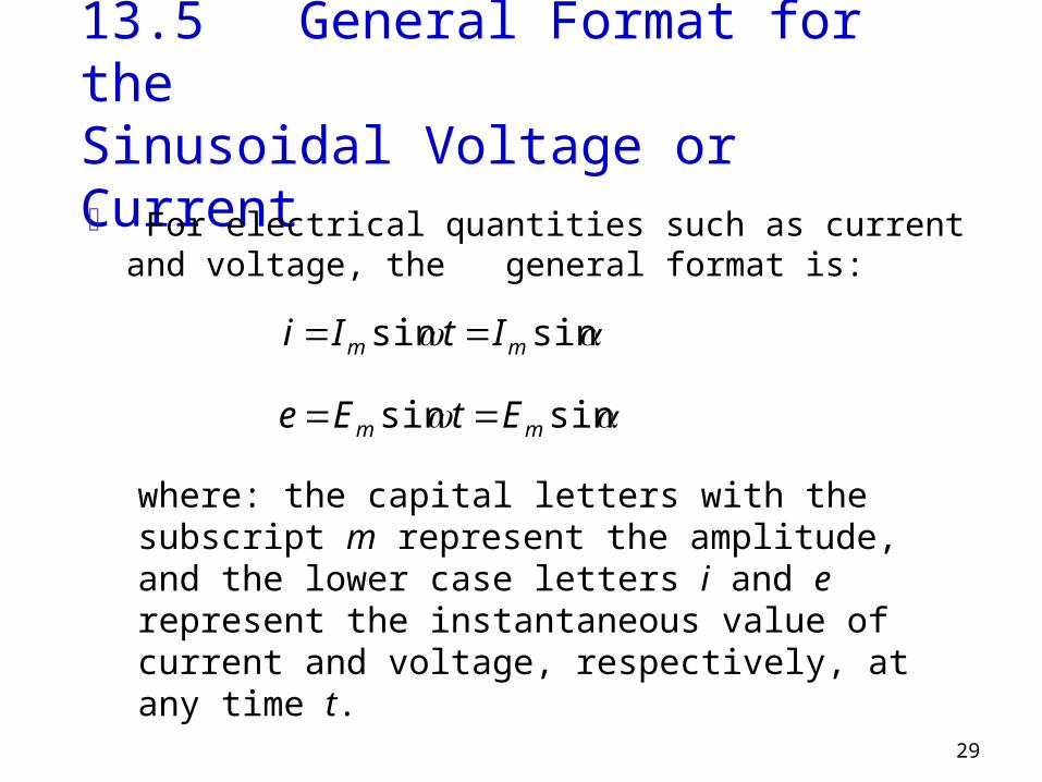
13.5 General Format for the Sinusoidal Voltage or Current
For electrical quantities such as current and voltage, the general format is:
sinsin mm ItIi
sinsin mm EtEe
where: the capital letters with the subscript m represent the amplitude, and the lower case letters i and e represent the instantaneous value of current and voltage, respectively, at any time t.
30
13.5 General Format for the Sinusoidal Voltage or Current
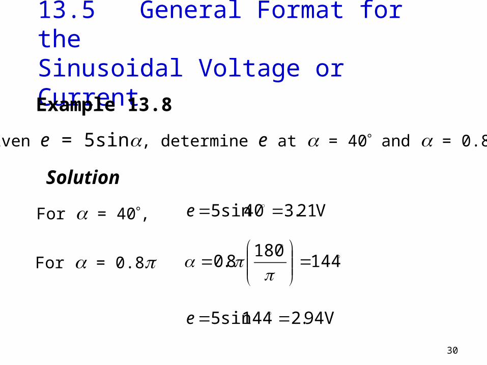
Example 13.8
Given e = 5sin, determine e at = 40 and = 0.8.
Solution
For = 40, V 21.340sin5 e
For = 0.8
144180
8.0
V 94.2144sin5 e
31
13.5 General Format for the Sinusoidal Voltage or Current
Example 13.9
(a) Determine the angle at which the magnitude of the sinusoidal function v = 10 sin 377t is 4 V.
(b) Determine the time at which the magnitude is attained.
32
13.5 General Format for the Sinusoidal Voltage or Current
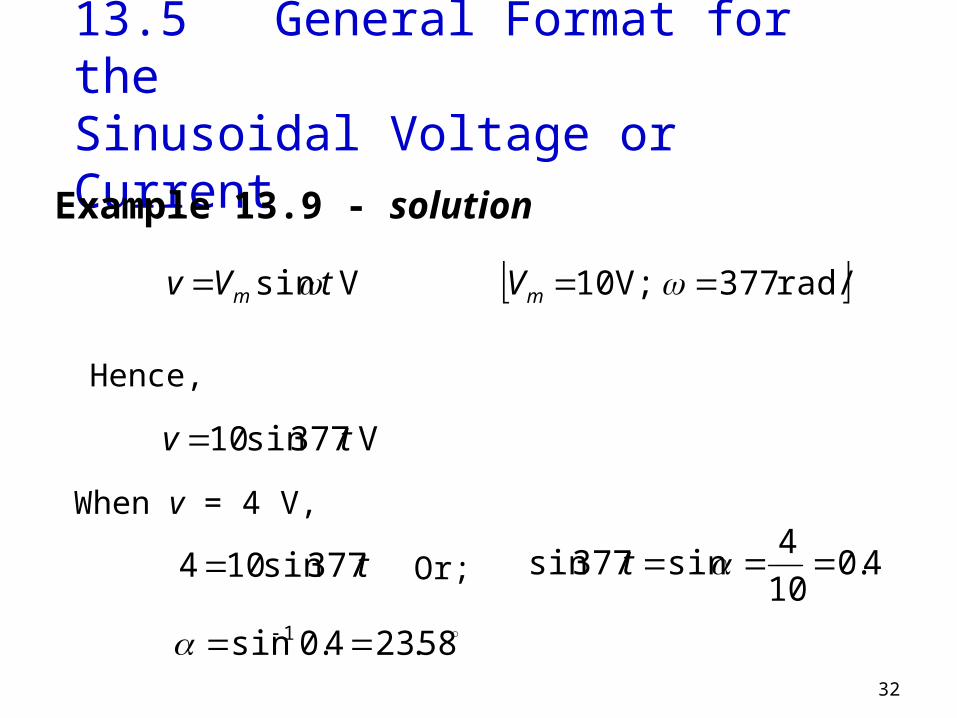
Example 13.9 - solution
V sin tVv m rad/s 377 V; 10 mV
Hence,
V 377sin10 tv
When v = 4 V,
t377sin104 Or; 4.010
4sin377sin t
58.234.0sin 1
33
13.5 General Format for the Sinusoidal Voltage or Current
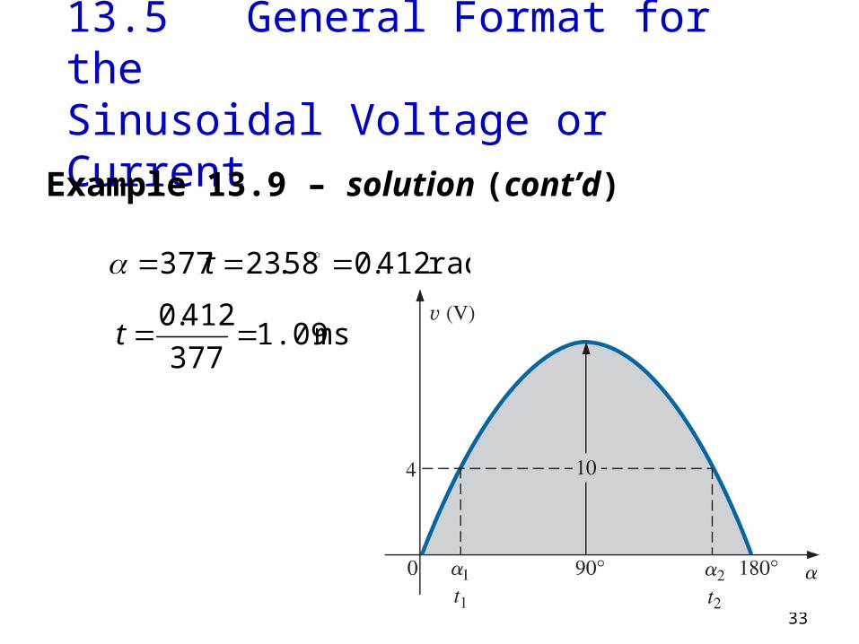
Example 13.9 – solution (cont’d)
rad 412.058.23377 t
ms 1.09377
412.0t

34
13.6 Phase Relationship
tAa m sin
The unshifted sinusoidal waveform is represented by the expression:
t

35
13.6 Phase Relationship
where is the angle (in degrees or radians) that the waveform has been shifted.
Sinusoidal waveform which is shifted to the right or left of 0° is represented by the expression:
tAa m sin
36
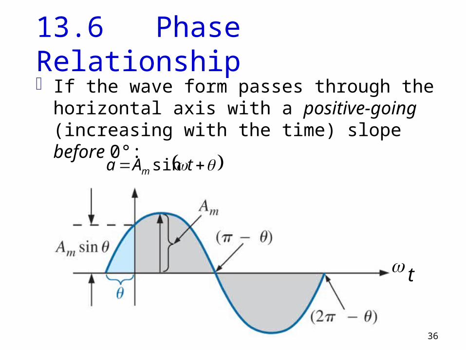
13.6 Phase RelationshipIf the wave form passes through the horizontal
axis with a positive-going (increasing with the time) slope before 0°:
tAa m sin
t
37
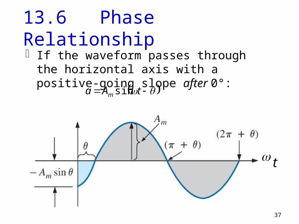
13.6 Phase RelationshipIf the waveform passes through the horizontal
axis with a positive-going slope after 0°:
tAa m sin
t

38
13.6 Phase RelationshipThe terms lead and lag are used to indicate
the relationship between two sinusoidal waveforms of the same frequency plotted on the same set of axes.
• The cosine curve is said to lead the sine curve by 90.
• The sine curve is said to lag the cosine curve by 90.
• 90 is referred to as the phase angle between the two waveforms.

39
13.6 Phase Relationship
t

40
13.6 Phase RelationshipIf a sinusoidal expression should appear as
tEe m sin
the negative sign is associated with the sine portion of the expression, not the peak value Em , i.e.
tEetEe mm sinsin
And, since; 180sinsin tt
180sinsin tEtE mm

41
13.6 Phase RelationshipIf a sinusoidal expression should appear as
tEe m sin
the negative sign is associated with the sine portion of the expression, not the peak value Em , i.e.
tEetEe mm sinsin
And, since; 180sinsin tt
180sinsin tEtE mm

42
13.6 Phase Relationship
Determine the phase relationship between the following waveforms;
70sin5
30sin10 (a)
ti
tv
Example 13.2
20sin10
60sin15 (b)
tv
ti
10sin3
10cos2 (c)
tv
ti
10sin2
30sin (d)
tv
ti

43
13.6 Phase Relationship
70sin5
30sin10 (a)
ti
tv
Example 13.2 – solution
i leads v by 40Or
v lags i by 40

44
13.6 Phase RelationshipExample 13.2 – solution (cont’d)
i leads v by 80Or
v lags i by 80
20sin10
60sin15 (b)
tv
ti

45
13.6 Phase RelationshipExample 13.2 – solution (cont’d)
i leads v by 110Or
v lags i by 110
10sin3
10cos2 (c)
tv
ti

46
13.6 Phase RelationshipExample 13.2 – solution (cont’d)
v leads i by 160Or
i lags v by 160
10sin2
30sin (d)
tv
ti
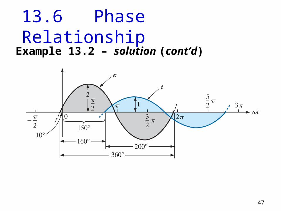
i leads v by 200Or
v lags i by 200
OR
47
13.6 Phase RelationshipExample 13.2 – solution (cont’d)
48
13.7 Average Value
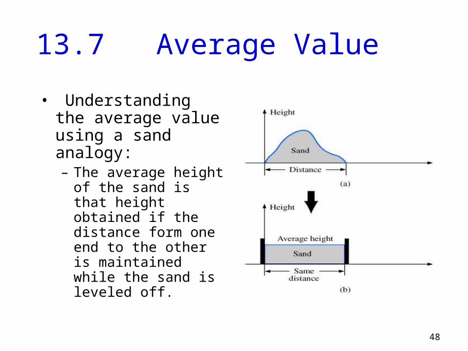
• Understanding the average value using a sand analogy:– The average height
of the sand is that height obtained if the distance form one end to the other is maintained while the sand is leveled off.

49
13.7 Average Value
The algebraic sum of the areas must be determined, since some area contributions will be from below the horizontal axis.
Area above the axis is assigned a positive sign and area below the axis is assigned a negative sign.
The average value of any current or voltage is the value indicated on a dc meter – over a complete cycle the average value is the equivalent dc value.
50
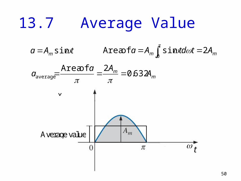
13.7 Average Value
tAa m sin
t
Average value
mm AtdtAa 2sin of Area0
mm AAa
a 632.02 of Area
average

51
13.7 Effective (rms) Value
T
dttiI
T
0
2
(rms) tIti m sin
tItIti mm cos212
1sin 2222
T
dttII
T
m
0
2
(rms)
cos2121
2(rms)
mII

52
13.7 Effective (rms) ValueExample 13.21
The 120 V dc source delivers 3.6 W to the load. Find Em and Im of the ac source, if the same power is to be delivered to the load.

53
13.7 Effective (rms) ValueExample 13.21 – solution
W6.3dcdc PIE mA 30120
6.3
dcdc
E
PI
2dcrms
mEEE
V 7.169120414.12 dc EEm
and2
dcrmsmIII
mA 43.4230414.12 dc IIm

54
13.7 Effective (rms) ValueExample 13.21 – solution
2dcrms
mIII
2dcrms
mEEE
rms2EEm
V 7.169
120414.1