1 ee462l, fall 2011 motor drives and other applications
TRANSCRIPT

1
EE462L, Fall 2011Motor Drives and Other Applications

2(Source: EPRI Adjustable Speed Drives Application Guide)
Three-Phase Induction Motors
• Reliable
• Rugged
• Long lived
• Low maintenance
• Efficient

3
At no load, the motor spins at grid frequency, divided by the number of pole pairs. Usually this is 3600 / 2 = 1800RPM
Slip frequency (about 5% of no load speed), so induction motors are almost constant speed devices

4
High slip corresponds to low efficiency
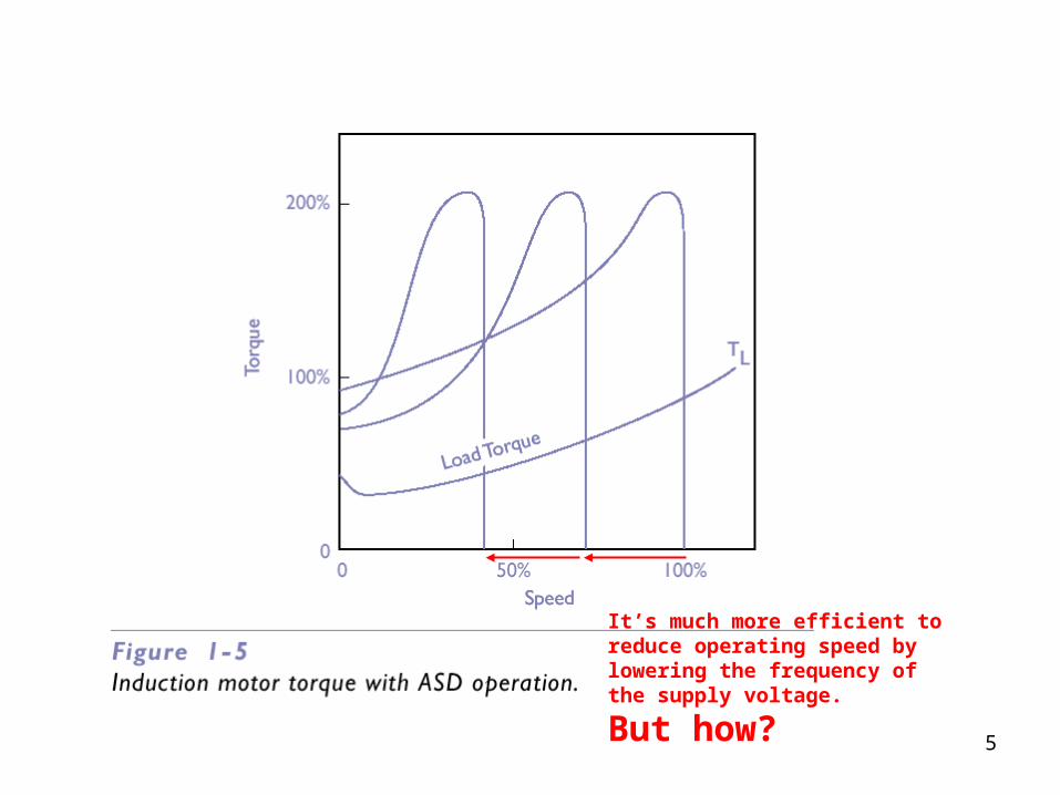
5
It’s much more efficient to reduce operating speed by lowering the frequency of the supply voltage.
But how?

6
Adjustable-Speed Motor Drives (ASDs)
(Source: EPRI Adjustable Speed Drives Application Guide)

7
Some Prices for Small 3-Phase, 460V Induction Motors and ASDs
$50 - $75 per kW $150 - $200 per kW
Power Motor ASD
10kW $750 $2,000
100kW $5,000 $15,000
For Comparison, Conventional Generation: $500 - $1,000 per kW
Solar: $4,000 - $6,000 per kW (but the fuel is free forever!)

Chapter 14 InductionMotor Drives
14-8
Pump Application: Adjustable Flow rate
• Fixed versus adjustable speed drive
Bad news – inefficient!
Equivalent to reducing the output voltage of a DBR with a series resistor
Payback in energy savings is about 1 year
Source: Ned Mohan’s power electronics book

Chapter 14 InductionMotor Drives
14-9
Per-Phase Representation(assuming sinusoidal steady state)
Because of the shunt inductance term, we must reduce the applied voltage magnitude in proportion to applied frequency to avoid serious saturation of the iron near the air gap
This is what is called “Constant Volts per Hertz Operation,” which is the standard operating mode for ASDs
Source: Ned Mohan’s power electronics book

Chapter 14 InductionMotor Drives
14-10
Torque-Speed Characteristics
• The linear part of the characteristic is utilized in adjustable speed drives
Source: Ned Mohan’s power electronics book

Chapter 14 InductionMotor Drives
14-11
Acceleration Torque at Startup
• Intersection represents the equilibrium point
Source: Ned Mohan’s power electronics book
Chapter 14 InductionMotor Drives
14-12
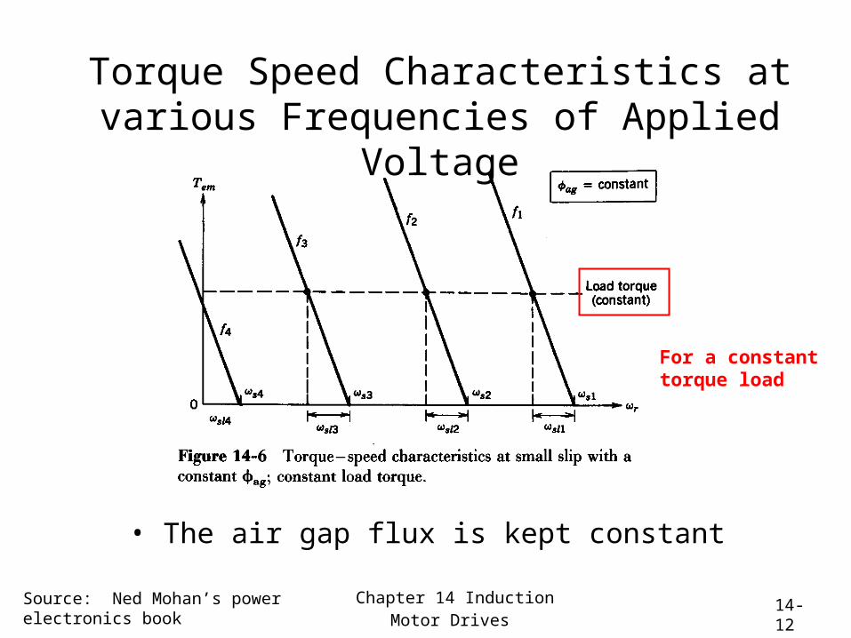
Torque Speed Characteristics at various Frequencies of Applied Voltage
• The air gap flux is kept constant
For a constant torque load
Source: Ned Mohan’s power electronics book

Chapter 14 InductionMotor Drives
14-13
Adjusting Speed of a Centrifugal Load
• The load torque is proportional to speed squared
Source: Ned Mohan’s power electronics book

Chapter 14 InductionMotor Drives
14-14
Frequency at Startup
• The torque is limited to limit current draw
Zero speed
An important property of ASDs is the ability to “soft start” a motor by reducing the applied frequency to a few Hz
Source: Ned Mohan’s power electronics book

Chapter 14 InductionMotor Drives
14-15
PWM-VSI System
• Diode rectifier for unidirectional power flow
A three-phase DBR
A three-phase inverter
Source: Ned Mohan’s power electronics book

Chapter 8 Switch-Mode DC-Sinusoidal AC Inverters
8-16
Three-Phase Inverter
• Three inverter legs; capacitor mid-point is fictitious
(called a six-pack)
Source: Ned Mohan’s power electronics book

Chapter 8 Switch-Mode DC-Sinusoidal AC Inverters
8-17
Three-Phase PWM
Waveforms
Source: Ned Mohan’s power electronics book

Chapter 8 Switch-Mode DC-Sinusoidal AC Inverters
8-18
Three-Phase Inverter Harmonics
Source: Ned Mohan’s power electronics book

Chapter 8 Switch-Mode DC-Sinusoidal AC Inverters
8-19
Three-Phase Inverter Output
• Linear and over-modulation ranges
Source: Ned Mohan’s power electronics book

Chapter 16 Residential andIndustrial Applications
16-20
Improving Energy Efficiency of Heat Pumps
• Used in one out of three new homes in the U.S.
How does inserting an ASD save energy in single-phase applications?
Some losses
But a three-phase motor is 95% efficient, compared to 80% efficiency for a single-phase motor
Source: Ned Mohan’s power electronics book

Chapter 16 Residential andIndustrial Applications
16-21
Loss Associated with ON/OFF Cycling
• The system efficiency is improved by ~30 percent
The big efficiency gain is here
• with conventional air conditioners, the first few minutes after start-up are very inefficient as the mechanical system reaches steady-state
• with ASDs, the air conditioner speed is lowered with demand, so that there are fewer start-ups each day
Source: Ned Mohan’s power electronics book

Chapter 16 Residential andIndustrial Applications
16-22
Electronic Ballast for Fluorescent Lamps
• Lamps operated at ~40 kHz save energy
Source: Ned Mohan’s power electronics book

Chapter 16 Residential andIndustrial Applications
16-23
Induction Cooking
• Pan is heated directly by circulating currents – increases efficiency
Source: Ned Mohan’s power electronics book

Chapter 16 Residential andIndustrial Applications
16-24
Industrial Induction Heating
Source: Ned Mohan’s power electronics book

Chapter 17 ElectricUtility Applications
17-25
HVDC Transmission
• There are many such systems all over the world
Source: Ned Mohan’s power electronics book

Chapter 17 ElectricUtility Applications
17-26
HVDC Poles
• Each pole consists of 12-pulse converters
Source: Ned Mohan’s power electronics book
Chapter 17 ElectricUtility Applications
17-27
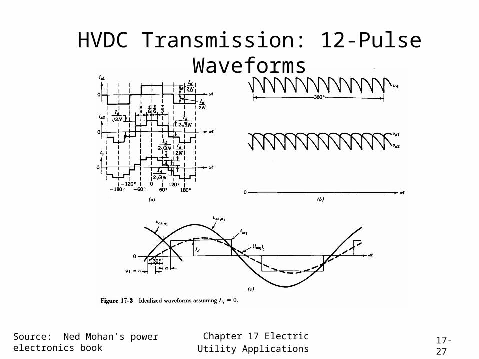
HVDC Transmission: 12-Pulse Waveforms
Source: Ned Mohan’s power electronics book

Chapter 18 Utility Interface 18-28
Reducing the Input Current Distortion
Like DBR current (high distortion)
Source: Ned Mohan’s power electronics book

Chapter 18 Utility Interface 18-29
Power-Factor-Correction (PFC) Circuit
The boost converter is operated to make the DBR current look sinusoidal on the AC side
To be sold in Europe, this is a necessary feature in high-current single-phase power electronic loads
It also permits more power to be drawn from conventional wall outlets because the harmonic currents are minimal
Source: Ned Mohan’s power electronics book

Chapter 18 Utility Interface 18-30
Power-Factor-Correction (PFC) Circuit
• Operation during each half-cycle
The boost converter is instructed to
“close” when the current is below the sinewave envelope, and
“open” with the current is above the sinewave envelopeclose
open
Source: Ned Mohan’s power electronics book

Chapter 18 Utility Interface 18-31
Power Electronics Has Made Wind Farms Possible
The choices used to be
• Use an efficient induction generator, which has very poor power factor, or
• Use a synchronous generator, but constantly fight to synchronize the turbine speed with the grid.
Now,
• Either use a DC bus and inverter to decouple the generator and grid AC busses, or
• Use a doubly-fed induction motor, operate the wind turbine at the max power speed, and use power electronics to “trick” the wind generator into producing grid-frequency output. This is what you see in West Texas.