1 duke ry power. vice president / 7800 rochester highway
TRANSCRIPT
1 Duke RON A. JONES
rY Power. Vice PresidentA Duke Energy Company Oconee Nuclear Site
Duke PowerONOI VP / 7800 Rochester HighwaySeneca, SC 29672
864 885 3158
864 885 3564 fax
August 20, 2004
U. S. Nuclear Regulatory CommissionWashington, D. C. 20555
Attention: Document Control Desk
Subject: Oconee Nuclear StationDocket Numbers 50-269, 270, and 287License Amendment Request to revise RBS flowTechnical Specifications based on recent ReactorBuilding Spray System ModificationsTechnical Specification Change (TSC) Number2004-01
Pursuant to Title 10, Code of Federal Regulations (CFR),Part 50, Section 90 (10 CFR 50.90), Duke Energy Corporation(Duke) proposes to amend Appendix A, TechnicalSpecifications, for Facility Operating Licenses DPR-38, DPR-47 and DPR-55 for Oconee Nuclear Station (ONS), Units 1, 2,and 3. The proposed amendment revises TechnicalSpecification (TS) 3.3.8, "Post Accident MonitoringInstrumentation," to eliminate TS requirements associatedwith the Reactor Building Spray (RBS) flow instrumentscommensurate with the importance of their revised postaccident function.
The Reactor Building Spray (RBS) System has been recentlymodified on all three Oconee Units to improve post-accidentRBS operation. The modification eliminates the need tomanually throttle RBS flow rate within 15 minutes ofaccident mitigation during the injection phase of post-accident operation, and the need to manually throttle RBSflow rate prior to transferring suction to the ReactorBuilding Emergency Sump (RBES). With this change, the RBSflow instrument is only needed to monitor operation of theRBS System. Per Regulatory Guide (RG) 1.97, Revision 3,Table 3, this variable is Category 2, Type D. Since the RBSflow is no longer a Type A or Category 1 variable, Dukeproposes to eliminate the TS requirements for the RBS flowinstruments.
www.dukepower.comr

U. S. Nuclear Regulatory CommissionAugust 20, 2004Page 2
The revised TS pages are included in Attachment 1.Attachment 2 contains the markup of the current TS pages.The Technical Justification for the amendment request isincluded in Attachment 3. Attachments 4 and 5 contain theNo Significant Hazards Consideration Evaluation and theEnvironmental Impact Analysis, respectively.
The proposed changes to the Technical Specifications havebeen reviewed and approved by the Plant Operations ReviewCommittee and Nuclear Safety Review Board.
Approval of this proposed LAR is requested by August 31,2005. A 90-day implementation period is requested for theTechnical Specification change.
Implementation of these changes will not result in an unduerisk to the health and safety of the public.
UFSAR changes necessary to reflect approval of thissubmittal will be made in accordance 10 CFR 50.71(e).
Pursuant to 10 CFR 50.91, a copy of this proposed amendmentis being sent to the South Carolina Department of Health andEnvironmental Control for review, and as deemed necessaryand appropriate, subsequent consultation with the NRC staff.
If there are any additional questions, please contact BoydShingleton at (864) 885-4716.
Very r y yours,
R. A nes, Vice PresidentOconee Nuclear Site

U. S. Nuclear Regulatory CommissionAugust 20, 2004Page 3
cc: Mr. L. N. Olshan, Project ManagerOffice of Nuclear Reactor RegulationU. S. Nuclear Regulatory CommissionMail Stop 0-14 H25Washington, D. C. 20555
Mr. W. D. Travers, Regional AdministratorU. S. Nuclear Regulatory Commission - Region IIAtlanta Federal Center61 Forsyth St., SW, Suite 23T85Atlanta, Georgia 30303
Mr. M. C. ShannonSenior Resident InspectorOconee Nuclear Station
Mr. Henry Porter, DirectorDivision of Radioactive Waste ManagementBureau of Land and Waste ManagementDepartment of Health & Environmental Control2600 Bull StreetColumbia, SC 29201
U. S. Nuclear Regulatory CommissionAugust 20, 2004Page 4
R. A. Jones, being duly sworn, states that he is VicePresident, Oconee Nuclear Site, Duke Energy Corporation,that he is authorized on the part of said Company to signand file with the U. S. Nuclear Regulatory Commission thisrevision to the Renewed Facility Operating License Nos. DPR-38, DPR-47, DPR-55; and that all the statements and mattersset forth herein are true and correct to the best of hisknowledge7)
R. A.Ocone'
. Vice President
Se a)scrib d~~bACkJt,
and sworn to before me this O S iday of2004
And . / - k'~otary Public
My Commission Expires:
.. I .
. _1
- /2- -oL-3. I
Z
-. .7
August 20, 2004
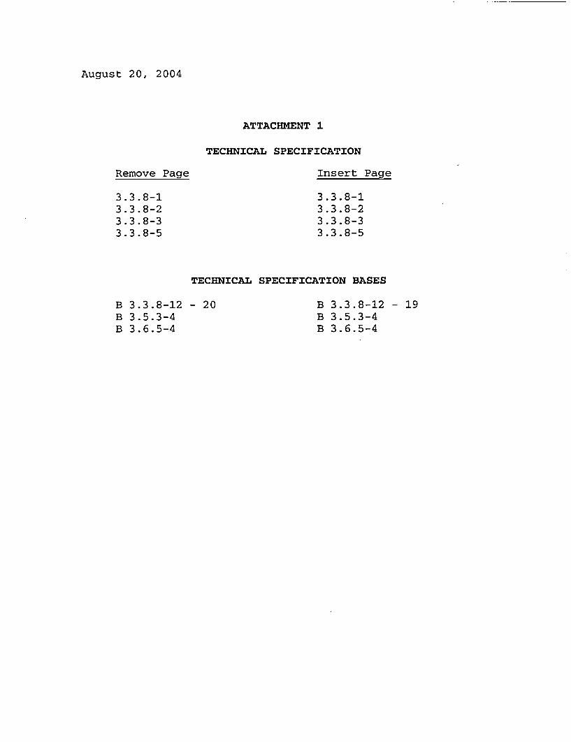
ATTACHMENT 1
TECHNICAL SPECIFICATION
Remove Page Insert Page
3.3.8-13.3.8-23.3.8-33.3.8-5
3.3.8-13.3.8-23.3.8-33.3.8-5
TECHNICAL SPECIFICATION BASES
B 3.3.8-12 - 20B 3.5.3-4B 3.6.5-4
B 3.3.8-12 - 19B 3.5.3-4B 3.6.5-4

PAM Instrumentation3.3.8
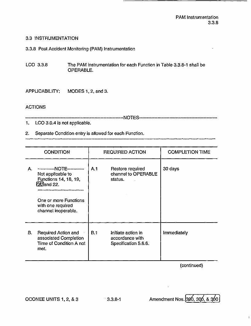
3.3 INSTRUMENTATION
3.3.8 Post Accident Monitoring (PAM) Instrumentation
LCO 3.3.8 The PAM instrumentation for each Function in Table 3.3.8-1 shall beOPERABLE.
APPLICABILITY: MODES 1, 2, and 3.
ACTIONS
----------------------------------------- NO1. LCO 3.0.4 is not applicable.
TES--
2. Separate Condition entry is allowed for each Function.
CONDITION REQUIRED ACTION COMPLETION TIME
A. -----------NOTE----------- A.1 Restore required 30 daysNot applicable to channel to OPERABLEFunctions 14, 18, 19, status.and 22.
One or more Functionswith one requiredchannel inoperable.
B. Required Action and B.1 Initiate action in Immediatelyassociated Completion accordance withTime of Condition A not Specification 5.6.6.met.
(continued)
I
OCONEE UNITS 1, 2, & 3 3.3.8-1 Amendment Nos. I
PAM Instrumentation3.3.8
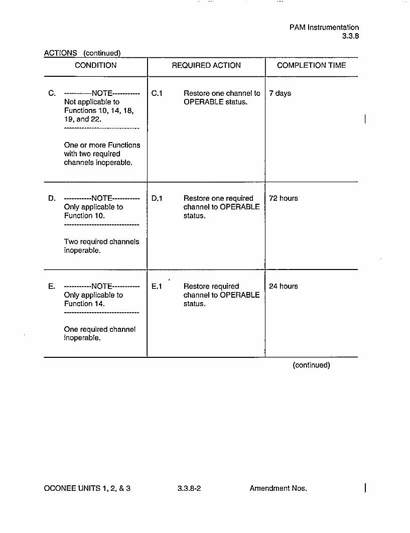
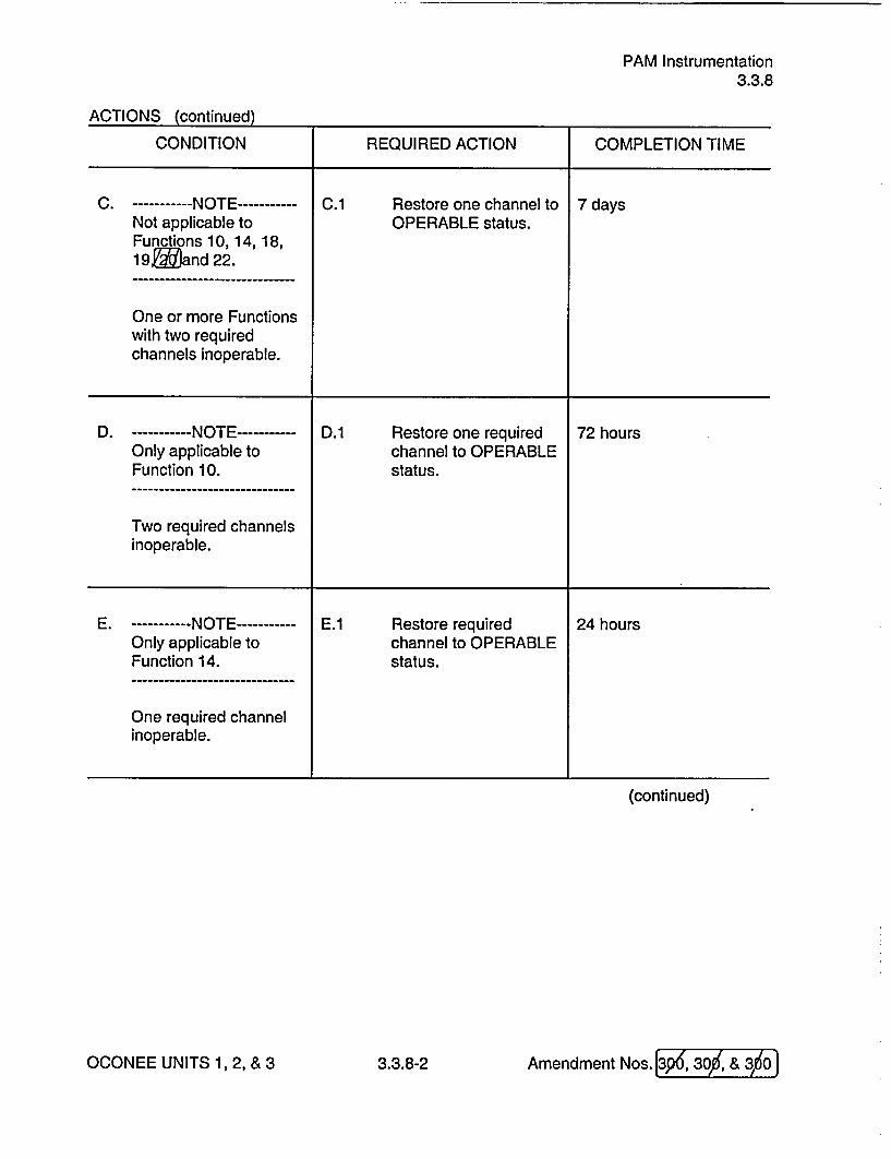
ACTIONS (continued)
CONDITION REQUIRED ACTION COMPLETION TIME
C. ------ NOTE----------- C.1 Restore one channel to 7 daysNot applicable to OPERABLE status.Functions 10, 14, 18,19, and 22.
One or more Functionswith two requiredchannels inoperable.
D. -----------NOTE----------- D.1 Restore one required 72 hoursOnly applicable to channel to OPERABLEFunction 10. status.
Two required channelsinoperable.
E. -----------NOTE----------- E.1 Restore required 24 hoursOnly applicable to channel to OPERABLEFunction 14. status.
One required channelinoperable.
(continued)
OCONEE UNITS 1,2, &3 3.3.8-2 Amendment Nos. I
PAM Instrumentation3.3.8
ACTIONS (continued)
CONDITION REQUIRED ACTION COMPLETION TIME
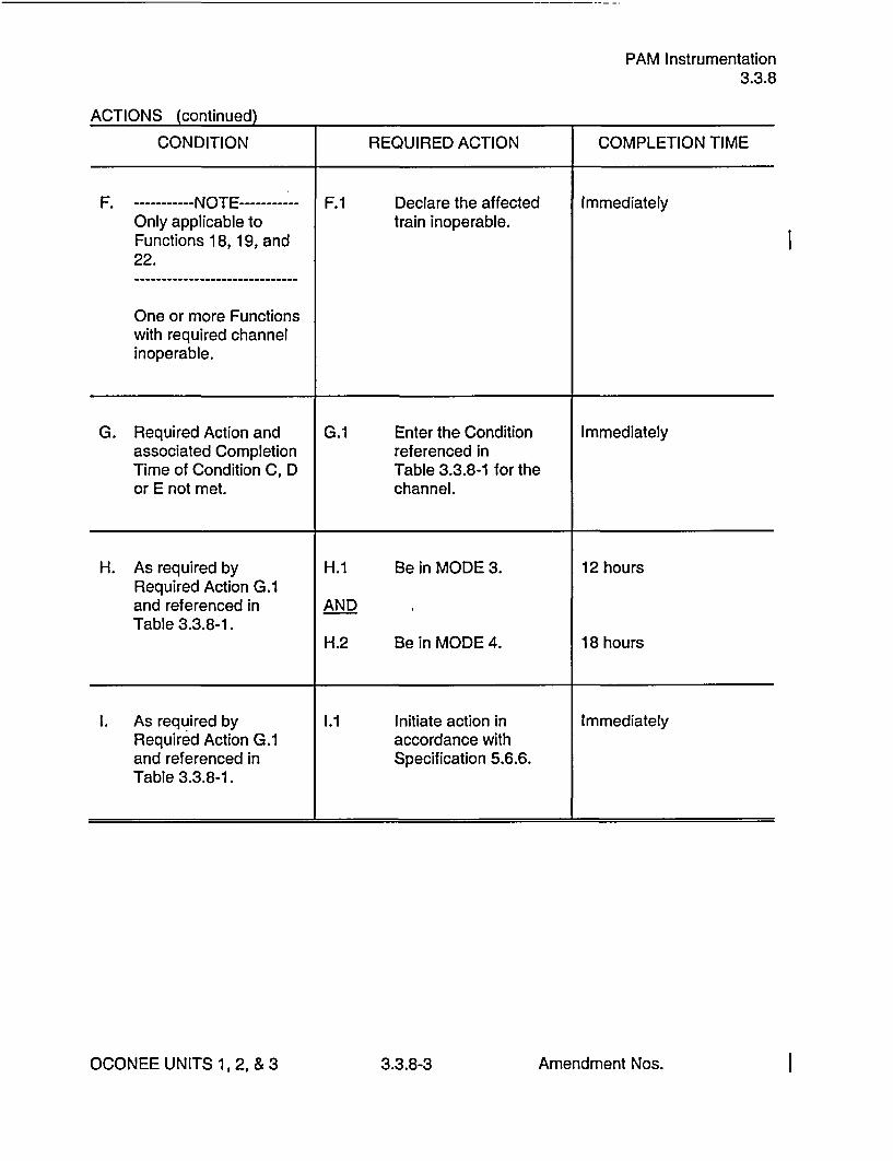
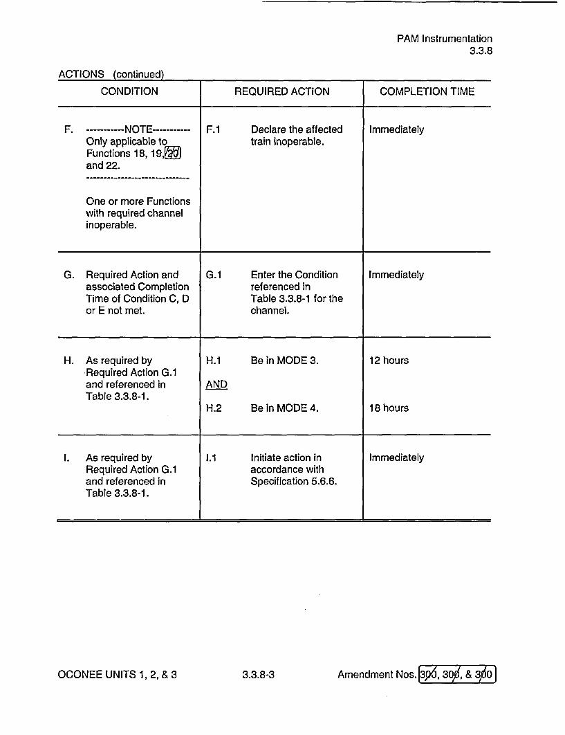
F. ----------- NOTE----------- F.1 Declare the affected ImmediatelyOnly applicable to train inoperable.Functions 18, 19, and22.
One or more Functionswith required channelinoperable.
G. Required Action and G.1 Enter the Condition Immediatelyassociated Completion referenced inTime of Condition C, D Table 3.3.8-1 for theor E not met. channel.
H. As required by H.1 Be in MODE 3. 12 hoursRequired Action G.1and referenced in ANDTable 3.3.8-1.
H.2 Be in MODE 4. 18 hours
I. As required by 1.1 Initiate action in ImmediatelyRequired Action G.1 accordance withand referenced in Specification 5.6.6.Table 3.3.8-1.
I
OCONEE UNITS 1, 2, & 3 3.3.8-3 Amendment Nos. I

PAM Instrumentation3.3.8
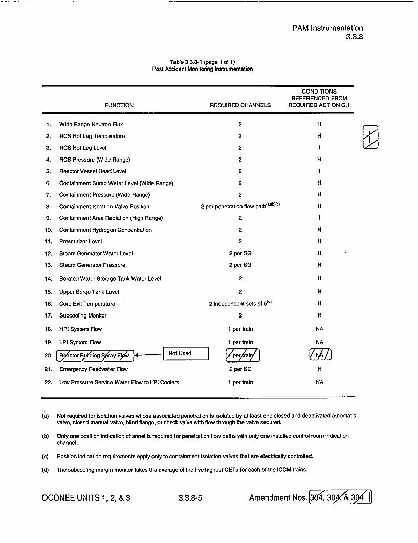
Table 3.3.8-1 (page 1 of 1)Post Accident Monitoring Instrumentation
CONDITIONSREFERENCED FROM
FUNCTION REQUIRED CHANNELS REQUIRED ACTION G.1
1.
2.
3.
4.
5.
6.
7.
8.
9.
10.
11.
12.
13.
14.
15.
16.
17.
18.
19.
20.
21.
22.
Wide Range Neutron Flux
RCS Hot Leg Temperature
RCS Hot Leg Level
RCS Pressure (Wide Range)
Reactor Vessel Head Level
Containment Sump Water Level (Wide Range)
Containment Pressure (Wide Range)
Containment Isolation Valve Position
Containment Area Radiation (High Range)
Containment Hydrogen Concentration
Pressurizer Level
Steam Generator Water Level
Steam Generator Pressure
Borated Water Storage Tank Water Level
Upper Surge Tank Level
Core Exit Temperature
Subcooling Monitor
HPI System Flow
LPI System Flow
Not used
Emergency Feedwater Flow
Low Pressure Service Water Flow to LPI Coolers
2
2
2
2
2
2
2
2 per penetration flow path(anb)(c)
2
2
2
2perSG
2perSG
2
2
2 independent sets of 5(d)
2
1 per train
1 per train
2 per SG
1 per train
H
H
H
H
H
H
H
H
H
H
H
H
H
H
NA
NA
I
H
NA
(a) Not required for Isolation valves whose associated penetration is Isolated by at least one closed and deactivated automaticvalve, closed manual valve, blind flange, or check valve with flow through the valve secured.
(b) Only one position indication channel Is required for penetration flow paths with only one installed control room indicationchannel.
(c) Position indication requirements apply only to containment Isolation valves that are electrically controlled.
(d) The subcooling margin monitor takes the average of the five highest CETs for each of the ICCM trains.
OCONEE UNITS 1, 2, & 3 3.3.8-5 Amendment Nos. I

PAM InstrumentationB 3.3.8
BASES
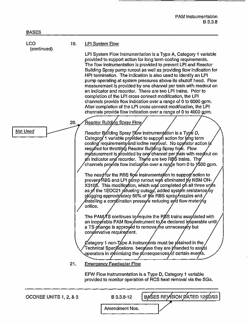
LCO 19. LPI System Flow(continued)
LPI System Flow instrumentation is a Type A, Category 1 variableprovided to support action for long term cooling requirements.The flow instrumentation is provided to prevent LPI and ReactorBuilding Spray pump runout as well as providing flow indication forHPI termination. The indication is also used to identify an LPIpump operating at system pressures above its shutoff head. Flowmeasurement is provided by one channel per train with readout onan indicator and recorder. There are two LPI trains. Prior tocompletion of the LPI cross connect modification, the LPIchannels provide flow indication over a range of 0 to 6000 gpm.After completion of the LPI cross connect modification, the LPIchannels provide flow indication over a range of 0 to 4000 gpm.
20. Not used
21. Emergency Feedwater Flow
EFW Flow instrumentation is a Type D, Category 1 variableprovided to monitor operation of RCS heat removal via the SGs.Two channels provide indication of EFW Flow to each SG over arange of approximately 100 gpm to 1200 gpm. Redundantmonitoring capability is provided by the two independent channelsof instrumentation for each SG. Each flow transmitter provides aninput to a control room indicator. One channel also provides inputto a recorder.
EFW Flow is the primary indication used by the operator to verifythat the EFW System is delivering the correct flow to each SG.However, the primary indication used by the operator to ensure anadequate inventory is SG level.
22. Low Pressure Service Water (LPSW) flow to LPI Coolers
LPSW flow to LPI Coolers is a Type A, Category 1 variable whichis provided to prevent LPSW pump runout and inadequate NPSH.LPSW flow to LPI Coolers is throttled to maintain proper flowbalance in the LPSW System.
OCONEE UNITS 1,2, &3 B 3.3.8-1 2 Amendment Nos. I

PAM InstrumentationB 3.3.8
BASES
LCO 22. Low Pressure Service Water (LPSW) flow to LPI Coolers(continued)
Flow measurement is provided by one channel per train withreadout on an indicator and the plant computer via a qualifiedsignal isolator. The channels provide flow indication over a rangefrom 0-8000 gpm.
APPLICABILITY The PAM instrumentation LCO is applicable in MODES 1, 2, and 3.These variables are related to the diagnosis and preplanned actionsrequired to mitigate accidents and transients. The applicable accidentsand transients are assumed to occur in MODES 1, 2, and 3. InMODES 4, 5, and 6, unit conditions are such that the likelihood of anevent occurring that would require PAM instrumentation is low; therefore,the PAM instrumentation is not required to be OPERABLE in theseMODES.
ACTIONS The ACTIONS are modified by two Notes. Note I is added to theACTIONS to exclude the MODE change restriction of LCO 3.0.4. Thisexception allows entry into an applicable MODE while relying on theACTIONS even though the ACTIONS may eventually require a unitshutdown. This exception is acceptable due to the passive function ofthe instruments, the operator's ability to respond to an accident utilizingalternate instruments and methods, and the low probability of an eventrequiring these instruments.
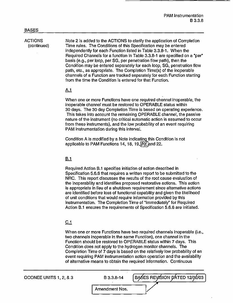
Note 2 is added to the ACTIONS to clarify the application of CompletionTime rules. The Conditions of this Specification may be enteredindependently for each Function listed in Table 3.3.8-1. When theRequired Channels for a function in Table 3.3.8-1 are specified on a 'per'basis (e.g., per loop, per SG, per penetration flow path), then theCondition may be entered separately for each loop, SG, penetration flowpath, etc., as appropriate. The Completion Time(s) of the inoperablechannels of a Function are tracked separately for each Function startingfrom the time the Condition is entered for that Function.
A.1
When one or more Functions have one required channel inoperable, theinoperable channel must be restored to OPERABLE status within30 days. The 30 day Completion Time is based on operating experience.
OCONEE UNITS 1, 2, & 3 B 3.3.8-1 3 Amendment Nos. I

PAM InstrumentationB 3.3.8
BASES
ACTIONS A.1 (continued)
This takes into account the remaining OPERABLE channel, the passivenature of the instrument (no critical automatic action is assumed to occurfrom these instruments), and the low probability of an event requiringPAM instrumentation during this interval.
Condition A is modified by a Note indicating this Condition is notapplicable to PAM Functions 14, 18, 19, and 22.
B.1
Required Action B.1 specifies initiation of action described inSpecification 5.6.6 that requires a written report to be submitted to theNRC. This report discusses the results of the root cause evaluation ofthe inoperability and identifies proposed restorative actions. This actionis appropriate in lieu of a shutdown requirement since alternative actionsare identified before loss of functional capability and given the likelihoodof unit conditions that would require information provided by thisinstrumentation. The Completion Time of "Immediately" for RequiredAction B.1 ensures the requirements of Specification 5.6.6 are initiated.
C.1 I
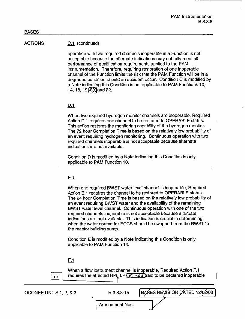
When one or more Functions have two required channels inoperable (i.e.,two channels inoperable in the same Function), one channel in theFunction should be restored to OPERABLE status within 7 days. ThisCondition does not apply to the hydrogen monitor channels. TheCompletion Time of 7 days is based on the relatively low probability of anevent requiring PAM instrumentation action operation and the availabilityof alternative means to obtain the required information. Continuousoperation with two required channels inoperable in a Function is notacceptable because the alternate indications may not fully meet allperformance of qualification requirements applied to the PAMinstrumentation. Therefore, requiring restoration of one inoperablechannel of the Function limits the risk that the PAM Function will be in adegraded condition should an accident occur. Condition C is modified bya Note indicating this Condition is not applicable to PAM Functions 10,14,18,19, and 22.
OCONEE UNITS 1, 2, & 3 B 3.3.8-1 4 Amendment Nos. I

PAM InstrumentationB 3.3.8
BASES
ACTIONS D.1(continued)
When two required hydrogen monitor channels are inoperable, RequiredAction D.1 requires one channel to be restored to OPERABLE status.This action restores the monitoring capability of the hydrogen monitor.The 72 hour Completion Time is based on the relatively low probability ofan event requiring hydrogen monitoring. Continuous operation with tworequired channels inoperable is not acceptable because alternateindications are not available.
Condition D is modified by a Note indicating this Condition is onlyapplicable to PAM Function 10.
E.1
When one required BWST water level channel is inoperable, RequiredAction E.1 requires the channel to be restored to OPERABLE status.The 24 hour Completion Time is based on the relatively low probability ofan event requiring BWST water and the availability of the remainingBWST water level channel. Continuous operation with one of the tworequired channels inoperable is not acceptable because alternateindications are not available. This indication is crucial in determiningwhen the water source for ECCS should be swapped from the BWST tothe reactor building sump. I
Condition E is modified by a Note indicating this Condition is onlyapplicable to PAM Function 14.
F.1
When a flow instrument channel is inoperable, Required Action F.1requires the affected HPI or LPI train to be declared inoperable and therequirements of LCO 3.5.2 or LCO 3.5.3 apply. For Function 22, LPSWflow to LPI coolers, the affected train is the associated LPI train. ForFunction 18, HPI flow, an inoperable flow instrument channel causes theaffected HPI train's automatic function to be inoperable. The HPI traincontinues to be manually OPERABLE provided the HPI dischargecrossover valves and associated flow instruments are OPERABLE.Therefore, HPI is in a condition where one HPI train is incapable of beingautomatically actuated but capable of being manually actuated. Therequired Completion Time for declaring the train(s) inoperable isimmediately. Therefore, LCO 3.5.2 or LCO 3.5.3 is entered immediately,and the Required Actions in the LCOs apply without delay.
OCONEE UNITS 1, 2, & 3 B 3.3.8-1 5 Amendment Nos. I
PAM InstrumentationB 3.3.8
BASES
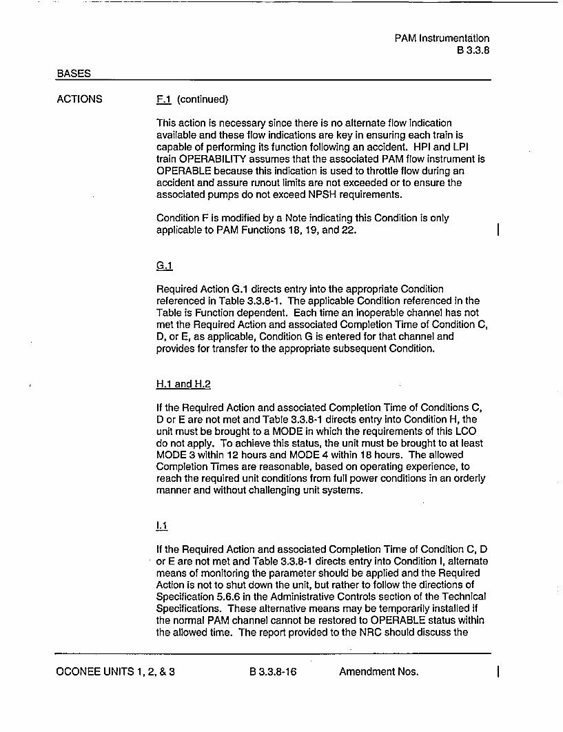
ACTIONS F.1 (continued)
This action is necessary since there is no alternate flow indicationavailable and these flow indications are key in ensuring each train iscapable of performing its function following an accident. HPI and LPItrain OPERABILITY assumes that the associated PAM flow instrument isOPERABLE because this indication is used to throttle flow during anaccident and assure runout limits are not exceeded or to ensure theassociated pumps do not exceed NPSH requirements.
Condition F is modified by a Note indicating this Condition is onlyapplicable to PAM Functions 18, 19, and 22.
G.1
Required Action G.1 directs entry into the appropriate Conditionreferenced in Table 3.3.8-1. The applicable Condition referenced in theTable is Function dependent. Each time an inoperable channel has notmet the Required Action and associated Completion Time of Condition C,D, or E, as applicable, Condition G is entered for that channel andprovides for transfer to the appropriate subsequent Condition.
H.1 and H.2
If the Required Action and associated Completion Time of Conditions C,D or E are not met and Table 3.3.8-1 directs entry into Condition H, theunit must be brought to a MODE in which the requirements of this LCOdo not apply. To achieve this status, the unit must be brought to at leastMODE 3 within 12 hours and MODE 4 within 18 hours. The allowedCompletion Times are reasonable, based on operating experience, toreach the required unit conditions from full power conditions in an orderlymanner and without challenging unit systems.
1.1
If the Required Action and associated Completion Time of Condition C, Dor E are not met and Table 3.3.8-1 directs entry into Condition I, alternatemeans of monitoring the parameter should be applied and the RequiredAction is not to shut down the unit, but rather to follow the directions ofSpecification 5.6.6 in the Administrative Controls section of the TechnicalSpecifications. These alternative means may be temporarily installed ifthe normal PAM channel cannot be restored to OPERABLE status withinthe allowed time. The report provided to the NRC should discuss the
OCONEE UNITS 1, 2, & 3 B 3.3.8-1 6 Amendment Nos. I
PAM InstrumentationB 3.3.8
BASES
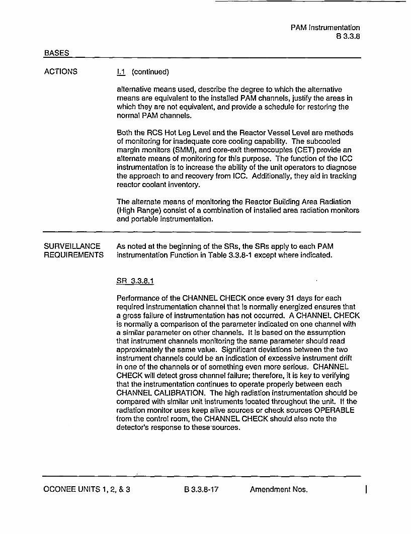
ACTIONS 1.1 (continued)
alternative means used, describe the degree to which the alternativemeans are equivalent to the installed PAM channels, justify the areas inwhich they are not equivalent, and provide a schedule for restoring thenormal PAM channels.
Both the RCS Hot Leg Level and the Reactor Vessel Level are methodsof monitoring for inadequate core cooling capability. The subcooledmargin monitors (SMM), and core-exit thermocouples (CET) provide analternate means of monitoring for this purpose. The function of the ICCinstrumentation is to increase the ability of the unit operators to diagnosethe approach to and recovery from ICC. Additionally, they aid in trackingreactor coolant inventory.
The alternate means of monitoring the Reactor Building Area Radiation(High Range) consist of a combination of installed area radiation monitorsand portable instrumentation.
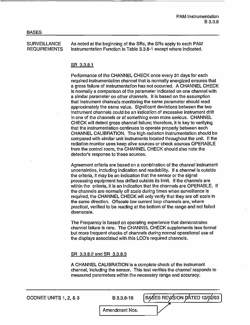
SURVEILLANCE As noted at the beginning of the SRs, the SRs apply to each PAMREQUIREMENTS instrumentation Function in Table 3.3.8-1 except where indicated.
SR 3.3.8.1
Performance of the CHANNEL CHECK once every 31 days for eachrequired instrumentation channel that is normally energized ensures thata gross failure of instrumentation has not occurred. A CHANNEL CHECKis normally a comparison of the parameter indicated on one channel witha similar parameter on other channels. It is based on the assumptionthat instrument channels monitoring the same parameter should readapproximately the same value. Significant deviations between the twoinstrument channels could be an indication of excessive instrument driftin one of the channels or of something even more serious. CHANNELCHECK will detect gross channel failure; therefore, it is key to verifyingthat the instrumentation continues to operate properly between eachCHANNEL CALIBRATION. The high radiation instrumentation should becompared with similar unit instruments located throughout the unit. If theradiation monitor uses keep alive sources or check sources OPERABLEfrom the control room, the CHANNEL CHECK should also note thedetector's response to these sources.
OCONEE UNITS 1, 2, & 3 B 3.3.8-1 7 Amendment Nos. I
PAM InstrumentationB 3.3.8
BASES
SURVEILLANCE SR 3.3.8.1 (continued)REQUIREMENTS
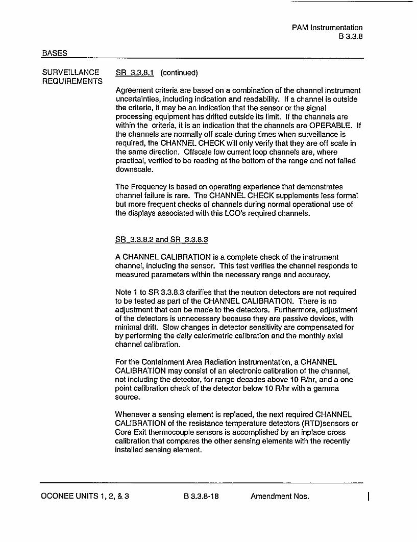
Agreement criteria are based on a combination of the channel instrumentuncertainties, including indication and readability. If a channel is outsidethe criteria, it may be an indication that the sensor or the signalprocessing equipment has drifted outside its limit. If the channels arewithin the criteria, it is an indication that the channels are OPERABLE. Ifthe channels are normally off scale during times when surveillance isrequired, the CHANNEL CHECK will only verify that they are off scale inthe same direction. Offscale low current loop channels are, wherepractical, verified to be reading at the bottom of the range and not faileddownscale.
The Frequency is based on operating experience that demonstrateschannel failure is rare. The CHANNEL CHECK supplements less formalbut more frequent checks of channels during normal operational use ofthe displays associated with this LCO's required channels.
SR 3.3.8.2 and SR 3.3.8.3
A CHANNEL CALIBRATION is a complete check of the instrumentchannel, including the sensor. This test verifies the channel responds tomeasured parameters within the necessary range and accuracy.
Note 1 to SR 3.3.8.3 clarifies that the neutron detectors are not requiredto be tested as part of the CHANNEL CALIBRATION. There is noadjustment that can be made to the detectors. Furthermore, adjustmentof the detectors is unnecessary because they are passive devices, withminimal drift. Slow changes in detector sensitivity are compensated forby performing the daily calorimetric calibration and the monthly axialchannel calibration.
For the Containment Area Radiation instrumentation, a CHANNELCALIBRATION may consist of an electronic calibration of the channel,not including the detector, for range decades above 10 R/hr, and a onepoint calibration check of the detector below 10 R/hr with a gammasource.
Whenever a sensing element is replaced, the next required CHANNELCALIBRATION of the resistance temperature detectors (RTD)sensors orCore Exit thermocouple sensors is accomplished by an inplace crosscalibration that compares the other sensing elements with the recentlyinstalled sensing element.
OCONEE UNITS 1, 2, & 3 B 3.3.8-1 8 Amendment Nos. I
PAM InstrumentationB 3.3.8
BASES
SURVEILLANCE SR 3.3.8.2 and SR 3.3.8.3 (continued)REQUIREMENTS
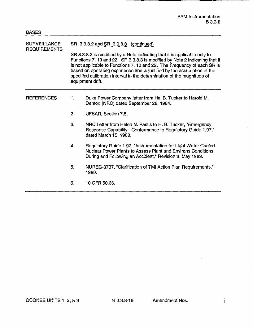
SR 3.3.8.2 is modified by a Note indicating that it is applicable only toFunctions 7, 10 and 22. SR 3.3.8.3 is modified by Note 2 indicating that itis not applicable to Functions 7, 10 and 22. The Frequency of each SR isbased on operating experience and is justified by the assumption of thespecified calibration interval in the determination of the magnitude ofequipment drift.
REFERENCES 1. Duke Power Company letter from Hal B. Tucker to Harold M.Denton (NRC) dated September 28,1984.
2. UFSAR, Section 7.5.
3. NRC Letter from Helen N. Pastis to H. B. Tucker, "EmergencyResponse Capability - Conformance to Regulatory Guide 1.97,"dated March 15,1988.
4. Regulatory Guide 1.97, "Instrumentation for Light Water CooledNuclear Power Plants to Assess Plant and Environs ConditionsDuring and Following an Accident," Revision 3, May 1983.
5. NUREG-0737, "Clarification of TMI Action Plan Requirements,"1980.
6. 10 CFR 50.36.
OCONEE UNITS 1, 2, & 3 B 3.3.8-19 Amendment Nos. I
LPIB 3.5.3
BASES
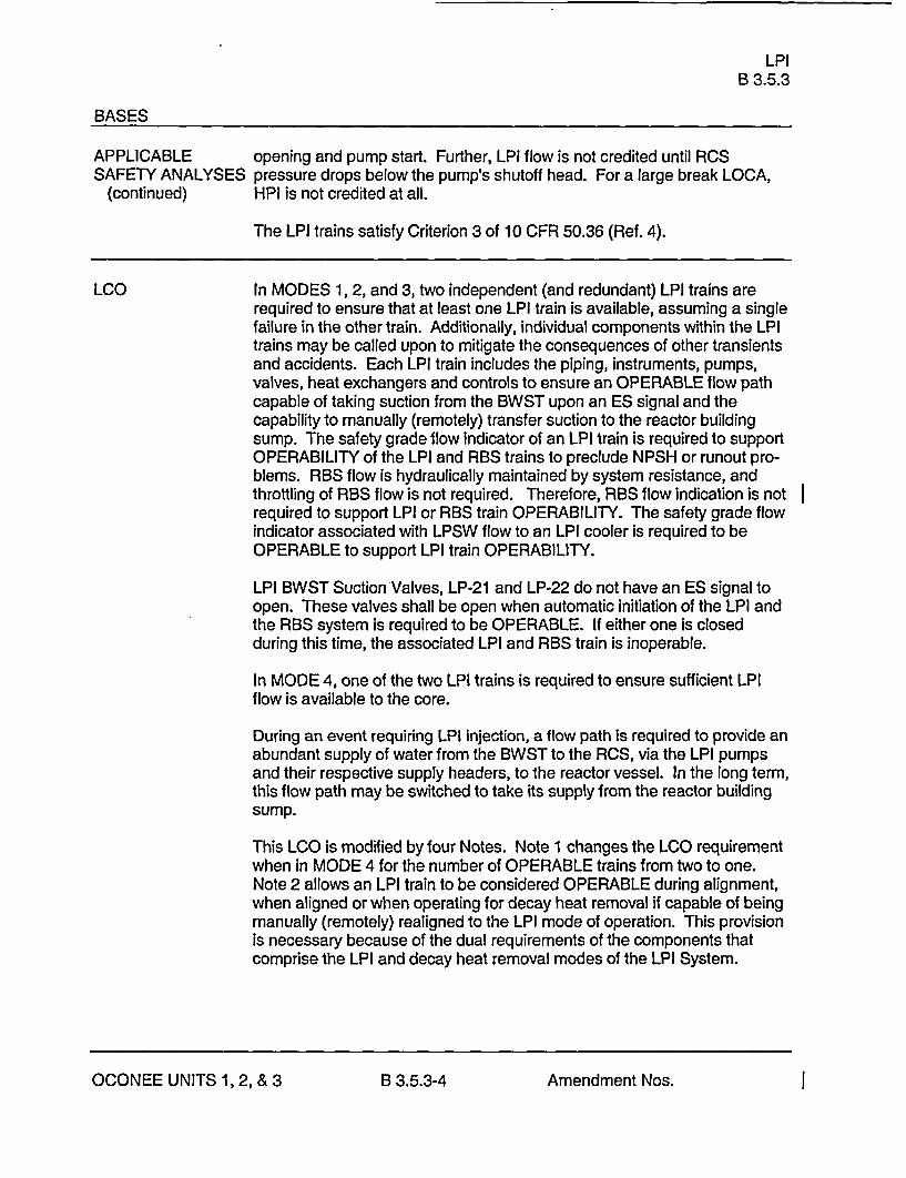
APPLICABLE opening and pump start. Further, LPI flow is not credited until RCSSAFETY ANALYSES pressure drops below the pump's shutoff head. For a large break LOCA,
(continued) HPI is not credited at all.
The LPI trains satisfy Criterion 3 of 10 CFR 50.36 (Ref. 4).
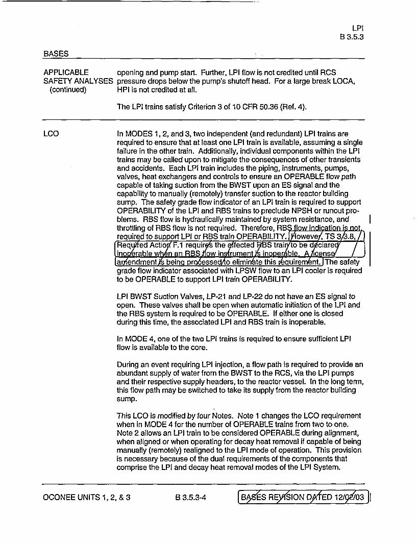
LCO In MODES 1, 2, and 3, two independent (and redundant) LPI trains arerequired to ensure that at least one LPI train is available, assuming a singlefailure in the other train. Additionally, individual components within the LPItrains may be called upon to mitigate the consequences of other transientsand accidents. Each LPI train includes the piping, instruments, pumps,valves, heat exchangers and controls to ensure an OPERABLE flow pathcapable of taking suction from the BWST upon an ES signal and thecapability to manually (remotely) transfer suction to the reactor buildingsump. The safety grade flow indicator of an LPI train is required to supportOPERABILITY of the LPI and RBS trains to preclude NPSH or runout pro-blems. RBS flow is hydraulically maintained by system resistance, andthrottling of RBS flow is not required. Therefore, RBS flow indication is notrequired to support LPI or RBS train OPERABILITY. The safety grade flowindicator associated with LPSW flow to an LPI cooler is required to beOPERABLE to support LPI train OPERABILITY.
LPI BWST Suction Valves, LP-21 and LP-22 do not have an ES signal toopen. These valves shall be open when automatic initiation of the LPI andthe RBS system is required to be OPERABLE. If either one is closedduring this time, the associated LPI and RBS train is inoperable.
In MODE 4, one of the two LPI trains is required to ensure sufficient LPIflow is available to the core.
During an event requiring LPI injection, a flow path is required to provide anabundant supply of water from the BWST to the RCS, via the LPI pumpsand their respective supply headers, to the reactor vessel. In the long term,this flow path may be switched to take its supply from the reactor buildingsump.
This LCO is modified by four Notes. Note 1 changes the LCO requirementwhen in MODE 4 for the number of OPERABLE trains from two to one.Note 2 allows an LPI train to be considered OPERABLE during alignment,when aligned or when operating for decay heat removal if capable of beingmanually (remotely) realigned to the LPI mode of operation. This provisionis necessary because of the dual requirements of the components thatcomprise the LPI and decay heat removal modes of the LPI System.
OCONEE UNITS 1, 2, & 3 B 3.5.3-4 Amendment Nos. I

Reactor Building Spray and Cooling SystemsB 3.6.5
BASES
LCO(continued)
Each reactor building spray train shall include a spray pump, sprayheaders, nozzles, valves, piping, instruments, and controls to ensure anOPERABLE flow path capable of taking suction from the BWST (via theLPI System) upon an Engineered Safeguards Protective System signal andmanually transferring suction to the reactor building sump. TheOPERABILITY of RBS train flow instrumentation is not required forOPERABILITY of the corresponding RBS train because system resistancehydraulically maintains adequate NPSH to the RBS pumps and manualthrottling of RBS flow is not required. During an event, LPI train flow mustbe monitored and controlled to support the RBS train pumps to ensure thatthe NPSH requirements for the RBS pumps are not exceeded. If the flowinstrumentation or the capability to control the flow in a LPI train isunavailable then the associated RBS train's OPERABILITY is affected untilsuch time as the LPI train is restored or the associated LPI pump is placedin a secured state to prevent actuation during an event.
I
Each reactor building cooling train shall include cooling coils, fusibledropout plates or duct openings, an axial vane flow fan, instruments,valves, and controls to ensure an OPERABLE flow path. Valve LPSW-1 08shall be locked open to support system OPERABILITY.
APPLICABILITY In MODES 1, 2, 3, and 4, an accident could cause a release of radioactivematerial to containment and an increase in containment pressure andtemperature, requiring the operation of the reactor building spray trains andreactor building cooling trains.
In MODES 5 and 6, the probability and consequences of these events arereduced due to the pressure and temperature limitations of these MODES.Thus, the Reactor Building Spray System and the Reactor Building CoolingSystem are not required to be OPERABLE in MODES 5 and 6.
ACTIONS The Actions are nrodified by a Note indicating that the provisions ofLCO 3.0.4 do not apply for Unit 2 only. As a result, this allows entry into aMODE or other specified condition in the Applicability with the LCO not metafter performance of a risk assessment addressing inoperable systems andcomponents, consideration of the results, determination of the acceptabilityof entering the MODE or other specified condition in the Applicability, andestablishment of risk management actions, if appropriate.
OCONEE UNITS 1, 2, & 3 B 3.6.5-4 Amendment Nos. I

August 20, 2004
ATTACHMENT 2
MAR.KUP OF TECHNICAL SPECIFICATION
PAM Instrumentation3.3.8
3.3 INSTRUMENTATION
3.3.8 Post Accident Monitoring (PAM) Instrumentation
LCO 3.3.8 The PAM instrumentation for each Function in Table 3.3.8-1 shall beOPERABLE.
APPLICABILITY: MODES 1, 2, and 3.
ACTIONS
1LC3.4inoaplc---ae----------------------------------------------.N1. LCO 3.0.4 is not applicable.
r-�� ---------------------------------------------------
2. Separate Condition entry is allowed for each Function.-- - --- - - -- - - - -- - - -- - - -- - - - -- - - -- - - - -- - - -- - - -- - - - -- - - -- - - -- - - - -- - --.- - -
CONDITION REQUIRED ACTION COMPLETION TIME
A. ----------- NOTE----------- A.1 Restore required 30 daysNot applicable to channel to OPERABLEFunctions 14, 18, 19, status.Mand 22.
One or more Functionswith one requiredchannel inoperable.
B. Required Action and B.1 Initiate action in Immediatelyassociated Completion accordance withTime of Condition A not Specification 5.6.6.met.
(continued)
Amendment Nos. 3ja6, 30,, & W OOCONEE UNITS 1, 2, & 3 -3.3.8-1
PAM Instrumentation3.3.8
ACTIONS (continued)
CONDITION REQUIRED ACTION COMPLETION TIME
C.- NOTE----------- C.1 Restore one channel to 7 daysNot applicable to OPERABLE status.Functions 10, 14, 18,19ffand 22.
One or more Functionswith two requiredchannels inoperable.
D. -----------NOTE----------- D.1 Restore one required 72 hoursOnly applicable to channel to OPERABLEFunction 10. status.
Two required channelsinoperable.
E. -----------NOTE----------- E.1 Restore required 24 hoursOnly applicable to channel to OPERABLEFunction 14. status.
One required channelinoperable.
(continued)
Amendment Nos. 30, 30 , & 3 0OCONEE UNITS 1, 2, & 3 3.3.8-2
PAM Instrumentation3.3.8
ACTIONS (continued)
CONDITION REQUIRED ACTION COMPLETION TIME
F. ----------- NOTE----------- F.1 Declare the affected ImmediatelyOnly applicable to train inoperable.Functions 18, 19and 22.
One or more Functionswith required channelinoperable.
G. Required Action and G.1 Enter the Condition Immediatelyassociated Completion referenced inTime of Condition C, D Table 3.3.8-1 for theor E not met. channel.
H. As required by H.1 Be in MODE 3. 12 hoursRequired Action G.1and referenced in ANDTable 3.3.8-1.
H.2 Be in MODE 4. 18 hours
I. As required by 1.1 Initiate action in ImmediatelyRequired Action G.1 accordance withand referenced in Specification 5.6.6.Table 3.3.8-1.
OCONEE UNITS 1, 2, & 3 3.3.8-3 Amendment Nos. [3 6, 30 , & 3 01
PAM Instrumentation3.3.8
Table 3.3.8-1 (page 1 of 1)Post Accident Monitoring Instrumentation
CONDITIONSREFERENCED FROM
FUNCTION REQUIRED CHANNELS REQUIRED ACTION G.1
1. Wide Range Neutron Flux 2 H
2. RCS Hot Leg Temperature 2 H
3. RCS Hot Leg Level 2 1
4. RCS Pressure (Wide Range) 2 H
5. Reactor Vessel Head Level 2 1
6. Containment Sump Water Level (Wide Range) 2 H
7. Containment Pressure (Wide Range) 2 H
8. Containment Isolation Valve Position 2 per penetration flow path(a)(b)(c) H
9. Containment Area Radiation (High Range) 2 1
10. Containment Hydrogen Concentration 2 H
11. Pressurizer Level 2 H
12. Steam Generator Water Level 2 per SG H
13. Steam Generator Pressure 2 per SG H
14. Borated Water Storage Tank Water Level 2 H
15. Upper Surge Tank Level 2 H
16. Core Exit Temperature 2 Independent sets of 5(d) H
17. Subcooling Monitor 2 H
18. HPI System Flow 1 per train NA
19. LPI System Flow 1 per train NA
20. R Not Used | rai7
21. Emergency Feedwater Flow 2 per SG H
22. Low Pressure Service Water Flow to LPI Coolers 1 per train NA
(a) Not required for Isolation valves whose associated penetration Is isolated by at least one closed and deactivated automaticvalve, closed manual valve, blind flange, or check valve with flow through the valve secured.
(b) Only one position indication channel is required for penetration flow paths with only one installed control room indicationchannel.
(c) Position Indication requirements apply only to containment Isolation valves that are electrically controlled.
(d) The subcooling margin monitor takes the average of the five highest CETs for each of the ICCM trains.
OCONEE UNITS 1, 2, & 3 3.3.8-5 Amendment Nos. W4,30y &39'i
PAM InstrumentationB 3.3.8
BASES
LCO 19. LPI System Flow(continued)
LPI System Flow instrumentation is a Type A, Category 1 variableprovided to support action for long term cooling requirements.The flow instrumentation is provided to prevent LPI and ReactorBuilding Spray pump runout as well as providing flow indication forHPI termination. The indication is also used to identify an LPIpump operating at system pressures above its shutoff head. Flowmeasurement is provided by one channel per train with readout onan indicator and recorder. There are two LPI trains. Prior tocompletion of the LPI cross connect modification, the LPIchannels provide flow indication over a range of 0 to 6000 gpm.After completion of the LPI cross connect modification, the LPIchannels provide flow indication over a range of 0 to 4000 gpm.
20. eactor Buildi Spray Flo
Not Used Reactor Bding Spray F ow instrumen tion is a Ty D,Catego 1 variable pr ided to supp action for ing termcoolin requirement and iodine re oval. No op ator action ireq ed for throttli g Reactor Bui ing Spray fig. Flowm asurement is rovided by on channel per an with rea out on
pindicator anrecorder. Th e are two R trains. Thchannels pro ide flow indic on over a ra e from 0 to 00 gpm.
The nee or the RBS fli instrumenta on to suppo action topreven BS and LPI mp runout w eliminated y NSM ON-X310,. This modific ion, which w completed all three uas the 1 EOC21 fueling outag, added syst i resistanceyp gging approxi ately 50% of tge RBS spray ozzles andnstalling a co ination presse reducingad flow meter'orif ice.
The PAM S continues to equire the S trains ass ciated withan inop rable PAM flow nstrument to e declared i perable untila TS ange is appro d to remove e unnecess ry butcon ervative require ent.
ategory 1 non-T pe A instru nts must be tained in theTechnical Spec ications bec se they are tended to as toperators in nimizing the onsequences f certain eve s.
21. Emergency Feedwater Flow
EFW Flow instrumentation is a Type D, Category I variableprovided to monitor operation of RCS heat removal via the SGs.
OCONEE UNITS 1, 2, & 3 B 3.3.8-12 B ES RE SION)ATED 12//2/03l
|Amendment Nos. |/

PAM InstrumentationB 3.3.8
BASES
LCO 21. Emergency Feedwater Flow (continued)
Two channels provide indication of EFW Flow to each SG over arange of approximately 100 gpm to 1200 gpm. Redundantmonitoring capability is provided by the two independent channelsof instrumentation for each SG. Each flow transmitter provides aninput to a control room indicator. One channel also provides inputto a recorder.
EFW Flow is the primary indication used by the operator to verifythat the EFW System is delivering the correct flow to each SG.However, the primary indication used by the operator to ensure anadequate inventory is SG level.
22. Low Pressure Service Water (LPSW) flow to LPI Coolers
LPSW flow to LPI Coolers is a Type A, Category 1 variable whichis provided to prevent LPSW pump runout and inadequate NPSH.LPSW flow to LPI Coolers is throttled to maintain proper flowbalance in the LPSW System.
Flow measurement is provided by one channel per train withreadout on an indicator and the plant computer via a qualifiedsignal isolator. The channels provide flow indication over a rangefrom 0-8000 gpm.
APPLICABILITY The PAM instrumentation LCO is applicable in MODES 1, 2, and 3.These variables are related to the diagnosis and preplanned actionsrequired to mitigate accidents and transients. The applicable accidentsand transients are assumed to occur in MODES 1, 2, and 3. InMODES 4, 5, and 6, unit conditions are such that the likelihood of anevent occurring that would require PAM instrumentation is low; therefore,the PAM instrumentation is not required to be OPERABLE in theseMODES.
ACTIONS The ACTIONS are modified by two Notes. Note 1 is added to theACTIONS to exclude the MODE change restriction of LCO 3.0.4. Thisexception allows entry into an applicable MODE while relying on theACTIONS even though the ACTIONS may eventually require a unitshutdown. This exception is acceptable due to the passive function ofthe instruments, the operator's ability to respond to an accident utilizingalternate instruments and methods, and the low probability of an eventrequiring these instruments.
OCONEE UNITS 1, 2, & 3 B 3.3.8-13 [ BOES REY(SION)ATED 12/,/2103 l
IAmendment Nos. 1Z
PAM InstrumentationB 3.3.8
BASES
ACTIONS(continued)
Note 2 is added to the ACTIONS to clarify the application of CompletionTime rules. The Conditions of this Specification may be enteredindependently for each Function listed in Table 3.3.8-1. When theRequired Channels for a function in Table 3.3.8-1 are specified on a "per"basis (e.g., per loop, per SG, per penetration flow path), then theCondition may be entered separately for each loop, SG, penetration flowpath, etc., as appropriate. The Completion Time(s) of the inoperablechannels of a Function are tracked separately for each Function startingfrom the time the Condition is entered for that Function.
A.1
When one or more Functions have one required channel inoperable, theinoperable channel must be restored to OPERABLE status within30 days. The 30 day Completion Time is based on operating experience.This takes into account the remaining OPERABLE channel, the passivenature of the instrument (no critical automatic action is assumed to occurfrom these instruments), and the low probability of an event requiringPAM instrumentation during this interval.
Condition A is modified by a Note indicatthis Condition is notapplicable to PAM Functions 14, 18, 19, gand 22.
B.1
Required Action B.1 specifies initiation of action described inSpecification 5.6.6 that requires a written report to be submitted to theNRC. This report discusses the results of the root cause evaluation ofthe inoperability and identifies proposed restorative actions. This actionis appropriate in lieu of a shutdown requirement since alternative actionsare identified before loss of functional capability and given the likelihoodof unit conditions that would require information provided by thisinstrumentation. The Completion Time of 'Immediately" for RequiredAction B.1 ensures the requirements of Specification 5.6.6 are initiated.
C.1
When one or more Functions have two required channels inoperable (i.e.,two channels inoperable in the same Function), one channel in theFunction should be restored to OPERABLE status within 7 days. ThisCondition does not apply to the hydrogen monitor channels. TheCompletion Time of 7 days is based on the relatively low probability of anevent requiring PAM instrumentation action operation and the availabilityof alternative means to obtain the required information. Continuous
OCONEE UNITS 1, 2, & 3 B 3.3.8-14 [BAES REyOIONYATED 12/5003]j
I Amendment Nos. 1. .
PAM InstrumentationB 3.3.8
BASES
ACTIONS C.1 (continued)
operation with two required channels inoperable in a Function is notacceptable because the alternate indications may not fully meet allperformance of qualification requirements applied to the PAMinstrumentation. Therefore, requiring restoration of one inoperablechannel of the Function limits the risk that the PAM Function will be in adegraded condition should an accident occur. Condition C is modified bya Note indicating this Condition is not applicable to PAM Functions 10,14,18, 19,9and 22.
D.1
When two required hydrogen monitor channels are inoperable, RequiredAction D.1 requires one channel to be restored to OPERABLE status.This action restores the monitoring capability of the hydrogen monitor.The 72 hour Completion Time is based on the relatively low probability ofan event requiring hydrogen monitoring. Continuous operation with tworequired channels inoperable is not acceptable because alternateindications are not available.
Condition D is modified by a Note indicating this Condition is onlyapplicable to PAM Function 10.
E.1
When one required BWST water level channel is inoperable, RequiredAction E.1 requires the channel to be restored to OPERABLE status.The 24 hour Completion Time is based on the relatively low probability ofan event requiring BWST water and the availability of the remainingBWST water level channel. Continuous operation with one of the tworequired channels inoperable is not acceptable because alternateindications are not available. This indication is crucial in determiningwhen the water source for ECCS should be swapped from the BWST tothe reactor building sump.
Condition E is modified by a Note indicating this Condition is onlyapplicable to PAM Function 14.
F.1
When a flow instrument channel is inoperable, Required Action F.1[E7] requires the affected HPI LPl Or U rain to be declared inoperable
OCONEE UNITS 1, 2, & 3 B 3.3.8-15 B ES REV ION ,5NATED 12/9&l03
|Amendment Nos.

PAM InstrumentationB 3.3.8
BASES
ACTIONS F.1 (continued) o
and the requirements of LCO 3.5.2iLCO 3.5.4;9L) 3j 5 apply. ForFunction 22, LPSW flow to LPI coolers, the aff train is theassociated LPI train. For Function 18, HPI flow, an inoperable flowinstrument channel causes the affected HPI train's automatic function tobe inoperable. The HPI train continues to be manually OPERABLEprovided the HPI discharge crossover valves and associated flowinstruments are OPERABLE. Therefore, HPI is in a condition where oneHPI train is incapable of being automatically actuated but capable of mbeing manually actuated. The required Completion Time for orthe train(s) inoperable is immediately. Therefore, LCO 3.5.0LCO 3.5.36I(LCQ 34i.5Jis entered immediately, and the Required Actions in theLCOs apply without delay. This action is necessary since there is noalternate flow indication available and these flow indications are key inensuring each train is capable of performing its function following anaccident. HPI and LPI train OPERABILITY assumes that the associatedPAM flow instrument is OPERABLE because this indication is used tothrottle flow during an accident and assure runout limits are not exceededor to ensure the associated pumps do not exceed NPSH requirements.
For Fun on 20, the RBS tra'associated with inoperable RB flowinstru nt must be declar inoperable even t ough it is no Ion ernee d to support throttl g flow because thi action is require byT hnical Specificatio
Condition F is modified by a Note indicating this Condition is onlyapplicable to PAM Functions 18, 19,9 and 22.
G.1
Required Action G.1 directs entry into the appropriate Conditionreferenced in Table 3.3.8-1. The applicable Condition referenced in theTable is Function dependent. Each time an inoperable channel has notmet the Required Action and associated Completion Time of Condition C,D, or E, as applicable, Condition G is entered for that channel andprovides for transfer to the appropriate subsequent Condition.
OCONEE UNITS 1, 2, & 3 B 3.3.8-16 [B ES REVION6/ATED 12/ 03
Amendment Nos.

PAM InstrumentationB 3.3.8
BASES
ACTIONS H.1 and H.2 (continued)
If the Required Action and associated Completion Time of Conditions C,D or E are not met and Table 3.3.8-1 directs entry into Condition H, theunit must be brought to a MODE in which the requirements of this LCOdo not apply. To achieve this status, the unit must be brought to at leastMODE 3 within 12 hours and MODE 4 within 18 hours. The allowedCompletion Times are reasonable, based on operating experience, toreach the required unit conditions from full power conditions in an orderlymanner and without challenging unit systems.
1.1
If the Required Action and associated Completion Time of Condition C, Dor E are not met and Table 3.3.8-1 directs entry into Condition I, alternatemeans of monitoring the parameter should be applied and the RequiredAction is not to shut down the unit, but rather to follow the directions ofSpecification 5.6.6 in the Administrative Controls section of the TechnicalSpecifications. These alternative means may be temporarily installed ifthe normal PAM channel cannot be restored to OPERABLE status withinthe allowed time. The report provided to the NRC should discuss thealternative means used, describe the degree to which the alternativemeans are equivalent to the installed PAM channels, justify the areas inwhich they are not equivalent, and provide a schedule for restoring thenormal PAM channels.
Both the RCS Hot Leg Level and the Reactor Vessel Level are methodsof monitoring for inadequate core cooling capability. The subcooledmargin monitors (SMM), and core-exit thermocouples (CET) provide analternate means of monitoring for this purpose. The function of the ICCinstrumentation is to increase the ability of the unit operators to diagnosethe approach to and recovery from ICC. Additionally, they aid in trackingreactor coolant inventory.
The alternate means of monitoring the Reactor Building Area Radiation(High Range) consist of a combination of installed area radiation monitorsand portable instrumentation.
OCONEE UNITS 1, 2, & 3 B 3.3.8-17 (BYES REV ION51 ATED 12/ 03
Amendment Nos.
PAM InstrumentationB 3.3.8
BASES
SURVEILLANCE As noted at the beginning of the SRs, the SRs apply to each PAMREQUIREMENTS instrumentation Function in Table 3.3.8-1 except where indicated.
SR 3.3.8.1
Performance of the CHANNEL CHECK once every 31 days for eachrequired instrumentation channel that is normally energized ensures thata gross failure of instrumentation has not occurred. A CHANNEL CHECKis normally a comparison of the parameter indicated on one channel witha similar parameter on other channels. It is based on the assumptionthat instrument channels monitoring the same parameter should readapproximately the same value. Significant deviations between the twoinstrument channels could be an indication of excessive instrument driftin one of the channels or of something even more serious. CHANNELCHECK will detect gross channel failure; therefore, it is key to verifyingthat the instrumentation continues to operate properly between eachCHANNEL CALIBRATION. The high radiation instrumentation should becompared with similar unit instruments located throughout the unit. If theradiation monitor uses keep alive sources or check sources OPERABLEfrom the control room, the CHANNEL CHECK should also note thedetector's response to these sources.
Agreement criteria are based on a combination of the channel instrumentuncertainties, including indication and readability. If a channel is outsidethe criteria, it may be an indication that the sensor or the signalprocessing equipment has drifted outside its limit. If the channels arewithin the criteria, it is an indication that the channels are OPERABLE. Ifthe channels are normally off scale during times when surveillance isrequired, the CHANNEL CHECK will only verify that they are off scale inthe same direction. Offscale low current loop channels are, wherepractical, verified to be reading at the bottom of the range and not faileddownscale.
The Frequency is based on operating experience that demonstrateschannel failure is rare. The CHANNEL CHECK supplements less formalbut more frequent checks of channels during normal operational use ofthe displays associated with this LCO's required channels.
SR 3.3.8.2 and SR 3.3.8.3
A CHANNEL CALIBRATION is a complete check of the instrumentchannel, including the sensor. This test verifies the channel responds tomeasured parameters within the necessary range and accuracy.
OCONEE UNITS 1, 2, & 3 B 3.3.8-18 [BOES REV IONYATED 12/ 030
| Amendment Nos.

PAM InstrumentationB 3.3.8
BASES
SURVEILLANCE SR 3.3.8.2 and SR 3.3.8.3 (continued)REQUIREMENTS
Note 1 to SR 3.3.8.3 clarifies that the neutron detectors are not requiredto be tested as part of the CHANNEL CALIBRATION. There is noadjustment that can be made to the detectors. Furthermore, adjustmentof the detectors is unnecessary because they are passive devices, withminimal drift. Slow changes in detector sensitivity are compensated forby performing the daily calorimetric calibration and the monthly axialchannel calibration.
For the Containment Area Radiation instrumentation, a CHANNELCALIBRATION may consist of an electronic calibration of the channel,not including the detector, for range decades above 10 R/hr, and a onepoint calibration check of the detector below 10 R/hr with a gammasource.
Whenever a sensing element is replaced, the next required CHANNELCALIBRATION of the resistance temperature detectors (RTD)sensors orCore Exit thermocouple sensors is accomplished by an inplace crosscalibration that compares the other sensing elements with the recentlyinstalled sensing element.
SR 3.3.8.2 is modified by a Note indicating that it is applicable only toFunctions 7, 10 and 22. SR 3.3.8.3 is modified by Note 2 indicating that itis not applicable to Functions 7, 10 and 22. The Frequency of each SR isbased on operating experience and is justified by the assumption of thespecified calibration interval in the determination of the magnitude ofequipment drift.
REFERENCES 1. Duke Power Company letter from Hal B. Tucker to Harold M.Denton (NRC) dated September 28, 1984.
2. UFSAR, Section 7.5.
3. NRC Letter from Helen N. Pastis to H. B. Tucker, 'EmergencyResponse Capability - Conformance to Regulatory Guide 1.97,"dated March 15, 1988.
4. Regulatory Guide 1.97, "Instrumentation for Light Water CooledNuclear Power Plants to Assess Plant and Environs ConditionsDuring and Following an Accident," Revision 3, May 1983.
OCONEE UNITS 1, 2, &3 B 3.3.8-19 |BOES REV IONYATED 12/030l
Amendment Nos. |/
PAM InstrumentationB 3.3.8
BASES
REFERENCES 5. NUREG-0737, "Clarification of TMI Action Plan Requirements,"(continued) 1980.
6. 10 CFR 50.36.
OCONEE UNITS 1, 2, & 3 B 3.3.8-20 [BA4ES REYf'SIONJ/ATED 12/p6I03
|Amendment Nos. 1
LPIB 3.5.3
BASES
APPLICABLE opening and pump start. Further, LPI flow is not credited until RCSSAFETY ANALYSES pressure drops below the pump's shutoff head. For a large break LOCA,
(continued) HPI is not credited at all.
The LPI trains satisfy Criterion 3 of 10 CFR 50.36 (Ref. 4).
LCO In MODES 1, 2, and 3, two independent (and redundant) LPI trains arerequired to ensure that at least one LPI train is available, assuming a singlefailure in the other train. Additionally, individual components within the LPItrains may be called upon to mitigate the consequences of other transientsand accidents. Each LPI train includes the piping, instruments, pumps,valves, heat exchangers and controls to ensure an OPERABLE flow pathcapable of taking suction from the BWST upon an ES signal and thecapability to manually (remotely) transfer suction to the reactor buildingsump. The safety grade flow indicator of an LPI train is required to supportOPERABILITY of the LPI and RBS trains to preclude NPSH or runout pro-blems. RBS flow is hydraulically maintained by system resistance, andthrottling of RBS flow is not required. Therefore, RB§ flow irequirAd to support LPI or FBS train OPERABILITY. lowev TS 3/3.8/Req4ed ActioX F.1 requires the qffected WS trair/>to be dpclareinocperable when an RBS f'low instrument i's inoDerAble. A Licens,ariendmentjzs being prgiessecao elimirr/ate this r/equiren-knt, I The safetygrade flow indicator associated with LPSW flow to an LPI cooler is requiredto be OPERABLE to support LPI train OPERABILITY.
LPI BWST Suction Valves, LP-21 and LP-22 do not have an ES signal toopen. These valves shall be open when automatic initiation of the LPI andthe RBS system is required to be OPERABLE. If either one is closedduring this time, the associated LPI and RBS train is inoperable.
In MODE 4, one of the two LPI trains is required to ensure sufficient LPIflow is available to the core.
During an event requiring LPI injection, a flow path is required to provide anabundant supply of water from the BWST to the RCS, via the LPI pumpsand their respective supply headers, to the reactor vessel. In the long term,this flow path may be switched to take its supply from the reactor buildingsump.
This LCO is modified by four Notes. Note 1 changes the LCO requirementwhen in MODE 4 for the number of OPERABLE trains from two to one.Note 2 allows an LPI train to be considered OPERABLE during alignment,when aligned or when operating for decay heat removal if capable of beingmanually (remotely) realigned to the LPI mode of operation. This provisionis necessary because of the dual requirements of the components thatcomprise the LPI and decay heat removal modes of the LPI System.
OCONEE UNITS 1, 2, & 3 B 3.5.3-4 OB87ES REySION DfED 12/I03

Reactor Building Spray and Cooling SystemsB 3.6.5
BASES
LCO(continued)
Each reactor building spray train shall include a spray pump, sprayheaders, nozzles, valves, piping, instruments, and controls to ensure anOPERABLE flow path capable of taking suction from the BWST (via theLPI System) upon an Engineered Safeguards Protective System signal andmanually transferring suction to the reactor building sump. TheOPERABILITY of RBS train flow instrumentation is not required forOPERABILITY of the corresponding RBS train because system resistancehydraulically maintains adequate NPsH to the RBS pumps and manualthrottling of RBS flow is not required. I Hovy/ever, To 3.3.8,Akequireh ActiqfiF.1 r aies the Af4ected UStafto b ecl rd i oerble whn thRBSfo instrument is inprb A lcnse mendet is bna/prc/essed to~dliminate this reqylreme1t6g During an event, LPI train flowmust be monitored and controlled to support the RBS train pumps toensure that the NPSH requirements for the RBS pumps are not exceeded.If the flow instrumentation or the capability to control the flow in a LPI trainis unavailable then the associated RBS train's OPERABILITY is affecteduntil such time as the LPI train is restored or the associated LPI pump isplaced in a secured state to prevent actuation during an event.
Each reactor building cooling train shall include cooling coils, fusibledropout plates or duct openings, an axial vane flow fan, instruments,valves, and controls to ensure an OPERABLE flow path. Valve LPSW-108shall be locked open to support system OPERABILITY.
APPLICABILITY In MODES 1, 2, 3, and 4, an accident could cause a release of radioactivematerial to containment and an increase in containment pressure andtemperature, requiring the operation of the reactor building spray trains andreactor building cooling trains.
In MODES 5 and 6, the probability and consequences of these events arereduced due to the pressure and temperature limitations of these MODES.Thus, the Reactor Building Spray System and the Reactor Building CoolingSystem are not required to be OPERABLE in MODES 5 and 6.
ACTIONS The Actions are modified by a Note indicating that the provisions ofLCO 3.0.4 do not apply for Unit 2 only. As a result, this allows entry into aMODE or other specified condition in the Applicability with the LCO not metafter performance of a risk assessment addressing inoperable systems andcomponents, consideration of the results, determination of the acceptabilityof entering the MODE or other specified condition in the Applicability, andestablishment of risk management actions, if appropriate.
OCONEE UNITS 1, 2, & 3 B 3.6.5-4 [BAYS REVIXION D1/fED 07A4/04j I
I Amendment Nos. VZ

August 20, 2004Attachment 3Page 1
Attachment 3Technical Justification
Overview
Over the past three outages, Duke modified the ReactorBuilding Spray (RBS) System on each Oconee unit to improvepost-accident RBS operation. The modification eliminates theneed to manually throttle RBS flow rate within 15 minutes ofaccident mitigation during the injection phase of post-accident operation, eliminates the need to manually throttleRBS flow rate prior to switching to the RBES, and improvesthe accuracy of installed instrumentation for pump testing.
The proposed amendment revises Technical Specification (TS)3.3.8, "Post Accident Monitoring Instrumentation," toeliminate TS requirements associated with the ReactorBuilding Spray (RBS) flow instruments commensurate with theimportance of their revised post accident function.
Description of the Technical Specification Change
The proposed change revises TS 3.3.8, TS Bases 3.3.8, 3.5.3 &3.6.5.
TS 3.3.8 - Post Accident Monitoring Instrumentation
Technical Specification 3.3.8 requires one RBS flowinstrument channel per train be OPERABLE when in MODES 1, 2,and 3. With the required channel inoperable, ACTION Frequires the affected RBS train to be declared inoperableimmediately. The proposed TS change removes the RBS flowfunction from Table 3.3.8-1 thereby eliminating the TSrequirements for the RBS flow instrument channels. ConditionA, C and F Notes are modified to remove reference to Function20 (RBS flow). The Bases for TS 3.3.8 is modifiedaccordingly.
TS 3.5.3 Bases - Low Pressure InjectionTS 3.6.5 Bases - Reactor Building Spray and Cooling Systems
The LCO Bases currently requires the affected RBS train to bedeclared inoperable when the RBS flow instrument is

August 20, 2004Attachment 3Page 2
inoperable. The recently completed RBS modificationeliminates the need to manually throttle RBS flow rate within15 minutes of accident mitigation during the injection phaseof post-accident operation and eliminates the need tomanually throttle RBS flow rate prior to switching to theRBES. As such, the requirement to declare the traininoperable has been eliminated and the LCO Bases for 3.5.3and 3.6.5 have been modified accordingly.
Justification for Change
The RBS system has been recently modified to preclude pumprunout; therefore, the flow instrument is only needed tomonitor system operation. Prior to the modification, the RBSflow indication was needed to allow the operator to throttleRBS flow to prevent RBS and LPI pump runout during certainaccident scenarios. As such, the Required Action ofdeclaring the affected RBS train inoperable when the flowinstrument is inoperable is conservative (and no longerappropriate) and needs to be eliminated. There are alternatemeans to verify that the RBS is in operation, such as,verifying the RBS pump and valve status.
With this modification, the RBS flow instrument is onlyneeded to monitor operation of the RBS System. PerRegulatory Guide (RG) 1.97, Revision 3, Table 3, thisvariable is Type D, Category 2. During conversion toImproved Standard Technical Specifications, Duke was requiredto include all Type A and Category 1 instruments identifiedin the NRC RG 1.97 Safety Evaluation Report for Oconee in TSTable 3.3.8-1. Since the RBS flow instrument is no longer aType A or Category 1 variable, Duke proposes to remove theRBS flow instrument from the table.
The RBS System was modified as follows:* The existing flow metering orifice in each RBS header
was replaced with a combination pressure break down andflow metering orifice,
* 50% of the active RBS spray nozzles were plugged toassist in reducing the RBS header flow rates, to limitthe pressure drop across the combination orifice toprevent cavitation, and to maintain pressure drop acrossthe remaining spray nozzles in order to provide adequate
August 20, 2004Attachment 3Page 3
spray coverage area and spray droplet size forcontainment atmospheric washing effects, andHigh accuracy RBS pump differential pressure localindicators were installed, RBS flow transmitters werereplaced, and the RBS flow indicators were re-scaled.
The components installed by this modification meet or exceedthe existing design, material and construction standards.The redundancy and separation of the two independent trainswere maintained. Although there was a change in thedelivered RBS design flow, the effect on system performanceis within the required parameters for the RBS System to meetits intended event mitigation functions. Duke analysesdemonstrated that the modification has no adverse effects onthe RBS system's ability to meet its required designfunctions, and that there are no new safety issues involvedby this modification. The analyses also demonstrated thatthe modification did not have an adverse effect on overallsystem performance or on RBS pump performance due to flowrestrictions or increased system pressures.
Prior to the modification, the RBS flow7 instruments wereclassified as Regulatory Guide 1.97 Category 1 Type A. TypeA variables are defined as those variables which aremonitored to provide the primary information required topermit the Control Room operator to take specific manuallycontrolled actions for which no automatic control is providedand that are required for safety systems to accomplish theirsafety functions for design basis accidents. Primaryinformation is defined as that which is essential for thedirect accomplishment of the specified safety functions; itdoes not include those variables associated with contingencyaction which may also be identified in written procedures.This modification eliminates the need to throttle the RBSsystem during event mitigation. Since throttling is nolonger required to assure that the RBS System accomplishesits safety function for design basis accidents, the flowinstruments are no longer RG 1.97 Category 1, Type A. Theseflow instruments only provide information to indicate theoperation of an individual safety system; therefore, theyhave been re-classified as Category 2, Type D variablesconsistent with RG 1.97.
August 20, 2004Attachment 4Page 1
Attachment 4No Significant Hazards Consideration
Pursuant to 10 CFR 50.91, Duke Energy Corporation (Duke) hasmade the determination that this amendment request involves aNo Significant Hazards Consideration by applying thestandards established by the NRC regulations in 10 CFR 50.92.This ensures that operation of the facility in accordancewith the proposed amendment would not:
(1) Involve a significant increase in the probability orconsequences of an accident previously evaluated:
Duke proposes to remove the RBS flow instrument fromTechnical Specification Table 3.3.8-1 based on a changein its purpose due to recent modifications completed atOconee. The TS 3.3.8 requirement to declare the affectRBS System train inoperable is conservative (andinappropriate) when the associated RBS flow instrumentis inoperable. Due to recent plant modifications, theRBS flow instruments are no longer needed to allow theoperator to throttle flow to preclude RBS pump runoutpost accident. The revised post accident function ofthis PAM instrument is to provide information to indicatethe operation of the RBS System. There are alternatemeans to verify that the RBS is in operation, such as,verifying the RBS pump and valve status. The failure ofan RBS flow instrument has no impact on the probabilityof an accident analyzed in the UFSAR. The RBS flowinstrument is no longer needed to mitigate theconsequences of an accident analyzed in the UFSAR. Assuch, the proposed LAR does not involve a significantincrease in the probability or consequences of anaccident previously evaluated.
(2) Create the possibility of a new or different kind ofaccident from any kind of accident previously evaluated:
Duke proposes to remove the RBS flow instrument fromTechnical Specification Table 3.3.8-1 based on a changein its purpose due to recent modifications completed atOconee. The TS 3.3.8 requirement to declare the affectRBS System train inoperable is conservative (and
August 20, 2004Attachment 4Page 2
inappropriate) when the associated RBS flow instrumentis inoperable. Due to recent plant modifications, theRBS flow instruments are no longer needed to allow theoperator to throttle flow to preclude RBS pump runoutpost accident. These changes do not alter the nature ofevents postulated in the Safety Analysis Report nor dothey introduce any unique precursor mechanisms.Therefore, the proposed amendment will not create thepossibility of a new or different kind of accident fromany accident previously evaluated.
(3) Involve a significant reduction in a margin of safety.
The proposed TS changes do not unfavorably affect anyplant safety limits, set points, or design parameters.The changes also do not unfavorably affect the fuel, fuelcladding, RCS, or containment integrity. Therefore, theproposed TS change, which changes TS requirementsassociated with revised PAM function of the RBS flowinstrument channels, does not involve a significantreduction in the margin of safety.
Duke has concluded, based on the above, that there are nosignificant hazards considerations involved in this amendmentrequest.
August 20, 2004Attachment 5Page 1
ATTACHMENT 5
Environmental Assessment
Pursuant to 10 CFR 51.22(b), an evaluation of the licenseamendment request (LAR) has been performed to determinewhether or not it meets the criteria for categoricalexclusion set forth in 10 CFR 51.22(c)9 of the regulations.The LAR does not involve:
1) A significant hazards consideration.
This conclusion is supported by the determination of nosignificant hazards contained in Attachment 4.
2) A significant change in the types or significantincrease in the amounts of any effluents that may bereleased offsite.
This LAR will not change the types or amounts of anyeffluents that may be released offsite.
3) A significant increase in the individual or cumulativeoccupational radiation exposure.
This LAR will not increase the individual or cumulativeoccupational radiation exposure.
In summary, this LAR meets the criteria set forth in 10 CFR51.22 (c)9 of the regulations for categorical exclusion froman environmental impact statement.