1 dual mass flywheel - schaeffler group · pdf filevariation results from the discrete piston...
TRANSCRIPT
5
Advanced Development of Dual Mass Flywheel (DMFW) Design - Noise Control for Today's Automobiles Dr.-Ing. Albert Albers
Introduction The clutch system in a vehicle performs two main functions:
• Power interruption and modulation during start up and when shifting
• Reduction of rotational vibrations in the drive train induced by engine irregularities
During the LuK Clutch Symposium, LuK will introduce some new developments which successfully fulfill these functions for our customers.
The following presentation will illustrate a cross-section of development efforts aimed at reducing engine-induced rotational vibrations in the drive train.
Rotational vibrations affect durability of the drive train components and create
• Gear rattle
• Body boom
• Tip-in/back-out vibrations
These factors produce considerable noise and a loss in driving comfort.
The main cause of these rotational vibrations is variation in torque. This variation results from the discrete piston combustion cycle of the engine as a function of the ignition frequency.
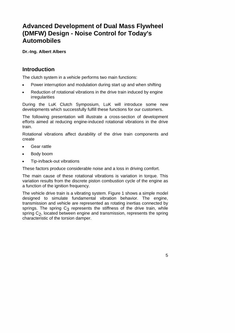
The vehicle drive train is a vibrating system. Figure 1 shows a simple model designed to simulate fundamental vibration behavior. The engine, transmission and vehicle are represented as rotating inertias connected by springs. The spring C3 represents the stiffness of the drive train, while spring C2, located between engine and transmission, represents the spring characteristic of the torsion damper.
6
Such a system has two vibrations modes. The first mode, with a natural frequency of between 2 and 10 Hz, is known as the tip-in/back-out reaction. This is generally excited by a driver-induced load change.
The second mode, where the transmission inertia vibrates against engine and vehicle, has a natural frequency of 40 - 80 Hz with conventional torsion dampers. This is a typical cause of gear rattle.
engine transmission vehicle
vibration model
mode 1surging
f = 2 - 10 Hz
mode 2noise
f = 40 - 80 Hz clutch discf = 7,5 - 15 Hz DFC/DMFW
1
22
J3J2J1
C2 C3
Figure 1: Vehicle drive train with vibration modes
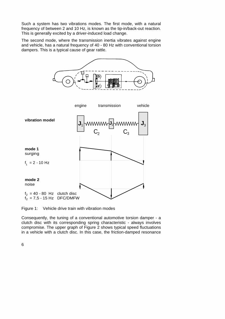
Consequently, the tuning of a conventional automotive torsion damper - a clutch disc with its corresponding spring characteristic - always involves compromise. The upper graph of Figure 2 shows typical speed fluctuations in a vehicle with a clutch disc. In this case, the friction-damped resonance
7
is located at around 1700 rpm. Further damping of this resonance leads to a worsening of the hypercritical isolation of rotational vibrations (at speeds higher than the resonance).
conventional system
DMFW
speed [rpm]1000 2000 3000
100
200
0
speed [rpm]1000 2000 3000
100
200
0
transmission
engine
transmission, friction damping low
transmission, friction damping high
engine
peak
pea
k sp
eed
ampl
itude
[r
pm]
peak
pea
k sp
eed
ampl
itude
[r
pm]
Figure 2: Torsional vibration isolation with conventional clutch disc and dual mass flywheel (DMFW)
The goal of torsion damper development is to keep the torsional vibrations induced by the engine as far as possible from the rest of the drive train.
8
A conventional system only satisfies this requirement at high engine speeds, because the attainable torsion damper spring rates lead to natural frequencies which are always within the normal driving range.
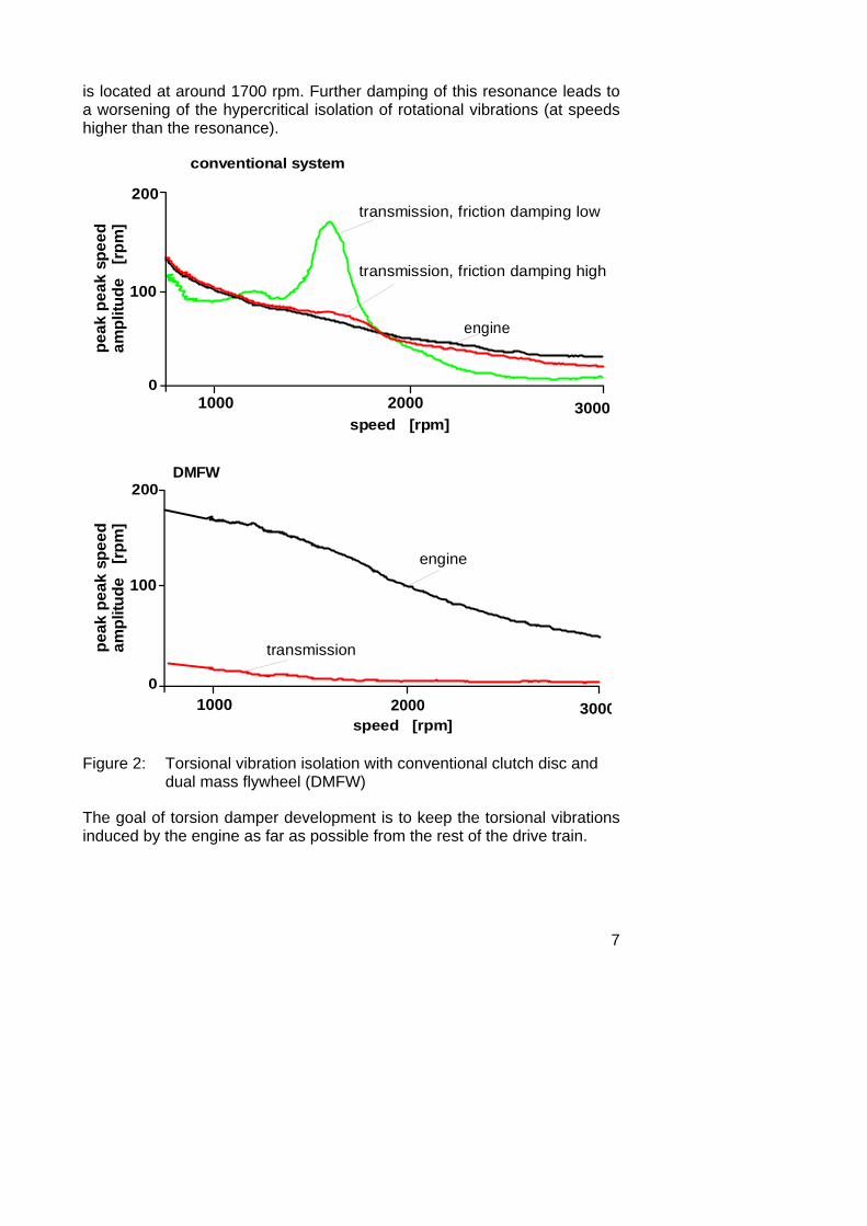
This unsatisfactory situation led to the development of a new torsion damper concept - the dual mass flywheel (DMFW). This design shifts part of the flywheel inertia to the transmission input shaft and drastically lowers the torsion damper spring rate by introducing new spring designs (Figure 3), thus reducing the resonance speed to very low engine speeds. Figure 2, lower graph, shows the hypercritical isolation of rotational engine vibrations (starting from idle speed).
model design
vehicletrans-mission
engine+ flywheel
clutchdisc
engine transmission
engine+ DMFW
clutchdisc
Figure 3: Principle of the dual mass flywheel
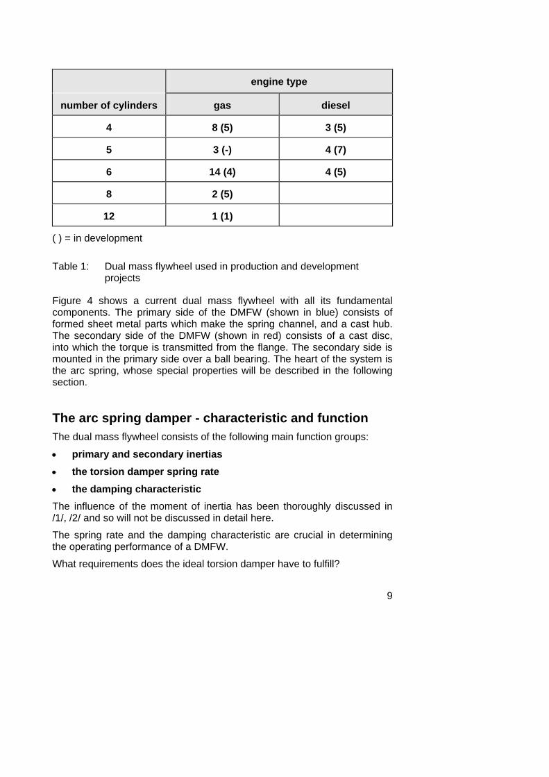
Improvements in driving comfort achieved by the dual mass flywheel, together with low-cost designs resulting from goal-oriented, value-analized development, has led to the increased popularity of this system. Currently the LuK dual mass flywheel is used by ten car manufacturers in approximately 80 different models, thus covering a wide range of engines, as shown in Table 1.
9
engine type
number of cylinders gas diesel
4 8 (5) 3 (5)
5 3 (-) 4 (7)
6 14 (4) 4 (5)
8 2 (5)
12 1 (1)
( ) = in development
Table 1: Dual mass flywheel used in production and development projects
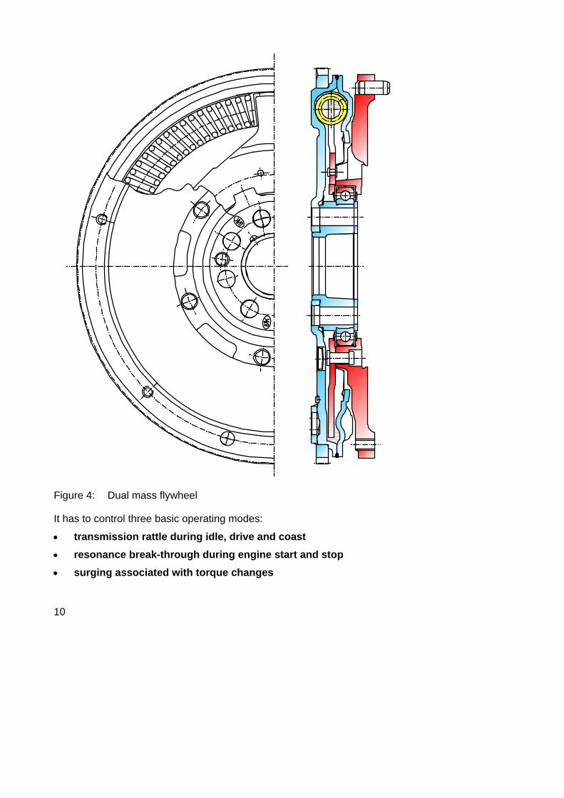
Figure 4 shows a current dual mass flywheel with all its fundamental components. The primary side of the DMFW (shown in blue) consists of formed sheet metal parts which make the spring channel, and a cast hub. The secondary side of the DMFW (shown in red) consists of a cast disc, into which the torque is transmitted from the flange. The secondary side is mounted in the primary side over a ball bearing. The heart of the system is the arc spring, whose special properties will be described in the following section.
The arc spring damper - characteristic and function The dual mass flywheel consists of the following main function groups:
• primary and secondary inertias • the torsion damper spring rate • the damping characteristic The influence of the moment of inertia has been thoroughly discussed in /1/, /2/ and so will not be discussed in detail here.
The spring rate and the damping characteristic are crucial in determining the operating performance of a DMFW.
What requirements does the ideal torsion damper have to fulfill?
10
Figure 4: Dual mass flywheel
It has to control three basic operating modes:
• transmission rattle during idle, drive and coast • resonance break-through during engine start and stop • surging associated with torque changes
11
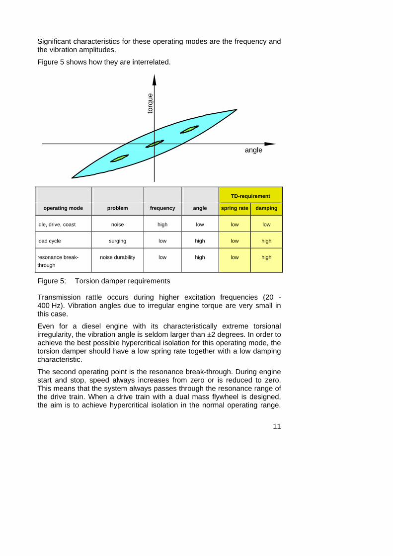
Significant characteristics for these operating modes are the frequency and the vibration amplitudes.
Figure 5 shows how they are interrelated.
torq
ueangle
TD-requirement
operating mode problem frequency angle spring rate damping
idle, drive, coast noise high low low low
load cycle surging low high low high
resonance break-through
noise durability low high low high
Figure 5: Torsion damper requirements
Transmission rattle occurs during higher excitation frequencies (20 - 400 Hz). Vibration angles due to irregular engine torque are very small in this case.
Even for a diesel engine with its characteristically extreme torsional irregularity, the vibration angle is seldom larger than ±2 degrees. In order to achieve the best possible hypercritical isolation for this operating mode, the torsion damper should have a low spring rate together with a low damping characteristic.
The second operating point is the resonance break-through. During engine start and stop, speed always increases from zero or is reduced to zero. This means that the system always passes through the resonance range of the drive train. When a drive train with a dual mass flywheel is designed, the aim is to achieve hypercritical isolation in the normal operating range,
12
i.e. engine speeds above 700 rpm. This means that the development goal is to achieve maximum reduction of the resonance speed.
The resonance break-through is characterized by low frequency vibrations together with a large vibration angle, because the vibration angle of the engine increases in association with decreasing speed. In this case, the torsion damper design requires a low spring rate with a high damping characteristic in order to avoid resonance magnification while passing through the resonance range.
Load cycling is characterized by low frequency vibrations at large vibration angles. In this case the damper requirements call for the lowest possible spring rate and a high damping characteristic. Sudden excitations of the drive train result in large wind-up angles coupled with high friction damping in the torsion damper. This method dissipates the energy of the free natural vibrations in order to reduce the vibration amplitudes.
Figure 5 represents an idealized damper characteristic designed to meet these requirements, i.e. produce a low spring rate and a high damping for large vibration angles. It also shows that the damping is very low for small vibration angles.
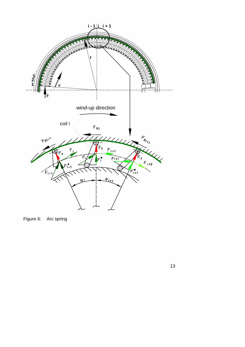
LuK dual mass flywheels contain an arc spring as the main element in order to achieve suitable spring rates and damping characteristics. Arc spring principles are illustrated in Figure 6.
In order to best use the available space, a coil spring with a large number of coils is inserted into a semicircular channel. In the DMFW, the coils of this arc spring are supported by support races mounted in the spring channel in the DMFW. When a load is applied to the spring, the movement of the coils along the support races produce friction, creating the damping. The contact surfaces of the arc spring are lubricated with grease.
The enlarged area in Figure 6 shows the load equilibrium on one coil i of the arc spring.
As the spring load is transmitted along its curved line of action, a normal reaction Fi* is created at the contact surface of each coil. In addition to this, there is a speed-dependent centrifugal force FZ. The sum of these two loads produces the normal reaction force, which in turn produces the friction load FRi for each coil.
13
i - 1 i i + 1
123
r
wind-up direction
..
coil i
F
ϕ
Figure 6: Arc spring
14
CwCw Cw
F1 F2 F3 F4
μ
ϕ <∧
ϕ >∧
Fi
F
F
F1
F1
F2
F2
F3
F3
F4
F4
Fi
Fi
F
F1
F2
F3
F4
i
m
j = 0Ù
F = f ( c e n t r i f u g a l f o r c e , d e f le c t io n a n g le , to r q u e )i
Figure 7: Arc spring damper function
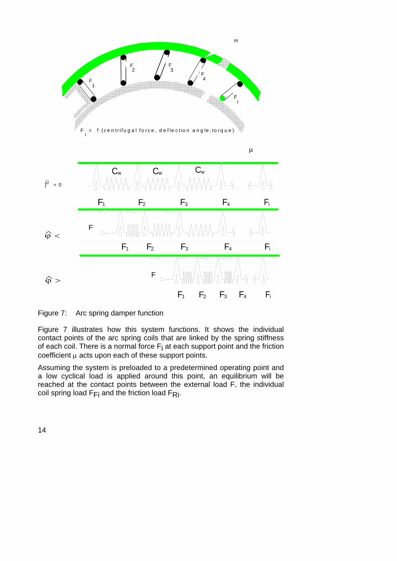
Figure 7 illustrates how this system functions. It shows the individual contact points of the arc spring coils that are linked by the spring stiffness of each coil. There is a normal force Fi at each support point and the friction coefficient μ acts upon each of these support points.
Assuming the system is preloaded to a predetermined operating point and a low cyclical load is applied around this point, an equilibrium will be reached at the contact points between the external load F, the individual coil spring load FFi and the friction load FRi.
15
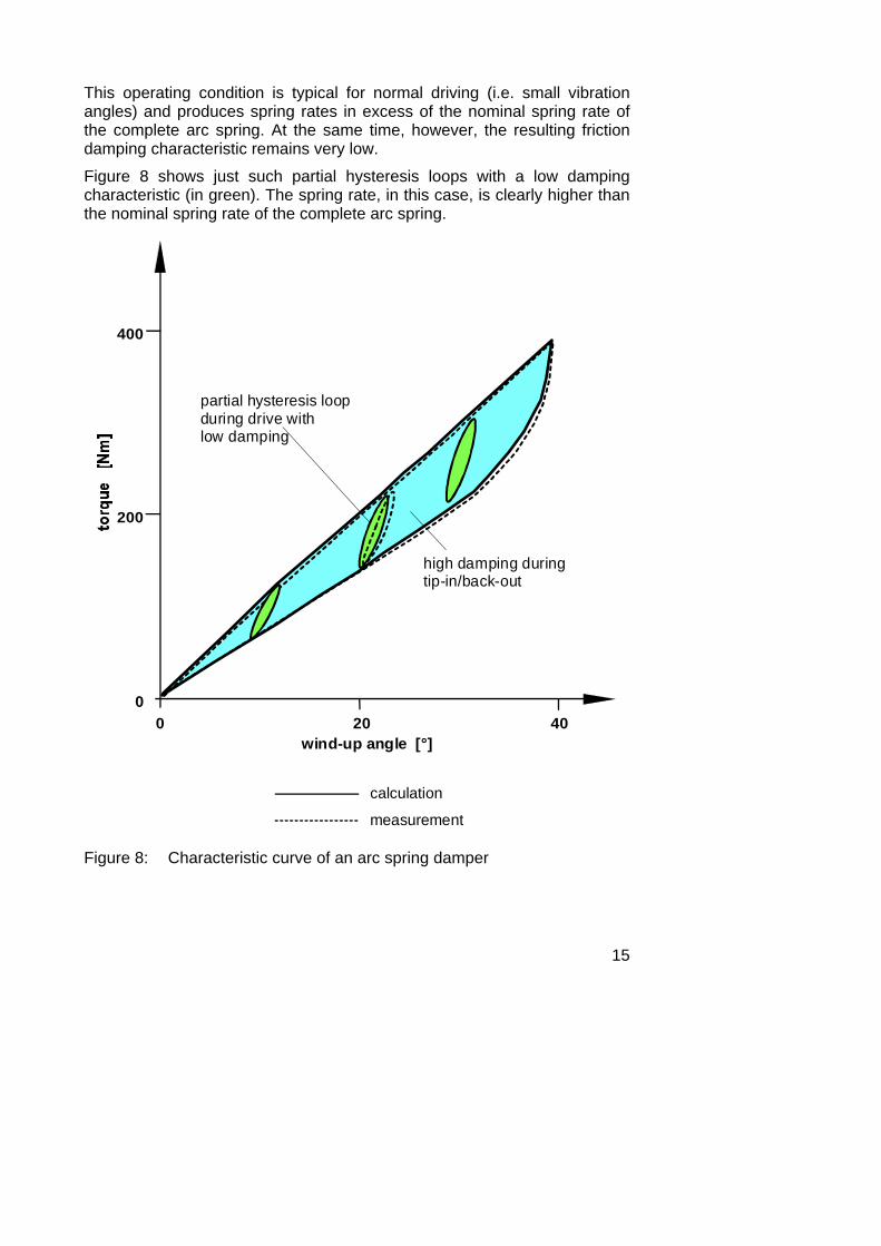
This operating condition is typical for normal driving (i.e. small vibration angles) and produces spring rates in excess of the nominal spring rate of the complete arc spring. At the same time, however, the resulting friction damping characteristic remains very low.
Figure 8 shows just such partial hysteresis loops with a low damping characteristic (in green). The spring rate, in this case, is clearly higher than the nominal spring rate of the complete arc spring.
partial hysteresis loopduring drive withlow damping
high damping duringtip-in/back-out
wind-up angle [°]
calculation
measurement
0 20 40
400
200
0
Figure 8: Characteristic curve of an arc spring damper
16
When large vibration angles occur in the second operating mode as is typical for tip-in/back-out or resonance break-through, all coils of the arc spring become active. This results in a reduced spring rate together with high damping (as shown by the cross-hatched area in Figure 8). Figure 8 also shows the close match between the measured curve and the curve calculated using the method shown above.
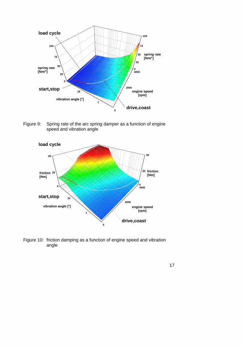
The dependence of spring rate and friction damping on engine speed and vibration angle for a special DMFW is shown in Figures 9 and 10.
Figure 9 shows that for an increasing speed and a decreasing vibration angle, the spring rate of the arc spring damper increases (because of the deactivation of the coils). The diagram also shows the engine performance curve with the vibration angle as a function of velocity for drive/coast (in red) and for start/stop (in yellow). The curve represents actual operating points for a specific 2.5 l Diesel engine.
Figure 10 shows the corresponding friction damping pattern. It can be seen that the torsion damper friction increases with increased engine speed. But unlike the spring rate, the friction damping characteristic decreases sharply with reduced vibration angle. Again the reason is that some of the arc spring coils are deactivated.
In-vehicle performance is determined by a combination of spring rate and damping.
17
0
2000
4000
engine speed[rpm]
1
10
vibration angle [°]
0
25
50
75
100
spring rate[Nm/°]
0
25
50
75
100
spring rate[Nm/°]
start,stop
drive,coast
load cycle
Figure 9: Spring rate of the arc spring damper as a function of engine speed and vibration angle
0
2000
4000
engine speed[rpm]1
10
vibration angle [°]
0
25
50
friction[Nm]
0
25
50
friction[Nm]
drive,coast
start,stop
load cycle
Figure 10: friction damping as a function of engine speed and vibration angle
18
1
10
vibration angle [°]
0
2000
4000
engine speed [rpm]
0
0.5
1
magni-ficationfactor [-]
0
0.5
1
magni-ficationfactor [-]
start,stop
drive,coast
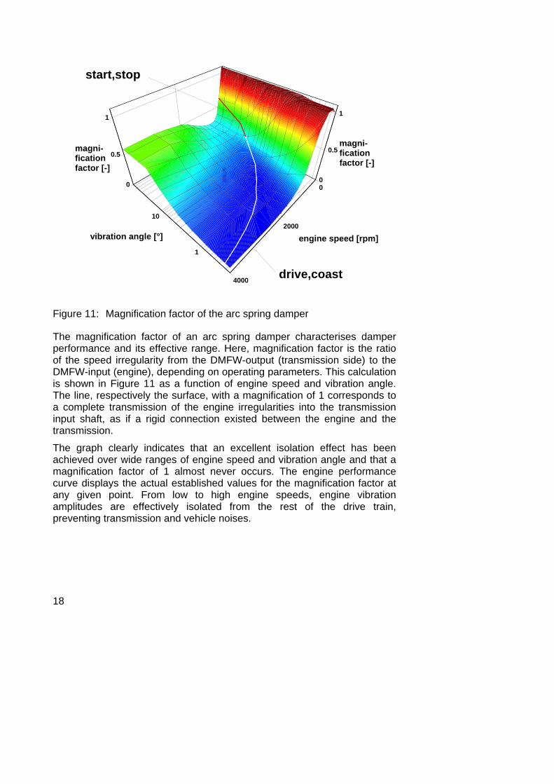
Figure 11: Magnification factor of the arc spring damper
The magnification factor of an arc spring damper characterises damper performance and its effective range. Here, magnification factor is the ratio of the speed irregularity from the DMFW-output (transmission side) to the DMFW-input (engine), depending on operating parameters. This calculation is shown in Figure 11 as a function of engine speed and vibration angle. The line, respectively the surface, with a magnification of 1 corresponds to a complete transmission of the engine irregularities into the transmission input shaft, as if a rigid connection existed between the engine and the transmission.
The graph clearly indicates that an excellent isolation effect has been achieved over wide ranges of engine speed and vibration angle and that a magnification factor of 1 almost never occurs. The engine performance curve displays the actual established values for the magnification factor at any given point. From low to high engine speeds, engine vibration amplitudes are effectively isolated from the rest of the drive train, preventing transmission and vehicle noises.
19
0 0,25 0,5 0,75
400
800
1200
0
0
-20
20
40
0 0,25 0,5 0,75time [s]
torsion damper angle
time [s]
DMFW wind-up angle
transmission
engine
speed
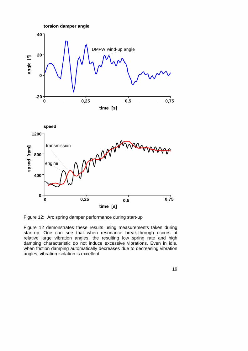
Figure 12: Arc spring damper performance during start-up
Figure 12 demonstrates these results using measurements taken during start-up. One can see that when resonance break-through occurs at relative large vibration angles, the resulting low spring rate and high damping characteristic do not induce excessive vibrations. Even in idle, when friction damping automatically decreases due to decreasing vibration angles, vibration isolation is excellent.
20
In summary, it is apparent that the arc spring damper easily meets all the requirements shown in Figure 5 for an ideal torsion damper, even if its characteristic curve does not match the ideal curve in Figure 5 at first sight. The seemingly contradictory requirements are met without the addition of costly design elements. At the same time the arc spring contains a self-regulating mechanism that automatically establishes an efficient combination of spring rate and damping.
Irregularities are isolated up to high engine speeds, and negative influences on tip-in/back-out performance are avoided by superimposing lower spring rates with high damping at large vibration angles.
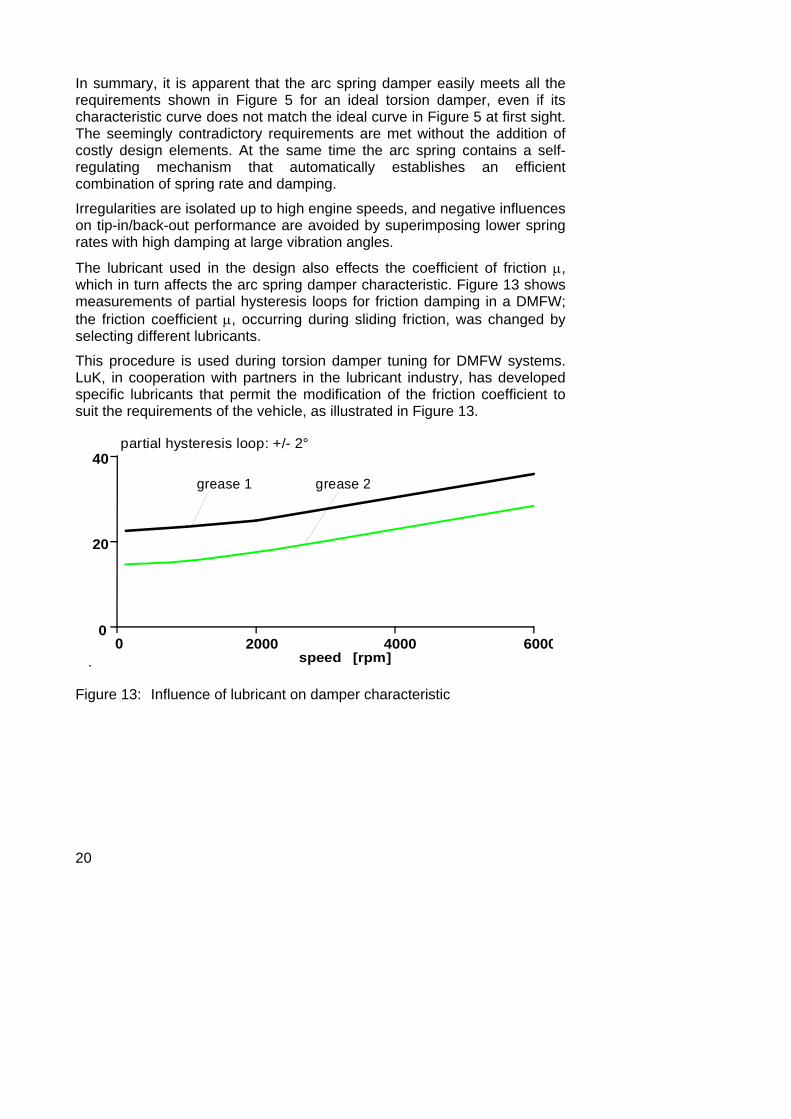
The lubricant used in the design also effects the coefficient of friction μ, which in turn affects the arc spring damper characteristic. Figure 13 shows measurements of partial hysteresis loops for friction damping in a DMFW; the friction coefficient μ, occurring during sliding friction, was changed by selecting different lubricants.
This procedure is used during torsion damper tuning for DMFW systems. LuK, in cooperation with partners in the lubricant industry, has developed specific lubricants that permit the modification of the friction coefficient to suit the requirements of the vehicle, as illustrated in Figure 13.
. speed [rpm]
0
20
40
0 2000 4000 6000
grease 1 grease 2
partial hysteresis loop: +/- 2°
Figure 13: Influence of lubricant on damper characteristic
21
Damper concepts As explained in the previous chapter, customizing the spring rate and damping characteristic has a decisive effect on the performance of the dual mass flywheel. The arc spring damper represents the ideal cost-effective solution for most vehicle drive trains.
There are exceptions, however, where vehicle tuning reveals special problems that require supplements to the arc spring system.
The three basic solutions for these special problem are as follows:
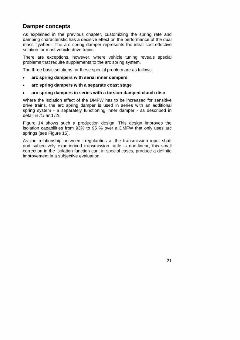
• arc spring dampers with serial inner dampers • arc spring dampers with a separate coast stage • arc spring dampers in series with a torsion-damped clutch disc Where the isolation effect of the DMFW has to be increased for sensitive drive trains, the arc spring damper is used in series with an additional spring system - a separately functioning inner damper - as described in detail in /1/ and /2/.
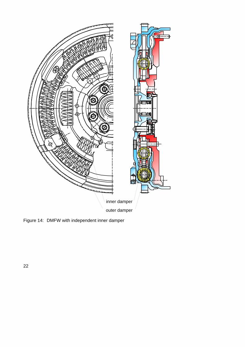
Figure 14 shows such a production design. This design improves the isolation capabilities from 93% to 95 % over a DMFW that only uses arc springs (see Figure 15).
As the relationship between irregularities at the transmission input shaft and subjectively experienced transmission rattle is non-linear, this small correction in the isolation function can, in special cases, produce a definite improvement in a subjective evaluation.
22
inner damper
outer damper
Figure 14: DMFW with independent inner damper
23
1000 2000 30000
60
120
180
1000 2000 30000
10
20
30
speed [rpm]
speed [rpm]
primary inertia
secondary inertia without ID
without inner damperwith inner damper
secondary inertia with ID
Zoom
peak
pea
k sp
eed
ampl
itude
[rpm
]pe
ak p
eak
spee
dam
plitu
de [r
pm]
Figure 15: Engine and transmission speed irregularities using a DMFW with and without an independent inner damper (IID)
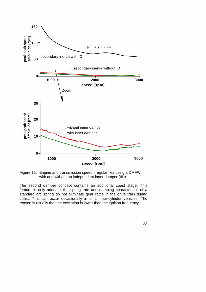
The second damper concept contains an additional coast stage. This feature is only added if the spring rate and damping characteristic of a standard arc spring do not eliminate gear rattle in the drive train during coast. This can occur occasionally in small four-cylinder vehicles. The reason is usually that the excitation is lower than the ignition frequency.
24
FEM-calculationstress pattern
Figure 16: DMFW with flange spring
25
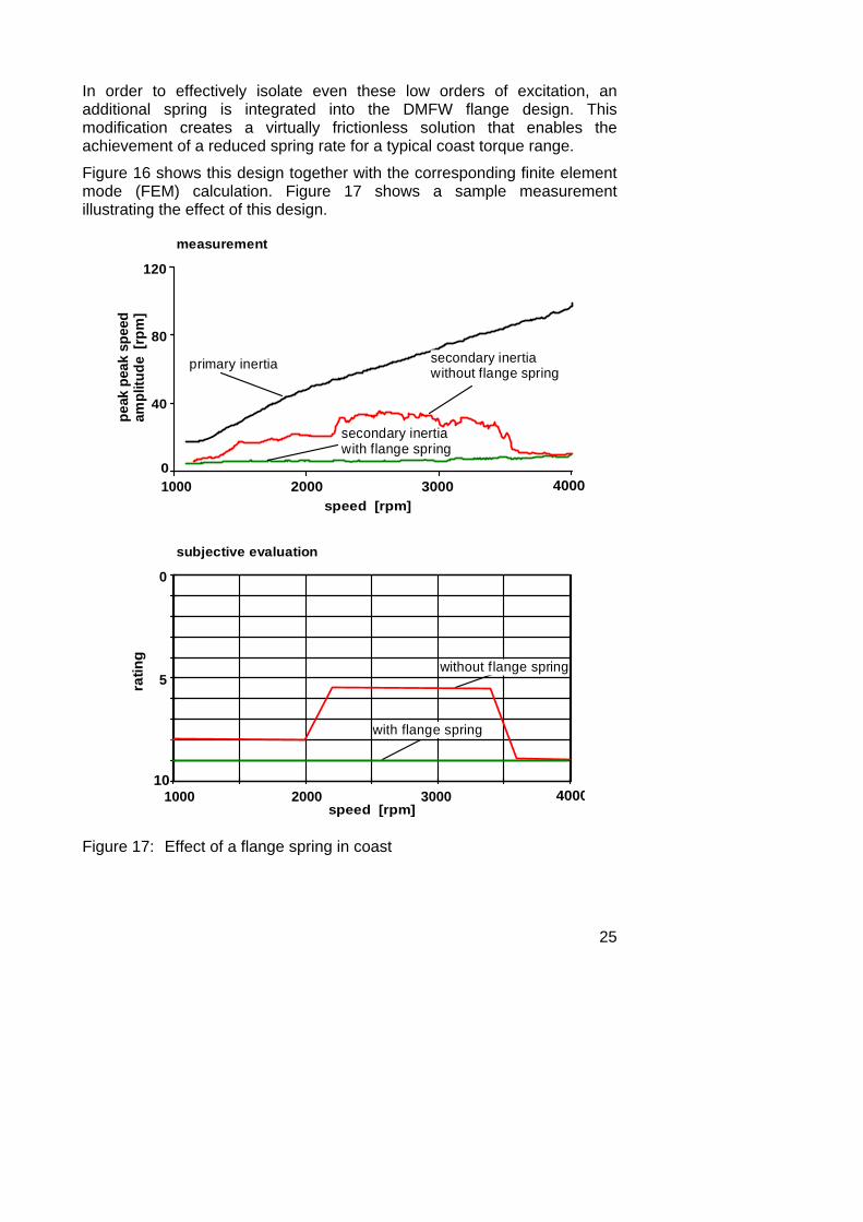
In order to effectively isolate even these low orders of excitation, an additional spring is integrated into the DMFW flange design. This modification creates a virtually frictionless solution that enables the achievement of a reduced spring rate for a typical coast torque range.
Figure 16 shows this design together with the corresponding finite element mode (FEM) calculation. Figure 17 shows a sample measurement illustrating the effect of this design.
secondary inertiawith flange spring
0
5
101000 2000 3000 4000
ratin
g
speed [rpm]
1000 2000 3000 40000
40
80
120
speed [rpm]
measurement
subjective evaluation
primary inertia secondary inertiawithout flange spring
peak
pea
k sp
eed
ampl
itude
[rp
m]
without flange spring
with flange spring
Figure 17: Effect of a flange spring in coast
26
mode 1 4 ÷ 8 Hz, noise
mode 2 6 ÷ 15 Hz, DMFW resonance
mode 3 80 ÷ 120 Hz, engine noise
transmission +differential
primaryinertia
secondaryinertia
vehicle
C2 C3 C4
C2 C3 C4
largeslightwithout
influence onnatural frequency
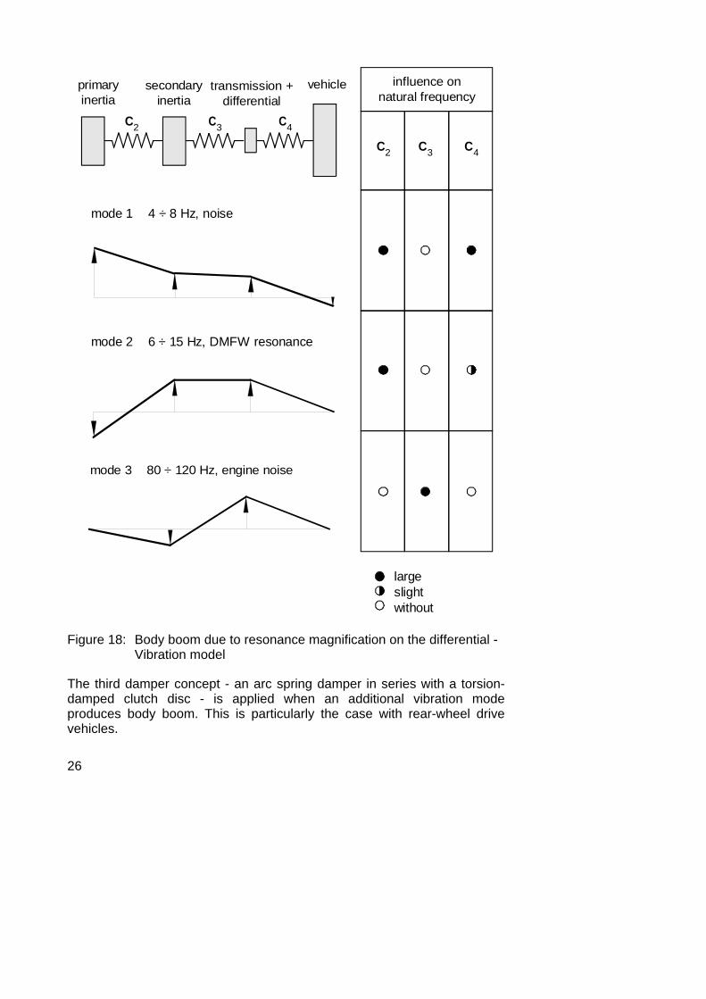
Figure 18: Body boom due to resonance magnification on the differential - Vibration model
The third damper concept - an arc spring damper in series with a torsion-damped clutch disc - is applied when an additional vibration mode produces body boom. This is particularly the case with rear-wheel drive vehicles.
27
Figure 18 shows the relationship among these various factors. An additional torsional inertia was added to the vibration model. This represents the inertia of transmission, drive shaft and differential. In this model, the spring rate C3 is mainly determined by the torsional stiffness of the transmission input shaft.
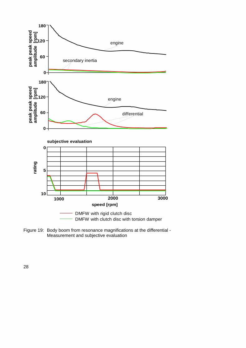
Specific combinations of parameters while driving will produce resonance. This can be detected and measured as rotational vibration at the differential (see Figure 19). This rotational vibration induces the body boom as previously stated. Figures 18 and 19 show that it is virtually impossible to influence this natural frequency by altering the spring rate in the dual mass flywheel.
By designing a torsion damper disc with a customized, relatively high spring rate it is possible to introduce the desired change in the effective stiffness C3. This moves the natural frequency outside the driving range, which eliminates body boom effectively. LuK has also used these solutions in special applications.
In summary, the arc spring damper provides the optimum solution for almost all applications. Modular supplements to the system are only necessary in special cases in order to achieve further optimization of the torsion damper function.
28
0
60
120
180
0
60
120
180
subjective evaluation
1000 2000 3000speed [rpm]
10
5
0
ratin
g
DMFW with clutch disc with torsion damperDMFW with rigid clutch disc
engine
engine
secondary inertia
differential
peak
pea
k sp
eed
ampl
itude
[rp
m]
peak
pea
k sp
eed
ampl
itude
[rp
m]
Figure 19: Body boom from resonance magnifications at the differential - Measurement and subjective evaluation
29
Damped Flywheel Clutch - DFC The dual mass flywheel provides an extremely efficient system for damping the torsional vibrations in the drive train. It has established itself as an effective solution in larger vehicles.
In future, the importance of smaller vehicles with transversely mounted engines will increase. The demand for fuel efficient, low pollution engines will result in increased engine irregularities. The increase in diesel engines with fuel injection is a good example. Dual-mass flywheel systems will also be needed in small cars in order to optimize driving comfort by reducing noise.
However, increased application of DMFW systems in these vehicles requires that two basic conditions be satisfied. First, the installation space available in front wheel drive vehicles with transversely mounted engines is very limited, especially in axial direction. Second, the price range of these vehicles dictates a cost-effective solution. One must be able to justify the costs for a better torsion damper in these lower priced vehicles.
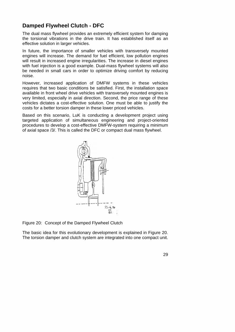
Based on this scenario, LuK is conducting a development project using targeted application of simultaneous engineering and project-oriented procedures to develop a cost-effective DMFW-system requiring a minimum of axial space /3/. This is called the DFC or compact dual mass flywheel.
Figure 20: Concept of the Damped Flywheel Clutch
The basic idea for this evolutionary development is explained in Figure 20. The torsion damper and clutch system are integrated into one compact unit.
30
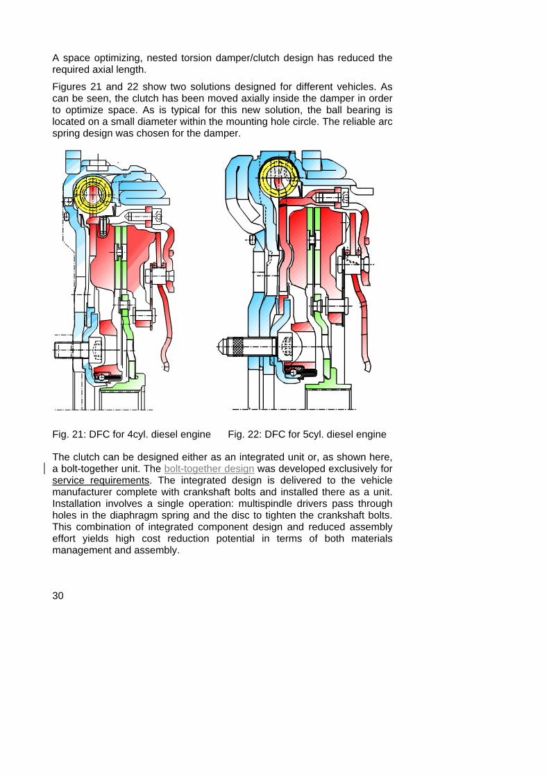
A space optimizing, nested torsion damper/clutch design has reduced the required axial length.
Figures 21 and 22 show two solutions designed for different vehicles. As can be seen, the clutch has been moved axially inside the damper in order to optimize space. As is typical for this new solution, the ball bearing is located on a small diameter within the mounting hole circle. The reliable arc spring design was chosen for the damper.
Fig. 21: DFC for 4cyl. diesel engine Fig. 22: DFC for 5cyl. diesel engine
The clutch can be designed either as an integrated unit or, as shown here, a bolt-together unit. The bolt-together design was developed exclusively for service requirements. The integrated design is delivered to the vehicle manufacturer complete with crankshaft bolts and installed there as a unit. Installation involves a single operation: multispindle drivers pass through holes in the diaphragm spring and the disc to tighten the crankshaft bolts. This combination of integrated component design and reduced assembly effort yields high cost reduction potential in terms of both materials management and assembly.
31
Both designs feature additional rings mounted on the primary side of the clutch. They are used to increase the moment of inertia of the primary side and therefore to reduce the effective torsional irregularity passed on to the crankshaft, and especially to any engine accessories. The isolation effect of the torsion damper does not require any increase in the moment of inertia on the primary side.
The additional inertial masses are manufactured from sheet steel in a cost-effective forming operation. LuK has developed special production technology in order to provide a cost-optimized and technically sound solution.
The following features represent important milestones during the development of the DFC:
• the thermal performance of the clutch system • the ball bearing • the forming operation • the seal design • the assembly process The first three points will be briefly addressed here.
The reduction in clutch diameter and the need to achieve existing performance in a more compact, integrated design make it necessary to pay special attention to the heat build-up in the system.
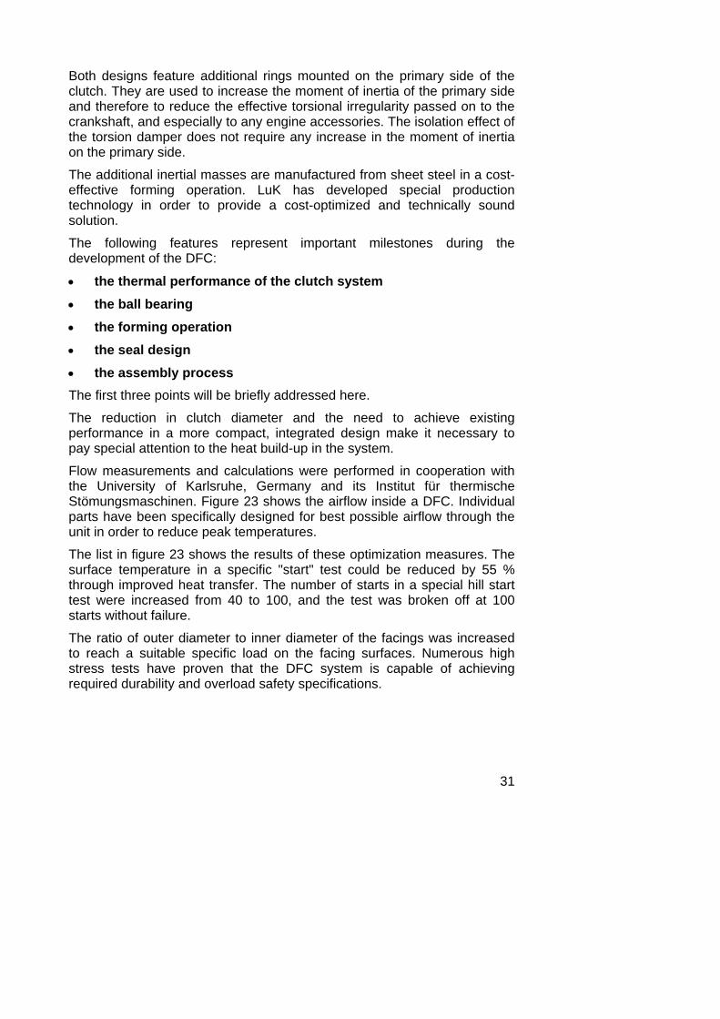
Flow measurements and calculations were performed in cooperation with the University of Karlsruhe, Germany and its Institut für thermische Stömungsmaschinen. Figure 23 shows the airflow inside a DFC. Individual parts have been specifically designed for best possible airflow through the unit in order to reduce peak temperatures.
The list in figure 23 shows the results of these optimization measures. The surface temperature in a specific "start" test could be reduced by 55 % through improved heat transfer. The number of starts in a special hill start test were increased from 40 to 100, and the test was broken off at 100 starts without failure.
The ratio of outer diameter to inner diameter of the facings was increased to reach a suitable specific load on the facing surfaces. Numerous high stress tests have proven that the DFC system is capable of achieving required durability and overload safety specifications.
32
Wm2 K[ • ]
heat transfercoefficient α
surfacetemperature ϑ
at time t[°C]
number ofstart-ups
[ - ]
low
high
177
112
45
100
1
Figure 23: Airflow distribution and thermal performance in the DFC
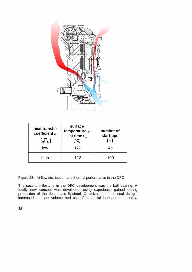
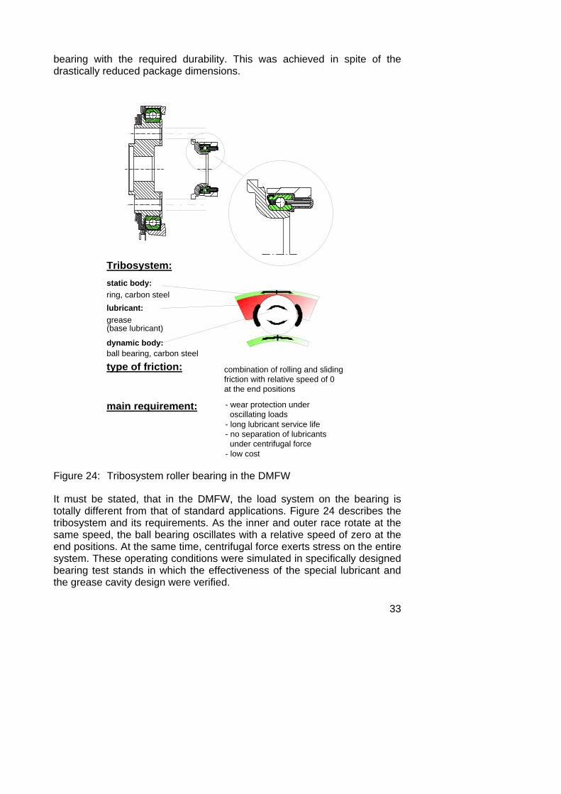
The second milestone in the DFC development was the ball bearing. A totally new concept was developed, using experience gained during production of the dual mass flywheel. Optimization of the seal design, increased lubricant volume and use of a special lubricant produced a
33
bearing with the required durability. This was achieved in spite of the drastically reduced package dimensions.
Tribosystem:static body:ring, carbon steellubricant:grease(base lubricant)
dynamic body:ball bearing, carbon steel
type of friction:
main requirement:
combination of rolling and slidingfriction with relative speed of 0at the end positions
- wear protection under oscillating loads- long lubricant service life- no separation of lubricants under centrifugal force- low cost
Figure 24: Tribosystem roller bearing in the DMFW
It must be stated, that in the DMFW, the load system on the bearing is totally different from that of standard applications. Figure 24 describes the tribosystem and its requirements. As the inner and outer race rotate at the same speed, the ball bearing oscillates with a relative speed of zero at the end positions. At the same time, centrifugal force exerts stress on the entire system. These operating conditions were simulated in specifically designed bearing test stands in which the effectiveness of the special lubricant and the grease cavity design were verified.

34
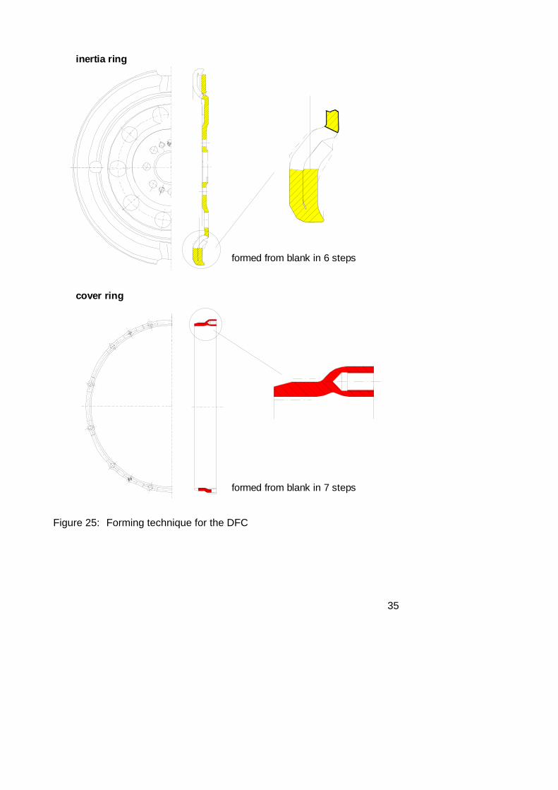
The metal forming technique used for the DFC-design was of utmost importance. Using simultaneous engineering procedures, manufacturing processes for these special plate-forming operations were developed parallel to the development of the basic system design. The goal was to ensure the most cost-effective production process for complex formed parts. Figure 25 shows two examples. The inertia ring is created using a 6-stage process whereby the outside collar on the plate blank is folded by 180 degrees.
The cover ring with a circle of blind tapped holes is also manufactured from a blank, but in seven steps. The area for the tapped hole is formed by broaching into the cover edge after the forming process. Finally the screw threads are formed during assembly, when self-tapping screws are inserted into the blind holes.
This clearly shows the intensive development required to fulfill these technical demands in a cost-effective way.
Development of the DFC will not be completed for a long time. Presently further cost-reducing solutions are being designed and tested.
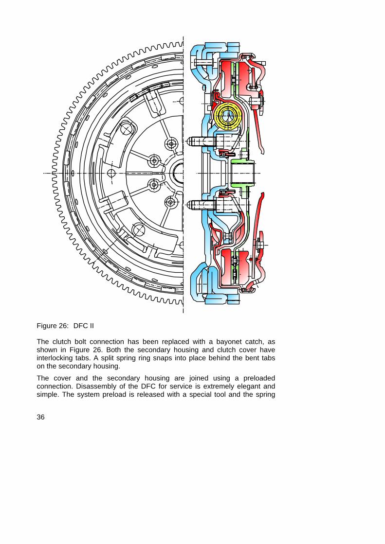
Figure 26 shows the DFC II. The basic space optimizing, nested design of the clutch and torsion damper has been maintained, but the positions of clutch and damper have been switched. The arc spring has a smaller operating diameter, but a much larger coil diameter in order to achieve sufficient damping capacity. The clutch has returned to its outer position to allow for a larger effective friction radius.
35
inertia ring
cover ring
formed from blank in 6 steps
formed from blank in 7 steps
Figure 25: Forming technique for the DFC
36
Figure 26: DFC II
The clutch bolt connection has been replaced with a bayonet catch, as shown in Figure 26. Both the secondary housing and clutch cover have interlocking tabs. A split spring ring snaps into place behind the bent tabs on the secondary housing.
The cover and the secondary housing are joined using a preloaded connection. Disassembly of the DFC for service is extremely elegant and simple. The system preload is released with a special tool and the spring
37
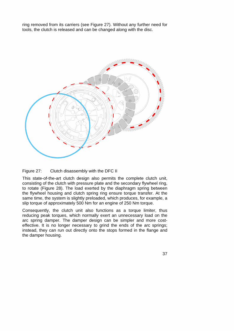
ring removed from its carriers (see Figure 27). Without any further need for tools, the clutch is released and can be changed along with the disc.
Figure 27: Clutch disassembly with the DFC II
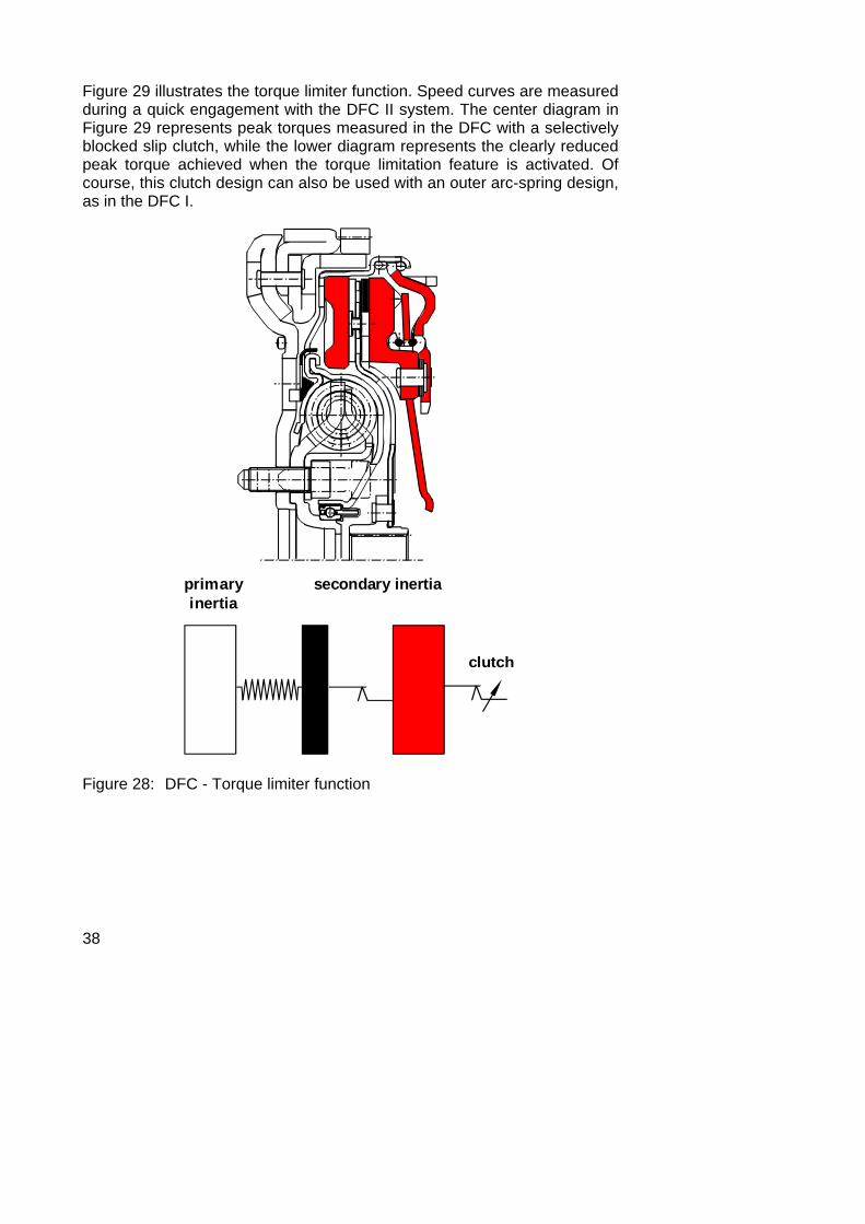
This state-of-the-art clutch design also permits the complete clutch unit, consisting of the clutch with pressure plate and the secondary flywheel ring, to rotate (Figure 28). The load exerted by the diaphragm spring between the flywheel housing and clutch spring ring ensure torque transfer. At the same time, the system is slightly preloaded, which produces, for example, a slip torque of approximately 500 Nm for an engine of 250 Nm torque.
Consequently, the clutch unit also functions as a torque limiter, thus reducing peak torques, which normally exert an unnecessary load on the arc spring damper. The damper design can be simpler and more cost-effective. It is no longer necessary to grind the ends of the arc springs; instead, they can run out directly onto the stops formed in the flange and the damper housing.
38
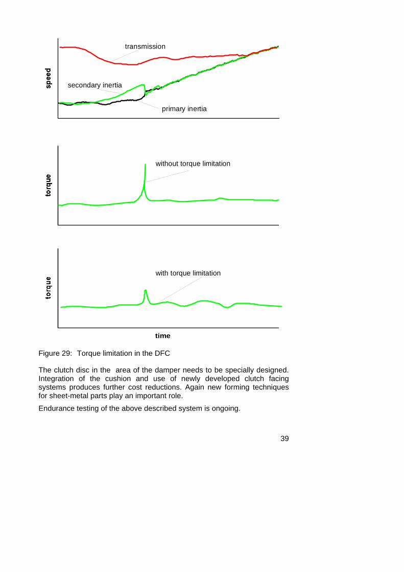
Figure 29 illustrates the torque limiter function. Speed curves are measured during a quick engagement with the DFC II system. The center diagram in Figure 29 represents peak torques measured in the DFC with a selectively blocked slip clutch, while the lower diagram represents the clearly reduced peak torque achieved when the torque limitation feature is activated. Of course, this clutch design can also be used with an outer arc-spring design, as in the DFC I.
clutch
primaryinertia
secondary inertia
Figure 28: DFC - Torque limiter function
39
time
with torque limitation
without torque limitation
secondary inertia
primary inertia
transmission
Figure 29: Torque limitation in the DFC
The clutch disc in the area of the damper needs to be specially designed. Integration of the cushion and use of newly developed clutch facing systems produces further cost reductions. Again new forming techniques for sheet-metal parts play an important role.
Endurance testing of the above described system is ongoing.
40
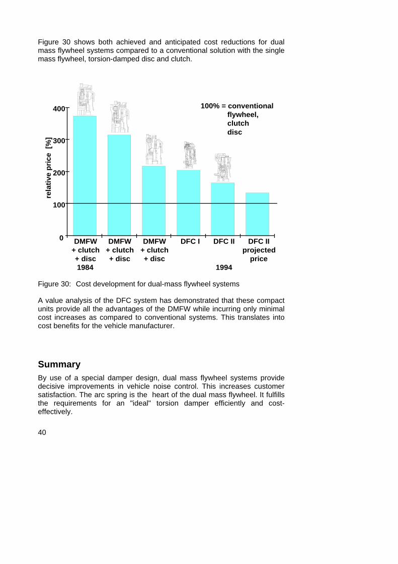
Figure 30 shows both achieved and anticipated cost reductions for dual mass flywheel systems compared to a conventional solution with the single mass flywheel, torsion-damped disc and clutch.
100% = conventional flywheel, clutch disc
rela
tive
pric
e [%
]
0
100
200
300
400
DMFW+ clutch+ disc1984
DFC I DFC II
1994
DFC IIprojected
price
DMFW+ clutch+ disc
DMFW+ clutch+ disc
Figure 30: Cost development for dual-mass flywheel systems
A value analysis of the DFC system has demonstrated that these compact units provide all the advantages of the DMFW while incurring only minimal cost increases as compared to conventional systems. This translates into cost benefits for the vehicle manufacturer.
Summary By use of a special damper design, dual mass flywheel systems provide decisive improvements in vehicle noise control. This increases customer satisfaction. The arc spring is the heart of the dual mass flywheel. It fulfills the requirements for an "ideal" torsion damper efficiently and cost-effectively.
41
Drive trains with diesel engines are controlled, without the use of idle stages, in all operating ranges. Reducing the mass connected to the crankshaft reduces the load exerted on the crankshaft and offers an opportunity for possible cost reductions in the crankshaft as well. A vehicle with a DMFW offers increased fuel economy if the following conditions are met:
• The vehicle manufacturer reduces idle speed. • The driver adopts economical driving habits by driving in higher
gears at lower engine speeds Both of these factors can be achieved without loss of driving comfort.
DFC's or the compact DMFWs offer full dual-mass flywheel function and, therefore, improved noise control for the customer; with only minimal cost increases when compared to conventional systems. The vehicle manufacturer can simultaneously reduce subassembly count and simplify vehicle assembly by selecting modular units which perform all the three main clutch system functions.
Bibliography: [1] Reik, W.; Albers, A.; Schnurr, M. u.a.:
Torque Control Isolation (TCI) The Smart Clutch. LuK-Symposium 1990.
[2] Albers, A.:
Das Zweimassenschwungrad der dritten Generation - Optimierung der Komforteigenschaften von PKW-Antriebssträngen. Antriebstechnisches Kolloquium '91, Verlag TÜV-Rheinland, 1991.
[3] Albers, A.:
Simultaneous Engineering an einem Beispiel aus der KFZ-Zulieferindustrie. Führungskräfte-Treffen '93 des VDI-EKV Verein deutscher Ingerieure, Düsseldorf 1993.
[4] Reik, W.:
Schwingungsverhalten eines PKW-Antriebsstranges mit Zweimassenschwungrad. VDI-Berichte 697, S. 173 - 194.

42