1. - defense technical information center 8. ... (15 to 29 degrees) and were damaged to near ... to...
TRANSCRIPT

1 .
ALTERNATIVE SHEAR REINFORCEMENT GUIDELINES FOR BLAST-RESISTANT DESIGN
by: Stanley C. Woodson
U.S. Army Engineer Waterways Experiment Station Vicksburg, Mississippi
William H. Gaube and Timothy C. Knight .U.S. Army Engineer District, Omaha
Omaha, Nebraska
INTRODUCTION
The use of some type of shear reinforcement is required by current manuals for the blast-resistant design of reinforced
reinforcement, normally referred to as shear reinforcement, is not to resist shear forces, but rather to improve performance in the large-deflection region by tying the two principal reinforcement mats of the slab together. Shear reinforcement used in blast-resistant design usually consists of either lacing bars or stirrups (Figure 1). Lacing bars are reinforcing bars that extend in the direction parallel to the principal reinforcement and are bent into a diagonal pattern between mats of principal reinforcement. The lacing bars enclose the transverse reinforcing bars, which are placed outside the principal reinforcement. The cost of using lacing reinforcement is considerably greater than that of using single-leg stirrups due to the more complicated fabrication and installation procedures.
D concrete slabs. The primary purpose of this type of
Two of the most commonly used manuals are the Army Technical Manuals (TM) 5-1300 (Reference 1) and 5-855-1 (Reference 2). Reference 1 is volume IV of the draft of the new TM 5-1300. A limited bank of relatively recent test data that indicate excessive conservatism in the shear reinforcement design criteria of these manuals was presented at the 23d Department of Defense Explosives Safety Seminar (Reference 3). The shear reinforcement design criteria are directly related to the allowable response limits (support rotations) of the slab. More recently, an extensive review of related test data has been conducted. Data
D
47

Report Documentation Page Form ApprovedOMB No. 0704-0188
Public reporting burden for the collection of information is estimated to average 1 hour per response, including the time for reviewing instructions, searching existing data sources, gathering andmaintaining the data needed, and completing and reviewing the collection of information. Send comments regarding this burden estimate or any other aspect of this collection of information,including suggestions for reducing this burden, to Washington Headquarters Services, Directorate for Information Operations and Reports, 1215 Jefferson Davis Highway, Suite 1204, ArlingtonVA 22202-4302. Respondents should be aware that notwithstanding any other provision of law, no person shall be subject to a penalty for failing to comply with a collection of information if itdoes not display a currently valid OMB control number.
1. REPORT DATE AUG 1990 2. REPORT TYPE
3. DATES COVERED 00-00-1990 to 00-00-1990
4. TITLE AND SUBTITLE Alternative Shear Reinforcement Guidelines for Blast-Resistant Design
5a. CONTRACT NUMBER
5b. GRANT NUMBER
5c. PROGRAM ELEMENT NUMBER
6. AUTHOR(S) 5d. PROJECT NUMBER
5e. TASK NUMBER
5f. WORK UNIT NUMBER
7. PERFORMING ORGANIZATION NAME(S) AND ADDRESS(ES) U.S. Army Engineer Waterways Experiment Station,3909 Halls Ferry Road,Vicksburg,MS,39180
8. PERFORMING ORGANIZATIONREPORT NUMBER
9. SPONSORING/MONITORING AGENCY NAME(S) AND ADDRESS(ES) 10. SPONSOR/MONITOR’S ACRONYM(S)
11. SPONSOR/MONITOR’S REPORT NUMBER(S)
12. DISTRIBUTION/AVAILABILITY STATEMENT Approved for public release; distribution unlimited
13. SUPPLEMENTARY NOTES See also ADA235005, Volume 1. Minutes of the Explosives Safety Seminar (24th) Held in St. Louis, MO on28-30 August 1990.
14. ABSTRACT
15. SUBJECT TERMS
16. SECURITY CLASSIFICATION OF: 17. LIMITATION OF ABSTRACT Same as
Report (SAR)
18. NUMBEROF PAGES
22
19a. NAME OFRESPONSIBLE PERSON
a. REPORT unclassified
b. ABSTRACT unclassified
c. THIS PAGE unclassified
Standard Form 298 (Rev. 8-98) Prescribed by ANSI Std Z39-18

2.
for 278 dynamic
tests were collected. loadinqs of reinforced
structures havinq lacinq bars
The tests consisted of static and concrete slabs and box-type stirrups, or no shear
reinforcement. Althougk this-is a 1a;ge number of tests, there remain significant gaps in the data base. A thorough study of the role of shear reinforcement (stirrups and lacing) in structures designed to resist blast loadings or undergo large deflections has never been conducted; however, as discussed in this paper the available data base is sufficient to allow a relaxation of the shear reinforcement requirements for the roof, floor, and wall slabs of some types of protective structures. Such a relaxation is evident in a recently prepared Engineer Technical Letter (Reference 4 ) applicable to protective structures designed to resist the effects of conventional weapons.
DISCUSSION OF DATA REVIEW
The data base is presented in a draft technical report (Reference 5) currently being prepared for publication at the U.S. Army Engineer Waterways Experiment Station (WES). Parameters describing construction details, testing conditions, structural response, and failure modes were tabulated and discussed. In addition to recent tests, the data base includes the tests that were conducted in the 1 9 6 0 ' s and were instrumental in the formulation of the design criteria given in the original 1969 version of TM 5-1300. As discussed in Reference 3 , the shear reinforcement design criteria have been only slightly relaxed in the new version of TM 5-1300 as compared to.the 1969 version. either laced slabs or slabs with no shear reinforcement; therefore, it is not surprising that TM 5-1300 is more restrictive €or slabs containing stirrups rather than lacing bars. collection of data available concerning shear reinforcement details in blast-resistant structures. Portions of the data base are presented in Tables 1 through 5. The reader is directed to Reference 5 for a more extensive list of tests and parameters.
A study of the data base indicates that there are several parameters in addition to shear reinforcement details that affect the large-deflection behavior of reinforced concrete slabs. These primarily include: support conditions, amount and spacing
The data developed in the 1 9 6 0 ' s primarily pertained to
The data base in Reference 5 is the most comprehensive
4 8

3 .
of principal reinforcement, scaled range, and span-to-effective- depth (L/d) ratio. The support conditions will be generalized in this discussion as either laterally restrained or laterally unrestrained. The amount of principal reinforcement will be given as the tension reinforcement ratio (p) expressed as a percentage of the width and effective depth of the slab. The scaled range (2) refers to the size and standoff of the explosive charge weight and is expressed as ft/1b1l3. parameters on slab response must be considered in the study of the role of shear reinforcement, particularly since the available data are from many separate test programs with different combinations of these parameters. An understanding of how these parameters interact to enhance the ductility of a slab will lead to the design of more economical structures.
The effects of these
Laterally Restrained Slabs
The roof, floor, and wall slabs of protective structures, particularly those in the data base, are generally laterally restrained. This is partly due to the extension of the principal reinforcement of a slab into the adjoining slab. Also, the adjacent slabs usually exhibit similar degrees of stiffness (based on thickness, span, and p ) . Lateral restraint is necessary for the formation of tension membrane forces that enhance the large-deflection behavior of slabs. The laterally- restrained boxes tested at z < 2.0 ft/lb113 were all buried and had a p of 2.0 percent. For low values of L/d in the range of approximately 6 or 7 with z = 1 . 0 ft/lb1j3, damage was slight, but support rotations (0) were low ( 5 to 7 degrees) even when no shear reinforcement was used. Generally, wall slabs of boxes having L/d values of approximately 10 to 15 experienced large support rotations ( 1 5 to 29 degrees) and were damaged to near incipient collapse. However a wall slab that had L/d = 7 and was tested at z = 0 .75 ft/lb'13 sustained a support rotation of 26 degrees without breaching, although there was no shear reinforcement. Breaching did not occur in this group of slabs until support rotations reached 1 5 degrees, and some slabs achieved support rotations significantly greater than 1 5 degrees without breaching occurring. In general, no shear reinforcement was used in this group of slabs.
D
In addition to components of the box-type structures, the data base includes slabs that were laterally restrained in test devices or reaction structures. Many of the nonlaced slabs were
49

tested in reaction devices of which the degree of lateral restraint cannot be determined with qreat confidence based on the information provided in the reports on the tests. Only two of the one-way slabs tested at z < 2.0 ft/lb"3 were definitely laterally restrained. Although one of these was lightly reinfofced (p = 0 . 1 5 ) with no shear reinforcement and with L/d approximately equal to 9 it sustained only "slight" damage when tested at z = 1 .O ft/lb'/'. rotatian or midspan deflection are not available for these slabs. Damage was described as ''heavy" when z w a s increased to 1 . 2 5 ft/lb1I3, L/d was decreased to approximately 7 , p was increased to 0 . 6 5 , and looped reinforcement (apparently, a type of stirrup €orming a rectangular loop around top and bottom bars) was used. Such variations in the data base are difficult to explain.
Unfortunately, values for support
A considerable amount of information is available for the two-way slabs that were laterally restrained with L/d greater than 2a and were tested at z = 2.0 ft/lb'13. these slabs (0.31, 1 . 0 , 1 . 5 , and 2 . 5 percent) included low, middle, and high values, considering the range of p forthe data base. For p = 1 . 0 or 1 . 5 percent, the slabs achieved support rotatims of 1 0 to 12 degrees with no failure of the tension steel and "medium" damage. Even the slab having the low value of p = 0.31 percent with no stirrups sustained a support rotation of 1 0 . 4 degrees with medium damage and no rupture of reinforcement. The support rotation was limited to 5 degrees due to the high percentage of principal reinforcement when p equalled 2 . 5 percent. The slabs that sustained large deflections did not experience breaching, although z was as low as 0 . 6 5 ft/lb1I3. When the single-leg stirrups (180-degree bends on each end) were used, they were spaced at less than one-half the thickness of the slab.
The values of p for
A review of data for the laterally-restrained laced slabs tested at z < 2.0 ft/lb1I3 provides some insight into the difference in the behavior of laced and nonlaced slabs. The fact that both a laced slab and a slab with no shear reinforcement incurred heavy damage when tested at z = 1 . 5 ft/lb'I3 and 1 . 2 5 ft/lb'13 respectively, somewhat questions the significance of lacing. When laced slabs with p = 2 . 7 percent were subjected to low z values of 0.3 and 0 . 5 ft/lb'13, they experienced heavy damage and partial destruction, respectively. It is interesting to note that a laterally-unrestrained slab with no shear reinforcement and p = 2 . 7 incurred only medium damage at
5 0

5.
z = 0.5 ft/lb1I3. of 2.7 percent overshadowed the effects of shear reinforcement on the response of these slabs.
This indicates that the effects of the large p
The data base also includes a group of laterally-restrained slabs (components of box structures) tested at z = 2.0 ft/lb1/3. The L/d values for these slabs ranged from approximately 6 to 20 and p was relatively large, 2.0 percent (the upper limit of TM 5- 855-1). Support rotations were generally small and the damage was slight (mainly hairline cracks). Support rotations were as high as 26 degrees for a wall slab of a box buried in clay. Typically, the boxes in the data base were buried in sand, which is generally known to result in less structural response than when clay backfill is used. A-slab with a L/d value of approximately 6 incurred only slight damage with a support rotation of 2 degrees when z equalled 2.0 ft/lbli3. contained single-leg stirrups, with 135-degree bends on each end, spaced at less than one-half the slab thickness. The slab that was tested in clay contained similar stirrups spaced at greater than one-half the slab thickness. As z was increased to 2.8, 4.0, and 5.0 ft/lb1I3 for some walls, support rotations remained very small (1.5, 1.0, and 2.0 degrees).
This slab
D Another type of loading called the HEST (High Explosive
Simulation Technique) was used on the roof slabs of many box structures. The HEST generally consists of a cavity covering the entire surface and containing evenly distributed strands of explosives. The cavity is covered with soil of a particular thickness to result in a desired pressure decay. Although many of the HEST tests are often considered to be “highly-impulsive,” it is likely that they may more accurately represent tests that have a charge placed at z 1 2.0 ft/lb1/3. The parameter p varied from 0.5 to 1.2 percent and the boxes usually contained single- leg stirrups with a 90-degree bend on one end and a 135-degree bend on the other end. The stirrups were spaced at less than one-half the slab thickness and the L/d values ranged from approximately 7 to 17. Generally, very little steel was ruptured in these tests. The only case in which more than 50 percent of the tension reinforcement was ruptured was for a slab with no shear reinforcement and p = 1.2 percent. A l s o , the principal reinforcement was spaced at greater than the slab thickness and the slab experienced support rotations of 15 degrees. When the principal reinforcement in a similar slab ( p = 1.1 percent) was spaced at less than the slab thickness, no steel was ruptured. This slab sustained support rotations of 14 degrees. In
B
51

6.
addition, a slab with single-leg stirrups (90- and 135-degree bends), p of only 0.51 percent (spacing less than the slab thickness), and L/d of approximately 15 achieved support rotations of 16 degrees with no rupture of steel. This group of data indicates that slabs with single-leg stirrups (90- and 135- degree bends) and L/d values from 7 to 17 are capable of sustaining support rotations up to 30 degrees with significant damage and can achieve support rotations of approximately 25 degrees with little to no rupture of steel. Actually, this was the case for some slabs that contained no shear reinforcement.
In addition to the data groups discussed above, many laterally-restrained slabs were statically loaded with uniformly distributed water pressure. In brief, these slabs achieved support rotations up to 25 degrees when no shear reinforcement was used or when single-leg stirrups (90- and 135-degree bends) were used.
Laterally-Unrestrained Slabs
Data for laterally-unrestrained, nonlaced slabs tested at z < 2.0 ft/lb113 are very limited. One of these slabs contained looped shear reinforcement, had an L/d value of approximately 7, and was tested at z = 1.0 ft/lb113. The damage was described as partial destruction. The rest of the slabs in the data base for this category contained no shear reinforcement. The damage levels ranged from slight damage to total destruction for slabs that had an L/d of approximately 10, a p of 0.15 percent, and were trested at z values from 1.7 to 1 .O ft/lb1I3. Medium damage occurred when z equalled 1.1 ft/lb113. When slabs having L/d of approximately 7 were tested at z = 0.5 ft/lb113 one with p = 0.65 percent incurred total destruction, and one with p = 2 . 7 percent incurred medium damage. Likewise, an unrestrained laced slab
2.7 percent incurred heavy damage when tested at z = 0.5 Damage was also heavy for two unrestrained laced slabs
with L/d = 7 and p = 0.65 percent when tested at z = 1.0 ft/lb113. It is obvious that unrestrained slabs with low Dercentacyes of
with ft/lb p/3= .
tension steel are susceptible to major damage when z < 5.0 f t!lb1I3.
Data for laterally-unrestrained, nonlaced slabs tested at z s 2.0 ft/lb1I3 are also very limited. an L/d of approximately 10 and a very low p of 0 . 1 5 percent. damage levels ranged from total destruction when z equalled
Four of these slabs had The
52

7 .
2.0 ft/lb113 to slight damage when z equalled 2.6 ft/lb1I3. damage also occurred when L/d was approximately 14, p equalled 0 .40 ercent, and z equalled the relatively large value of 3.5
reinforcement.
Slight
ft/lb 53 . All of these one-way slabs contained no shear
Summary
The data indicate that the response (support rotations) and the tendency for breaching of reinforced concrete slabs increase relatively quickly as z decreases below a value of 2.0 ft/lb'I3. Lateral restraint is required for large support rotations. The test procedures used in many of the tests that were conducted on one-way slabs in the 1 9 6 0 ' s and are included in the data base were not consistent with respect to support conditions. The degree of lateral restraint varied and is currently difficult to define from the available information. It is generally known that lateral restraint is inherent to two-way slabs even when support conditions are not laterally restraining.
Although there are gaps in the data base, the data do not indicate that laced slabs respond significantly different than slabs containing a similar amount of shear reinforcement in the form of single-leg stirrups. Actually, the data indicate that slabs with no shear reinforcement can sustain large support rotations in some cases due to the effects of parameters other than shear reinforcement. It appears that both laced and unlaced unrestrained slabs with low values of p are very susce tible to
D
major damage when subjected to blasts at z < 2.0 ft/lb 83 . In addition to the shear reinforcement spacing, the primary
parameters affecting the response of reinforced concrete slabs to blast loads are support conditions, amount and spacing of principal reinforcement, scaled range. and span-to-effective- depth ratio. The data indicate that combinations of some values of these parameters reduce the significance of the other important parameters, including shear reinforcement details.
APPLICATIONS
Much of the data described in Reference 5 were taken from tests on walls or roofs of buried box structures. Other above- ground tests were typically conducted using bare (uncased)
B 53

a.
explosives, which did not produce a fragment loading and consequent degradation of the slabs. A study of the data base has resulted in the development of new shear reinforcement design criteria and associated response limits (Reference 4 ) for protective structures designed to resist the effects of conventional weapons. This application of the data base reflects an improved understanding of the effects of construction parameters on slab ductility, and it results in improved economy. In brief, the criteria given in Reference 4 are presented in Table 6.
Moderate damage is described as that recommended for protection of personnel and sensitive equipment. Significant concrete scabbing and reinforcement rupture have not occurred at this level. The dust and debris environment on the protected side of the slab is moderate; however, the allowable slab motions are large. Heavy damage means that the slab is at incipient failure. Under this damage level, significant reinforcement rupture has occurred, and only concrete rubble remains suspended over much of the slab. The heavy damage level is recommended for cases in which heavy concrete scabbing can be tolerated, such as for the protection of water tanks and stored goods and other insensitive equipment.
Based on the data base, Reference 4 sets forth some design conditions that must be satisfied in order for one to use the response limits given in Table 6. The scaled range must exceed 0.5 ft/lb’I3 and L/d must exceed 5 . Principal reinforcement spacing Ps to be minimized and shall never exceed the effective depth (a). Stirrup reinforcement is required regardless of computed shear stress to provide adequate concrete confinement and principal steel support in the large-deflection region. Stirrups are required along each principal bar at a maximum spacing of one-half the effective depth (d/2) when the scaled range (z) is less than 2 ft/1b1l3 and at a maximum spacing equal to the effective depth at larger scaled ranges. are also required to resist shear, the maximum allowable spacing is d/2. 50 psi shear stress capacity. adequate lateral restraint are also given in Reference 4 but will not be g-fven in detail here.
When stirrups
All stirrup reinforcement is to provide a minimum of Some guidelines for ensuring
54

9.
The following types of stirrups are permitted in Reference 4:
a. Single-leg stirrups having a 135-degree bend at one end and at least a 90-degree bend at the other end. When 90-degree bends are used at one end, the 90-degree bend should be placed at the compression force.
b. U-shaped and multilegged stirrups with at least 135-degree bends at each end.
c. Close-looped stirrups that enclose the principal reinforcement and have at least 135-degree bends at each end.
Criteria are given in Reference 4 to account for direct shear problems. It was observed from the data base that flexible slabs that are laterally restrained are much less likely to fail in direct shear because early in the response, lateral compression membrane forces will act to increase the shear capacity, and later in the response shear forces tend to be resolved into the principal reinforcement during tension membrane action. Tests indicate that direct shear failure can occur in slabs subjected to impulsive loads. It is generally known that shear-type failure is more likely to occur in reinforced concrete members with small L/d values than it is in those with large L/d values. Since the data base indicates that laterally restrained slabs with L/d 2 8 are unlikely to experience direct shear failures, Reference 4 only requires design for direct shear for laterally restrained slabs having L/d < 8 and for all laterally unrestrained slabs. This is considered to be conservative, but the degree of conservatism is unknown due to gaps in the data base. The design procedures given in Reference 4 for direct shear design will not be presented here.
D
CONCLUSIONS AND RECOMMENDATIONS
Several parameters play key roles in enhancing the ductility of a blast resistant reinforced concrete slab. Allowable design response limits should not be based solely on shear reinforcement details and the scaled range. Although more data and study may be needed prior to the development of new design methodology and new guidelines for response limits for structures designed to resist the effects of accidental explosions, new guidelines have been developed for response limits for structures designed to
55

10 .
resist the effects of conventional weapons. For these structures the primary concern is often the completion of a wartime mission with less emphasis on the continued utiliky of the structure.
The data base does further indicate that the shear reinforce- ment design criteria in current manuals are overly conservative. In particular, the study of the data has indicated that the development of the shear reinforcement design criteria in TM 5- 1300 was based on a test program consisting primarily of laced slabs and slabs with no shear reinforcement. It is now clear that slabs that contain stirrups and are properly detailed in other aspects of construction (support conditions, L/d, p, and reinforcement spacing) are capable of performing as well as laced slabs.
Some data gaps need to be filled and perhaps proof tests need to be conducted before guidelines are developed that will result in more economical facilities used for explosives handling and storage.- A static test series for studying slabs with lacing bars, stirrups, or no shear reinforcement is planned for FY 91 . Dynamic tests are also needed, as well as further analytical effort, for evaluating such tests and developing new design guidelines.
ACKNOWLEDGMENTS
This-paper was based on work sponsored by the Headquarters, U.S. Army Corps of Engineers, and by the Department of Defense Explosives Safety Board. Helpful comments were provided by representatives of Applied Research Associates, Inc.; the U.S. Army Engineer Division, Huntsville; the Naval Civil Engineering Laboratory and the Headquarters, U.S. Army Corps of Engineers. Permission to publish this paper was granted by the Office, Chief of Engineers and is gratefully acknowledged.
56

/LACING
i I FLEXURAL REINF.
a. Lacing reinforcement
b. Stirrup configurations
57

TABLE 1. S = principal steel spacing LATERALLY-RESTRAINED U = not reported (unknown)
BOXES S, = shear reinforcement spacing t = slab thickness
1.5 1.4 0.75 1.9 ,
1.2 1.5 1.2 1 .o 1.16
UI 03
1.8 1.8 1.86 1.5 1 .o 1.9
8 8 6
12 9
10 12
6 18 12 9
18 6 5 9
29 28 26 15 10 10
7 7 2 2 1 0 0 5 2
None None None None None
None None None None None None None
None
1 35-S-135
1 35-S-1 35
z 2 2.0
2.0 1 0 26 1 35-S-1 35
2.0 10 7 1 35-S-1 35 2.0 10 6 1 35-S-1 35 2.0 10 4.5 1 35-S-1 35 2.0 10 4 1 35-S-1 35 2.0 10 3.5 1 35-S-1 35
2.3 18 10 None
Y Y Y Y Y Y Y Y Y Y Y Y Y Y Y
Local Breach U U
Local Breach Major Damage
U Major Damage
Slight Slight Slight Slight Slight Slight U
Slight
N U
N U N U N U N U N Slight
--- Local Breach
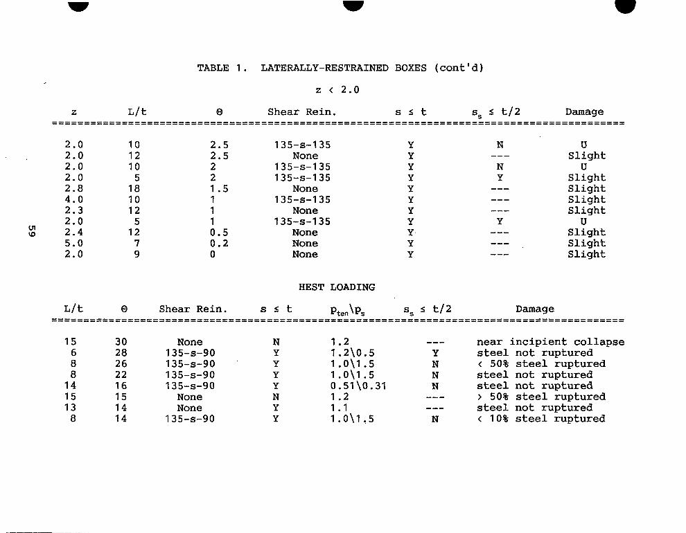
TABLE 1. LATERALLY-RESTRAINED BOXES (cont'd)
z < 2.0
2.0 2.0 2.0 2.0 2.8 4.0 2.3 2.0 2.4 5.0 2.0
10 12 10
5 18 10 12
5 12
7 9
2.5 2.5 2 2 1.5 1 1 1 0.5 0.2 0
1 35-S-1 35
1 35-S-1 35 1 35-S-1 35
1 35-S-1 35
1 35-S-1 35
None
None
None
None None None
Y Y Y Y Y Y Y Y Y Y Y
N
N Y
u Slight U
Slight Slight Slight Slight U
Slight Slight Slight
HEST LOADING
15 6 8 8
1 4 15 13
8
30 28 26 22 1 6 15 1 4 1 4
None 1 35-S-90 1 35-S-90 1 35-S-90 1 35-S-90 None None
1 35-S-90
N Y Y Y Y N Y Y
1.2 --- near incipient collapse 1.2\0.5 Y steel not ruptured 1 .0\1.5 N < 50% steel ruptured 1 .0\1.5 N steel not ruptured 0.51 \O. 31 N steel not ruptured 1.2 --- > 50% steel ruptured 1.1 --- steel not ruptured 1 .0\1.5 N < 10% steel ruptured

6 6 8 8
13 13 13 13
15 13 15 13
8 . 5
m 0
1 1 9 8 4 3 .1 2.5 2 2 1 . 5 1 .5 1 1 0 . 5
1 35-S-90 1 35-S-90 1 35-S-90
closed-hoop double-leg double-leg double-leg double-leg double-leg
None double-leg
None double-leg
Y Y Y Y N N N N Y N N N N
0 . 7 5 \ 0 . 5 1 . 2 \ 0 . 5 1 . 5 \ 1 . 5 0 . 5 \ 0 . 2 5 0 . 6 9 \ 0 . 1 8 0 . 6 9 \ 0 . 1 8 0 .69 \0 .18 0 .69 \0 .18 1 . 0 \ 1 . 5 1 . 2 0 . 6 9 \ 0 . 1 8 1 . 2 0 .69 \0 .18
steel not ruptured steel not ruptured steel not ruptured steel not ruptured steel not ruptured steel not ruptured steel not ruptured steel not ruptured steel not ruptured
< 10% steel ruptured steel not ruptured
< 10% steel ruptured steel not ruptured

SD = Slight damage MD = Medium damage
TABLE 2. NONLACED SLABS HD = Heavy damage PD = Partial destruction TD = Total damage
2 < 2.0 Laterally
z L/t Shear Rein. s s t Ptension % Restrained Damage ....................................................................................... ....................................................................................... 1.7 8 None Y 0.15 N SD 1.7 8 None Y 0.15 N SD 1.65 8 None Y 0.15 N PD 1.6 6 None N 0.65 U PD 1.5 8 None Y 0.15 U TD 1.5 1 4 None Y 0.40 U SD 1.5 14 None Y 0.40 U HD 1.25 6 None N 0.65 U TD 1.25 6 None N 0.44 U HD 1.25 6 None N 0.65 U HD 1.25 6 None N 0.65 U PD 1.25 6 Looped N 0.65 Y HD 1.1 8 None Y 0.15 N MD 1.05 8 None Y 0.15 N PD 1.02 7 None Y 0.15 U TD 1 .o 8 None Y 0.15 N TD 1 .o 8 None Y 0.15 N TD 1 .o 7 None Y 0.15 Y SD 1 .o 6 None N 0.65 U TD 1 .o 6 Looped N 0.65 N PD 0.8 6 None N 0.65 U TD 0.5 1 4 None Y 0.40 U TD 0.5 8 None Y 0.15 N TD 0.5 6 None N 0.65 U HD
o\ c-l

TABLE 2. NONLACED SLABS (cont'd)
z < 2.0 I
Laterally z L/t Shear Rein. s s t ptension % Restrained Damage
. . . . . . . . . . . . . . . . . . . . . . . . . . . . . . . . . . . . . . . . . . . . . . . . . . . . . . . . . . . . . . . . . . . . . . . . . . . . . . . . . . . . . . . . . . 0.5 6 None N 0.44 U TD 0.5 6 None N 0.65 U HD 0.5 6 None N 0.65 U TD 0.5 6 None N 0.65 N TD 0.5 4 None N 2.70 N MD 0.5 2 None N 0.15 U TD 1.1 20 None Y 0.31 Y 8 = 10.4'; no steel failed
Q\ 0.68 20 1 80-S-1 80 Y 1 .o Y 8 = 12.2'; no steel failed (MD) 0.68 20 1 80-S-1 80 Y 1 .o Y 8 = 10.1'; no steel failed (MI) 0.65 20 1 80-S-1 80 Y 1.5 Y 8 = 10.5'; no steel failed (MD) 0.65 20 1 80-S-1 80 Y 2.5 Y 0 = 4.8'; no steel
shear crack @ one support (MD)
// N
failed (SD-MD)
z 2 2.0
2.0 8 None Y 0.15 U 2.6 8 None Y 0.15 N 2.6 8 None Y 0.15 N 2.62 8 None Y 0.15 N 3.5 1 4 None Y 0.40 U
TD SD PD SD SD

TABLE 3. LACED SLABS
2 < 2.0
I .5 1.25 1 .o 1 .o 1 .o 1 .o 1 .o 0.9 QI
w 0.8 0.8 0.5 0.5 0.5 0.5 0.5 0.5 0.4 0.4 0.35 0.3 0.3
6 6 6 6 6 6 6 6 6 6 6 6 6 6 4 2 6 1.8 2 2 2
0.65 0.65 0.65 0.65 0.65 0.65 2.70 2.70 0.65 0.65 0.65 0.65 0.65 2.70 2.70 0.69 0.65 0.65 2.70 2.70 2.70
0.15 0.40 0.15 0.40 0.15 0.15 1.20 1.20 .
0.15 0.40 0.40 0.15 0.40 1.20 1.20 0.53 0.40 0.53 1.20 1.20 1.20
Y U N N Y Y Y Y N N U U U N Y U U U Y Y Y
HD MD HD HD HD PD HD HD PD MD HD PD PD HD HD MD HD HD HD HD PD

TABLE 4. NONLACED SLABS STATICALLY-LOADED
11.2 12.6 13 1 4 1 4 1 4 1 4 14.5 14.5
QI 15 15.5 1 6 16.5 16.5 16.5 16.7 17 17 18 1 8 18 1 8 18.8 19.5 19.5 19.7 19.7
P
15 10 10 10 10 10 10 10 15 15 10 15 10 10 10 15 10 15 10 15 10 10 10 10 10 10 10
1 35-S-90 1 35-S-90 1 35-S-1 35
1 35-S-1 35 1 35-S-90
double-leg
None 1 35-S-1 35 1 35-S-90 1 35-S-90 1 35-S-1 35 1 35-S-90 1 35-S-90
1 35-S-1 35 1 35-S-90 1 35-S-90 1 35-S-90 1 35-S-90 1 35-S-90 1 35-S-1 35
1 35-S-90 1 35-S-90 1 35-S-90
None
None
None None
N N N N N N N N N N N N N N N N N N N N N N N N N N N N Y N N N N N N N N N N N Y Y N N N N N Y N N N N N N
1.14/0.18 0.74/0.18 0.74/0.09 0.74/0.19 0.74/0.18 0.74/0.18 1.58 0.74/0.18 1.47/0.24 1 .47 /0 .24 0.74/0.18 0.58/0.18 1.06/0.27 0.74 0.75/0.19 1.14/0.18 0.52/0.22 0.58/0.18 0.74/0.18 1.14/0.18 0.75/0.38 0.74 0.74/0.18 1 .13 /0 .22 0.52/0.22 0.79 1.13
> 50% tension steel ruptured < 50% tension steel ruptured > 50% tension steel ruptured > 50% tension steel ruptured > 50% tension steel ruptured > 50% tension steel ruptured No steel ruptured > 50% tension steel ruptured No steel ruptured No steel ruptured > 50% tension steel ruptured > 50% tension steel ruptured < 50% tension steel ruptured > 50% tension steel ruptured > 50% tension steel ruptured No steel ruptured > 50% tension steel ruptured > 50% tension steel ruptured < 50% tension steel ruptured No steel ruptured > 50% tension steel ruptured > 50% tension steel ruptured > 50% tension steel ruptured > 50% tension steel ruptured > 50% tension steel ruptured > 50% tension steel ruptured < 50% tension steel ruptured

TABLE 4. NONLACED SLABS STATICALLY-LOADED (cont'd)
20 10 20.5 10 20.5 10 21 10 22.5 10 22.5 8.4 23.5 10 23.5 10 23.5 10 24 10 24.5 10
0 u1
1 35-S-90 1 35-S-1 35 None None None 1 35-S-90 1 35-S-90
1 35-S-1 35
1 35-S-90
None
None
N N N N N Y N N N N N
N Y N N N N Y N N N Y
0.74/0.18 > 50% tension steel ruptured 0.74/0.36 > 50% tension steel ruptured 1.14 < 50% tension steel ruptured 1.14 > 50% tension steel ruptured 1.13 < 50% tension steel ruptured 1.02/1.53 > 50% tension steel ruptured 1.13/0.22 > 50% tension steel ruptured 1 .I4 > 50% tension steel ruptured 1.13/0.06 > 50% tension steel ruptured 0.79 > 50% tension steel ruptured 1.13/0.22 > 50% tension steel ruptured

TABLE 5 . LACED SLABS STATICALLY LOADED
8 . 5 24 0 . 8 2 / 0 . 1 9 N Y
9 . 2 24 2 . 1 1 / 1 . 3 7 Y Y 1 1 24 0 . 8 9 / 0 . 4 2 N Y
12 .5 24 0 . 8 2 / 0 . 1 9 N Y
1 3 . 2 24 0 . 8 2 / 0 . 1 9 N Y
Y steel condition not
Y no steel ruptured Y steel condition not
Y steel condition not
Y steel condition not
reported
reported
reported
reported

Table 6. Design Criteria from Reference 4
Lateral Restraint Damage Response Limit Condition Level (Degrees ) .......................................................
6 Unrestrained ------ Restrained Moderate 12 Restrained Heavy 20
67

1 1 .
- REFERENCES ~-
1. M. Dede and N. Dobbs, "Structures to Resist the Effects of Accidental Explosions, Volume IV, Reinforced Concrete Design," Special Eublication ARL-SP-84001, U . S . Army Armament Research Development and Engineering Center, Picatinny Arsenal, New Jersey, Kpril 1987.
2. Department of the Army, "Fundamentals of Protective Design for Conventional Weapons," TM 5-855-1, U.S. Government Printing Office, Washington, D.C., November 1986.
3 . S. A. Kiger, S. C. Woodson, and F. D. Dallriva, "Shear Reinforcement in Blast Resistant Design," Minutes of the Twenty- Third Department of Defense Explosives Safety Seminar, Department of Defense Explosives Safety Board, Washington, D.C., August 1988.
4 . Department of the Army, "Response Limits and Shear Design for Conventional Weapons Resistant Slabs," Engineer Technical Letter (being prepared for printing), U.S. Government Printing Office, Washington, D.C., July 1990.
5. S. C. Woodson, "Response Limits of Blast-Resistant Slabs," Draft Technical Report, U.S. Army Engineer Waterways Experiment Station, Vicksburg, Mississippi, 1990.
4 68