1 control of a small wind turbine in the high wind speed
TRANSCRIPT

1
Control of a Small Wind Turbine in the High WindSpeed Region
Carlos Lumbreras, Student Member, IEEE, Juan M. Guerrero∗, Member, IEEE, Pablo Garcıa,Member, IEEE, Fernando Briz, Senior Member, IEEE, and David Reigosa, Member, IEEE,
Electrical and Computer Engineering Department - University of OviedoCampus de Viesques Ed. Dept. Oeste n2, 33204 Gijon (Spain)
Tel: +34-985 18 25 31 e-mail: ∗[email protected]
Abstract—This paper proposes a new soft-stalling controlstrategy for grid-connected small wind turbines operating inthe high and very high wind speed conditions. The proposedmethod is driven by the the rated current/torque limits of theelectrical machine and/or the power converter, instead of therated power of the connected load, which is the limiting factorin other methods. The developed strategy additionally deals withthe problem of system startup preventing the generator fromaccelerating to an uncontrollable operating point under a highwind speed situation. This is accomplished using only voltageand current sensors, not being required direct measurements ofthe wind speed nor the generator speed. The proposed method isapplied to a small wind turbine system consisting of a permanentmagnet synchronous generator and a simple power convertertopology. Simulation and experimental results are included todemonstrate the performance of the proposed method. Thepaper also shows the limitations of using the stator back-emfto estimate the rotor speed in permanent magnet synchronousgenerators connected to a rectifier, due to significant d-axiscurrent at high load.
I. INTRODUCTION
Renewable energy generation and integration are impor-tant topics not only from an electrical engineer perspectivebut also from a social perspective, due to environmental,economic and strategic reasons. For small consumers, theinterest in energy self-production is growing due to the riseof the electricity price, specially in countries without gasand oil production. One of the more affordable and efficienttechnologies to produce electricity for residential or smallbusiness consumers are small wind turbines [1]–[3].
Small wind turbine systems can inject the energy directlyinto the grid [4]–[13] or store the captured energy in batteries[14]–[20]. The system presented in this paper is intended forgrid-tied operation. Different power converter topologies havebeen proposed for the case of grid-tied applications [21]–[24].The most widely used converter topology on the generatorside for low-power grid-tied systems consists of a dioderectifier and a boost converter [5]–[11], [25]. Alternatively aboost rectifier has also been proposed [26]. An active rectifierwith only three active switches was proposed in [19]. Tointerface the generating system with the grid, either an H-bridge inverter [4]–[7] or three phase phase inverter [9]–[11] can be used. With the aim of reducing the number ofpower components in the passive rectifier plus boost converterplus H-bridge configuration, a special back-to-back inverterwas proposed in [27]. However, that solution implies a morecomplex control and the need of a shaft position sensor. Toavoid the use of a shaft position sensor using such topology,a sensorless controller was developed in [13]. The simplest
topology based on the passive rectifier, boost rectifier andH-bridge converter is used in the present study.
One of the challenges in the operation of small windturbines is the control and protection under high wind speeds.Whenever the wind power exceeds the turbine power rating,the turbine must be operated below its maximum efficiencypoint to prevent damage. Some braking mechanism mustbe enabled if the wind power excess is too high. Pitchcontrol, furling control, stall control, mechanical brakes andelectric brakes have been proposed for this purpose [16], [28].The electric brake using a crowbar to shortcut the generatorwindings to produce a high braking torque is the preferredoption for small wind turbines, due to its simplicity andreduced cost. However, this method has some drawbacks,including a high torsional torque in the turbine shaft andlarge currents in the generator windings, which can eventuallydamage the system. To avoid the activation of the crowbaror the use of more complex methods, soft-stall control wasproposed for small wind turbines [8], [14], [20], [25], [29]to limit the extracted power to the demanded power by theload. Soft-stall methods operate the turbine at a non-optimaltip speed ratio (TSR) to decrease the power extracted fromthe wind.
The proposed soft-stall methods [8], [14], [20], [25], [29]consider that a high wind speed condition is produced whenthere is a mismatch between the maximum wind power thatcan be extracted with the turbine and the load demand.Therefore, the TSR is reduced to make the extracted powerequal to the load power. Those methods assume that the gen-erator drive (i.e. generator and power converter) can alwaysproduce a torque to counteract the torque produced by thewind turbine. Nevertheless, in grid connected applications,assuming a strong grid, the maximum power that can beextracted will only be imposed by the rated power of thegenerating system. In this case, the relevant variable thatmust be kept under control in terms of high wind speedprotection is the turbine torque rather than the turbine power.A high wind speed is here considered that producing sometorque above the rated value of the generator drive withinthe operating generator speed range. This paper proposes asoft-stall method to maintain the turbine generating duringhigh wind speed conditions without connecting the crowbar.
In some situations, the torque exerted by the wind turbinewill surpass the maximum value of the generator drive, andthe crowbar (or a mechanical brake) will be unavoidableactivated to stop the turbine. Once the turbine is stopped,a strategy for its restart is needed. This is not obvious,as low cost systems do not include wind speed sensors.Commercial micro-turbines often wait a short period of time

2
Windturbine
PM
GeneratorGrid
vr vdc
Boostconverter
ib
Linefilter
ig vg
H-bridgeinverterRectifier
ibvr
vr*generator
vr*
vr
-
+PI PI
ib* vl*
ib-
+PWM
gB
gB
gTLgTRgBLgBR
gTL gTR
gBL gBR
PI_NotchPLL
PRvdc*
vdc
-
+
ig* vlf*
ig-
+
vg
igRMS*
PWM
a)
b) c)
Fig. 1. Schematic representation of the wind energy generation system: a) Wind turbine, generator and power converter; b) Block diagram of the boostconverter control system; c) Block diagram of the H-bridge converter control system.
before restarting whenever the electrical brake is activated. Ifthe wind speed remains too high, the wind turbine starts andstops repeatedly, which stresses and can eventually damagethe system in the long term. On the contrary, disconnectingthe wind turbine longer than needed obviously has a negativeeconomic impact. The proposed method allows automaticreconnection by maintaining the turbine operating at lowspeed while the wind speed remains high. This reducesboth the mechanical and electrical stress over the generatingsystem and additionally increases the energy harvested fromthe wind. However, the economic improvement of the latterwill be ultimately dictated by the number of high wind speedevents along the year and the electricity price.
The developed method has two unique and distinctivecharacteristics: 1) It is driven by the rated current/torquelimits of the electrical machine and/or the power converter,instead of the rated power of the connected load; 2) It dealswith the problem of system startup during a high wind speedsituation. The method uses only current and voltage sensorswhich are typically available in low-cost microwind turbines,being therefore a cost-effective solution. The method has beensimulated and implemented on a 2.5 kW wind generator sys-tem, consisting of a permanent magnet synchronous generator(PMSG) , a diode rectifier, a boost DC/DC converter and aH-bridge inverter for single-phase grid connection. It is notedhowever that the proposed concept is also applicable to othermachine designs and power converter topologies.
II. SYSTEM DESCRIPTION
Fig. 1 shows a schematic representation of the system. Itconsists of a wind turbine directly coupled to a three-phasePMSG and an integrated power converter. The hardwarecomponents seen in Fig. 1a are described in this section,while the control loops shown in Fig. 1b-c will be describedin sections III and IV.
A. Wind turbineA fixed-pitch wind turbine has been used in the present
study. Table I summarizes some characteristic turbine param-eters. The power extracted by a wind turbine depends on thewind speed, the constructive parameters of the turbine, andthe rotor speed (1),
P =1
2ρARcp(λ, ϑ) v3
w (1)
TABLE I. TURBINE PARAMETERS
Rated power output 1.2 kWRated wind speed 12 m/sRated rotor speed 600 rpmTurbine radius, R 0.875 mTurbine inertia constant 0.74 kg · m2
Optimal TSR, λmax 4.6Optimal power coeffcient, cp max 0.47
0 2 4 6 8 10 12 140
0.1
0.2
0.3
0.4
0.5
Tip speed ratio (λ)
Pow
ercoeffi
cient(C
p)
λmax
cp max
Fig. 2. Power coefficient of the wind turbine as a function of the tip speedratio.
where P is the extracted power, ρ is the air density, AR is theswept area, R is the turbine radius, cp the power coefficient,λ = (ωrmR)/vw the tip speed ratio (TSR), ϑ the bladespitch angle, ωrm the rotor mechanical speed, and vw the windspeed.
However, the power coefficient depends only on the tipspeed ratio in fixed-pitch turbines. This power coefficient canbe approximated by a nonlinear function whose parameterscan be estimated from experimental data [30]. Steady-statepower vs. rotor speed experimental data provided by the tur-bine manufacturer, including wind speeds up to 26 m/s, havebeen used in the present study to obtain the power coefficientcurve seen in Fig. 2, where cp max is the maximum powercoefficient obtained with the optimal tip speed ratio λmax.
The curve seen in Fig. 2 has been used both in simula-tions and in the wind turbine emulator to obtain the power

3
TABLE II. PMSG PARAMETERS
Rated power 2.5 kWRated current 3.7 AMaximum current 10 ARated voltage 400 VRated speed 700 rpmPole number 12Magnets’ voltage constant Ke 1.188 Vpk/rpmStator resistance Rs 6.03 ΩStator inductance Ls 0.063 HRotor inertia constant 0.00581 kg · m2
and torque exerted by the turbine at different wind speeds,including high wind speeds. The model presents the followinglimitations:• The effect of passive stall over the turbine blades at
high wind speed is not considered. This provides aworst case scenario to the present study from the pointof view of high wind speed protection, since the actualtorque at high wind speeds would be smaller than thepredicted by the model.
• Dynamic stall effects are not included in the model.Therefore, the torque variations due to excursionsfrom the static power coefficient when the wind speedchanges can be seen as disturbances for the proposedcontrol system.
• Considerations about the possible mechanical stresses,vibrations, and system mechanical or structural failureare not covered in this paper. The study is focused inthe protection of the electrical subsystem.
B. Permanent magnet synchronous generator (PMSG) andrectifier
A PMSG whose parameters are shown in Table II isused to perform the electro-mechanical conversion. It isdirectly coupled to the wind turbine shaft without a gearbox.The machine produces a three-phase voltage, E, at no loadwhose magnitude and frequency change proportionally to therotor speed of the machine (2), with Ke being the back-electromotive force constant and ωr the rotor speed.
E = Keωr (2)
When the machine is loaded, the output voltage decreasesdue to the stator impedance, the model given by (3) is oftenused, where ωr is the rotor speed, Vgen is the phase-to-phaserms voltage and Ig is the rms phase current. This model isthen combined with the rectifier model to obtain the rectifiervoltage and to map the power-speed curves to power-voltageones [5], [8], [20].
Vgen = E − Ig(Rs + jωrLs) (3)
However, that model is not accurate since the current vectoris not necessary orthogonal to the back-emf voltage vectorof the machine when a passive rectifier is used, mainly dueto the presence of the input capacitor. Therefore, some d-axis current is produced, weakening the machine flux anddecreasing the back-emf. That makes the voltage seen by therectifier smaller than the value provided by (3). Obtaininganalytical expressions for this voltage drop is not straight-forward. This problem was overcome by characterizing thecombined behavior of the PMSG and the rectifier by means ofnumerical simulation. Several rotor speeds and current levelswere imposed to the PMSG and the corresponding rectifier
0 100 200 300 400 500 600 700 800 900
0
200
400
600
800
1000
Mechanical speed ωrm (rpm)
Average
rectified
voltagevr(V
)
vw = 5 m/svw = 14.8 m/svw = 21 m/svw = 32 m/s
Fig. 3. Average output rectifier voltage (vr) vs. generator speed (ωrm)when this speed is sustained by the generator for different wind speeds.
0 100 200 300 400 500 600 700 800 9000
500
1000
1500
2000
2500
Mechanical speed, ωrm (rpm)
Mechan
ical,P,an
delectrical
pow
erPe(W
)
vw =5m/svw =7m/s
vw =9m/s
vw =11m/s
vw =13m/s
vw =15m/s
Fig. 4. Turbine (blue) and generator (red) power as a function of the turbinerotor speed (ωrm) and wind speed (vw).
output voltage and the exerted torque were obtained. Thesimulations showed a significant d-axis component of thestator current vector when the boost current increases. Fig. 3shows the relationship between the generator speed and therectifier voltage when the boost current needed to match thetorque produced by the turbine at different wind speeds isdrawn from the generator. It is clearly seen in Fig. 3 that thevoltage drop of the stator voltage cannot be only explainedby the stator impedance due to the nonlinear behavior of thevoltage drop as the wind speed (i.e. current level) increases.
Fig. 4 shows the steady-state power versus rotor speedcurves of the turbine for different wind speeds. The electricalpower that can be extracted from the rectifier is inferior tothe mechanical power due to the generator losses, as can beseen in Fig. 4. This produces a displacement of the actualmaximum power point trajectory (MPPT).
Since the mechanical speed is not measured, the electricalpower versus the rectifier voltage curves can be used insteadfor MPPT, as can be seen in Fig. 5. The dotted line shows theactual MPPT, while the segmented line is the approximatedMPPT used by the MPPT controller. The cut-in wind speedis set to 5 m/s corresponding to a rectifier voltage of 280 V,termed VR MIN . VR MAX is the maximum rectifier outputvoltage the system can withstand. This limit is imposed by therated voltage of the input capacitors and the power devices.

4
0 200 400 600 8000
500
1000
1500
2000
2500
Average output rectifier voltage, vr (V)
Electricalpow
er(W
)
vw =5m/s
vw =7m/s
vw =9m/s
vw =11m/s
vw =13m/s
vw =15m/s
VR MAXVR MIN
Fig. 5. Electrical power versus rectifier output voltage curves for differentwind speeds showing the maximum power point trajectory (dotted line), andthe approximated trajectory used for control (straight line segments).
TABLE III. BOOST CONVERTER PARAMETERS
Input capacitance 62.5 µFOutput capacitance 235 µFBoost inductor inductance 5 mHBoost inductor resistance 1 Ω
Beyond that voltage the system cannot follow the MPPT.In order to implement and effective turbine protection,
the current/torque versus rectifier voltage curves must becarefully analyzed. Fig. 6 shows the current required toproduce a generator torque counteracting the turbine torque,in terms of the rectifier voltage for different wind speeds.It is observed in Fig. 6 that the maximum wind speed thatcan be serviced by the system without exceeding the ratedcurrent, IB RATED (3.7 A), is 14.8 m/s. The turbine torqueproduced by a wind speed of 21 m/s can be withstood bythe generator by transitory exceeding the rated current toreach the maximum admissible level, IB MAX (i.e. 10 A inour system). This limit will depend on the transient overloadcapacity of the PMSG and of the power electronics and mustbe selected during the hardware design. Above that windspeed, the turbine can only be controlled at a relatively lowrotor speed/rectifier voltage. At the cut-in voltage VR MIN
(280 V) the generator can withstand sustained wind speedsup to 32 m/s by delivering the rated current. If the voltageis reduced to VR SAFE , sustained wind speeds of up to35.3 m/s can be withstood by the electrical system andkeep it generating. Above that level, hurricane wind speedswould require the use of external brake systems (automaticor manual) since they imply sustained torque solicitationsbeyond the rated torque of the generator. It is again remarkedthat mechanical or structural failure considerations have notbeen made in this study.
C. Power converters and sensorsThe power converter topologies used in this paper have
been shown in Fig. 1. The three-phase diode rectifier convertsthe three-phase voltage supplied by the generator into a DCvoltage, vr. A boost DC/DC converter is then used to obtaina DC voltage, vdc, larger than the rectified grid voltage. Theparameters of the boost converter can be found in table III.An H-bridge inverter is used to inject current, ig , into the
0 400 600 8000
2
4
6
8
10
Average rectifier voltage, vr (V)
Boost
currenti b,(A
)
vw =14.8 m/s
vw =21 m/s
vw = 35.3 m/s
vw = 32 m/s
VR MAXVR MINVR SAF E
IB RATED
IB MAX
ilimit
Fig. 6. Current needed to produce the torque to hold the turbine versusrectifier voltage curves for different key wind speeds. Black line showsilimit values used in over-speed protection.
grid. In order to connect the inverter output with the grid,an inductive line filter is included. This is the most usedtopology in low-cost grid-tied wind turbines [22]–[24].
A reduced set of variables are measured to control thepower converter, as can be seen in Fig. 1. These includethe rectifier voltage vr, the DC-link voltage vdc the gridvoltage vg , the boost inductor current ib and the grid currentig . Voltages are measured using resistor based sensors whileHall-effect sensors are used to measure the currents.
III. POWER CONVERTER CONTROL
Two independent control loops are used to control boththe boost converter and the H-bridge inverter, as can be seenin Fig. 1b-c. This section describes the different controllersused and their main control design goals. However, a detaileddescription about the tuning procedure and the subsystemmodels is beyond the scope of this paper.
A. Boost converter control
The wind turbine speed is controlled by the boost DC/DCconverter, which demands the current needed to create therequired braking torque in the PMSG. The speed of theturbine is indirectly controlled by imposing a rectifier outputvoltage, vr, according to the characterization described insection II-B. The command for the rectifier output voltage,v∗r , comes from a block that has been called “v∗r generator”,as can be seen in Fig. 1b, which includes both MPPT andover-speed protection algorithms, as it will be described insection IV.
The rectifier output voltage is controlled using a cascaded-control, in which the outer loop controls the rectifier outputvoltage, vr, by commanding a boost current command, i∗b ,to the inner loop controlling the boost converter current. Theoutput of the current controller is the voltage to be imposed tothe boost converter inductance, v∗l , which is translated into aduty command, gB , by a PWM generator block. Conventionalproportional-integral (PI) controllers (4) are used in bothcontrol loops.
PI(s) = kp +kis
(4)

5
where kp is the proportional gain, ki is the integral gain, ands the Laplace operator. It is noted that the gains differ foreach controller.
The sign in the rectifier output voltage error calculation inFig. 1b is reversed since to increase the rectifier voltage theboost current must be decreased. The boost current controllerhas been tuned to achieve a 500 Hz bandwidth with noovershoot in the step response. The rectifier output voltagecontroller has been tuned to achieve a bandwidth of only 0.1Hz with a maximum admissible overshoot of 5% in the stepresponse. The reason for selecting such a low bandwidth isto approximate the rectifier output voltage dynamics to theturbine/generator speed dynamics.
B. H-bridge converter control
In order to inject into the grid the same amount of energythat is being extracted from the wind, a power balance isperformed in the system trough the DC-link voltage. TheDC-link voltage, vdc, is set to a fixed reference value, v∗dc,that can only be kept constant by injecting the appropriateamount of current to the grid, ig . The DC-link voltage iscontrolled with a PI controller augmented with a notch filter(5), as can be seen in Fig. 1c.
PI Notch(s) =
(kp +
kis
)s2 + 2ξzωns+ ω2
n
s2 + 2ξpωns+ ω2n
(5)
where kp is the proportional gain, and ki is the integral gain,ξz and ξp are the damping coefficients of the notch filter zerosand poles respectively, and ωn is the central frequency of thefilter. It is noted that the controller gains are different to thePI controllers already described.
The notch filter is used to prevent the controller fromrejecting the necessary DC voltage oscillation required toabsorb the instantaneous power difference between a three-phase system, the PMSG, and a single-phase grid connec-tion. Otherwise this oscillation would be translated to thecontroller output which is the rms grid current command,i∗gRMS
. The controller has been tuned to achieve a closed-loop bandwidth of 40 Hz with the notch filter providing -20dB of attenuation at 100 Hz (i.e. single-phase instantaneouspower pulsation).
In order to achieve unity power factor, the rms grid currentcommand, i∗gRMS
, is synchronized with the grid voltageusing a synchronous phase-locked loop (PLL) algorithm [31],shown in Fig. 1c. The instantaneous grid current command,i∗g , is injected into the grid by means of the H-bridge inverter,controlled by a proportional-resonant (PR) controller (6).
PR(s) = kp + kr2 · ωr · ss2 + ω2
r
(6)
where kp and kr are the proportional and resonant gains re-spectively, and ωr is the resonant frequency. The proportionalgain has a different value than the controllers previouslydescribed.
This type of controller ensures zero tracking error at theresonant frequency which is set to the grid frequency. Thecontroller has been tuned to achieve a closed-loop bandwidthof 500 Hz, a worst case disturbance rejection frequencyresponse of -30 dB, and a resonant frequency of 50 Hz.
LPF Over-currentdetector
vr_minGenerator
MPPTTracker
ilimitLUT
MPPTLUT
LPF
ib
ib
overcurrent_flag
ilimit
vr_min
Δvimppt
ib
ib
vr
vr
vr*
vrvr
~
~ ~
~
~~
**
*
+
+
Fig. 7. Voltage reference, v∗r , generator for MPPT and over-speedprotection.
IV. OVER-SPEED CONTROL INTEGRATION
High rotor speed in the wind turbine can be harmful,as both the turbine and the electronic components can bedamaged or destroyed due to mechanical failure or excessivehigh back-emf voltages. A very high wind speed may producea torque that could not be counteracted by the generator,eventually resulting in an excessive rotor speed. Some typeof protection against high wind speeds is therefore mandatory.
A method to allow the wind turbine to operate safely withhigh wind speed is proposed in this section. The protectionis integrated along with the MPPT control. It is assumed thatneither wind speed sensor nor shaft speed sensor are avail-able. The rectifier output voltage will be used to indirectlycontrol the turbine speed according to the curves shown insection II-B.
The block diagram of the proposed protection scheme canbe seen in Fig. 7, corresponding with the block “v∗r mingenerator” seen in Fig. 1b. This system will provide a rectifiervoltage reference, v∗r , for the rectifier output voltage PIcontroller, shown in Fig. 1b. The rectifier voltage referenceconsists of a constant voltage reference, v∗r min and a variablevoltage reference, ∆v∗, tracking the maximum power point.Those two commands will be generated by the blocks labeledas “v∗r min generator” and “MPPT Tracker” in Fig. 7. Theoperation of each block in Fig. 7 is explained following:
A. Low-pass filtersThe rectifier output voltage, vr, and the boost current, ib,
contain a significant amount of ripple due to the switchingof the rectifier and of the boost converter. The informationcontained in the look-up tables that will be described inthe following sections is based on average values of bothmagnitudes. Therefore, lows-pass filtering is applied to bothsignals to obtain vr and ib respectively. The filters, shown ifFig. 7, are first order low-pass filters (LPF) (7).
LPF (s) =ωco
s+ ωco(7)
where ωco is the cutoff frequency of the filter in rad/s.The cutoff frequency of the rectifier output voltage filter
has been set to 2 Hz, while the the boost current filter hasbeen tuned to 100 Hz.
B. Maximum power point trajectory look-up tableThe MPPT look-up table (LUT) contains an approximation
of the actual MPPT of the generating system. Fig. 5 showsthe actual MPPT (dotted line) and the approximation used

6
START ofOver-current Detector
END ofOver-current Detector
ib < IB_RATED
over-current timer < 0
over-current timer > MAX
Decreaseover-current timer
Increaseover-current timer
over-current timer = 0over-current flag = 0
over-current timer = MAXover-current flag = 1
YES
YES
YES
NO
NONO
~
Fig. 8. Over-current detector flow chart.
(straight line segments). This simplification does not intro-duce meaningful losses in the harvested power in the systemunder study. If required, a more detailed LUT can be easilygenerated.
The input for the MPPT LUT block is the filtered rectifieroutput voltage, vr, and the output is the corresponding MPPTcurrent reference, imppt, instead of the corresponding powermagnitude. This current reference is simply obtained bydividing the power obtained from the approximated MPPTline between the filtered rectifier output voltage.
C. Current limit look-up tableThe “ilimit LUT” block in Fig. 7 provides a current
reference to early detect if the wind turbine can surpass therated torque of the generator at some rotor speed due to theactual wind speed. This reference has been set to approximatethe current curve for a wind speed of 14.8 m/s in the MPPTregion, as can be seen in Fig. 6, since the torque produced bythis wind speed can be serviced by the generator at all rotorspeeds. If the current delivered by the generator is higher thanthis limit at some rotor speed at steady-state this will indicatea wind speed higher than 14.8 m/s. Below VR MIN , the ilimithas been set to a higher value to allow wind speeds up to21 m/s accelerate the turbine to VR MIN . It must be pointedout that this value is imprecise since during acceleration anddeceleration the current delivered must differ for the samewind speed, and it is only used to detect relatively high windspeeds.
D. Over-current detectorThe “over-current detector” block is an up/down counter
that increases whenever the current is larger than the ratedvalue, and decreases if it is smaller. If the counter reachesa pre-established threshold, an over-current flag is set and itwill only be reset when the counter returns back to zero. Thecount up and count down steps can be unevenly selected; in
START ofvr_min generator
vr < VR_SAFE
END OFvr_min GENERATOR
vr increasing
vr << VR_SAFE
over-current flag == 1
vr << VR_MIN
& ib < ilimit
vr increasing
vr_min = vr
Limit toVR_MIN
Limit toVR_SAFE
Increasevr_min
Increasevr_min
Decreasevr_min
NO
NO
NO
NO
NO
NO
NO
YES
YESYES
YES
YES
YES
YES
~
~
~
~~
~
~~
vr_min > VR_SAFE& ib > ilimit
~
a
b
c
d
e
f
g
h
i
j
l
n
m
kvr_min
= vr
*
*
*
*
*
*
*
*
Fig. 9. Flow chart of the minimum voltage reference generator.
the implemented algorithm the count down was set to be fourtimes faster than the count up. The threshold at which the flagis set on is selected in this study by measuring the transienttime needed to bring down the voltage from VR MAX toVR MIN when the turbine is driven by a wind speed of 21m/s, which is the maximum wind speed that can be brakedat any rotor speed by temporary surpassing the rated current.The detailed flow chart of this block can be seen in Fig. 8.
E. Minimum rectifier output voltage reference generator
The “v∗r min generator” block will provide a rectifier volt-age ramp command from zero to VR MIN , where the systemstarts tracking the MPPT. The idea behind this referencegenerator is to have control over the turbine speed/voltage assoon as it starts to rotate, not leaving the turbine to accelerateuncontrolled towards the cut-in voltage, VR MIN . This isnecessary to prevent a high wind speed from building up anexcessive turbine torque at that voltage level.
The slope of the voltage ramp reference is selected toresemble the voltage increase dynamics produced by a windspeed of 14.8 m/s. It is recalled that this wind speed is thehighest that can be serviced by the system without surpassingthe rated current in the whole rotor speed range, as can beseen in Fig. 6. This ramp reference will force the rectifieroutput voltage controller to brake the turbine from start ifthe wind speed is higher than 14.8 m/s. For wind speedslower than 14.8 m/s the controller output will saturate tozero allowing the turbine to accelerate at a rate only imposedby the wind. The process to generate such a ramp is notstraightforward since it must be only generated if the windblows. It can be summarized in the flow chart seen in Fig. 9and it is explained next.

7
When the rectifier output voltage is below VR SAFE (Fig.9a) the method first checks if the voltage is increasing (Fig.9i). In that case the voltage command is also increased(Fig. 9l). If the new voltage command is above VR SAFE
and the boost current is higher than ilimit (Fig. 9m), thenthe voltage command is limited to VR SAFE (Fig. 9n). Atthis point, the reference is maintained constant wheneverthe current exceeds ilimit. This prevents high speed windsfrom developing excessive torque at higher rotor speeds. Theminimum wind speed at which the turbine operates withreduced rotor speed will depend on the selection of ilimitfor the voltage VR SAFE . With the selection made in thisstudy the implemented protection will prevent the rectifieroutput voltage, and thus the turbine speed, from increasingwhen the turbine blades are pushed by a wind speed above31 m/s.
If the rectifier output voltage is still or decreasing due to theabsence of wind, its magnitude is compared with VR SAFE
(Fig. 9j). If this value is much smaller than VR SAFE thenthe voltage command is reset to the actual voltage (Fig. 9k).This reset is necessary to avoid an uncontrolled accelerationif the wind returns. Otherwise the command is kept constant.
Once the rectifier output voltage is above VR SAFE dueto admissible wind speeds, a checking is done on the over-current flag provided by the over-current detector (Fig. 9b). Ifan over-current situation is not detected the voltage increaseis checked (Fig. 9c). If the voltage is increasing the voltagecommand is also increased (Fig. 9f) up to a maximumVR MIN (Fig. 9g). In the opposite case the reference is keptconstant or made equal to the voltage (Fig. 9h) depending onthe voltage and current level (Fig. 9d).
If an over-current situation created by a strong wind isdetected, the minimum voltage reference is decreased towardsVR SAFE (Fig. 9e). This will make the current to decreaseonce steady-state is reached.
In case of very high wind speeds, the required currentcan excess the ultimate limits of the machine and/or powerconverter. In this case, a crowbar or a mechanical brakemust be activated [28] to stop the wind turbine. Since nowind speed information is available, deciding when the windturbine must be restarted is not trivial, as the wind turbinewould start and stop repeatedly if the high wind conditionremains. The proposed method overcomes this situation.Once the turbine has been stopped, it can be immediatelyrestarted since the minimum rectifier output voltage referencegenerator will prevent the turbine from accelerating while thehigh wind condition remains.
F. MPPT controllerOnce the rectifier output voltage exceeds the cut-in voltage
VR MIN , the MPPT block starts producing an additionalreference ∆v∗r needed to track the maximum power point.This reference will be increased or decreased depending onwhether the boost current is higher or smaller than the impptprovided by the MPPT look-up table, as seen in Fig. 7. Thevoltage step must be selected not to delay the voltage increasenor to speed up the voltage decrease (i.e. not to draw acurrent much higher than imppt) in the wind speed rangenever producing a torque above the rated value (i.e. below14.8 m/s in Fig. 6). The detailed flow chart of this controlblock can be seen in Fig. 10.
This block also introduce protections against high windspeeds arising during the MPPT operation. If the boost
START of theMPPT tracker
END of theMPPT tracker
vr ≥ VR_MIN
ib < IB_RATED
Δv=0
DecreaseΔv
IncreaseΔv
YES
NO
ib < ilimit
YES
ib > imppt
ib < imppt
YES
LimitΔv
DecreaseΔv
LimitΔv
YES
NO
YES
NO
NO
NO
~
~
~
~
*
*
*
*
*
*
Fig. 10. MPPT controller flow chart.
current is eventually larger than ilimit, the voltage reference isheld constant. This situation is produced when a wind speedis ideally greater than 14.8 m/s. In the opposite case, if theMPPT tracker kept increasing the voltage, the current mightsurpass the rated value at a higher rotor speed. By keepingthe voltage command constant (i.e. rotor speed) that situationis avoided.
In the event the current exceeds the rated value due to ahigh wind speed, the voltage is decreased. This will result ina transitory increase of the current level to achieve a highertorque, reducing the voltage reference and thus, the actualvoltage, to VR MIN . The voltage slope must be selectedto trade-off the maximum peak transient current and thetotal time needed to reduce the voltage, considering thedynamic limitations imposed by the rectifier output voltagecontroller. A solution in which the voltage is not requiredto reduce to VR MIN while maintaining the rated current, iscurrently being developed. This is accomplished in power-based stalling methods by adding a delaying filter in thefeedback loop [8]. However, the addition of such delay mustbe carefully studied, since in the event of increasing wind andfor high wind conditions, the control of the turbine could belost.
V. SIMULATION RESULTS
To test the performance of the proposed method, severalsimulations for different wind conditions were carried out.PSIM software from Powersim was used for this purpose.The turbine, generator, and boost converter parameters usedin simulation were the same as for the actual system, shownin tables I, II and III respectively. The power switches forboth the boost converter and the H-bridge were modeled asideal switches, reducing the computational burden. This will

8
0
200
400
600
v∗ r
min,v
∗ r,vr(V
)
v∗r min
v∗r vr
10 m/s 17 m/s 33 m/s
0
2
4
6
8
10
i b,i
b,i
limit,i
mppt(A
)
ib, ib
ilimit
imppt
0
20
40
60
80
Tt,Tg(N
m)
← Tg
Tt →
a)
b)
c)
d)0 2 4 6 8 10 12 14 16 18
0
200
400
600
Time (s)
ωrm(rpm)
Fig. 11. Simulation result showing the behavior of the proposed methodunder increasing wind conditions (10 m/s, 17 m/s from 10 s, and 33 m/s from13s): a) rectifier voltage command (v∗r ), rectifier voltage (vr) and minimumrectifier voltage command (v∗r min); b) boost current (ib), filtered boostcurrent (ib), current limit (ilimit) and MPPT current target (imppt); c)turbine torque (Tt) and generator torque (Tg); d) mechanical rotor speed(ωrm).
lead to slightly better results in terms of system efficiencythan the actual system, but does not have a significant impactfor the analysis presented in this paper. The switching andsampling frequency are set to 20 kHz in the boost converterand 10 kHz in the H-bridge inverter. The control loops wereimplemented in a C language function block for easiness ofportability to the hardware controller.
Two examples including increasing and decreasing windconditions have been selected to illustrate the behavior ofthe proposed technique.
A. Increasing wind conditions.
Fig. 11 shows an example of the turbine behavior underincreasing wind conditions starting from rest. The wind speedis 10 m/s for 10 s, then it changes to 17 m/s, and at 13 sincreases again to 33 m/s. The 17 m/s wind speed exemplifiesthe case of a wind speed that can be always handled by thegenerator by temporary surpassing the rated torque/current,as can be seen in Fig. 6. A wind speed of 33 m/s representsa case that can eventually produce a torque higher than theabsolute maximum limit of the turbine, also seen in Fig. 6.
The 10 m/s wind speed makes the turbine to accelerate,making a rectifier voltage command v∗r to be generated bythe v∗r min generator block (see Fig. 11a). Since the rectifiervoltage command is larger than the actual voltage, no boostcurrent will be commanded to be drawn from the generator(Fig. 11b) and the turbine will speed up at a rate only dictatedby the turbine torque (Fig. 11c-d).
When the rectifier voltage reaches the cut-in voltage(VR MIN= 280 V) the MPPT control block is activated andsome current starts to be extracted from the generator. Theboost current, ib, and the target MPPT current, imppt, areforced to converge by the MPPT control block, as shown inFig. 11b.
At 10 s, a sudden change of the wind speed from 10 m/s to17 m/s occurs. Although such wind speed change is not real-istic in practice, it is useful to evaluate the control dynamics,and will be used both for simulation and experimental cases.The new wind speed results in a large increase of the turbinetorque that must be counteracted by the generator (Fig. 11c).The required boost current is consequently larger than therated current and the over-speed control makes the voltagecommand to decrease to VR MIN to reduce the speed andthus, the turbine torque (Fig. 11c-d). This makes to furtherincrease the boost current for a while, in order to produceenough torque to brake the turbine. As it was stated before,the system must be designed to withstand a short time over-current. At the end of that transient the current is again underthe rated value.
At t = 13 s, the wind changes to 33 m/s. Since this windspeed can be above the controllable limits at a relatively lowrotor speed, the voltage command is reduced to VR SAFE
by the proposed method. This is accomplished by the over-current block described in section IV. After measuring acurrent above the rated value for a predefined time the over-current flag is activated making the voltage command todecrease. This can be seen in Fig. 11a-b.
B. Decreasing wind conditions.
An example of the turbine behavior under decreasing windconditions starting from rest can be seen in Fig. 12. The windspeed is 30 m/s for 4.5 s, then it changes to 21 m/s, and at9 s decreases to 8.5 m/s. In this case, the 30 m/s and 21 m/sspeeds have been chosen as examples of a wind speed thatcan exceed the generator maximum capabilities, and a windspeed that can be always handled by transitory surpassing therated torque, respectively.
The v∗r min generator block detects an increasing voltagefrom startup and commands a voltage reference that limitsthe acceleration of the wind turbine, as can be seen in Fig.12a-b. Since a current larger than ilimit is required to producethe necessary torque (Fig. 12c), the voltage command is heldequal to VR SAFE once this value is reached. This operatingpoint will prevent the system from repeated start and hardstop cycles, and will keep the generator producing somepower at high wind speed.
At t =4.5 s, the wind speed decreases to 21 m/s and thevoltage command increases to reach the cut-in voltage (280V)in which the MPPT mode starts. At that point the voltagecommand increases in an attempt to make the boost current,ib, to match with the imppt command. Since that wind speedcan produce torque levels higher than rated torque at somerotor speed in the MPPT range, the system must limit the

9
0
200
400
600
v∗ r
min,v
∗ r,vr(V
)
v∗r min
v∗r , vr
30 m/s 21 m/s 8.5 m/s
0
2
4
6
8
10
i b,i
b,i
limit,i
mppt(A
)
ib, ibilimit
imppt
0
20
40
60
80
Tt,Tg(N
m)
← Tg
Tt →
a)
b)
c)
d)0 2 4 6 8 10 12 14 16
0
200
400
600
Time (s)
ωrm(rpm)
Fig. 12. Simulation result showing the behavior of the proposed methodunder decreasing wind conditions (30 m/s, 21 m/s from 4.5 s, and 8.5m/s from 7s): a) rectifier voltage command (v∗r ), rectifier voltage (vr) andminimum rectifier voltage command (v∗r min); b) boost current (ib), filteredboost current (ib), current limit (ilimit) and MPPT current target (imppt);c) turbine torque (Tt) and generator torque (Tg); d) mechanical rotor speed(ωrm).
over-current situation. That event is early detected by theproposed method when the actual current surpasses ilimit, ascan be seen in Fig. 12b. Then the voltage is decreased toVR MIN by transiently surpassing the rated current/torque(Fig. 12b-c). The advantage of the proposed method is thatthe duration and magnitude of this current transient will besmaller than in case of waiting for the current to surpass therated value.
The wind speed changes to 8.5 m/s at t = 9 s. Theboost current drops since a lower torque is required tomaintain the turbine speed/rectifier voltage. Therefore, aftersome predefined time the over-current flag is set to zero andthe MPPT control is reactivated. A higher rectifier voltage isthen commanded to force to boost current ib to follow theMPPT current command, imppt, as can be seen in Fig. 12a-b.The simulations show that the method works as intended.
VI. EXPERIMENTAL RESULTS
The proposed control method has been tested on a proto-type system that can be seen in Fig. 13 [7]. The wind turbinein Fig. 1 is emulated using a 4-pole 11 kW vector controlledinduction motor drive, labeled “load motor” in Fig. 13. The
Fig. 13. Prototype of the integrated power converter and control board(top). Load motor and PMSG (bottom).
induction motor is controlled with an Emerson UnidriveSP2403 drive, integrating a SM Applications Lite ModuleV2 board, programmed to impose a torque in the load motorequivalent to that of the wind turbine of Table I, based on therotor speed feedback and the commanded wind speed. An 12-pole 2.5 kW Alxion 190STK3M alternator whose parameterscan be found in Table II is used as generator. The ratedpower mismatch between the two machines compensates forthe different pole number, making the load motor to beable to produce the necessary torque at low speed. Thissolution was taken since similar power 12-pole inductionmotors were not available in the lab. The total inertia ofthe experimental system is the sum of the generator inertia,shown in Table II, and the induction motor inertia, having avalue of 0.091 kg · m2.
An integrated controller and power converter using thetopology shown in Fig. 1, has been built to control the PMSGas can be seen in Fig. 13. This board also includes thecurrent and voltage sensors, only the line filters being externalto that board. The board mounts a Texas Instruments (TI)TMS320F28335 digital signal controller (DSC) where all thedescribed control loops and algorithms are implemented. Theboost converter parameters are seen in Table III.
As it has been described, the simulation parameters arethe same as those of the experimental setup, including thesampling and switching frequencies. It is noted howeverthat two differences exist between the simulation and theexperimental setup: 1) the inertia in the experimental setupis significantly smaller than that of the simulation (and theactual wind turbine), 2) the rectifier voltage ramp generatorstarts once the rectifier voltage reaches 100 V, to overcomesome experimental setup limitations at low speed and lowtorque. It is noted that both differences imply more chal-lenging dynamic operating conditions for the experimentalsetup case compared to the simulation setup case, but smallercurrent levels are expected during transients due to thesmaller inertia constant.
Experimental results with the same wind changing condi-
10
0
200
400
600
v∗ r
min,v
∗ r,vr(V
)
v∗r min
v∗r , vr
10 m/s 17 m/s 33 m/s
0
2
4
6
8
10
Time (s)
i b,i
b,i
limit,i
mppt(A
)
ibibilimit
imppt
a)
b)
c)0 2 4 6 8 10 12 14 16 18
0
200
400
600
Time (s)
ωrm(rpm)
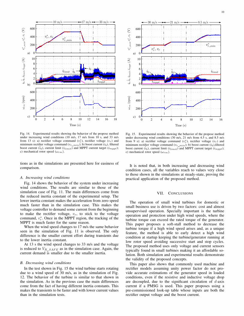
Fig. 14. Experimental results showing the behavior of the propose methodunder increasing wind conditions (10 m/s, 17 m/s from 10 s, and 33 m/sfrom 13 s): a) rectifier voltage command (v∗r ), rectifier voltage (vr) andminimum rectifier voltage command (vr min); b) boost current (ib), filteredboost current (ib), current limit (ilimit) and MPPT current target (imppt);c) mechanical rotor speed (ωrm).
tions as in the simulations are presented here for easiness ofcomparison.
A. Increasing wind conditionsFig. 14 shows the behavior of the system under increasing
wind conditions. The results are similar to those of thesimulation case of Fig. 11. The main differences come fromthe reduced inertia constant of the experimental setup. Thelower inertia constant makes the acceleration from zero speedmuch faster than in the simulation case. This makes thevoltage controller to demand some current from the beginningto make the rectifier voltage, vr, to stick to the voltagecommand, v∗r . Once in the MPPT region, the tracking of theMPPT is much faster for the same reason.
When the wind speed changes to 17 m/s the same behaviorseen in the simulation of Fig. 11 is observed. The onlydifference is the smaller current effort during transients dueto the lower inertia constant.
At 13 s the wind speed changes to 33 m/s and the voltageis reduced to VR SAFE as in the simulation case. Again, thecurrent demand is smaller due to the smaller inertia.
B. Decreasing wind conditionsIn the test shown in Fig. 15 the wind turbine starts rotating
due to a wind speed of 30 m/s, as in the simulation of Fig.12. The behavior of the turbine is similar to that shown inthe simulation. As in the previous case the main differencescome from the fact of having different inertia constants. Thismakes the transients to be faster and with lower current valuesthan in the simulation tests.
0
200
400
600
v∗ r
min,v
∗ r,vr(V
)
v∗r min
v∗r , vr
30 m/s 21 m/s 8.5 m/s
0
2
4
6
8
10
i b,i
b,i
limit,i
mppt(A
)
ib ib ilimit
imppt
a)
b)
c)0 2 4 6 8 10 12 14 16
0
200
400
600
Time (s)ωrm(rpm)
Fig. 15. Experimental results showing the behavior of the propose methodunder decreasing wind conditions (30 m/s, 21 m/s from 4.5 s, and 8.5 m/sfrom 9 s): a) rectifier voltage command (v∗r ), rectifier voltage (vr) andminimum rectifier voltage command (vr min); b) boost current (ib),filteredboost current (ib), current limit (ilimit) and MPPT current target (imppt);c) mechanical rotor speed (ωrm).
It is noted that, in both increasing and decreasing windcondition cases, all the variables reach to values very closeto those shown in the simulations at steady-state, proving thepractical application of the proposed method.
VII. CONCLUSIONS
The operation of small wind turbines for domestic orsmall business use is driven by two factors: cost and almostunsupervised operation. Specially important is the turbineoperation and protection under high wind speeds, where theturbine torque can exceed the rated torque of the generator.This paper proposes a soft-stall method to decrease theturbine torque if a high wind speed arises and, as a uniquefeature, the method is able to early detect a high windcondition at startup keeping the turbine/generator running atlow rotor speed avoiding successive start and stop cycles.The proposed method uses only voltage and current sensorstypically found in small turbines making it an affordable so-lution. Both simulation and experimental results demonstratethe validity of the proposed concepts.
This paper also shows that commonly used machine andrectifier models assuming unity power factor do not pro-vide accurate estimations of the generator speed in loadedconditions, even if the resistive and inductive voltage dropare decoupled, due to the significant circulation of d-axiscurrent if a PMSG is used. This paper proposes using apre-commissioned look-up table whose inputs are both therectifier output voltage and the boost current.

11
REFERENCES
[1] W. Kellogg, M. Nehrir, G. Venkataramanan, and V. Gerez, “Generationunit sizing and cost analysis for stand-alone wind, photovoltaic, andhybrid wind/PV systems,” IEEE Transactions on Energy Conversion,vol. 13, no. 1, pp. 70–75, Mar. 1998.
[2] P. Gipe, Wind Power: Renewable Energy for Home, Farm, andBusiness, 2nd Edition. Chelsea Green Publishing, Apr. 2004.
[3] A. C. Orrell, H. E. Rhoads-Weaver, L. T. Flowers, M. N.Gagne, B. H. Pro, and N. A. Foster, “2013 Distributed WindMarket Report,” Pacific Northwest National Laboratory (PNNL),Richland, WA (US), Tech. Rep., 2014. [Online]. Available:http://www.osti.gov/scitech/biblio/1158500
[4] J. Benjanarasut and B. Neammanee, “The d-, q- axis control techniqueof single phase grid connected converter for wind turbines with MPPTand anti-islanding protection,” in 2011 8th International Conferenceon Electrical Engineering/Electronics, Computer, Telecommunicationsand Information Technology (ECTI-CON). IEEE, May 2011, pp.649–652.
[5] M. Arifujjaman, “Modeling, simulation and control of grid connectedPermanent Magnet Generator (PMG)-based small wind energy con-version system,” in Electric Power and Energy Conference (EPEC),2010 IEEE, Aug. 2010, pp. 1 –6.
[6] H. Wang, C. Nayar, J. Su, and M. Ding, “Control and Interfacingof a Grid-Connected Small-Scale Wind Turbine Generator,” EnergyConversion, IEEE Transactions on, vol. 26, no. 2, pp. 428 –434, Jun.2011.
[7] C. Lumbreras, J. Guerrero, P. Garcia, F. Briz, and D. Diaz, “De-velopment and testing of a micro-wind generating system,” in 2013International Conference on New Concepts in Smart Cities: FosteringPublic and Private Alliances (SmartMILE), Dec. 2013, pp. 1–6.
[8] A. Ahmed, L. Ran, and J. Bumby, “New Constant Electrical PowerSoft-Stalling Control for Small-Scale VAWTs,” IEEE Transactions onEnergy Conversion, vol. 25, no. 4, pp. 1152–1161, Dec. 2010.
[9] S.-H. Song, S. il Kang, and N. kun Hahm, “Implementation andcontrol of grid connected AC-DC-AC power converter for variablespeed wind energy conversion system,” in Applied Power ElectronicsConference and Exposition, 2003. APEC ’03. Eighteenth AnnualIEEE, vol. 1, 2003, pp. 154–158 vol.1.
[10] Y. Y. Xia, J. E. Fletcher, S. J. Finney, K. H. Ahmed, and B. W.Williams, “Torque ripple analysis and reduction for wind energyconversion systems using uncontrolled rectifier and boost converter,”IET Renewable Power Generation, vol. 5, no. 5, pp. 377–386, Sep.2011.
[11] Y. Xia, K. Ahmed, and B. Williams, “A New Maximum Power PointTracking Technique for Permanent Magnet Synchronous GeneratorBased Wind Energy Conversion System,” IEEE Transactions onPower Electronics, vol. 26, no. 12, pp. 3609–3620, Dec. 2011.
[12] H.-G. Park, S.-H. Jang, D.-C. Lee, and H.-G. Kim, “Low-cost convert-ers for micro wind turbine systems using PMSG,” in 7th InternatonalConference on Power Electronics, 2007. ICPE ’07, Oct. 2007, pp.483–487.
[13] N. T. Hai, S.-H. Jang, H.-G. Park, and D.-C. Lee, “Sensorless controlof PM synchronous generators for micro wind turbines,” in Powerand Energy Conference, 2008. PECon 2008. IEEE 2nd International,2008, pp. 936–941.
[14] E. Muljadi, T. Forsyth, and C. P. Butterfield, “Soft-stall control versusfurling control for small wind turbine power regulation,” NationalRenewable Energy Lab., Golden, CO (United States), Tech. Rep.,1998. [Online]. Available: http://www.osti.gov/scitech/biblio/661575
[15] S. Jiao, G. Hunter, V. Ramsden, and D. Patterson, “Control systemdesign for a 20 kW wind turbine generator with a boost converterand battery bank load,” in Power Electronics Specialists Conference,2001. PESC. 2001 IEEE 32nd Annual, vol. 4, 2001, pp. 2203–2206vol. 4.
[16] Y. Matsui, A. Sugawara, S. Sato, T. Takeda, and K. Ogura, “BrakingCircuit of Small Wind Turbine Using NTC Thermistor under NaturalWind Condition,” in Power Electronics and Drive Systems, 2007.PEDS ’07. 7th International Conference on, Nov. 2007, pp. 910 –915.
[17] C.-C. Hua and C.-Z. He, “Design and implementation of a digitalpower converter for wind energy conversion,” in 2011 6th IEEE Con-
ference on Industrial Electronics and Applications (ICIEA). IEEE,Jun. 2011, pp. 1398–1402.
[18] K.-Y. Lo, Y.-M. Chen, and Y.-R. Chang, “MPPT Battery Chargerfor Stand-Alone Wind Power System,” IEEE Transactions on PowerElectronics, vol. 26, no. 6, pp. 1631–1638, Jun. 2011.
[19] Y.-L. Juan, “An Integrated-Controlled AC/DC Interface for MicroscaleWind Power Generation Systems,” IEEE Transactions on PowerElectronics, vol. 26, no. 5, pp. 1377–1384, May 2011.
[20] J. Chen, J. Chen, and C. Gong, “New Overall Power Control Strategyfor Variable-Speed Fixed-Pitch Wind Turbines Within the Whole WindVelocity Range,” IEEE Transactions on Industrial Electronics, vol. 60,no. 7, pp. 2652–2660, Jul. 2013.
[21] Z. Chen, J. Guerrero, and F. Blaabjerg, “A Review of the State of theArt of Power Electronics for Wind Turbines,” IEEE Transactions onPower Electronics, vol. 24, no. 8, pp. 1859–1875, Aug. 2009.
[22] Z. Chen, X. Xiao, H. Wang, and M. Liu, “Analysis of convertertopological structure for direct-drive wind power system with PMSG,”in 2010 International Conference on Power System Technology (POW-ERCON). IEEE, Oct. 2010, pp. 1–5.
[23] M. Abarzadeh, H. Madadi, and L. Chang, “Power Electronicsin Small Scale Wind Turbine Systems,” in Advancesin Wind Power, R. Carriveau, Ed. InTech, Nov. 2012.[Online]. Available: http://www.intechopen.com/books/advances-in-wind-power/power-electronics-in-small-scale-wind-turbine-systems
[24] T. R. De Freitas, P. J. Menegz, and D. S. Simonetti, “Converter topolo-gies for permanent magnetic synchronous generator on wind energyconversion system,” in Power Electronics Conference (COBEP),2011 Brazilian. IEEE, 2011, pp. 936–942. [Online]. Available:http://ieeexplore.ieee.org/xpls/abs all.jsp?arnumber=6085292
[25] Z. Dalala, Z. Zahid, and J.-S. Lai, “New overall control strategyfor wind energy conversion systems in MPPT and stall regions,” in2013 IEEE Energy Conversion Congress and Exposition (ECCE), Sep.2013, pp. 2412–2419.
[26] O. Castillo, E. Amoros, G. Sanfeliu, and L. Morales, “Average CurrentMode Control of Three-Phase Boost Rectifiers with Low HarmonicDistortion Applied to Small Wind Turbines,” in Electronics, Roboticsand Automotive Mechanics Conference, 2009. CERMA ’09., Sep.2009, pp. 446 –451.
[27] H.-G. Park, S.-H. Jang, D.-C. Lee, and H.-G. Kim, “Low-costconverters for micro wind turbine systems using PMSG,” in PowerElectronics, 2007. ICPE ’07. 7th Internatonal Conference on, 2007,pp. 483–487.
[28] A. Sugawara, K. Yamamoto, T. Yoshimi, S. Sato, A. Tsurumaki, andT. Ito, “Research for Electric Brake Using NTC Thermistors on MicroWind Turbine,” in Power Electronics and Motion Control Conference,2006. EPE-PEMC 2006. 12th International, Sep. 2006, pp. 1597 –1601.
[29] J. Hui, A. Bakhshai, and P. Jain, “An Energy Management Schemewith Power Limit Capability and an Adaptive Maximum Power PointTracking for Small Standalone PMSG Wind Energy Systems,” IEEETransactions on Power Electronics, vol. PP, no. 99, pp. 1–1, 2015.
[30] S. Heier, Grid Integration of Wind Energy Conversion Systems, 2nd ed.Wiley, Jun. 2006.
[31] M. Saitou, N. Matsui, and T. Shimizu, “A control strategy of single-phase active filter using a novel d-q transformation,” in IndustryApplications Conference, 2003. 38th IAS Annual Meeting. ConferenceRecord of the, vol. 2, Oct. 2003, pp. 1222–1227 vol.2.