1 chapter 6 co-synthesis techniques. 2 cosynthesis methodical approach to system implementations...
TRANSCRIPT

1
Chapter 6Co-synthesis Techniques

2
Cosynthesis
Methodical approach to system implementations using automated synthesis-oriented techniques
Methodology and performance constraints determine partitioning into hardware and software implementations
The result is “optimal” system that benefits from analysis of hardware/software design trade-off analysis

3
Cosynthesis Approach to System Implementation
MemoryBehavioral
Specification and Performance criteria
SystemInput
Per
form
ance
Cost
MixedImplementation
Pure SW
Pure HW
Constraints
[Gupta93]
SystemOutput
© IEEE 1993

4
Co-synthesis
Implementation of hardware and software components after partitioning
Constraints and optimization criteria similar to those for partitioning
Area and size traded-off against performance
Cost considerations

5
Synthesis Flow
HW synthesis of dedicated units
– Based on research or commercial standard synthesis tools
SW synthesis of dedicated units (processors)
– Based on specialized compiling techniques
Interface synthesis
– Definition of HW/SW interface and synchronization
– Drivers of peripheral devices
6
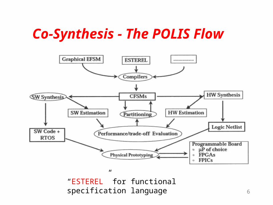
Co-Synthesis - The POLIS Flow
“ESTEREL” for functional specification language

7
Hardware DesignMethodology
Hardware Design Process:Waterfall Model
HardwareRequirements
PreliminaryHardware
Design
DetailedHardware
DesignFabrication Testing

8
Hardware DesignMethodology (Cont.)
Use of HDLs for modeling and simulation
Use of lower-level synthesis tools to derive register transfer and lower-level designs
Use of high-level hardware synthesis tools
– Behavioral descriptions
– System design constraints
Introduction of synthesis for testability at all levels

9
Hardware Synthesis
Definition– The automatic design and implementation of hardware from
a specification written in a hardware description language
Goals/benefits
– To quickly create and modify designs
– To support a methodology that allows for multiple design alternative consideration
– To remove from the designer the handling of the tedious details of VLSI design
– To support the development of correct designs

10
Hardware Synthesis Categories
Algorithm synthesis– Synthesis from design requirements to control-flow behavior
or abstract behavior– Largely a manual process
Register-transfer synthesis– Also referred to as “high-level” or “behavioral” synthesis– Synthesis from abstract behavior, control-flow behavior, or
register-transfer behavior (on one hand) to register-transfer structure (on the other)
– Logic synthesis– Synthesis from register-transfer structures or Boolean
equations to gate-level logic (or physical implementations using a predefined cell or IC library)

11
Hardware Synthesis Process Overview
BehavioralSimulation
Optional RTLSimulation
BehavioralSynthesis
Synthesis &Test Synthesis
Gate-levelSimulation
Gate-levelAnalysis
Place and Route
Specification Implementation
Verification
Silicon Vendor
Silicon
BehavioralFunctional
RTLFunctional
Gate
Layout

12
HW Synthesis
(3)
ICOS
Architecture specs
Performance specs
Synthesis specs
Specification Input
Specification Analysis
Class Hierarchy
Specification Error?
Yes
Initialization:
AddDH(root), AppendDQ(root)
PopDQ
Component
Design ...
DQempty?
No
No
No
No
Yes
rollback possible?
design
complete?
Yes
Yes
Synthesis Rollback
Simulation and Performance Evaluation
Output Best Architecture
Error: Synthesis Impossible
Component
Design
Component
Design
Component
Design
(2)
(1)
(1) Specification Analysis Phase (2) Concurrent Design Phase (3) System Integration Phase
Stop
1. Specification Analysis
2. Concurrent Design
3. System Integration

13
Software DesignMethodology
Software Design Process:Waterfall Model
SoftwareRequirements
Software Design
Coding Testing Maintenance

14
Software DesignMethodology (Cont.)
Software requirements includes both– Analysis– Specification
Design: 2 levels:– System level - module specs.– Detailed level - process design language (PDL) used
Coding - in high-level language– C/C++
Maintenance - several levels– Unit testing– Integration testing– System testing– Regression testing– Acceptance testing

15
Software Synthesis
Definition: the automatic development of correct and efficient software from specifications and reusable components
Goals/benefits
– To Increase software productivity
– To lower development costs
– To Increase confidence that software implementation satisfies specification
– To support the development of correct programs

16
Why UseSoftware Synthesis?
Software development is becoming the major cost driver in fielding a system
To significantly improve both the design cycle time and life-cycle cost of embedded systems, a new software design methodology, including automated code generation, is necessary
Synthesis supports a correct-by-construction philosophy
Techniques support software reuse

17
Why Software Synthesis?
More software high complexity need for automatic design (synthesis)
Eliminate human and logical errors
Relatively immature synthesis techniques for software
Code optimizations
– size
– efficiency
Automatic code generation

18
Software Synthesis Flow Diagram for
Embedded System with Time Petri-Net
System Software
Specification
Modeling System
Software with Time Petri
Net
Task Scheduling
Code Generation
Code Execution on an
Emulation Board
Test Report
Vehicle Parking
Management System
Feedback and Modification

19
Automatically Generate CODE Real-Time Embedded System Model?
Set of concurrent tasks with memory and timing constraints!
How to execute in an embedded system (e.g. 1 CPU, 100 KB Mem)? Task Scheduling!
How to generate code?Map schedules to software code!
Code optimizations?Minimize size, maximize efficiency!

20
Software SynthesisCategories
Language compilers
– ADA and C compilers
– YACC - yet another compiler compiler
– Visual Basic
Domain-specific synthesis
– Application generators from software libraries

21
Software Synthesis Examples
Mentor Graphics Concurrent Design Environment System
– Uses object-oriented programming (written in C++)– Allows communication between hardware and software
synthesis tools Index Technologies Excelerator and Cadre’s
Teamwork Toolsets– Provide an interface with COBOL and PL/1 code generators
KnowledgeWare’s IEW Gamma– Used in MIS applications– Can generate COBOL source code for system designers
MCCI’s Graph Translation Tool (GrTT)– Used by Lockheed Martin ATL– Can generate ADA from Processing Graph Method (PGM)
graphs

22
Software Synthesis Tool:
The Design of Synthesis Tool for Interrupted-based Embedded Software

23
Motivation
System Complexity Time to Market Hardware-Software Co-design Methodology Embedded Software Synthesis Tools
Text-Edit User-Interface
System Model Interrupt Behavior
Introduction

24
Designing of a Synthesis Tool
System Model Interrupt Time Petri Net, ITPN
Scheduling Interrupt-Based Quasi-Dynamic Scheduling, IQDS
Code Generation Microcontroller(89c51) C Program Code
Real-Time Embedded Software Synthesis Tool Graphical User-Interface
Introduction

25
System Framework
GUI
Software Synthesis
ITPN
IQDS
Code Generation
Introduction
26
Definition for ITPN
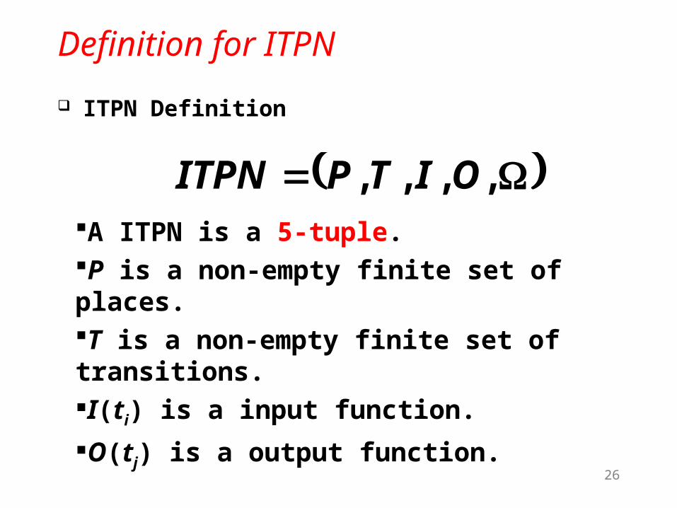
ITPN Definition
System Model
, , , , OITPITPNA ITPN is a 5-tuple.P is a non-empty finite set of places.T is a non-empty finite set of transitions.I(ti) is a input function.
O(tj) is a output function.

27
Definition for ITPN
Ω:Ω(t)=(α, β, γ) α:Earliest Firing Time, EFT. β:Latest Firing Time, LFT. γ:The type of interrupt for 8051.

28
A ITPN Example
System Model
t1(α1, β1, γ1) p1
p2
p3
t2(α2, β2, γ2)
t3(α3, β3, γ3)
Initial Place
End Place
End Place

29
Interrupt-Based Quasi-Dynamic Scheduling (IQDS)
Scheduling & Code Generation
Step2: Decompose the ITPN into two parts : static scheduling and choice block (CB)
Step3: Search the routing path (choice clock set, CBS) for each CBStep4: Derive all routing path from Initial PlaceStep5: Check the real-time constraints for all
routing path
Step1: Find the Initial Place, End Place, and Choice Block
30
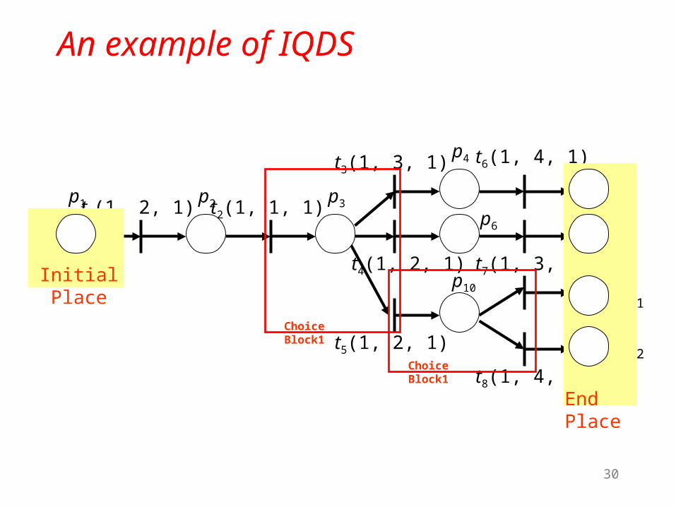
An example of IQDS
Scheduling & Code Generation
p4
p1 p2 p3p5
p6 p7
p10 p11
p12
t1(1, 2, 1) t2(1, 1, 1)
t4(1, 2, 1)
t3(1, 3, 1)
t5(1, 2, 1)
t6(1, 4, 1)
t7(1, 3, 1)
t8(1, 4, 1)
Choice Block1
Choice Block1
Initial Place
End Place

31Scheduling & Code Generation
An example of IQDS (cont.)
Route Extended
Present Route
t1t2
CBS1:
t3
t4
t5
Result
t1t2 t3
t1t2 t4
t1t2 t5
Present Route
t1t2 t3
t1t2 t4
t1t2 t5
CBS2:t8
t9
Static Route
t6
t7
Result
t1t2 t3 t6
t1t2 t4 t7
t1t2 t5 t8
t1t2 t5 t9

32Scheduling & Code Generation
An example of IQDS (cont.)
Result
t1t2 t3 t6
t1t2 t4 t7
t1t2 t5 t8
t1t2 t5 t9
Real_Time_Check
Schedulable
Not Schedulable
0 α β
0 RouteTimeMax SystemPeriod

33
Code Generation
Step2: Print transition’s content from Initial Place
Step3: Print “if then else”
Step4: Combine main_function, sub_function, and ISR
Step1: Differentiate ISR, main_function, and
sub_function
34
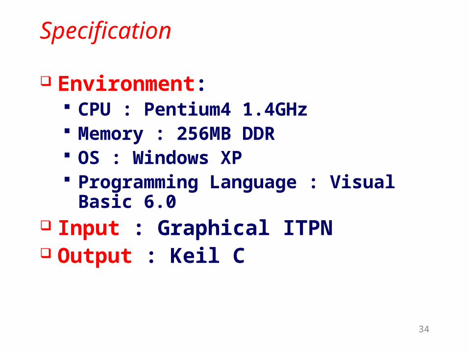
Specification
Environment: CPU : Pentium4 1.4GHz Memory : 256MB DDR OS : Windows XP Programming Language : Visual Basic
6.0 Input : Graphical ITPN Output : Keil C
Software Synthesis Tool

35
Graphical User Interface
Software Synthesis Tool
ITPN Edit, Scheduling and Code Generation
SchedulingCode
Generation
ITPN Edit

36
Real-time Stepping Motor Control (RSMC)
System Function: Control Stepping Motor speed and
direction. INT0, Timer1: Motor’s speed control. Timer0 : Motor’s direction control.
Examples

37
Block Diagram of RSMC
Example
Micro- controller
89C51
Input Device
Display
Stepping Motor
Driving Circuit

38
ITPN Model for RSMC Main Function
Example
p1 p2
p3
p4
p5
p6
p7
p8
t1(2, 35, 13)
t2(2, 35, 13)
t3(2, 35, 13)
t4(2, 35, 13)
t5(2, 35, 13)
t7(2, 35, 13)
t6(2, 35, 13)
t1 : Capture Keypad register. t2 , t3 : Turn on Stepping Motor.t4 : Shut off Stepping Motor. t5 : Set positive direct.t6 : Set opposite direction. t7 : Stop LED on.

39

40
ITPN Model for RSMC (cont.) Timer0 ISR
Example
p9 p10 p11t8(2, 2, 32) t9(6, 6, 32)
t8 : Reset t9 : Scan Keypad

41

42
ITPN Model for RSMC (cont.) Timer1 ISR
Example
p12 p14p13
p15 p17
p16
t10(2, 2, 32)
t13(0, 0, 32)
t11(2, 2, 32)
t12(2, 2, 32) t14(9, 9, 32)
t10 : Reset t11 : Increase countert12 : Reset count t13 : Undot14 : Control stepping motor

43

44
ITPN Model for RSMC(cont.) INT0 ISR
Example
p18 p19
p21
p20
p23
p22
p24
p25
t15(2, 2, 32)
t17(2, 2, 32)
t20(2, 2, 32)
t19(2, 2, 32)
t16(2, 2, 32)
t21(0, 0, 32)
t18(0, 0, 32)
t15 : Get the key (Speed up or down)t16 : Check Max speedt17 : Check Min speedt18 : Undot19 : Speed upt20 : Speed downt21 : Undo

45

46
Scheduling and Code Generation
Example

47
Real Time Constraints
Example
Interrupt ISR’s time
INT0 8
Timer0 8
Timer1 15
ISR’s time : β-α > 31 (8+8+15=31)
Cycle Time > 105

48
Emulation
Platform Architecture
Example
FPGA/CPLDChip
Single ChipMicrocontroller
Memory
KeyboardLCD
Display
LED and7-Segment
Display
InputSwitch

49
Summary
Extended system model called “Interrupt Time Petri Net, ITPN”
An Interrupt-Based Quasi-Dynamic Scheduling, IQDS is proposed
Generate a microcontroller (8051) C program code
Graphical user interface make the tool more user-friendly
Conclusion

50
END