1 chapter 18 protocols for qos support. chapter 18: protocols for qos support 2 introduction modern...
TRANSCRIPT

1
Chapter 18Chapter 18
Protocols for QoS Protocols for QoS SupportSupport

Chapter 18: Protocols for QoS Support2
IntroductionIntroduction Modern internet Modern internet applicationsapplications demand demand
services not provided by a best-effort services not provided by a best-effort service modelservice model
The The TCP/IP infrastructureTCP/IP infrastructure has been has been enhanced to address the needenhanced to address the need– increased capacity and data ratesincreased capacity and data rates– efficient multicasting techniques (Chap. 15)efficient multicasting techniques (Chap. 15)– QoS capabilities added (Chap. 17)QoS capabilities added (Chap. 17)
Protocols are required to support the QoS Protocols are required to support the QoS enhancements to the infrastructure:enhancements to the infrastructure:– RSVPRSVP for reservation and admission control for reservation and admission control– MPLSMPLS for traffic engineering for traffic engineering– RTPRTP for real-time application support for real-time application support

Chapter 18: Protocols for QoS Support3
Resource Reservation Resource Reservation (RSVP)(RSVP) Internet resource reservation Internet resource reservation
characteristics (characteristics (RFC 2205RFC 2205))– similar, but fundamentally different similar, but fundamentally different
from that used in connection-oriented from that used in connection-oriented networks such as ATM, frame relaynetworks such as ATM, frame relay
– soft statesoft state at routers: reserved at routers: reserved resources expire unless refreshedresources expire unless refreshed
there is no “connection” setup or there is no “connection” setup or teardown on which to base “hard” state teardown on which to base “hard” state maintenancemaintenance
– end systems must end systems must periodically renewperiodically renew their requests (default: every 30 sec.)their requests (default: every 30 sec.)

Chapter 18: Protocols for QoS Support4
RSVP Design RSVP Design CharacteristicsCharacteristicsUnicast and MulticastUnicast and MulticastSimplexSimplexReceiver-initiated reservationReceiver-initiated reservationMaintains soft stateMaintains soft stateDifferent reservation stylesDifferent reservation stylesTransparent operation through Transparent operation through
non-RSVP routersnon-RSVP routersSupport for IPv4 and IPv6Support for IPv4 and IPv6
Unicast and Unicast and Multicast (design Multicast (design point)point)
SimplexSimplexReceiver-initiated reservationReceiver-initiated reservationMaintains soft stateMaintains soft stateDifferent reservation stylesDifferent reservation stylesTransparent operation through Transparent operation through
non-RSVP routersnon-RSVP routersSupport for IPv4 and IPv6Support for IPv4 and IPv6

Chapter 18: Protocols for QoS Support5
Receiver-Initiated Receiver-Initiated ReservationReservation Source-initiated reservations are Source-initiated reservations are
inadequate for multicastinginadequate for multicasting– different members of same group may have different members of same group may have
different resource requirementsdifferent resource requirements– if transmission flow is divided into sub-flows, if transmission flow is divided into sub-flows,
not all members need all sub-flowsnot all members need all sub-flows– if multiple sources are transmitting for same if multiple sources are transmitting for same
group, receiver may want to select sourcegroup, receiver may want to select source– In general, QoS needs of different receivers In general, QoS needs of different receivers
may differ due to equipment, link speed, may differ due to equipment, link speed, processing speed/power or other differencesprocessing speed/power or other differences
SenderSender provides traffic characteristics, provides traffic characteristics, but but receiverreceiver requests desired QoS requests desired QoS

Chapter 18: Protocols for QoS Support6
Soft StateSoft State Values associated with a given flow is Values associated with a given flow is
temporarilytemporarily cached at the router cached at the router– based on end-system reservationbased on end-system reservation
Routing for that flow is subject to Routing for that flow is subject to changechange
End systems must End systems must periodically refreshperiodically refresh the state informationthe state information
Routers discard states not refreshedRouters discard states not refreshed within specified time limitwithin specified time limit
If a new route becomes the preferred If a new route becomes the preferred route for the flow, end systems provide route for the flow, end systems provide the reservation information to the new the reservation information to the new routers on the routerouters on the route

Chapter 18: Protocols for QoS Support7
RSVP Data Flow ConceptsRSVP Data Flow Concepts How are How are flows flows of data identified?of data identified?
– Session – identifies a flow by its Session – identifies a flow by its destination (unicast or multicast)destination (unicast or multicast)
Destination IP addressDestination IP address IP protocol identifier (e.g., TCP or UDP)IP protocol identifier (e.g., TCP or UDP) Destination port numberDestination port number
– Flowspec – describes the QoS parametersFlowspec – describes the QoS parameters Service classService class Tspec: Tspec: ttraffic characteristics of the flow (average rate, raffic characteristics of the flow (average rate,
peak rate, maximum burst size)peak rate, maximum burst size) Rspec: QoS Rspec: QoS rreservations specification of the flow (for eservations specification of the flow (for
Guaranteed Service)Guaranteed Service)
– Filter specification – defines the packets Filter specification – defines the packets in a flowin a flow
Source IP address (minimal)Source IP address (minimal) UDP/TCP source port number (optional)UDP/TCP source port number (optional) other fields (based on application)other fields (based on application)
Flow
Desc
rip
tor

Chapter 18: Protocols for QoS Support8
Example: Treatment of Example: Treatment of Packets at RouterPackets at Router
1. Packet is checked to see if it is in a defined flow
2. Packet in flow is granted the appropriate QoS for that flow
3. Packets are handled (queued and serviced) per QoS parameters

Chapter 18: Protocols for QoS Support9
RSVP OperationRSVP Operation
R1, R2, R3, R4: forwarding routersG1, G2, G3: multicast receiversS1, S2: multicast senders

Chapter 18: Protocols for QoS Support10
RSVP Reservation RSVP Reservation OperationOperation
Destination(s)/Destination(s)/Receiver(s)Receiver(s)
Source(s)/Source(s)/Senders(s)Senders(s)
RouterRouter
Reservation actions at router:Reservation actions at router:1.1. Admission control – verify requested Admission control – verify requested
resources are availableresources are available2.2. Policy control – verify permissionsPolicy control – verify permissions3.3. Set up classifier and scheduler to Set up classifier and scheduler to
provide requested Q0Sprovide requested Q0S4.4. Forward request upstream (aggregate Forward request upstream (aggregate
as required)as required)
RSVP Reservation (RESV) MessagesRSVP Reservation (RESV) Messages

Chapter 18: Protocols for QoS Support11
Reservation StylesReservation Styles How resource reservations are How resource reservations are
aggregated/mergedaggregated/merged for multiple for multiple receivers in the same multicast groupreceivers in the same multicast group
Two options, specified in the receivers’ Two options, specified in the receivers’ reservation requestsreservation requests– Reservation attributeReservation attribute: reservation is : reservation is
sharedshared over flows from multiple senders, over flows from multiple senders, or or distinctdistinct for each sender for each sender
– Sender selectionSender selection: : explicitexplicit list or list or wildcardwildcard Three reservation styles are defined…Three reservation styles are defined…

Chapter 18: Protocols for QoS Support12
RSVP Styles - Reservation RSVP Styles - Reservation Attributes and Sender Attributes and Sender SelectionSelection
Fixed-Filter:• Specifies a distinct
reservation for each sender and an explicit list of senders
• Symbolic representation: FF(S1{Q1}, S2{Q2}, …)
Shared-Explicit:• Specifies that a single
resource reservation is to be shared by an explicit list of senders
• Symbolic representation: SE(S1, S2, … {Q})
Wildcard-Filter:• Specifies that a single
resource reservation is to be shared by all senders to this address
• Symbolic representation: WF(*{Q})
per session
per
sender

Chapter 18: Protocols for QoS Support13
Reservation Styles: Reservation Styles: ExampleExample
S1
S2
S3
MulticastGroupReceivers
MulticastGroup
Sources
Router
withRSVP
capability

Chapter 18: Protocols for QoS Support14
RSVP Protocol MechanismsRSVP Protocol Mechanisms Two basic message types:Two basic message types:
– ResvResv: propagates upstream from receivers to establish : propagates upstream from receivers to establish router soft states (router soft states (resource reservationsresource reservations) for a multicast ) for a multicast group, merging as required. Message carries a merged group, merging as required. Message carries a merged flowspecflowspec..
– PathPath: issued by senders to establish : issued by senders to establish reverse-hopreverse-hop (upstream) path back to a source from group members(upstream) path back to a source from group members
15
QoS Protocols (cont.)QoS Protocols (cont.)

Chapter 18: Protocols for QoS Support16
Multiprotocol Label Multiprotocol Label SwitchingSwitching
““MPLS: The intelligence of MPLS: The intelligence of routing with the performance routing with the performance of switching.”of switching.”

Chapter 18: Protocols for QoS Support17
Multiprotocol Label Multiprotocol Label SwitchingSwitching
MPLS GoalMPLS Goal: provide : provide ATM-like traffic ATM-like traffic management and management and QoS within IP-based QoS within IP-based networksnetworks
RealityReality: provides : provides an approach which an approach which reduces per-packet reduces per-packet processing required processing required at routers, thereby at routers, thereby enhancing IP enhancing IP routing routing performanceperformance
Significant Significant new new capabilitiescapabilities are are introduced in introduced in MPLS:MPLS:1.1. support for support for
connection-connection-oriented QoSoriented QoS
2.2. Traffic Traffic engineeringengineering
3.3. VPN supportVPN support4.4. multiprotocol multiprotocol
supportsupport RFC 3031RFC 3031 issued issued
in January 2001in January 2001

Chapter 18: Protocols for QoS Support18
MPLS in PracticeMPLS in Practice High-speed IP backbonesHigh-speed IP backbones Legacy ATM networksLegacy ATM networks MPLS-capable ATM networksMPLS-capable ATM networks Optical networksOptical networks Frame relay networksFrame relay networks
– Most prevalent usage is for transporting IP Most prevalent usage is for transporting IP data over these networks with low data over these networks with low overhead/latency, often to implement a overhead/latency, often to implement a VPN for IP trafficVPN for IP traffic

Chapter 18: Protocols for QoS Support19
MPLS in PracticeMPLS in Practice improves packet-forwarding performanceimproves packet-forwarding performance in the in the
networknetwork – MPLS enhances and simplifies packet forwarding MPLS enhances and simplifies packet forwarding
through routers using Layer-2 switching paradigms. through routers using Layer-2 switching paradigms. – MPLS is simple, which allows for easy implementation. MPLS is simple, which allows for easy implementation. – MPLS increases network performance because it MPLS increases network performance because it
enables routing by switching at wireline speeds.enables routing by switching at wireline speeds.
supports QoS and CoS for supports QoS and CoS for service differentiation service differentiation – MPLS uses traffic-engineered path setup and helps MPLS uses traffic-engineered path setup and helps
achieve service-level guarantees. achieve service-level guarantees. – MPLS incorporates provisions for constraint-based and MPLS incorporates provisions for constraint-based and
explicit path setup.explicit path setup.
supports network scalabilitysupports network scalability – MPLS can be used to MPLS can be used to avoid the overlay performance avoid the overlay performance
problem associatedproblem associated with meshed IP–ATM networks. with meshed IP–ATM networks.

Chapter 18: Protocols for QoS Support20
MPLS in PracticeMPLS in Practice integrates IP and ATMintegrates IP and ATM in the network in the network
– MPLS provides a bridge between access IP and MPLS provides a bridge between access IP and core ATM. core ATM.
– MPLS can reuse existing router/ATM switch MPLS can reuse existing router/ATM switch hardware, effectively joining the two disparate hardware, effectively joining the two disparate networks.networks.
builds builds interoperable networksinteroperable networks – MPLS is a standards-based solution that achieves MPLS is a standards-based solution that achieves
synergy between IP and ATM networks. synergy between IP and ATM networks. – MPLS facilitates IP–over-synchronous optical MPLS facilitates IP–over-synchronous optical
network (SONET) integration in optical switching. network (SONET) integration in optical switching. – MPLS helps build scalable VPNs with traffic-MPLS helps build scalable VPNs with traffic-
engineering capability.engineering capability.

Chapter 18: Protocols for QoS Support21
MPLS Terminology MPLS Terminology SummarySummary
Per RFC 3031

Chapter 18: Protocols for QoS Support22
MPLS OperationMPLS Operation using an interior routing protocol (like OSPF), establish a path (LSP) in advance for a given FEC and establish the QoS parameters for the FEC. Labels are assigned for each FEC.
packets entering at ingress LSR are assigned to an appropriate FEC and a label is attached
at each LSR along the LSP, the incoming label is removed and an outgoing label is attached
the egress LSR strips the label and forwards the packet to its final destination

Chapter 18: Protocols for QoS Support23
MPLS OperationMPLS Operation

Chapter 18: Protocols for QoS Support24
MPLS OperationMPLS Operation MPLS FEC can be determined by a number MPLS FEC can be determined by a number
of of parametersparameters::– source/destination IP addressessource/destination IP addresses– port numbersport numbers– IP protocol IDIP protocol ID– DS codepointDS codepoint– IPv6 flow labelIPv6 flow label
Forwarding between LSRs requires only Forwarding between LSRs requires only simple mapping between label values and simple mapping between label values and next hop addressesnext hop addresses– note: labels have note: labels have local significancelocal significance only only
A particular PHB can be assigned for a A particular PHB can be assigned for a given FEC at each LSRgiven FEC at each LSR

Chapter 18: Protocols for QoS Support25
MPLS Advantages over MPLS Advantages over Network Layer ForwardingNetwork Layer Forwarding
MPLS forwarding can be done by MPLS forwarding can be done by high-speed high-speed switchesswitches that may not be capable of IP packet that may not be capable of IP packet analysis/handlinganalysis/handling
Forwarding behavior (the LSP) can be based Forwarding behavior (the LSP) can be based on information other than that in the IP headeron information other than that in the IP header
Forwarding behavior can be Forwarding behavior can be based on network based on network ingress pointingress point
FEC determination can be FEC determination can be arbitrarily complexarbitrarily complex since it is done only once – at ingresssince it is done only once – at ingress
Paths for Paths for traffic can be “engineered”traffic can be “engineered” in in advance to balance load traffic or provide advance to balance load traffic or provide different levels of serviced for different FECsdifferent levels of serviced for different FECs

Chapter 18: Protocols for QoS Support26
MPLS Packet ForwardingMPLS Packet Forwarding
Label stacking?

Chapter 18: Protocols for QoS Support27
MPLS Label Format & MPLS Label Format & PlacementPlacement
Data Link Data Link FrameFrame
IEEE 802 IEEE 802 MAC FrameMAC Frame
ATMATMCellCell
Frame RelayFrame RelayFrameFrame

Chapter 18: Protocols for QoS Support28
MPLS Path SelectionMPLS Path Selection
Class of Service
Traffic Engineering

Chapter 18: Protocols for QoS Support29
MPLS Path (Route) MPLS Path (Route) SelectionSelectionTwo options specified in RFC 3031:Two options specified in RFC 3031:
– hop-by-hophop-by-hop routing routing makes use of ordinary routing protocols, makes use of ordinary routing protocols,
like OSPFlike OSPF does not readily support traffic engineering does not readily support traffic engineering
or routing based on policy/priorityor routing based on policy/priority
– explicitexplicit routing routing single designated LSR, usually an ingress single designated LSR, usually an ingress
or egress LSR, specifies all LSRs in a route or egress LSR, specifies all LSRs in a route for a given FECfor a given FEC
with “loose explicit routing” only some of with “loose explicit routing” only some of the LSRs are specifiedthe LSRs are specified

Chapter 18: Protocols for QoS Support30
MPLS Label DistributionMPLS Label DistributionRFC 3031 does not define or RFC 3031 does not define or
depend on a specific depend on a specific label label distribution protocol distribution protocol – several are – several are defineddefined– MPLS-LDP (RFC 3036)MPLS-LDP (RFC 3036)– RSVP-TE (RFC 3209) RSVP-TE (RFC 3209) – MPLS-BGP MPLS-BGP – MPLS-RSVP-TUNNELSMPLS-RSVP-TUNNELS
Labels are distributed (bound) in a Labels are distributed (bound) in a downstreamdownstream path of LSRs in an LSP path of LSRs in an LSP
Labels must be Labels must be uniqueunique on each on each hop between pairs of LSRs )local hop between pairs of LSRs )local significance)significance)
Recent focus of IETF efforts

31
Real-Time Transport Real-Time Transport Protocol (RTP)Protocol (RTP)

Chapter 18: Protocols for QoS Support32
Real-Time Traffic FlowReal-Time Traffic Flow
Real-Time Real-Time DistributedDistributedApplication:Application:
• Source generates data stream at a constant rate
• One or more destinations must deliver that data to an application at the same constant rate

Chapter 18: Protocols for QoS Support33
Time relationship of real-time traffic
From Data Communication and Networks, Forouzan, 4th Edition
Real-time traffic requires preservation of the Real-time traffic requires preservation of the time relationshiptime relationship between packets of a session. between packets of a session.

Chapter 18: Protocols for QoS Support34
From Data Communication and Networks, Forouzan, 4th Edition
Jitter (variation in delay)
Jitter is introduced due top the Jitter is introduced due top the variable variable component of delaycomponent of delay in packet switched networks. in packet switched networks.

Chapter 18: Protocols for QoS Support35
From Data Communication and Networks, Forouzan, 4th Edition
Timestamp
TimestampingTimestamping packets can allow packets can allow reconstruction reconstruction of original time relationshipof original time relationship at the receiver. at the receiver.

Chapter 18: Protocols for QoS Support36
From Data Communication and Networks, Forouzan, 4th Edition
Playback Buffer
A A playback bufferplayback buffer at the receiver is used to at the receiver is used to sequence/time the release of data to the sequence/time the release of data to the
application.application.
threshold
threshold

Chapter 18: Protocols for QoS Support37
TCP/UDP for Real-Time?TCP/UDP for Real-Time? TCPTCP
– point-to-point, connection-oriented, so point-to-point, connection-oriented, so not suitable for multicastnot suitable for multicast
– includes includes retransmission mechanismsretransmission mechanisms for for lost segments, which often conflicts lost segments, which often conflicts with real-time application requirementwith real-time application requirement
– no no segment timing informationsegment timing information available available
UDPUDP– no no segment timing informationsegment timing information available available
or other general purpose real time toolsor other general purpose real time tools

Chapter 18: Protocols for QoS Support38
Real-Time Transport Real-Time Transport Protocol (RTP)Protocol (RTP)
Defined in Defined in RFC 3550RFC 3550 to provide mechanisms needed to provide mechanisms needed to support real-time traffic in IP-based networks, to support real-time traffic in IP-based networks, – primarily to satisfy the needs of multi- participant multimedia primarily to satisfy the needs of multi- participant multimedia
conferences conferences Best suited for Best suited for soft real-timesoft real-time communication communication
– Lacks mechanisms to support hard real-time traffic Lacks mechanisms to support hard real-time traffic (i.e., traffic with no loss tolerance, minimal jitter)(i.e., traffic with no loss tolerance, minimal jitter)
Closely coupled with the Closely coupled with the application layerapplication layer in the in the Internet protocol stack (typically, above Internet protocol stack (typically, above UDPUDP))
Two protocolsTwo protocols make up RTP: make up RTP:– RTPRTP, a data transfer protocol (carries the data), a data transfer protocol (carries the data)– RTCPRTCP, a control protocol (carries session/QoS info), a control protocol (carries session/QoS info)

Chapter 18: Protocols for QoS Support39
RTP Architecture Concepts RTP Architecture Concepts
From Data Communication and Networks, Forouzan, 4th Edition

Chapter 18: Protocols for QoS Support40
RTP Architecture Concepts RTP Architecture Concepts Application-Level FramingApplication-Level Framing
– recovery from recovery from lost datalost data and framing can be and framing can be handled at the application layerhandled at the application layer
retransmission may not be appropriateretransmission may not be appropriate may be more useful for destination(s) to inform may be more useful for destination(s) to inform
source about the quality of transmissionsource about the quality of transmission
– application often provides data for application often provides data for retransmissionretransmission
may need to re-compute lost data before sendingmay need to re-compute lost data before sending may be able to send new data that fixes the may be able to send new data that fixes the
consequences of any lost dataconsequences of any lost data
– flow is broken into flow is broken into ADUADUs (application data s (application data units), e.g. audio samples, video framesunits), e.g. audio samples, video frames
lower layers must preserve ADU boundarieslower layers must preserve ADU boundaries payload format is specific to the applicationpayload format is specific to the application

Chapter 18: Protocols for QoS Support41
RTP Architecture Concepts RTP Architecture Concepts Integrated Layer Integrated Layer
ProcessingProcessing– typical layered protocols typical layered protocols
call for data units to be call for data units to be sequentially processed by sequentially processed by each layereach layer
– integrated layer processing integrated layer processing allows adjacent layers allows adjacent layers (application, RTP, (application, RTP, transport) of the protocol transport) of the protocol stack to be stack to be tightly coupledtightly coupled
– therefore, RTP is not therefore, RTP is not complete by itself… complete by itself… requires application-layer requires application-layer and transport layer and transport layer capabilities (and capabilities (and appropriate information in appropriate information in its header)its header)

Chapter 18: Protocols for QoS Support42
RTP Architecture Concepts RTP Architecture Concepts Profile Specification Profile Specification
Document: Document: defines a set of payload type defines a set of payload type
codes and their mapping to codes and their mapping to payload formatspayload formats (e.g., media (e.g., media encodings). May also define encodings). May also define extensions or modifications to extensions or modifications to RTP that are RTP that are specific to a specific to a particular class of applicationsparticular class of applications. . Typically, an application will Typically, an application will operate under only one profile. operate under only one profile. E.g. profile for AV application E.g. profile for AV application data may be found in data may be found in RFC 3551RFC 3551..
Payload Format Payload Format Specification Documents:Specification Documents:
define how a particular payload, define how a particular payload, such as an audio or video such as an audio or video encoding, is to be carried in RTP. encoding, is to be carried in RTP.
Chapter 18: Protocols for QoS Support43
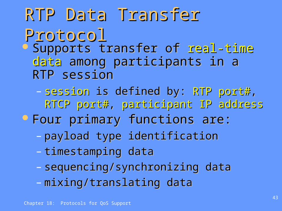
RTP Data Transfer ProtocolRTP Data Transfer ProtocolSupports transfer of Supports transfer of real-time datareal-time data
among participants in a RTP sessionamong participants in a RTP session– sessionsession is defined by: is defined by: RTP port#RTP port#, , RTCP RTCP
port#port#, , participant IP addressparticipant IP addressFour primary functions are:Four primary functions are:
– payload type identificationpayload type identification– timestamping datatimestamping data– sequencing/synchronizing datasequencing/synchronizing data– mixing/translating datamixing/translating data

Chapter 18: Protocols for QoS Support44
RTP Data Transfer ProtocolRTP Data Transfer Protocol Each RTP data unit must include:Each RTP data unit must include:
– source identifiers (who generated data)source identifiers (who generated data)– timestamp (when data was generated)timestamp (when data was generated)– sequence number (order of data in a flow)sequence number (order of data in a flow)– payload format (type of data)payload format (type of data)
RTP relaysRTP relays– mixermixer: combines data from multiple : combines data from multiple
sources and creates new single data sources and creates new single data signalsignal
– translatortranslator: converts input and resends in : converts input and resends in new format, or replicates for unicast new format, or replicates for unicast destinationsdestinations

Chapter 18: Protocols for QoS Support45
RTP Mixers & TranslatorsRTP Mixers & Translators
Mixer
Translator

Chapter 18: Protocols for QoS Support46
RTP Fixed HeaderRTP Fixed Header
Supplied by
a mixer

Chapter 18: Protocols for QoS Support47
Some Standard Payload Some Standard Payload Types Types (see (see RFC 3551RFC 3551))

Chapter 18: Protocols for QoS Support48
RTP Control Protocol (RTCP)RTP Control Protocol (RTCP) Provides Provides control information and feedbackcontrol information and feedback
between session participants between session participants Each participant in an RTP session Each participant in an RTP session
periodicallyperiodically issues an RTCP packet issues an RTCP packet Uses same underlying transport as RTP Uses same underlying transport as RTP
(usually (usually UDPUDP)) RTCP port # = RTP session port # +1RTCP port # = RTP session port # +1 Provides Provides four key functionsfour key functions for real-time for real-time
traffic management (per RFC 1889)traffic management (per RFC 1889)– QoS and congestion controlQoS and congestion control– Source identificationSource identification– Session size estimation and scalingSession size estimation and scaling– Session controlSession control

Chapter 18: Protocols for QoS Support49
RTCP OperationRTCP Operation Protocol specifies report packets exchanged Protocol specifies report packets exchanged
between sources and destinations in real-time between sources and destinations in real-time flows (max. one every 5 secs, limit to 5% flows (max. one every 5 secs, limit to 5% session traffic)session traffic)
Five report types are defined: Sender (SR), Five report types are defined: Sender (SR), Receiver(RR), Goodbye (BYE), Source Receiver(RR), Goodbye (BYE), Source Description (SDES) and Application specificDescription (SDES) and Application specific
SR and RR reports contain statistics such as the SR and RR reports contain statistics such as the number of packets sent, number of packets sent, number of packets lost, number of packets lost, inter-arrival jitter, etc. inter-arrival jitter, etc.
Used to modify sender(s) Used to modify sender(s) transmissions and for transmissions and for diagnostics purposesdiagnostics purposes

Chapter 18: Protocols for QoS Support50
RTCP Bandwidth ScalingRTCP Bandwidth Scaling RTCP attempts to RTCP attempts to
limit its traffic to 5% limit its traffic to 5% of the session of the session bandwidth.bandwidth.
ExampleExample Suppose one sender, Suppose one sender,
sending video at a sending video at a rate of 2 Mbps. Then rate of 2 Mbps. Then RTCP attempts to RTCP attempts to limit its traffic to 100 limit its traffic to 100 Kbps (5% of 2 Mbps) Kbps (5% of 2 Mbps)
RTCP gives 75% of RTCP gives 75% of this rate to the this rate to the receivers; remaining receivers; remaining 25% to the sender25% to the sender
The 75 kbps is equally The 75 kbps is equally shared among shared among receivers: receivers: – With R receivers, With R receivers,
each receiver gets to each receiver gets to send RTCP traffic at send RTCP traffic at 75/R kbps. 75/R kbps.
Sender gets to send Sender gets to send RTCP traffic at 25 kbps. RTCP traffic at 25 kbps.
Participant determines Participant determines RTCP packet RTCP packet transmission period by transmission period by calculating avg RTCP calculating avg RTCP packet size (across the packet size (across the entire session) and entire session) and dividing by allocated dividing by allocated rate. rate.

Chapter 18: Protocols for QoS Support51
RTCP FormatsRTCP Formats
Sender Report
Receiver Report
Application-defined Packet
RTCP BYE
Source Description

Chapter 18: Protocols for QoS Support52
SDES TypesSDES Types