1 cabling utp and fiber cabling. 2 structured cabling infrastructure mounted and permanent allows...
TRANSCRIPT

1
Cabling
UTP AND FIBER CABLING

2
Structured Cabling InfrastructureMounted and permanent
Allows patching
Comfort that infrastructure is OK
Components:Information Outlet with Face PlatePatch PanelUTP CablePatch Cord
Cabling

3
Fiber Optic Cabling Infrastructure
Components:Fiber Cable Fiber PigtailFiber ConnectorsLIUCouplerFiber Patch Cord
Cabling

4
Fiber Optic Installation – Outside Plant
Cabling

5
QUESTIONS?

6
Campus LAN Technology OptionsEthernet
Fast Ethernet
Gigabit Ethernet
10 Gig Ethernet
WLAN
Campus Networks

7
Campus Network Architecture
Campus Network
Internet
Server Farm
Backbone Switch
Access Switch
Distribution Switch
RouterFirewall

8
Campus Network ArchitectureUses Three Tier Switching Architecture (Popularly known as Cisco’s Switching Architecture)Backbone Switch
Layer 3/4 Chassis based switchMultiple 100Fx or 1000SX/LX or 10GLX/LH ports for connectivity to Distribution switchesMultiple 10/100/1000 ports for connectivity to Servers
Distribution SwitchLayer 2/3 Managed Fixed configuration switch1/2 100Fx or 1000Sx/Lx or 10GLX/LH ports for connectivity to the Backbone switchMultiple 10/100 or 10/100/1000 ports for connectivity to the Access switches
Access SwitchLayer2 Managed/Unmanaged Fixed configuration switchMultiple 10/100 or 10/100/1000 ports for desktop connectivity
Campus Network

9
802.11 Wireless LAN
Provides network connectivity over wireless media
An Access Point (AP) is installed to act as Bridge between Wireless and Wired Network
The AP is connected to wired network and is equipped with antennae to provide wireless connectivity
LAN Technologies
Network connectivity
to the legacy
wired LAN
Desktop with PCI 802.11 LAN card
Laptop with PCMCIA 802.11 LAN card
Access Point
10
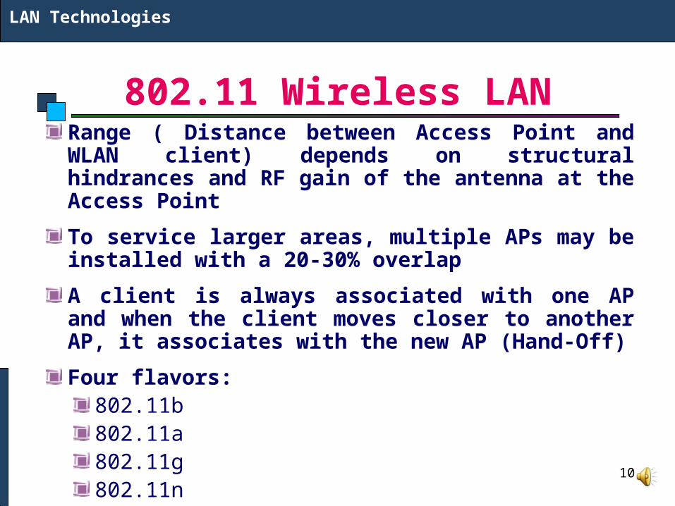
802.11 Wireless LANRange ( Distance between Access Point and WLAN client) depends on structural hindrances and RF gain of the antenna at the Access Point
To service larger areas, multiple APs may be installed with a 20-30% overlap
A client is always associated with one AP and when the client moves closer to another AP, it associates with the new AP (Hand-Off)
Four flavors:802.11b802.11a802.11g802.11n
LAN Technologies

11
QUESTIONS?

12
Residential Networks: Dial-upUses POTS (Plain Old Telephone System)
Provides a low cost need based access.
Bandwidth 33.6 /56 Kbps.
On the Customer End: Modem is connected to a Telephone LineOn the Service Provider End: Remote Access Server (RAS) is connected to Telephone Lines (33.6 Kbps connectivity) or E1/R2 Line (56 Kbps connectivity)RAS provide dialin connectivity, authentication and metering.Achievable bandwidth depends on the line quality.
MAN Technologies
RAS

13
Residential Networks: DSLDigital Subscriber Line (DSL) uses the Ordinary Telephone line and is an always-on technology. This means there is no need to dial up each time to connect to the Internet.
Because DSL is highly dependent upon noise levels, a subscriber cannot be any more than 5.5 kilometers (2-3 miles) from the DSL Exchange
Service can be symmetric, in which downstream and upstream speeds are identical, or asymmetric in which downstream speed is faster than upstream speed.
DSL comes in several varieties:Asymmetric DSL (ADSL)High Data Rate DSL (HDSL) Symmetric DSL (SDSL) Very High Data Rate DSL (VDSL)
MAN Technologies

14
Residential Broadband: ADSL
MAN Technologies

15
Residential Broadband: Mobile Wireless
MAN Technologies
Use CDMA (128 Kbps) or GSM GPRS (384 Kbps) Mobile Wireless or 3G (2 Mbps)

16
Enterprise WAN Network
Enterprise Network

17
Enterprise WAN Network
Enterprise Network

18
Enterprise WAN Network
Enterprise Network
Server Farm
Service Provider Network
All the locations are connected through a Service Provider Networkover MPLS Backbone
Branch Office
Branch Office
Branch Office
Corporate Head Office

19
QUESTIONS?

20
TCP/IP Model
TCP/IP Model
Application LayerApplication programs using the network
Transport Layer (TCP/UDP)Management of end-to-end message transmission,
error detection and error correction
Network Layer (IP)Handling of datagrams : routing and congestion
Data Link LayerManagement of cost effective and reliable data delivery,
access to physical networks
Physical LayerPhysical Media

21
IP as a Routed ProtocolIP is a connectionless, unreliable, best-effort delivery protocol.
IP accepts whatever data is passed down to it from the upper layers and forwards the data in the form of IP Packets.
All the nodes are identified using an IP address.
Packets are delivered from the source to the destination using IP address
Internet Protocol

22
Packet Propagation
Internet Protocol

23
IP AddressIP address is for the INTERFACE of a host. Multiple interfaces mean multiple IP addresses, i.e., routers.
32 bit IP address in dotted-decimal notation for ease of reading, i.e., 193.140.195.66
Address 0.0.0.0, 127.0.0.1 and 255.255.255.255 carries special meaning.
IP address is divided into a network number and a host number.
Also bits in Network or Host Address cannot be all 0 or 1.
Internet Protocol

24
IP Configuration of an Interface
Internet Protocol
Static DHCP

25
IPv6Internet Protocol Version 4 is the most popular protocol in use today, although there are some questions about its capability to serve the Internet community much longer. IPv4 was finished in the 1970s and has started to show its age. The main issue surrounding IPv4 is addressing—or, the lack of addressing—because many experts believe that we are nearly out of the four billion addresses available in IPv4. Although this seems like a very large number of addresses, multiple large blocks are given to government agencies and large organizations. IPv6 could be the solution to many problems posed by IPv4
Internet Protocol

26
IPv6IPv6 uses 128 bit address instead of 32 bit address.
The IPv6 addresses are being distributed and are supposed to be used based on geographical location.
Internet Protocol

27
TCP/UDPTransport Layer Protocol
TCP is connection Oriented (uses checksum and acknowledgment)
UDP is Connectionless
Both use the concept of Connection Port Number (16 Bit Source Port Number and Destination Port Number)
Standard Applications have standard Port Numbers (Email 25, Telnet 23, FTP 20 & 21, SSH 22)
TCP/UDP

28
QUESTIONS?