(1 blatt = 0,080 mm für eberwe in digitaldruck bei 80 g/m ... · pdf filepowerware ®,...
TRANSCRIPT

SmartWire-Darwin Units
Moeller addresses worldwide:www.moeller.net/address
E-Mail: [email protected]: www.moeller.net
Issued by: Moeller GmbHHein-Moeller-Str. 7–11D-53115 Bonn
© 2002 by Moeller GmbHSubject to alterationAWB2723-1613en xx/xx/XBS 02/09Printed in the Federal Republic of Germany (0x/02)Article No.: xxxxxx
4 *patpks#nycmyn*
Eaton's electrical business is a global leader in electrical control, power distribution, uninterruptible power supply and industrial automation products and services. Eaton's global electrical brands, including Cutler-Hammer®, MGE Office Protection Systems™, Powerware®, Holec®, MEM®, Santak and Moeller, provide customer-driven PowerChain Management® solutions to serve the power system needs of the industrial, institutional, government, utility, commercial, residential, IT, mission critical and OEM markets worldwide.www.eaton.com
Rü
cken
text
Hardware and Engineering
02/09 AWB2723-1613en
A
Rückenbreite bis 10 mm (1 Blatt = 0,106 mm für XBS Digitaldruck)(1 Blatt = 0,080 mm für Eberwein Digitaldruck bei 80 g/m2)

All brand and product names are trademarks or registered trademarks of the owner concerned.
1st published 2009, edition date 02/09
© 2009 by Moeller GmbH, 53105 Bonn
Author: Heribert Einwag, Mike EdelmannEditor: René WiegandTranslator: globaldocs GmbH
All rights reserved, including those of the translation.
No part of this manual may be reproduced in any form (printed, photocopy, microfilm or any other process) or processed, duplicated or distributed by means of electronic systems without written permission of Moeller GmbH, Bonn.
Subject to alteration without notice.
Rückenbreite festlegen! (1 Blatt = 0,106 mm, gilt nur für XBS)(1 Blatt = 0,080 mm für Eberwein Digitaldruck bei 80 g/m2)

Moe
llerG
mbH
Safe
ty in
stru
ctio
nsDanger! Dangerous electrical voltage!
Before commencing the installation
• Disconnect the power supply of the device.
• Ensure that devices cannot be accidentally restarted.
• Verify isolation from the supply.
• Earth and short circuit.
• Cover or enclose neighbouring units that are live.
• Follow the engineering instructions (AWA) of the device concerned.
• Only suitably qualified personnel in accordance with EN 50110-1/-2 (VDE 0105 Part 100) may work on this device/system.
• Before installation and before touching the device ensure that you are free of electrostatic charge.
• The functional earth (FE) must be connected to the protective earth (PE) or to the potential equalisation. The system installer is responsible for implementing this connection.
• Connecting cables and signal lines should be installed so that inductive or capacitive interference does not impair the automation functions.
• Install automation devices and related operating elements in such a way that they are well protected against unintentional operation.
• Suitable safety hardware and software measures should be implemented for the I/O interface so that a line or wire breakage on the signal side does not result in undefined states in the automation devices.
• Ensure a reliable electrical isolation of the low voltage for the 24 volt supply. Only use power supply units complying with IEC 60364-4-41 (VDE 0100 Part 410) or HD 384.4.41 S2.
• Deviations of the mains voltage from the rated value must not exceed the tolerance limits given in the specifications, otherwise this may cause malfunction and dangerous operation.
• Emergency stop devices complying with IEC/EN 60204-1 must be effective in all operating modes of the automation devices. Unlatching the emergency-stop devices must not cause restart.
• Devices that are designed for mounting in housings or control cabinets must only be operated and controlled after they have been installed with the housing closed. Desktop or portable units must only be operated and controlled in enclosed housings.
I

II
• Measures should be taken to ensure the proper restart of programs interrupted after a voltage dip or failure. This should not cause dangerous operating states even for a short time. If necessary, emergency-stop devices should be implemented.
• Wherever faults in the automation system may cause damage to persons or property, external measures must be implemented to ensure a safe operating state in the event of a fault or malfunction (for example, by means of separate limit switches, mechanical interlocks etc.).

02/09 AWB2723-1613en
Contents
About this Manual 5Overview of the SmartWire-Darwin System 5Additional device manuals 5Target group 5Reading conventions 6
1 Power ModuleEU5C-SWD-PF1-1,EU5C-SWD-PF2-1 7 Introduction 7EU5C-SWD-PF1-1 7– Layout 7– Engineering 8– Installation 9– Diagnostics 10EU5C-SWD-PF2-1 11– Layout 11– Engineering 12– Installation 13– Diagnostics 14
2 I/O ModulesEU5E-SWD-8DXEU5E-SWD-4D4DEU5E-SWD-4D2R 15 Introduction 15Layout 16– EU5E-SWD-8DX 16– EU5E-SWD-4D4D 17– EU5E-SWD-4D2R 18Engineering 19Installation 20Commissioning 22Exchange of Modules 22Device status 23Programming 24
1

2
02/09 AWB2723-1613en
– EU5E-SWD-8DX 24– EU5E-SWD-4D4D 26– EU5E-SWD-4D2R 28
3 Switching on ContactorsDIL-SWD-32-001, DIL-SWD-32-002 31 Introduction 31Layout 31Engineering 33– DOL Starters 36– Reversing starters 39– Safety-related applications 44– Feedback circuit 47– Measures for higher safety categories 47– Application for EN ISO13849-1 and EN 62061 50– Applications in North America 50Installation 52Commissioning 54Exchange of Modules 55Device status 55Programming 56– DIL-SWD-32-001 56– DIL-SWD-32-002 58
4 Control Circuit DevicesM22-SWD… 61 Introduction 61M22-SWD front fixing 62– Layout 62Engineering 63Installation 67Commissioning 68Exchange of Modules 68Device status 69Programming 70– M22-SWD-K11 70– M22-SWD-K22 72– M22-SWD-LED-(W/B/G/R) 74– M22-SWD-K11LED-(W/B/G/R) 76

Contents02/09 AWB2723-1613en
– M22-SWD-K22LED-(W/B/G/R) 78– M22-SWD base fixing 80Layout 80Engineering 81– Connection of the round cable
to the cable gland 81– Connection of the round cable
via a plug connection 82Installation 87Commissioning 90Exchange of Modules 90Device status 91Programming 92– M22-SWD-KC11 92– M22-SWD-KC22 94– M22-SWD-LEDC-(W/B/G/R) 96– M22-SWD-K11LEDC-(W/B/G/R) 98– M22-SWD-K22LEDC-(W/B/G/R) 100
Appendix 103Maximum current consumption 103– Current consumption 15-V-SWD
supply voltage 103– Power consumption/current
consumption 24-V-SWD control voltage UAUX 104Technical data 105– Gateways, Power Feeder Modules 105– I/O modules 110– M22-SWD connections 114– Network termination, switch cabinet
leadthroughs 118– Enclosure bushings plug, socket 120– Coupling, plug 121– DIL contactor modules 122
Index 125
3

4
02/09 AWB2723-1613en

02/09 AWB2723-1613en
About this Manual
Overview of the SmartWire-Darwin System
The SmartWire-Darwin connection system is an intelligent bus system and makes possible the reliable and easy connection of switching devices, control circuit devices and I/O components with overriding bus systems. The components that are connected with the SmartWire-Darwin system are linked, e.g. to PROFIBUS-DP or CANopen communication networks via gateways.
Up to 99 slaves can be connected to form a network by means of the SmartWire-Darwin system. The slaves can be either SmartWire-Darwin modules for DILM, SmartWire-Darwin I/O modules or SmartWire-Darwin RMQ modules.
The electrical connection is effected via a special 8-pole connecting lead and the relevant plugs.
Additional device manuals Further information concerning the SmartWire-Darwin can be found in the manuals:
• AWB2723-1612 "SmartWire-Darwin Gateways“• AWB2723-1617 “SmartWire-Darwin System Manual”• AWB2725-1425 “XIOC Signal Modules (DP Diagnostics)”
The manuals are available for download on the Internet as PDF files. They can be quickly located athttp://www.moeller.net/de/support by entering the document number as the search term.
Target group This manual is intended for automation technicians and engineers. Detailed knowledge of the field bus used is presumed. In addition you should be familiar with the handling of the SmartWire-Darwin system.
5
About this Manual
6
02/09 AWB2723-1613en
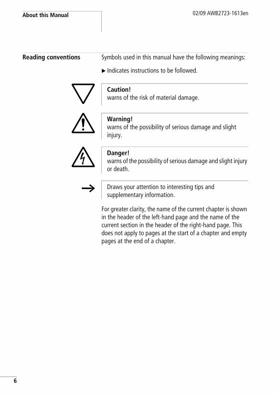
Reading conventions Symbols used in this manual have the following meanings:
X Indicates instructions to be followed.
For greater clarity, the name of the current chapter is shown in the header of the left-hand page and the name of the current section in the header of the right-hand page. This does not apply to pages at the start of a chapter and empty pages at the end of a chapter.
h Caution!warns of the risk of material damage.
i Warning!warns of the possibility of serious damage and slight injury.
j Danger!warns of the possibility of serious damage and slight injury or death.
h Draws your attention to interesting tips and supplementary information.

02/09 AWB2723-1613en
1 Power ModuleEU5C-SWD-PF1-1,EU5C-SWD-PF2-1
Introduction The SmartWire-Darwin power modules EU5C-SWD-PF1-1 and EU5C-SWD-PF2-1 are for the purpose of looping back the slave power supply in the SmartWire-Darwin network.
EU5C-SWD-PF1-1 Layout
Connections/power supply
Figure 1: Connections of the EU5C-SWD-PF1-1 module
a Contactors power supply AUXb SWD Outc SWD In
a
b
c
7

Power Module EU5C-SWD-PF1-1, EU5C-SWD-PF2-1
8
02/09 AWB2723-1613en
The SmartWire-Darwin power module EU5C-SWD-PF1 loops the 24 V DC contactor voltage back into the SmartWire-Darwin cable.
The looped back 24 V DC voltage is not electrically isolated from the 24 V DC supply voltage (AUX) of the module. There is voltage reversal and EMC protection.
Voltage dips are not buffered.
The subassembly does not need a diagnostics LED and no diagnostics information of its own is sent on the SmartWire-Darwin network. A fault in the 24 V supply voltage is therefore ascertainable only via the missing voltage of the downstream contactors.
Engineering
Area of application of the SmartWire-Darwin power module EU5C-SWD-PF1-1• The supply for the contactors installed in the SmartWire
Darwin network is no longer sufficient (power consumption of the contactors > 72 W / 3 A).
• A selective emergency shutdown of individual contactor groups or motor starter groups is required (a section "Safety-related applications", page 44)
h With a SmartWire Darwin power module a second connection for the contactor coil control voltage can be made at another position in the SmartWire Darwin network.
EU5C-SWD-PF1-102/09 AWB2723-1613en
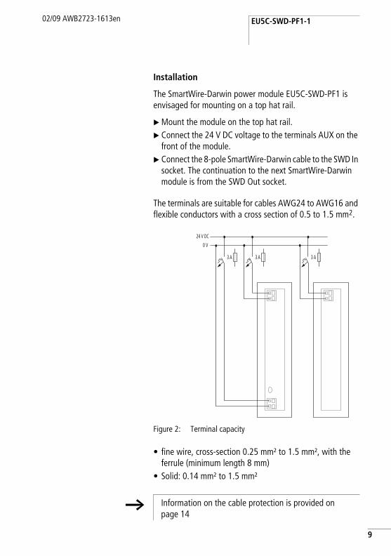
Installation
The SmartWire-Darwin power module EU5C-SWD-PF1 is envisaged for mounting on a top hat rail.
X Mount the module on the top hat rail.X Connect the 24 V DC voltage to the terminals AUX on the
front of the module.X Connect the 8-pole SmartWire-Darwin cable to the SWD In
socket. The continuation to the next SmartWire-Darwin module is from the SWD Out socket.
The terminals are suitable for cables AWG24 to AWG16 and flexible conductors with a cross section of 0.5 to 1.5 mm2.
Figure 2: Terminal capacity
• fine wire, cross-section 0.25 mm² to 1.5 mm², with the ferrule (minimum length 8 mm)
• Solid: 0.14 mm² to 1.5 mm²
3 A3 A 3 A
24 V DC
0 V
h Information on the cable protection is provided on page 14
9

Power Module EU5C-SWD-PF1-1, EU5C-SWD-PF2-1
10
02/09 AWB2723-1613en
Diagnostics
The device does not report a diagnosis

EU5C-SWD-PF2-102/09 AWB2723-1613en
EU5C-SWD-PF2-1 Layout
Connections/power supply
Figure 3: Connections of the EU5C-SWD-PF2-1 module
a SmartWire Darwin slave supplyb POW slave supply displayc Contactors power supply AUXd SWD Oute SWD In
The SmartWire-Darwin power module EU5C-SWD-PF2 loops the 24 V DC contactor voltage and the 15 V slave supply back into the SmartWire-Darwin cable.
The SmartWire-Darwin cable is looped from the SmartWire-Darwin in-connection through to the SmartWire-Darwin out-connection. Only the 24 V DC contactor voltage and the 15 V DC slave supply are isolated and looped back in via the SmartWire-Darwin out-connection.
d
c
b
a
e
11

Power Module EU5C-SWD-PF1-1, EU5C-SWD-PF2-1
12
02/09 AWB2723-1613en
The 24 V DC contactor supply is not electrically isolated from the 24 V DC supply of the power module, i.e. the 24 V DC voltage is looped back in. There is voltage reversal and EMC protection. Voltage dips are not buffered.
The 15 V DC slave supply is electrically isolated from the 24 V DC contactor voltage. Voltage dips are buffered up to at least 10 ms. There is voltage reversal and EMC protection.
The subassembly contains an LED for indication of the 15 V DC slave supply.
The 24 V DC contactor voltage that is looped back in is not electrically isolated from the 24 V D supply voltage (AUX) of the module. There is voltage reversal and EMC protection.
Engineering
Area of application of the SmartWire-Darwin power module EU5C-SWD-PF2-1• The supply for the slaves installed in the SmartWire
Darwin network is no longer sufficient (power consumption > 0.7 A).
• The supply for the contactors installed in the SmartWire Darwin network is no longer sufficient (power consumption of the contactors > 72 W / 3 A).
• A selective emergency shutdown of individual contactor groups or motor starter groups is required (a section "Safety-related applications", page 44).
h With a SmartWire Darwin power module a second connection for the contactor coil control voltage can be made at another position in the SmartWire Darwin network.
EU5C-SWD-PF2-102/09 AWB2723-1613en
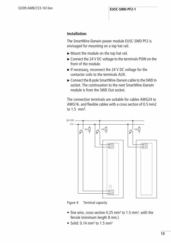
Installation
The SmartWire-Darwin power module EUSC-SWD PF2 is envisaged for mounting on a top hat rail.
X Mount the module on the top hat rail.X Connect the 24 V DC voltage to the terminals POW on the
front of the module.X If necessary, reconnect the 24 V DC voltage for the
contactor coils to the terminals AUX.X Connect the 8-pole SmartWire-Darwin cable to the SWD In
socket. The continuation to the next SmartWire-Darwin module is from the SWD Out socket.
The connection terminals are suitable for cables AWG24 to AWG16. and flexible cables with a cross section of 0.5 mm2 to 1.5 mm2.
Figure 4: Terminal capacity
• fine wire, cross-section 0.25 mm² to 1.5 mm², with the ferrule (minimum length 8 mm.)
• Solid: 0.14 mm² to 1.5 mm²
3 A3 A 3 A
24 V DC
0 V
13

Power Module EU5C-SWD-PF1-1, EU5C-SWD-PF2-1
14
02/09 AWB2723-1613en
Cable protectionX On the SWD gateway connect the POW and AUX supply
voltages via separate miniature circuit-breakers or fuses:• Miniature circuit-breaker 24 V DC for POW
– Line protection in accordance with DIN VDE 0641 Part 11,IEC/EN 60898:
– Miniature circuit-breaker 24 V DC rated operational current 3 A;tripping characteristics C or
– Fuse 3 A, utilisation class gL/gG– Cable protection for cable AWG 24 in accordance with
UL 508 and CSA-22.2 no. 14:– Miniature circuit-breaker 24 V DC rated operational
current 2 A; tripping characteristics C or– Fuse 2 A
• Miniature circuit-breaker 24 V DC for AUX– Cable protection in accordance with DIN VDE 0641
Part 11,IEC/EN 60898:
– Miniature circuit-breaker 24 V DC rated operational current 3 A; tripping characteristic Z or
– Fuse 3 A, utilisation class gL/gG– Cable protection for cable AWG 24 in accordance with
UL 508 and CSA-22.2 no. 14:– Miniature circuit-breaker 24 V DC rated operational
current 2 A; tripping characteristics Z or– Fuse 2 A
Diagnostics
The device does not report a diagnosis

02/09 AWB2723-1613en
2 I/O ModulesEU5E-SWD-8DXEU5E-SWD-4D4DEU5E-SWD-4D2R
Introduction The SmartWire-Darwin input/output modules (abbreviated: I/O modules) are used for the connection of other sensor and actuator devices. These can be, for example, auxiliary switches of additional switching devices that have integrated SmartWire-Darwin technology. The modules are placed in the immediate vicinity of the sensors/actuators, due to which the remaining wiring is markedly reduced. Diverse modules with digital inputs and outputs in the form of transistors and relays are available.
15

I/O Modules EU5E-SWD-8DX EU5E-SWD-4D4D EU5E-SWD-4D2R
16
02/09 AWB2723-1613en
Layout EU5E-SWD-8DX
Figure 5: Connections of the modules EU5E-SWD-8DX
a SmartWire-Darwin cable with external device plugb SmartWire-Darwin status LEDc Status LEDs of the inputsd I0 - I7 (inputs)e 0-V connection
The SmartWire-Darwin I/O module EU5E-SWD-8DX provides eight digital inputs I0 to I7 with the help of which diverse sensors can be integrated into the SmartWire-Darwin network.
The status of the inputs is indicated with the help of LEDs. The network status of the module is also signalled via an LED.
a
b
c
d
e

Layout02/09 AWB2723-1613en
EU5E-SWD-4D4D
Figure 6: Connections of the modules EU5E-SWD-4D4D
a SmartWire-Darwin cable with external device plug
b SmartWire-Darwin diagnostics LEDc Status LEDs of the inputs and outputsd I0 - I3 (inputs)e Q0 - Q3 (outputs)f 0-V- 24-V connection
The SmartWire-Darwin I/O module EU5E-SWD-4D4D provides four digital inputs I0 to I3 and four digital outputs Q0 to Q3. Diverse sensors can be integrated into the SmartWire-Darwin network via the four inputs. The four digital short-circuit proof outputs are used to drive actuators.
The status of the inputs and outputs is indicated with the help of LEDs. The network status of the module is also signalled via an LED.
a
b
c
d
e
17

I/O Modules EU5E-SWD-8DX EU5E-SWD-4D4D EU5E-SWD-4D2R
18
02/09 AWB2723-1613en
EU5E-SWD-4D2R
Figure 7: Connections of the modules EU5E-SWD-4D2R
a SmartWire-Darwin cable with external device plug
b SmartWire-Darwin diagnostics LEDc Status LEDs of the inputs and outputsd I0 - I3 (inputs)e Q0, Q1 (outputs)f 0-V connection
The SmartWire-Darwin I/O module EU5E-SWD-4D2R provides four digital inputs and two digital relay outputs. Diverse sensors can be integrated via the four inputs. Both digital relay outputs Q0 and Q1 are used for the activation of actuators up to a rated current of AC 15, 3 A at 250 V.
The status of the inputs and outputs is indicated with the help of LEDs. The network status of the module is also signalled via an LED.
a
b
c
d
e

Engineering02/09 AWB2723-1613en
Engineering The SmartWire-Darwin input/output modules are used for the connection of other sensor and actuator devices without integrated SmartWire-Darwin technology. The modules are placed in the immediate vicinity of the sensors or actuators, which markedly reduces the remaining wiring. Three different modules are available.
EU5E-SWD-8DX• eight digital inputs 24 V DC
EU5E-SWD-4D4D• four digital inputs 24 V DC• four digital outputs 24 V DC, 0.5 A
EU5E-SWD-4D2R• four digital inputs 24 V DC• two digital relay outputs 3 A
Via the two relay outputs Q0 and Q1 contactors can be activated with greater switching power, for example.
h The I/O modules draw their energy for communication electronics, activation of the LEDs and of the I/O modules from the SmartWire-Darwin network supply. Please take into consideration the total current consumption of your SmartWire-Darwin network and, if necessary, plan for an additional feeder module EU5C-SWD-PF2-1.
h For data for the current requirement please refer to the table in the appendix on page 103.
19

I/O Modules EU5E-SWD-8DX EU5E-SWD-4D4D EU5E-SWD-4D2R
20
02/09 AWB2723-1613en
Installation The SmartWire-Darwin input/output modules are envisaged for top hat mounting.
X Mount the module on the top hat rail.
Figure 8: Mounting on top-hat rail
X Connect the 8-pole SmartWire-Darwin cable via the SWD socket to the top side of the device.
EU5E-SWD-8DXX Connect the sensors to the corresponding input I0 to I7.X Connect the reference potential 0 V DC to connection 0 V.
EU5E-SWD-4D4DX Connect the sensors to the corresponding input I0 to I3.X Connect the reference potential 0 V DC to connection 0 V.X Connect the actuators to the corresponding output Q0 to
Q3.X Connect the 24 V DC supply voltage for the outputs to the
24 V terminal.
1
2
Installation02/09 AWB2723-1613en
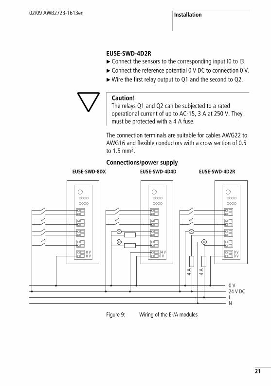
EU5E-SWD-4D2RX Connect the sensors to the corresponding input I0 to I3.X Connect the reference potential 0 V DC to connection 0 V.X Wire the first relay output to Q1 and the second to Q2.
The connection terminals are suitable for cables AWG22 to AWG16 and flexible conductors with a cross section of 0.5 to 1.5 mm2.
Connections/power supply
Figure 9: Wiring of the E-/A modules
h Caution!The relays Q1 and Q2 can be subjected to a rated operational current of up to AC-15, 3 A at 250 V. They must be protected with a 4 A fuse.
EU5E-SWD-8DX EU5E-SWD-4D4D EU5E-SWD-4D2R
0 V24 V DC
0 V0 V
0 V0 V
24 V0 V
LN
4 A
4 A
21
I/O Modules EU5E-SWD-8DX EU5E-SWD-4D4D EU5E-SWD-4D2R
22
02/09 AWB2723-1613en
Terminal capacity• fine wire, cross-section 0.25 mm² to 1.5 mm², with ferrule
(minimum length 8 mm.)• Solid: 0.14 mm² to 1.5 mm²
Commissioning The automatic addressing of all slaves in the SmartWire-Darwin network is performed via the gateway (actuation of the configuration pushbutton on the gateway) during initial operation. During the addressing process the SmartWire-Darwin diagnostics LED flashes. Once the addressing process is completed, the LED indicates a green continuous light.
Exchange of Modules
After replacement of the modules and connection of the voltage the configuration button must be pressed. The new module is assigned an address by this means.
h Caution!Replacement of the SmartWire-Darwin input/output modules is not permitted until the entire SmartWire-Darwin system has been switched off.
h Caution!The order of the SmartWire-Darwin units must not be altered.

Device status02/09 AWB2723-1613en
Device status The individual SmartWire-Darwin slaves indicate their device status with the help of the LED diagnostics.
Table 1: Diagnostic messages of the SmartWire-Darwin status LED
Designation Colour State Message
SWD Green continuous light Device is operating fault-free.
flashing (1 Hz) • addressing process in progress– after gateway power On– after actuation of the
configuration button on the gateway
• slave not in current configuration• invalid type
flashing (3 Hz) Device reports a diagnostics (see section “Programming”, sub-point “ Diagnostics”)
23

I/O Modules EU5E-SWD-8DX EU5E-SWD-4D4D EU5E-SWD-4D2R
24
02/09 AWB2723-1613en
Programming EU5E-SWD-8DX
The module has two input bytes at its disposal.
InputsByte 0:
Byte 1:
7 6 5 4 3 2 1 0
- P - F - - - -
Bit Designation Meaning
0 not used -
1 not used -
2 not used -
3 not used -
4 F = Failure 0: No diagnostic alarm
5 not used -
6 P = modules present 0: Module not available1: Module available
7 not used -
7 6 5 4 3 2 1 0
I7 I6 I5 I4 I3 I2 I1 I0
Bit Designation Meaning
0 I0 Status input I0
1 I1 Status input I1
2 I2 Status input I2
3 I3 Status input I3
4 I4 Status input I4

Programming02/09 AWB2723-1613en
DiagnosticsThe module does not report a diagnosis.
5 I5 Status input I5
6 I6 Status input I6
7 I7 Status input I7
Bit Designation Meaning
25

I/O Modules EU5E-SWD-8DX EU5E-SWD-4D4D EU5E-SWD-4D2R
26
02/09 AWB2723-1613en
EU5E-SWD-4D4D
The module has two input bytes and one output byte at its disposal.
InputsByte 0:
Byte 1:
7 6 5 4 3 2 1 0
P F
Bit Designation Meaning
0 not used -
1 not used -
2 not used -
3 not used -
4 F = Failure 0: No diagnostic alarm1: Module diagnostics present
5 not used -
6 P = modules present 0: Module not available1: Module available
7 not used -
7 6 5 4 3 2 1 0
- - - - I3 I2 I1 I0
Bit Designation Meaning
0 I0 Status input I0
1 I1 Status input I1
2 I2 Status input I2
3 I3 Status input I3
4 not used -

Programming02/09 AWB2723-1613en
OutputsByte 0:
DiagnosticsIn case of diagnosis the module reports the following error cause (bit 4 in input byte 0 is set):
5 not used -
6 not used -
7 not used -
Bit Designation Meaning
7 6 5 4 3 2 1 0
- - - - Q3 Q2 Q1 Q0
Bit Designation Meaning
0 Q0 Actuation output Q0
1 Q1 Actuation output Q1
2 Q2 Actuation output Q2
3 Q3 Actuation output Q3
4 not used -
5 not used -
6 not used -
7 not used -
Value Meaning
0x13 Short circuit/overload at one output at least
27

I/O Modules EU5E-SWD-8DX EU5E-SWD-4D4D EU5E-SWD-4D2R
28
02/09 AWB2723-1613en
EU5E-SWD-4D2R
The module has two input bytes and one output byte at its disposal.
InputsByte 0:
Byte 1:
7 6 5 4 3 2 1 0
- P - F - - - -
Bit Designation Meaning
0 not used -
1 not used -
2 not used -
3 not used -
4 F = Failure 0: No diagnostic alarm
5 not used -
6 P = Modules present 0: Module not available1: Module available
7 not used -
7 6 5 4 3 2 1 0
I3 I2 I1 I0
Bit Designation Meaning
0 I0 Status input I0
1 I1 Status input I1
2 I2 Status input I2
3 I3 Status input I3
4 not used

Programming02/09 AWB2723-1613en
OutputsByte 0:
DiagnosticsThe module does not report a diagnosis.
5 not used
6 not used
7 not used
Bit Designation Meaning
7 6 5 4 3 2 1 0
- - - - - - Q1 Q0
Bit Designation Meaning
0 Q0 Actuation output Q0
1 Q1 Actuation output Q1
2 not used -
3 not used -
4 not used -
5 not used -
6 not used -
7 not used -
29

30
02/09 AWB2723-1613en

3 Switching on ContactorsDIL-SWD-32-001, DIL-SWD-32-002
Introduction The SmartWire-Darwin modules DIL-SWD-32-001 and DIL-SWD-32-002 for DILM are snapped directly onto either a contactor type DILM 7 to DILM 38, a DILA contactor relay or an MSC motor starter. It is for the purpose of driving a contactor or a motor starter via a programmable logic controller and acquiring the feedback.
Layout The following diagram shows the two modules.
Figure 10: Structure of the SmartWire-Darwin modulesDIL-SWD-32-001 and DIL-SWD-32-002 for DILM
a Connection of SmartWire-Darwin external device plugb Mechanical switching position indicatorc Diagnostics LEDd Catch slider
h Caution!No additional auxiliary switch block can be snapped onto the contactor. The auxiliary switches integrated into the contactor can be used, for example, as safety locking devices.
DIL-SWD-32-001 DIL-SWD-32-002
a
cb
d
g
f
e
h
a
cb
d
g
f
e
h
i
31
Switching on Contactors DIL-SWD-32-001, DIL-SWD-32-002
32
e Connection pinsf Adjusting slide for contactor sizeg Terminal X0-X1-X2h Terminal electrical enable X3-X4i Selector switch 1-0-A
The external device plug with an adapted SmartWire-Darwin connecting cable is connected to the contactor module DIL-SWD via connection a.
The communication status and switching command via the SmartWire-Darwin system are indicated by way of a two-colour diagnostics LED c (a section "Device status", page 55).
As well as the communication signals a 24 V DC supply for the contactor coil is also transmitted via the SmartWire-Darwin connection cable. The integrated electronics transfers the voltage to the connection pins e that are connected to the contactor coils.
The SmartWire module for DILM is connected to the contact bridge of the contactor by way of a ratchet slide d. Feedback on the switching status of the contactor is goes into the field bus.
In addition the status of the connected contactor can be acquired via the switch position indicator b.
Adjustment of the SmartWire-Darwin module for DILM to the respective contactor size is performed via the adjusting slide for the contactor size f.
Engineering
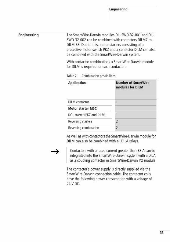
Engineering The SmartWire-Darwin modules DIL-SWD-32-001 and DIL-SWD-32-002 can be combined with contactors DILM7 to DILM 38. Due to this, motor starters consisting of a protective motor switch PKZ and a contactor DILM can also be combined with the SmartWire-Darwin system.
With contactor combinations a SmartWire-Darwin module for DILM is required for each contactor.
Table 2: Combination possibilities
As well as with contactors the SmartWire-Darwin module for DILM can also be combined with all DILA relays.
The contactor´s power supply is directly supplied via the SmartWire-Darwin connection cable. The contactor coils have the following power consumption with a voltage of 24 V DC:
Application Number of SmartWire modules for DILM
DILM contactor 1
Motor starter MSC
DOL starter (PKZ and DILM) 1
Reversing starters 2
Reversing combination 2
h Contactors with a rated current greater than 38 A can be integrated into the SmartWire-Darwin system with a DILA as a coupling contactor or SmartWire-Darwin I/O module.
33

Switching on Contactors DIL-SWD-32-001, DIL-SWD-32-002
34
Table 3: Power consumptions of the contactor coils with a voltage of 24 V DC
Contactor Pick-up power Pick-up current with 24 V DC
Sealing power Holding current with 24 V DC
[W] [mA] [W] [mA]
DIL7 - DIL9 3 125 3 125
DIL12 - DIL15 4.5 188 4.5 188
DIL17 - DIL38 12 500 0.5 21
h Caution!The sum of the pick-up power of the simultaneously tripping contactors and the sum of the holding power of the tripped contactors for each SmartWire-Darwin network must not exceed 72 W. If required, an additional power feeder module (EU5C-SWD-PF1-1, EU5C-SWD-PF-2) must be used (a chapter "Power Module EU5C-SWD-PF1-1, EU5C-SWD-PF2-1")
h The DIL modules draw their energy for the communication electronics and for activation of the LEDs and of the auxiliary switches from the SmartWire-Darwin network supply. Please take into consideration the total current consumption of your SmartWire-Darwin network and, if necessary, plan for an additional feeder module EU5C-SWD-PF2-1.
h For data for the current requirement please refer to the table in the appendix on page 103.

Engineering
Figure 11: Connections of the SmartWire-Darwin module DIL-SWD-32-001 or DIL-SWD-32-002 for DILM
a Connection of SmartWire-Darwin external device plugb Mechanical switching position indicatorc Diagnostics LEDd Catch slidere Connection pinsf Adjusting slide for contactor sizeg Terminal X0-X1-X2h Terminal electrical enable X3-X4i Selector switch 1-0-A
DIL-SWD-32-001 DIL-SWD-32-002
a
cb
d
g
f
e
h
a
cb
d
g
f
e
h
i
35

Switching on Contactors DIL-SWD-32-001, DIL-SWD-32-002
36
DOL Starters
The DOL starter is assembled from a PKZM0 and a contactor DILM7-DILM32. The SmartWire-Darwin module for DILM is mounted on the contactor.
The SmartWire-Darwin module for DILM drives the contactor so that terminals A1-A2 of the contactor must no longer be wired. In addition two feedbacks to the SmartWire-Darwin system take place via the SmartWire-Darwin module for DILM.
The auxiliary contact enable h is connected ex-factory by means of a bridge. If electrical locks are envisaged in the application, the bridge can be removed and a potential-free contact can be connected.
The auxiliary contacts integrated in the contactor can be used, e.g. for safety interlocks.
Two feedback inputs to the programmable logic controller are available at the three-pole terminal of connection g for the potential-free contacts. If required, potential-free auxiliary switch contacts of the protective motor switch PKZ can be connected to these two feedback inputs.
The terminals on the SmartWire-Darwin module for DILM are suitable for cables AWG24 to AWG16 and flexible cables with a cross-section of 0.25 mm2 to 1.5 mm2.
When using core end sleeves it has to be ensured that the sleeve length is at least 8 mm.
j Danger!The auxiliary contact enable must not be used for safety-related controller parts (a section "Safety-related applications", page 44).
h Caution!The connection cables to the potential-free auxiliary switches at connection X0-X1-X2 g for the potential-free contacts and at connection X3-X4 h for the auxiliary contact enable may have a maximum length of 2.8 m.

Engineering
A manual or electrical ON or OFF command for the contactor can take place in addition with the aid of the 1-0-A switch i in the device version DIL-SWD-32-002.
The switch positions are as follows:
• 1 = Contactor ON• 0 = Contactor OFF• A - switching command via SmartWire-Darwin
h Use of the 1-0-A switch for the electrical switching on or off of the contactor is ensured only when the SmartWire-Darwin module for DILM is supplied via the SmartWire-Darwin connecting cable.
37

Switching on Contactors DIL-SWD-32-001, DIL-SWD-32-002
38
Figu
re 1
2:Ci
rcui
t dia
gram
of t
he d
irect
sta
rter
8
Smar
tWire
-Dar
win
L1 L2 L3
-Q11 X1
53
1
53
1
64
2
WV
U
64
2
PE
WV
UPE
PE
M -M1
3 ~
II
I
-Q1
1.21
1.13
1.22
1.14
4.43
4.13
4.44
4.14
-Q1
-Q1
4.43
4.44
1.13
1.14
-Q11
X1X0
X2X3
X4
8
A1 A2
“+”
“I>
”
24 V
0 V
DC

Engineering
Reversing starters
The reversing starters are made up of a PKZM0 and two contactors DILM7 to DILM32. One SmartWire-Darwin module each for DILM is mounted on both contactors.
The SmartWire-Darwin modules for DILM drive the contactors so that the terminals A1-A2 of the contactors need no further wiring, with the exception of the DILM12-XEV bridge. In addition two feedback messages to the system can take place for each SmartWire-Darwin module for DILM.
The auxiliary contact enable h is connected ex-factory by means of a bridge. For the electrical interlocking of the two contactors this bridge is removed and the auxiliary breaker (contacts 21-22) of the other contactor is linked in as a potential-free contact.
The auxiliary contacts integrated in the contactor can be used, e.g. for safety interlocks.
Two feedback inputs for the programmable logic controller are available at the three-pole terminal of connection g for the potential-free contacts. If required, potential-free auxiliary switch contacts of the protective motor switch PKZ can be connected to these two feedback inputs.
j Danger!The auxiliary contact enable h must not be used for safety-related controller parts (a section "Safety-related applications", page 44).
h Caution!The connection cables to the potential-free auxiliary switches at connection X0-X1-X2 g for the potential-free contacts and at connection X3-X4 h for the auxiliary contact enable may have a maximum length of 2.8 m.
39

Switching on Contactors DIL-SWD-32-001, DIL-SWD-32-002
40
The terminals on the SmartWire-Darwin module for DILM are suitable for cables AWG24 to AWG16 and flexible cables with a cross-section of 0.25 mm2 to 1.5 mm2.
When using core end sleeves it has to be ensured that the sleeve length is at least 8 mm.
The following jumpers can be used for wiring reversing starters.
Table 4: Jumpers for reversing starters
In combination with the jumpers DILM12-XEV the circuit fig. 13 should be used. On the other hand, an electrical interlock with wire jumpers should be implemented according to the circuit fig. 14.
A manual or electrical ON or OFF command for the contactor can take place in addition with the aid of the 1-0-A switch in the device version DIL-SWD-32-002.
The switch positions are as follows:
• 1 = Contactor ON• 0 = Contactor OFF• A - switching command via SmartWire-Darwin
h Caution!The wiring sets DILM12-XRL and PKZM0-XRM12 must not be used for the assembly of the reversing starters.
The A2 connection of the contactors must not be bridged.
DILM7 - DILM15 DILM17 - DILM32
L1, L2 and L3 parallel DILM12-XP2 DILM32-XRL
Phase switch L1 and L3, L2 parallel DILM12-XR DILM32-XRL
Electrical interlock DILM12-XEV -

Engineering
h Use of the 1-0-A switch for the electrical switching on or off of the contactor is ensured only when the SmartWire-Darwin module for DILM is supplied via the SmartWire-Darwin connecting cable.
41

Switching on Contactors DIL-SWD-32-001, DIL-SWD-32-002
42
Figu
re 1
3:Ci
rcui
t dia
gram
of t
he re
vers
e st
art i
n co
mbi
natio
n w
ith D
ILM
12-X
EV
-Q11
-Q12
21 22
-Q11
X3X4
8
21 22
8Smar
tWire
-Dar
win
A1 A2-Q
12
X1X0
X2X3
X4 24 V
0 V
DC
8Smar
tWire
-Dar
win
Smar
tWire
-Dar
win
A1 A2
L1 L2 L3
-Q11 X1
53
1
53
1
64
2
WV
U
64
2
-Q12
53
1
64
2
PE
WV
UPE
PE
M -M1
3 ~
II
I
-Q1
1.21
1.13
1.22
1.14
4.43
4.13
4.44
4.14
-Q1
-Q11
A1 A2
“+”
“I>
”
-Q1
4.43
4.44
1.13
1.14
X1X0
X224
V
0 V
DC

Engineering
Figu
re 1
4:Ci
rcui
t dia
gram
of t
he re
vers
ing
star
ter
L1 L2 L3
-Q11
-Q12
-Q11
X1
53
1
53
1
64
2
WV
U
64
2
-Q12
53
1
64
2
PE
WV
UPE
PE
M -M1
3 ~
II
I
-Q1
1.21
1.13
1.22
21 22
1.14
4.43
4.13
4.44
4.14
-Q1
-Q1
4.43
4.44
1.13
1.14
-Q11
X1X0
X2X3
X4
8
21 22
8Smar
tWire
-Dar
win
A1 A2-Q
12
X1X0
X2X3
X4
8Smar
tWire
-Dar
win
Smar
tWire
-Dar
win
A1 A2
“+”
“I>
”
24 V
0 V
DC
24 V
0 V
DC
43

Switching on Contactors DIL-SWD-32-001, DIL-SWD-32-002
44
Safety-related applications
For most applications, apart from normal operational switching also the switch-off in emergency or the switch-off by the opening of the protective doors is demanded.
The system SmartWire-Darwin is not designed for the transfer of safety relevant signals. Using the following configuration the system SmartWire-Darwin can however be used for safety relevant switch-offs.
j Danger!In safety-relevant applications the power supply providing power to the SmartWire-Darwin system must feature a PELV power supply unit (protective extra low voltage).

Engineering
Figu
re 1
5:Ci
rcui
t dia
gram
for s
afet
y re
leva
nt s
witc
h-of
f
L1 L2 L3 PE
II
I
-Q1
-K01
-K02
-K01
-T01
-F01
K1
-S01
-S02
II
I
-Q1
400
0
e e
e e
e-F
02
24 V
0 V
24 V
0 V
240
-K03
Smar
tWire
-Dar
win
-F03
21 22
21 22
A1A2
Y1Y2
Y313 14
K1
23 24
33 34
41 42
2~H
-K01
24 V
0 V
-F04
13 1423 24
8 -Q11
A1X0
X1X2
A2X3
X4-Q
12
A1X0
X1X2
A2X3
X4-Q
13
A1X0
X1X2
A2X3
X4-Q
14
A1X0
X1X2
A2X3
X4-Q
15
A1X0
X1X2
A2X3
X4
88
88
8
RESE
T RESE
T
POW
ER
CON
TRO
L-LO
GIC
SWD
In NET
Gat
eway
Pow
er-F
eede
r
Out
Out
Out
In
Conf
igBu
sPo
wer
Aux
NOT
AUS
45

Switching on Contactors DIL-SWD-32-001, DIL-SWD-32-002
46
Figure 16: Mains circuit for safety relevant switch-offs
PEL1 L2 PEL3
-M1
3~M
UV
WPE
UV
WPE
-Q1
13
5
I>I>I>
24
6
-M1
-Q11
13
5
24
6
-M1
3~M
UV
WPE
UV
WPE
-Q2
13
5
I>I>I>
24
6
-M2
-Q12
13
5
24
6
-M1
3~M
UV
WPE
UV
WPE
-Q3
13
5
I>I>I>
24
6
-M3
-Q13
13
5
24
6
-M1
3~M
UV
WPE
UV
WPE
-Q4
13
5
I>I>I>
24
6
-M4
-Q14
13
5
24
6
-M1
3~M
UV
WPE
UV
WPE
-Q5
13
5
I>I>I>
24
6
-M5
-Q15
13
5
24
6

Engineering
In an emergency, the power for the contactor coils can be switched off using the enable circuit of the safety relay. By the use of extra SmartWire-Darwin Power modules protection groups are made that in an emergency can be switched off together. With this circuitry, controls can be assembled up to Safety Category 1 to EN 954-1.
Feedback circuit
The auxiliary contact integrated in the contactor is a mirror contact according to IEC/EC 60947-4-1. Using this contact the state of the main contacts can be reliably signalled. The mirror contact can be included into the feedback circuit of the safety relay so that the safety relay only gives a new enable signal when the contactor is open.
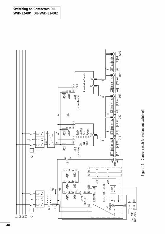
Measures for higher safety categories
In many applications controllers of safety category 3 or 4 in accordance with EN 954-1 are required. Controllers of category 3 can be set up by means of an additional group contactor which is connected in series upstream of the motor junctions. In an emergency the control voltage for the motor contactors and for the group contactor are switched off via the safety relay. This redundant switching-off makes category 3 controllers possible.
47
Switching on Contactors DIL-SWD-32-001, DIL-SWD-32-002
48
Figu
re 1
7:Co
ntro
l circ
uit f
or re
dund
ant s
witc
h-of
f
L1 L2 L3 PE
II
I
-Q1
-K02
-K01
-T01
-K01
-F01
K1
-S02-Q
15
-Q16
-Q16
II
I
-Q1
400
0
e e
e e
e-F
02
24 V
0 V
24 V
0 V
240
-K03
-F03
13 14
13 1421 2221 22
A1A2
S34
S35
13 14
CH1
CH2
K1
23 24
33 34
2~H
-K01
24 V
0 V
-F04
23 24
33 34
8 -Q11
A1X0
X1X2
A2
A1 A2X3
X4-Q
12
A1X0
X1X2
A2X3
X4-Q
13
A1X0
X1X2
A2X3
X4-Q
14
A1X0
X1X2
A2X3
X4-Q
15
A1X0
X1X2
A2X3
X4
88
88
8
-Q14
-Q13
22 2122 21-Q
11
-Q12
21 2221 22
++
+–
–
-S01
1.21
1.13
1.22
1.14
RESE
T
RESE
T
POW
ER
CON
TRO
L-LO
GIC
SWD
In NET
Gat
eway
Pow
er-F
eede
r
Smar
tWire
-Dar
win
Out
Out
Out
In
Conf
igBu
sPo
wer
Aux
NOT
AUS

Engineering
Figu
re 1
8:M
ains
circ
uit f
or re
dund
ant s
witc
h of
f.
PEL1 L2 PEL3
-M1
3~M
UV
WPE
UV
WPE
-Q1
13
5
I>I>
I>2
46
-M1
-Q11
13
5
24
6
-M1
3~M
UV
WPE
UV
WPE
-Q2
13
5
I>I>
I>2
46
-M2
-Q12
13
5
24
6
-M1
3~M
UV
WPE
UV
WPE
-Q3
13
5
I>I>
I>2
46
-M3
-Q13
13
5
24
6
-M1
3~M
UV
WPE
UV
WPE
-Q4
13
5
I>I>
I>2
46
-M4
-Q14
13
5
24
6
-M1
3~M
UV
WPE
UV
WPE
-Q5
13
5
I>I>
I>2
46
-M5
-Q15
13
5
24
6-Q
16
-F1
13
5
24
6
49

Switching on Contactors DIL-SWD-32-001, DIL-SWD-32-002
50
Application for EN ISO13849-1 and EN 62061
The SmartWire-Darwin system is allowed for applications in accordance with EN ISO 13849-1 and EN 62061.
As long as the requirements of the overall system are fulfilled the SmartWire-Darwin system can be used in applications with up to one PL d in accordance with EN ISO 13849-1 and SIL CL 2 in compliance with EN 62061.
Applications in North America
For applications for the North American market special care must be taken with the approval of the individual components of the system SmartWire-Darwin.
Current carrying capacity of the SmartWire-Darwin connecting cable in accordance with NFPA 79If the SmartWire-Darwin connection system is used for applications in North America, the maximum current carrying capacity of the SmartWire-Darwin connecting cable is reduced from 3 A to 2 A.
If, due to the application, the maximum current carrying capacity of the SmartWire-Darwin connecting cable exceeds the value 2 A, this can be compensated by means of additional SmartWire Darwin power feeder modules (a chapter "Power Module EU5C-SWD-PF1-1, EU5C-SWD-PF2-1").
j Danger! The total assembly of the safety relevant controls must correspond to the required safety category.

Engineering
DOL StartersWith the use of DOL starters in the North American market various special features must be observed that are based on market practices and the associated Standards.
Reversing startersBesides the special features described in the aforegoing subsection “Direct starters”, it must be taken into account that reversing starters in the North American market must be equipped in addition with a mechanical and electrical locking device. The electrical locking is realized via the connection auxiliary contact enable h.
h A comprehensive overview of the special North American features is provided by the Moeller publication “Special Conditions for the Use of Protective Motor Switches and Motor Starters in North America”, VER1210+1280-928. You can find this in the form of a PDF document at the following Internet address:
www.moeller.net/binary/ver_techpapers/ver928de.pdf.
51

Switching on Contactors DIL-SWD-32-001, DIL-SWD-32-002
52
Installation The SmartWire-Darwin modules DIL-SWD-32-001 and DIL-SWD-32-002 for DILM must be adapted to the corresponding contactor size prior to installation. The adjustment required for this is performed by means of the adjusting slide of the SmartWire-Darwin module for DILM.
X Set the setting slider on the SmartWire-Darwin module for the corresponding contactor.
• Bottom position: DILA, DILM7, DILM9, DILM12, DILM15• Top position: DILM17, DILM25, DILM32, DILM38
Figure 19: Adjustment of the adjusting slide onDIL-SWD-32-001 or DIL-SWD-32-002
X Place the SmartWire-Darwin module for DILM on the allocated contactor.
h Caution!The SmartWire-Darwin module for DILM may be installed and detached only after the control voltage and supply cable have been switched off.
Position bottom Position top

Installation
Figure 20: Placement of the DIL-SWD-32-001 or DIL-SWD-32-002 onto the contactor
X Lock the SmartWire-Darwin module for DILM
Figure 21: Locking of the DIL-SWD-32-001 or DIL-SWD-32-002
X Connect the SmartWire-Darwin external device plug with the adapted SmartWire-Darwin connecting cable.
DILA, DILM7, DILM9, DILM12, DILM15 DILM17, DILM25, DILM32, DILM38
DILA, DILM7, DILM9, DILM12, DILM15 DILM17, DILM25, DILM32, DILM38
53

Switching on Contactors DIL-SWD-32-001, DIL-SWD-32-002
54
Figure 22: Connection of SmartWire-Darwin external device plug
Commissioning The automatic addressing of all slaves in the SmartWire-Darwin network is performed via the gateway (actuation of the configuration pushbutton on the gateway) during initial operation. During the addressing process the SmartWire-Darwin diagnostics LED flashes. Once the addressing process is completed, the LED indicates a green continuous light.
1
2
SWD4-8SF2-5
+ 15V
SWD4-8SF2-5
+ 15V
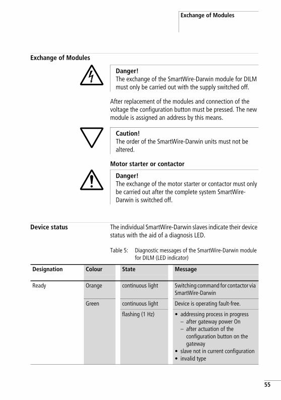
Exchange of Modules
Exchange of Modules
After replacement of the modules and connection of the voltage the configuration button must be pressed. The new module is assigned an address by this means.
Motor starter or contactor
Device status The individual SmartWire-Darwin slaves indicate their device status with the aid of a diagnosis LED.
Table 5: Diagnostic messages of the SmartWire-Darwin module for DILM (LED indicator)
j Danger!The exchange of the SmartWire-Darwin module for DILM must only be carried out with the supply switched off.
h Caution!The order of the SmartWire-Darwin units must not be altered.
i Danger!The exchange of the motor starter or contactor must only be carried out after the complete system SmartWire-Darwin is switched off.
Designation Colour State Message
Ready Orange continuous light Switching command for contactor via SmartWire-Darwin
Green continuous light Device is operating fault-free.
flashing (1 Hz) • addressing process in progress– after gateway power On– after actuation of the
configuration button on the gateway
• slave not in current configuration• invalid type
55

Switching on Contactors DIL-SWD-32-001, DIL-SWD-32-002
56
Programming DIL-SWD-32-001
The function element has one input byte and one output byte at its disposal.
InputsByte 0:
7 6 5 4 3 2 1 0
- P - F - I1 (X1-X0)
I0 (X1-X2)
C
Bit Designation Meaning
0 C = Contactor 0: contactor not tripped1: contactor tripped
1 I0 (X1-X2) 0: Auxiliary contact for X1-X2 opened1: Auxiliary contact for X1-X2 closedThe meaning depends on the auxiliary switch used.
2 I1 (X1-X0) 0: Auxiliary contact for X1-X0 opened1: Auxiliary contact for X1-X0 closedThe meaning depends on the auxiliary switch used.
3 not used -
4 F = Failure 0: No diagnostic alarm
5 not used -
6 P = Module present 0: Module not available1: Module available
7 not used -

Programming
OutputsByte 0:
DiagnosticsThe module does not report a diagnosis.
7 6 5 4 3 2 1 0
- - - - - - - Q0
Bit Designation Meaning
0 Q0 Contactor actuation
1 not used -
2 not used -
3 not used -
4 not used -
5 not used -
6 not used -
7 not used -
57

Switching on Contactors DIL-SWD-32-001, DIL-SWD-32-002
58
DIL-SWD-32-002
The function element has one input byte and one output byte at its disposal.
InputsByte 0:
7 6 5 4 3 2 1 0
- P - F M I1 (X1-X0)
I0 (X1-X2)
C
Bit Designation Meaning
0 C = Contactor 0: contactor not tripped1: contactor tripped
1 I0 (X1-X2) 0: Auxiliary contact for X1-X2 opened1: Auxiliary contact for X1-X2 closedThe meaning depends on the auxiliary switch used.
2 I1 (X1-X0) 0: Auxiliary contact for X1-X0 opened1: Auxiliary contact for X1-X0 closedThe meaning depends on the auxiliary switch used.
3 M = Manual 0: Automatic1: Manual mode
4 F = Failure 0: No diagnostic alarm
5 not used -
6 P = Module present 0: Module not available1: Module available
7 not used -

Programming
OutputsByte 0:
DiagnosticsThe module does not report a diagnosis.
7 6 5 4 3 2 1 0
- - - - - - - Q0
Bit Designation Meaning
0 Q0 Contactor actuation
1 not used -
2 not used -
3 not used -
4 not used -
5 not used -
6 not used -
7 not used -
59

60

02/09 AWB2723-1613en
4 Control Circuit DevicesM22-SWD…
Introduction The function elements M22-SWD... are combined together with front elements of the RMQ Titan system to form control circuit devices that are capable of communication. The switch position indications of the control elements and activation of the indicator lights takes place via the SmartWire-Darwin communication system. The following function elements are available.
These function elements are each available in two versions for front or base fixing.
Function element Description
M22-SWD-K(C)11 a function element with a changeover contact
M22-SWD-K(C)22 a function element with two changeover contacts
M22-SWD-LED… an LED function element in white (W), red (R), green (G) or blue (B)
M22-SWD-K11LED… a function element with a changeover contact and an LED in white (W), red (R), green (G) or blue (B)
M22-SWD-K22LED… a function element with two changeover contacts and an LED in white (W), red (R), green (G) or blue (B)
61

Control Circuit Devices M22-SWD…
62
02/09 AWB2723-1613en
M22-SWD front fixing M22-SWD front function elements are used in connection with the M22-A adapter and M22 front elements for installation in consoles or control box doors.
Layout
Figure 23: Layout M22-SWD front fixing
M22-SWD-K…M22-SWD-LED…
SWD-8SF2-5
M22…
SWD4-…LF…

Engineering02/09 AWB2723-1613en
Engineering The SmartWire-Darwin front function elements are used instead of the previous M22-K10-/K01 contact elements and the corresponding M22 LED....indicator elements. The previous elements for the control circuit function are used on the front.
One SmartWire function element is used per M22-A adapter. Mounting is always performed in the middle position. Correspondingly more efficient function elements are used for the combined functions of a luminous command device or for the realization of a multi-step switch. An illuminated pushbutton, which previously had to be realized as a combination of several elements, can now be realized simply by means of one combination element (LED indicator + contact element = M22-SWD-K11LED).
M22-SWD-K11This function element replaces the previous contact elements M22-K10/K01. It provides a changeover contact by means of which both a breaker and maker function can be realized. The previously possible “piggy-back” combination consisting of an M22-K01 and -K10 element can also be replaced by a single M22-SWD-K11 element. The function element is used in combination with M22 (pushbutton) actuators.
M22-SWD-K22This function element replaces multiple combinations of the previous contact elements M22-K10/K01. It provides two changeover contacts, by means of which control switches can be operator controlled with up to three-position indication.
h Further M22-K10-/01 contact elements can be installed here in the free location of the M22-A adapter.
A possible application is, for example, conventional switching via an M22-K... contact element and the reporting of this process to the PLC via the M22-SWD-K11 function element.
63

Control Circuit Devices M22-SWD…
64
02/09 AWB2723-1613en
M22-SWD-LED…This function element is used in combination with the indicator lights M22-L.... White, blue, green and red are available as colours.
M22-SWD-K11LED…This function element contains a changeover contact and an LED in the colours white, blue, green and red.
The function element replaces previous combinations of a contact element M22-K01 or -K10 and an M22 LED element. It is used in combination with luminous pushbuttons or selector buttons.
M22-SWD-K22LED…This function element contains two changeover contacts and an LED in the colours white, blue, green and red.
The function element replaces previous combinations consisting of several contact elements M22-K01 or -K10 and an M22 LED element. It is used in combination with luminous 3-position selector switches.
All possibilities of combining M22 front elements with SmartWire-Darwin function elements for front fixing are listed in the following table.
Figure 24: SWD function elements
h The adapter M22-SWD-A4, which can then accommodate two M22-SWD-K22 function elements, is used for 4-position contact polling (e.g. joystick M22S-WJ4) instead of the adapter M22-A4.

Engineering02/09 AWB2723-1613en
Table 6: Possibilities of combining the M22 front element with SWD function elements
The SmartWire-Darwin function element always occupies the middle slot of the M22 adapter. If required, standard M22-K10/K01 contact elements can also be plugged into the free slots. The M22-SWD-A4 adapter is fitted with two M22-SWD-K22 function elements.
The following table shows what possibilities there are for this.
Front element Adapters SmartWire-Darwin function element (front fixing)
M22(S)-PV(T) M22-A M22-SWD-K11
M22(S)-PVL(T) M22-A M22-SWD-K11LED
M22(S)-DDL M22-A M22-SWD-K22LED
M22(S)-D(R)(H) M22-A M22-SWD-K11
M22(S)-D(R)P M22-A M22-SWD-K11
M22(S)-W(R)K M22-A M22-SWD-K11
M22(S)-WKV M22-A M22-SWD-K11
M22(S)-W(R)K3 M22-A M22-SWD-K22
M22(S)-W(R)S-(SA) M22-A M22-SWD-K11
M22(S)-W(R)S3-(SA) M22-A M22-SWD-K22
M22(S)-L(H) M22-A M22-SWD-LED
M22(S)-D(R)L(H) M22-A M22-SWD-K11LED
M22(S)-W(R)LK M22-A M22-SWD-K11LED
M22(S)-W(R)LK-3 M22-A M22-SWD-K22LED
M22(S)-WLKV-3 M22-A M22-SWD-K22LED
M22(S)-W…4… M22-SWD-A4 2 x M22-SWD-K22
M22(S)-D…4… M22-SWD-A4 2 x M22-SWD-K22
M22-WJ2… M22-SWD-A4 2 x M22-SWD-K22
65

Control Circuit Devices M22-SWD…
66
02/09 AWB2723-1613en
Table 7: Configurations of the M22-A adapter
Function element Configuration of the M22-A adapter (front fixing) (viewed from the rear while equipping the adapter)
Marking on adapter 1/4 3/6 2/5
M22-SWD-K11 O X1) O2)
M22-SWD-LED O X O
M22-SWD-K11LED O X O
M22-SWD-K22 O X X
M22-SWD-K22LED O X X
1) X = occupied by SWD element2) O = optional for an additional M22-K10/K01 element
h The function elements obtain the energy for communication electronics and driving the LED from the SmartWire-Darwin network supply.
Please take into consideration the total current consumption of your SmartWire network and, if necessary, plan for an additional feeder module EU5C-SWD-PF2-1. You will find information on the current consumption in the appendix on page 103.
The software programme SWD-Assist also supports you in doing this by automatically performing these calculations.
Installation02/09 AWB2723-1613en
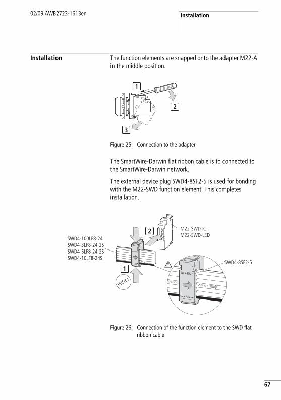
Installation The function elements are snapped onto the adapter M22-A in the middle position.
Figure 25: Connection to the adapter
The SmartWire-Darwin flat ribbon cable is to connected to the SmartWire-Darwin network.
The external device plug SWD4-8SF2-5 is used for bonding with the M22-SWD function element. This completes installation.
Figure 26: Connection of the function element to the SWD flat ribbon cable
1
3
2
1
2
SWD4-8SF2SWD4-8SF2
SWD4-8SF2-5
+ 15V
SWD4-100LF8-24SWD4-3LF8-24-2SSWD4-5LF8-24-2SSWD4-10LF8-24S
SWD4-8SF2-5
SWD4-8SF2-5
+ 15V
M22-SWD-K...M22-SWD-LED
67

Control Circuit Devices M22-SWD…
68
02/09 AWB2723-1613en
Commissioning The automatic addressing of all slaves in the SmartWire-Darwin network is performed via the gateway (actuation of the configuration pushbutton on the gateway) during initial operation. During the addressing process the SmartWire Darwin diagnosis LED on the rear side of the M22-SWD front function element flashes. Once the addressing process is completed, the LED indicates a green continuous light.
Exchange of Modules
After replacement of the modules and connection of the voltage the configuration button must be pressed. The new module is assigned an address by this means.
h Caution!Replacement of the SmartWire-Darwin function elements is not permitted until the entire SmartWire-Darwin system has been switched off.
h Caution!The sequence of the SmartWire-Darwin slaves must not be altered.

Device status02/09 AWB2723-1613en
Device status The individual SmartWire-Darwin slaves indicate their device status with the aid of the diagnostics LED.
Table 8: Diagnostic messages of the SmartWire-Darwin status LED
Designation Colour State Message
SWD Green continuous light Device is operating fault-free.
Flashing (1 Hz) • addressing process in progress– after gateway power On– after actuation of the
configuration button on the gateway
• slave not in current configuration• invalid type
Flashing (3 Hz) Device reports a diagnostics. (a section "Programming", Subpoint “Diagnostics”.)
69

Control Circuit Devices M22-SWD…
70
02/09 AWB2723-1613en
Programming The various function elements have specific input/output information that is processed in the programming system. The meaning and scope are described in the following.
M22-SWD-K11
The function element has one input byte at its disposal.
InputsByte 0:
NO1NC1
7 6 5 4 3 2 1 0
- P - F - - NO1 NC1
Bit Designation Meaning
0 NC1 = Normally Close 0: contact actuated1: contact not actuated
1 NO1 = Normally Open 0: Contact not actuated1: contact actuated
2 not used -
3 not used -
4 F = Failure 0: No diagnostic alarm1: Diagnostics available
5 not used -
6 P = Module present 0: Module not available1: Module available
7 not used -

Programming02/09 AWB2723-1613en
OutputsNone
DiagnosticsIn the event of a diagnosis the module reports the following error causes (0 is set for bit 4 in the input byte):
Value Meaning
0x10 The contact is in the middle position for longer than four seconds.
0x11 Contact short-circuit
71

Control Circuit Devices M22-SWD…
72
02/09 AWB2723-1613en
M22-SWD-K22
The function element has one input byte at its disposal.
InputsByte 0:
NO1NC1
NO2NC2
7 6 5 4 3 2 1 0
- P - F NO2 NC2 NO1 NC1
Bit Designation Meaning
0 NC1 = Normally Close 0: contact 1 actuated1: contact 1 not actuated
1 NO1 = Normally Open 0: Contact 1 not actuated1: contact 1 actuated
2 NC2 = Normally Close 0: contact 2 actuated1: contact 2 not actuated
3 NO2 = Normally Open 0: contact 2 not actuated1: contact 2 actuated
4 F = Failure 0: No diagnostic alarm1: Diagnostics available
5 not used -
6 P = Module present 0: Module not available1: Module available
7 not used -

Programming02/09 AWB2723-1613en
OutputsNone
DiagnosticsIn the event of a diagnosis the module reports the following error causes (0 is set for bit 4 in the input byte):
Value Meaning
0x10 The contact is in the middle position for longer than four seconds.
0x11 Contact short-circuit
73

Control Circuit Devices M22-SWD…
74
02/09 AWB2723-1613en
M22-SWD-LED-(W/B/G/R)
The function element has one input byte and one output byte at its disposal.
InputsByte 0:
7 6 5 4 3 2 1 0
- P - F - - - -
Bit Designation Meaning
0 not used -
1 not used -
2 not used -
3 not used -
4 F = Failure 0: No diagnostic alarm
5 not used -
6 P = Module present 0: Module not available1: Module available
7 not used -

Programming02/09 AWB2723-1613en
OutputsByte 0:
DiagnosticsThe module does not report a diagnosis.
7 6 5 4 3 2 1 0
- - - - - - - Q0
Bit Designation Meaning
0 Q0 Activation of the LED
1 not used -
2 not used -
3 not used -
4 not used -
5 not used -
6 not used -
7 not used -
75

Control Circuit Devices M22-SWD…
76
02/09 AWB2723-1613en
M22-SWD-K11LED-(W/B/G/R)
The function element has one input byte and one output byte at its disposal.
InputsByte 0:
NO1NC1
7 6 5 4 3 2 1 0
- P - F - - NC1 NC1
Bit Designation Meaning
0 NC1 = Normally Close 0: contact actuated1: contact not actuated
1 NO = Normally Open 0: Contact not actuated1: contact actuated
2 not used -
3 not used -
4 F = Failure 0: No diagnostic alarm1: Diagnostics available
5 not used -
6 P = Module present 0: Module not available1: Module available
7 not used -

Programming02/09 AWB2723-1613en
OutputsByte 0:
OutputsNone
DiagnosticsIn the event of a diagnosis the module reports the following error causes (0 is set for bit 4 in the input byte):
7 6 5 4 3 2 1 0
- - - - - - - Q0
Bit Designation Meaning
0 Q0 Activation of the LED
1 not used -
2 not used -
3 not used -
4 not used -
5 not used -
6 not used -
7 not used -
Value Meaning
0x10 The contact is in the middle position for longer than four seconds.
0x11 Contact short-circuit
77

Control Circuit Devices M22-SWD…
78
02/09 AWB2723-1613en
M22-SWD-K22LED-(W/B/G/R)
The function element has one input byte and one output byte at its disposal.
InputsByte 0:
NO2NC2
NO1NC1
7 6 5 4 3 2 1 0
- P - F NO2 NC2 NO1 NC1
Bit Designation Meaning
0 NC1 = Normally Close 0: contact 1 actuated1: contact 1 not actuated
1 NO1 = Normally Open 0: Contact 1 not actuated1: contact 1 actuated
2 NC2 = Normally Close 0: contact 2 actuated1: contact 2 not actuated
3 NO2 = Normally Open 0: contact 2 not actuated1: contact 2 actuated
4 F = Failure 0: No diagnostic alarm1: Diagnostics available
5 not used -
6 P = Module present 0: Module not available1: Module available
7 not used -

Programming02/09 AWB2723-1613en
OutputsByte 0:
OutputsNone
DiagnosticsIn the event of a diagnosis the module reports the following error causes (0 is set for bit 4 in the input byte):
7 6 5 4 3 2 1 0
- - - - - - - Q0
Bit Designation Meaning
0 Q0 Activation of the LED
1 not used -
2 not used -
3 not used -
4 not used -
5 not used -
6 not used -
7 not used -
Value Meaning
0x10 The contact is in the middle position for longer than four seconds.
0x11 Contact short-circuit
79

Control Circuit Devices M22-SWD…
80
02/09 AWB2723-1613en
M22-SWD base fixing
M22-SWD base function elements are used in connection with M22-I... surface mounting enclosures and M22 front elements.
Layout
Figure 27: Base elements with enclosure
132
132
132
IN
OUT
OFF
ON

Engineering02/09 AWB2723-1613en
Engineering The SmartWire-Darwin base function elements replace the previous M22-KC10 / KC01 contact elements and the corresponding M22 LEDC... elements. They are used in the surface mounting enclosures M22-I1 to M22-I6 in connection with the corresponding M22-SWD-ILP1-6 PCBs. Up to six operator control and indicator light functions can be realized with them. The printed circuit boards create the connection with the SmartWire-Darwin network. The known M22 front elements for the control circuit function are used on the front.
The surface mounting enclosures are connected to the SmartWire-Darwin network via the SmartWire-Darwin round cable SWD4-50LR8-24.
The round cable can be connected directly by means of VM20 (metric cable gland) or plugged in. 8-pole enclosure bushings as plug/socket versions are used for the plug-in version.
Connection of the round cable to the cable gland
Figure 28: Connection with a cable gland
1322
IN
V-M20
81

Control Circuit Devices M22-SWD…
82
02/09 AWB2723-1613en
Connection of the round cable via a plug connection
The SmartWire-Darwin PCB is connected via 8-pole enclosure bushings executed as sockets or plugs.
Figure 29: Plug connection
Connection to the round cable in this case is via 8-pole plugs/sockets.
Housing bushing socket SWD Element
Housing bushing socket for M22 SWD4-SF8-20
Housing bushing plug for M22 SWD4-SM8-20
132132
132
IN
OUT
OFFO
N
SWD4-SF8-20
SWD4-SM8-20
IN
OUT
Housing bushing socket SWD Element
Socket, straight, 8-pole SWD4-SF8-67
Plug, straight, 8-pole SWD4-SM8-67
Socket, angled at 90°, 8-pole SWD4-SF8-67W
Plug, angled at 90°, 8-pole SWD4-SM8-67W

Engineering02/09 AWB2723-1613en
One SmartWire-Darwin function element is used per slot. Correspondingly more efficient function elements are used for the combined function of a luminous command device or for the realization of a multi-step switch.
A luminous pushbutton, which previously had to be realized as a combination of several elements, can now be realized simply by means of one combination element (LED indicator + contact element = M22-SWD-K11LEDC).
M22-SWD-KC11This function element replaces the previous contact elements M22-KC10/KC01. It provides a changeover contact by means of which both a breaker and maker function can be realized. The function element is used in combination with M22 (pushbutton) actuators.
h Non-used slots have to be equipped with the SmartWire-Darwin bridge M22-SWD-SEL8-10, otherwise the SmartWire-Darwin network will be interrupted.
h The PCBs contain a switchable terminating resistor for the SmartWire-Darwin network. If the surface mounting enclosure is the last slave in the network, the terminating resistor must be switched on.
h You can also obtain information about terminating resistors and on the use of the SWD bridge via the software program SWD-Assist.
http://downloadcenter.moeller.net
83

Control Circuit Devices M22-SWD…
84
02/09 AWB2723-1613en
M22-SWD-KC22This function element replaces multiple combinations of the previous contact elements M22-KC10/KC01. It provides two changeover contacts, by means of which control switches can be operated with up to three-position indication.
M22-SWD-LEDC…This function element is used in combination with the indicator lights M22-L.... White, blue, green or red are available as colours.
M22-SWD-K11LEDC… (Multiple Function Elements)These functional elements contain a changeover contact and an LED element in the colours white, blue, green and red. They replace previous combinations consisting of a contact element M22-KC01 or -KC10 and an M22 LEDC... element. They are used in combination with illuminated pushbuttons or selector switch buttons.
M22-SWD-K22LEDC… (multiple function elements)These functional elements contain two changeover contacts and an LED element in the colours white, blue, green and red. They replace previous combinations consisting of several contact elements M22-KC01 or -KC10 and an M22-LEDC... element. They are used in combination with luminous 3-position selector switches.
h Further M22-KC10-/KC01 contact elements can be installed here in the free locations in the surface mounting enclosure.
A possible application is, for example, conventional switching via an M22-K... contact element and the reporting of this process to the PLC via the M22-SWD-K11 function element.
h Further M22-KC... contact elements can be installed here in the free locations in the surface mounting enclosure.
h There is no possibility of connecting an M22S-WJ4 joystick element.
Engineering02/09 AWB2723-1613en
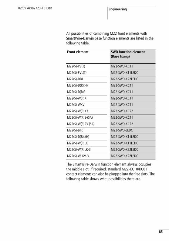
All possibilities of combining M22 front elements with SmartWire-Darwin base function elements are listed in the following table.
The SmartWire-Darwin function element always occupies the middle slot. If required, standard M22-KC10/KC01 contact elements can also be plugged into the free slots. The following table shows what possibilities there are.
Front element SWD function element(Base fixing)
M22(S)-PV(T) M22-SWD-KC11
M22(S)-PVL(T) M22-SWD-K11LEDC
M22(S)-DDL M22-SWD-K22LEDC
M22(S)-D(R)(H) M22-SWD-KC11
M22(S)-D(R)P M22-SWD-KC11
M22(S)-W(R)K M22-SWD-KC11
M22(S)-WKV M22-SWD-KC11
M22(S)-W(R)K3 M22-SWD-KC22
M22(S)-W(R)S-(SA) M22-SWD-KC11
M22(S)-W(R)S3-(SA) M22-SWD-KC22
M22(S)-L(H) M22-SWD-LEDC
M22(S)-D(R)L(H) M22-SWD-K11LEDC
M22(S)-W(R)LK M22-SWD-K11LEDC
M22(S)-W(R)LK-3 M22-SWD-K22LEDC
M22(S)-WLKV-3 M22-SWD-K22LEDC
85

Control Circuit Devices M22-SWD…
86
02/09 AWB2723-1613en
Table 9: Configuration in the M22-I… enclosure
Function element M22-I… enclosure configuration (base fixing)(viewed from the front while equipping the enclosure)
Location on the PCB(marking on the enclosure base)
2 3 1
M22-SWD-KC11 O X1) O2)
M22-SWD-LEDC O X O
M22-SWD-K11LEDC O X O
M22-SWD-KC22 X X O
M22-SWD-K22LEDC X X O
M22-SWD-SEL-8-10 O X O
1) X = occupied by SWD element2) O = optional for an additional M22-KC10/ KC01 element
h The function elements obtain the energy for communication electronics and driving the LEDs from the SmartWire-Darwin network supply. So please take into consideration the total current consumption of your SmartWire-Darwin network and, if necessary, plan for an additional feeder module EU5E-SWD-PF2-1.
You can find information on the current consumption in the appendix on page 103.
The software programme SWD-Assist also supports you in doing this by automatically performing these calculations.
http://downloadcenter.moeller.net

Installation02/09 AWB2723-1613en
Installation The functional elements are mounted on the PCB M22-SWD-ILP… in the surface mounting enclosure M22-I….
To do so, proceed as follows:
X Insert the printed circuit board into the surface mounting enclosure. Ensure that the PCB is pointing in the correct direction. The direction of the arrow defines the arrangement of the slaves (the gateway is to the left of the IN code).
Figure 30: Surface-mounting enclosure with PCB M22-SWD-ILP…
132132
132
IN
OU
TOF
FON
ON OFF
M22-SWD4-SF8-20
M22-SWD4-SM8-20
M22-I…
87

Control Circuit Devices M22-SWD…
88
02/09 AWB2723-1613en
X Fix the SWD cables to the PCB terminals. Ensure that the colour assignment is correct.
X If this is the last SWD slave, please switch on the terminating resistor.
Figure 31: Terminating resistor
X Equip the slots with the M22-SWD…C… function elements. Ensure that the installation position is correct (status LED at the top). Unused slots must be equipped with the bridge M22-SWD-SEL8 10.
OU
T
OFF
ON
ONOFF
abcdefgh

Installation02/09 AWB2723-1613en
Figure 32: Equipping the enclosure slots
132
132
132
IN
OUT
OFF
ON
CLICK!
IN OUT
89

Control Circuit Devices M22-SWD…
90
02/09 AWB2723-1613en
Commissioning The automatic addressing of all slaves in the SmartWire-Darwin network is performed via the gateway (actuation of the configuration pushbutton on the gateway) during initial operation. During the addressing process the SmartWire-Darwin diagnostics LED on the top side of the M22 SmartWire-Darwin base function element flashes. Once the addressing process is completed, the LED indicates a green continuous light.
Exchange of Modules
After replacement of the modules and connection of the voltage the configuration button must be pressed. The new module is assigned an address by this means.
h Caution!Replacement of the SmartWire-Darwin function elements is not permitted until the entire SmartWire-Darwin system has been switched off.
h Caution!The sequence of the SmartWire-Darwin slaves must not be altered.

Device status02/09 AWB2723-1613en
Device status The individual SmartWire-Darwin slaves indicate their device status with the aid of the diagnostics LED.
Table 10: Diagnostic messages of the SmartWire-Darwin status LED
Designation Colour State Message
SWD Green continuous light Device is operating fault-free.
flashing (1 Hz) • addressing process in progress– after gateway power On– after actuation of the
configuration button on the gateway
• slave not in current configuration• invalid type
Flashing (3 Hz) Device reports a diagnostics. (a section "Programming", Subpoint “Diagnostics”.)
Designation Colour State Message
SWD Green continuous light Device is operating fault-free.
Flashing Device is not in the configuration, first faulty device in the series – no communication
pulsating flash The SmartWire-Darwin module is carrying a voltage, the previous device has caused an error – no communication pending
91

Control Circuit Devices M22-SWD…
92
02/09 AWB2723-1613en
Programming The various function elements have specific input/output information that is processed in the programming system. The meaning and scope are described in the following.
M22-SWD-KC11
The function element has one input byte at its disposal.
Inputs
Byte 0:
NO1NC1
7 6 5 4 3 2 1 0
- P - F - - NC1 NC1
Bit Designation Meaning
0 NC1 = Normally Close 0: contact actuated1: contact not actuated
1 NO1 = Normally Open 0: Contact not actuated1: contact actuated
2 not used -
3 not used -
4 F = Failure 0: No diagnostic alarm1: Diagnostics available
5 not used -
6 P = Module present 0: Module not available1: Module available
7 not used -

Programming02/09 AWB2723-1613en
OutputsNone
DiagnosticsIn the event of a diagnosis the module reports the following error causes (0 is set for bit 4 in the input byte):
Value Meaning
0x10 The contact is in the middle position for longer than four seconds.
0x11 Contact short-circuit
93

Control Circuit Devices M22-SWD…
94
02/09 AWB2723-1613en
M22-SWD-KC22
The function element has one input byte at its disposal.
InputsByte 0:
NO2NC2
NO1NC1
7 6 5 4 3 2 1 0
- P - F NO2 NC2 NO1 NC1
Bit Designation Meaning
0 NC1 = Normally Close 0: contact 1 actuated1: contact 1 not actuated
1 NO1 = Normally Open 0: Contact 1 not actuated1: contact 1 actuated
2 NC2 = Normally Close 0: contact 2 actuated1: contact 2 not actuated
3 NO2 = Normally Open 0: contact 2 not actuated1: contact 2 actuated
4 F = Failure 0: No diagnostic alarm1: Diagnostics available
5 not used -
6 P = Modules present 0: Module not available1: Module available
7 not used -

Programming02/09 AWB2723-1613en
OutputsNone
DiagnosticsIn the event of a diagnosis the module reports the following error causes (0 is set for bit 4 in the input byte):
Value Meaning
0x10 The contact is in the middle position for longer than four seconds.
0x11 Contact short-circuit
95

Control Circuit Devices M22-SWD…
96
02/09 AWB2723-1613en
M22-SWD-LEDC-(W/B/G/R)
The function element has one input byte and one output byte at its disposal.
InputsByte 0:
7 6 5 4 3 2 1 0
- P - F - - - -
Bit Designation Meaning
0 not used -
1 not used -
2 not used -
3 not used -
4 F = Failure 0: No diagnostic alarm
5 not used -
6 P = Modules present 0: Module not available1: Module available
7 not used -

Programming02/09 AWB2723-1613en
OutputsByte 0:
DiagnosticsThe module does not report a diagnosis.
7 6 5 4 3 2 1 0
- - - - - - - Q0
Bit Designation Meaning
0 Q0 Activation of the LED
1 not used -
2 not used -
3 not used -
4 not used -
5 not used -
6 not used -
7 not used -
97

Control Circuit Devices M22-SWD…
98
02/09 AWB2723-1613en
M22-SWD-K11LEDC-(W/B/G/R)
The function element has one input byte and one output byte at its disposal.
InputsByte 0:
NO1NC1
7 6 5 4 3 2 1 0
- P - F - - NC1 NC1
Bit Designation Meaning
0 NC1 = Normally Close 0: contact actuated1: contact not actuated
1 NO = Normally Open 0: Contact not actuated1: contact actuated
2 not used -
3 not used -
4 F = Failure 0: No diagnostic alarm1: Diagnostics available
5 not used -
6 P = Module present 0: Module not available1: Module available
7 not used -

Programming02/09 AWB2723-1613en
OutputsByte 0:
OutputsNone
DiagnosticsIn the event of a diagnosis the module reports the following error causes (0 is set for bit 4 in the input byte):
7 6 5 4 3 2 1 0
- - - - - - - Q0
Bit Designation Meaning
0 Q0 Activation of the LED
1 not used -
2 not used -
3 not used -
4 not used -
5 not used -
6 not used -
7 not used -
Value Meaning
0x10 The contact is in the middle position for longer than four seconds.
0x11 Contact short-circuit
99
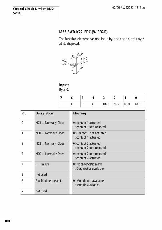
Control Circuit Devices M22-SWD…
100
02/09 AWB2723-1613en
M22-SWD-K22LEDC-(W/B/G/R)
The function element has one input byte and one output byte at its disposal.
InputsByte 0:
NO1NC1NO2
NC2
7 6 5 4 3 2 1 0
- P - F NO2 NC2 NO1 NC1
Bit Designation Meaning
0 NC1 = Normally Close 0: contact 1 actuated1: contact 1 not actuated
1 NO1 = Normally Open 0: Contact 1 not actuated1: contact 1 actuated
2 NC2 = Normally Close 0: contact 2 actuated1: contact 2 not actuated
3 NO2 = Normally Open 0: contact 2 not actuated1: contact 2 actuated
4 F = Failure 0: No diagnostic alarm1: Diagnostics available
5 not used -
6 P = Module present 0: Module not available1: Module available
7 not used -
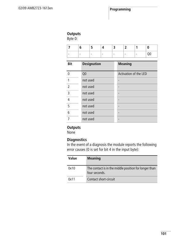
Programming02/09 AWB2723-1613en
OutputsByte 0:
OutputsNone
DiagnosticsIn the event of a diagnosis the module reports the following error causes (0 is set for bit 4 in the input byte):
7 6 5 4 3 2 1 0
- - - - - - - Q0
Bit Designation Meaning
0 Q0 Activation of the LED
1 not used -
2 not used -
3 not used -
4 not used -
5 not used -
6 not used -
7 not used -
Value Meaning
0x10 The contact is in the middle position for longer than four seconds.
0x11 Contact short-circuit
101

102
02/09 AWB2723-1613en

02/09 AWB2723-1613en
Appendix
Maximum current consumption
The following table shows the maximum current consumption of the individual function elements.
Current consumption 15-V-SWD supply voltage
Type Article no. Current consumption Notesm A
M22-SWD-K11 115964 7 –M22-SWD-K22 115965 7 –M22-SWD-LED-W 115966 19 –M22-SWD-LED-B 115967 19 –M22-SWD-LED-G 115968 19 –M22-SWD-LED-R 115969 19 –M22-SWD-K11LED-W 115972 19 –M22-SWD-K11LED-B 115973 19 –M22-SWD-K11LED-G 115974 19 –M22-SWD-K11LED-R 115975 19 –M22-SWD-K22LED-W 115978 19 –M22-SWD-K22LED-B 115979 19 –M22-SWD-K22LED-G 115980 19 –M22-SWD-K22LED-R 115981 19 –M22-SWD-KC11 115995 7 –M22-SWD-KC22 115996 7 –M22-SWD-LEDC-W 115997 19 –M22-SWD-LEDC-B 115998 19 –M22-SWD-LEDC-G 115999 19 –M22-SWD-LEDC-R 116000 19 –M22-SWD-K11LEDC-W 116003 19 –M22-SWD-K11LEDC-B 116004 19 –M22-SWD-K11LEDC-G 116005 19 –M22-SWD-K11LEDC-R 116006 19 –M22-SWD-K22LEDC-W 116009 19 –M22-SWD-K22LEDC-B 116010 19 –M22-SWD-K22LEDC-G 116011 19 –M22-SWD-K22LEDC-R 116012 19 –DIL-SWD-32-001 118560 40 –DIL-SWD-32-002 118561 40 –EU5E-SWD-8DX 116381 12 –
103

Appendix
104
02/09 AWB2723-1613en
Power consumption/current consumption 24-V-SWDcontrol voltage UAUX
EU5E-SWD-4D4D 116382 45 –EU5E-SWD-4D2R 116383 45 –M22-SWD-I1-LP01 115990 17 with terminating
resistor switched onM22-SWD-I2-LP01 115991 17M22-SWD-I3-LP01 115992 17M22-SWD-I4-LP01 115993 17M22-SWD-I6-LP01 115994 17
SWD4-RC8-10 116020 17 –
Type Article no. Current consumption Notesm A
DIL-SWD-32-…
Pick-up powerfor DILM 7-9 W 3for DILM 12-15 W 4.5for DILM 17-38 W 12
Pick-up currentfor DILM 7-9 m A 125for DILM 12-15 m A 188for DILM 17-38 m A 500
Sealing powerfor DILM 7-9 W 3for DILM 12-15 W 4.5for DILM 17-3 W 0.5
Holding currentfor DILM 7-9 m A 125for DILM 12-15 m A 188for DILM 17-38 m A 21

Technical data02/09 AWB2723-1613en
Tech
nica
l dat
aG
atew
ays,
Pow
er F
eede
r M
odul
es
EU5C
-SW
D-D
PEU
5C-S
WD
-CA
NEU
5C-S
WD
-PF1
-1EU
5C-S
WD
-PF2
-1
Gen
eral
Stan
dard
sIE
C/EN
611
31-2
, EN
501
78IE
C/EN
611
31-2
, EN
501
78Di
men
sions
(W x
H x
D)
mm
35 X
90 X
127
35 X
90 X
124
Wei
ght
kg0.
160.
160.
110.
17M
ount
ing
Top-
hat r
ail I
EC/E
N 6
0715
, 35
mm
To
p-ha
t rai
l IEC
/EN
607
15, 3
5 m
m
Mou
ntin
g po
sitio
nve
rtica
lve
rtica
l
Am
bien
t m
echa
nica
l con
diti
ons
Prot
ectio
n ty
pe (I
EC/E
N 6
0529
)IP
20IP
20IP
20IP
20Vi
brat
ions
(IEC
/EN
611
31-2
:200
8)co
nsta
nt a
mpl
itude
3.5
mm
Hz5
… 8
.45
… 8
.45
… 8
.45
… 8
.4co
nsta
nt a
ccel
erat
ion
1 g
Hz8.
4 …
150
8.4
… 1
508.
4 …
150
8.4
… 1
50M
echa
nica
l sho
ck re
sista
nce
(IEC/
EN 6
0068
-2-
27)
sem
i-sin
usoi
dal 1
5 g/
11 m
s
Shoc
ks9
99
9
Drop
to IE
C/EN
600
68-2
-31
Drop
hei
ght
mm
5050
5050
Free
fall,
pac
kage
d (IE
C/EN
600
68-2
-32)
m0.
30.
30.
30.
3
105

Appendix
106
02/09 AWB2723-1613en
Elec
trom
agne
tic
com
pati
bilit
y (E
MC)
Ove
rvol
tage
cat
egor
yII
IIII
IIPo
llutio
n de
gree
22
22
Elec
trost
atic
disc
harg
e (IE
C/EN
611
31-2
:200
8)Ai
r disc
harg
e (L
evel
3)
kV
88
88
Cont
act d
ischa
rge
(Lev
el 2
) k
V4
44
4El
ectro
mag
netic
fiel
ds (I
EC/E
N 6
1131
-2:2
008)
80-1
000
MHz
V/m
1010
1010
1.4
- 2 G
HzV/
m3
33
32
- 2.7
GHz
V/m
11
11
Radi
o in
terfe
renc
e su
ppre
ssio
n (S
mar
tWire
-Dar
win
)EN
550
11 C
lass
AEN
550
11 C
lass
ABu
rst (
IEC/
EN 6
1131
-2:2
008,
Lev
el 3
)Su
pply
cab
les
kV
22
22
CAN
/DP
bus
cabl
e k
V1
1–
–Sm
artW
ire-D
arw
in c
able
s k
V1
11
1Su
rge
(IEC/
EN 6
1131
-2:2
008,
Lev
el 1
)Su
pply
cab
les/
CAN
/DP
bus
cabl
eSu
pply
cab
les
0.5
kV, C
AN/D
P bu
s ca
ble
1 kV
Supp
ly ca
bles
0.5
kV,
CAN
/DP
bus c
able
1
kVRa
diat
ed R
FI (I
EC/E
N 61
131-
2:20
08, L
evel
3)
V10
1010
10
Am
bien
t cl
imat
ic c
ondi
tion
sO
pera
ting
ambi
ent t
empe
ratu
re (I
EC 6
0068
-2)
°C
–25
… +
55–2
5 …
+55
–25
… +
55–2
5 …
+55
Cond
ensa
tion
prev
ent w
ith s
uita
ble
mea
sure
s St
orag
e °
C–4
0…70
–40…
70–4
0…70
–40…
70Re
lativ
e hu
mid
ity, n
on-c
onde
nsin
g (IE
C/EN
60
068-
2-30
)%
5 …
95
5 …
95
5 …
95
5 …
95
EU5C
-SW
D-D
PEU
5C-S
WD
-CA
NEU
5C-S
WD
-PF1
-1EU
5C-S
WD
-PF2
-1

Technical data02/09 AWB2723-1613en
Supp
ly v
olta
ge U
AU
X
Rate
d op
erat
iona
l vol
tage
V24
DC
-15%
+20
%24
DC
-15%
+20
%In
put v
olta
ge ri
pple
%F
5F
5F
5F
5Pr
otec
tion
agai
nst p
olar
ity re
vers
al Y
es Y
es Y
es Y
esm
ax. c
urre
ntI m
axA
31)
31)
33
Shor
t-circ
uit r
atin
gno
, ext
erna
l fus
e FA
Z Z3
no, e
xter
nal f
use
FAZ
Z3Po
wer
loss
WN
orm
ally
1N
orm
ally
1N
orm
ally
1N
orm
ally
1Po
tent
ial i
sola
tion
No
No
No
No
Rate
d op
erat
ing
volta
ge o
f 24-
V-DC
slav
esV
typ.
UAu
x - 0
.2ty
p. U
Aux -
0.2
typ.
UAu
x - 0
.2ty
p. U
Aux -
0.2
Supp
ly v
olta
ge U
Pow
Supp
ly vo
ltage
conn
ectio
nV
24 D
C -1
5 %
+
20 %
24 D
C -1
5 %
+
20 %
–24
DC
-15
% +
20
%In
put v
olta
ge ri
pple
%F
5F
5–
F 5
Prot
ectio
n ag
ains
t pol
arity
reve
rsal
Yes
Yes
– Y
esRa
ted
curre
ntI
A0.
70.
7–
0.7
Ove
rload
pro
of Y
es Y
es–
Yes
Inru
sh c
urre
nt a
nd le
ngth
A12
.5 A
/6 m
s12
.5 A
/6 m
s–
12.5
A/6
ms
Heat
diss
ipat
ion
at 2
4 V
DCW
3.8
3.8
–3.
8Po
tent
ial is
olat
ion
betw
een
U Pow
and
15
V Sm
artw
ire-D
arw
in
supp
ly v
olta
geN
oN
o–
Yes
Brid
ging
vol
tage
dip
sm
s10
10–
10Re
peat
rate
s1
1–
1St
atus
indi
catio
nLE
D ye
llow
Yes
Yes
– Y
es
EU5C
-SW
D-D
PEU
5C-S
WD
-CA
NEU
5C-S
WD
-PF1
-1EU
5C-S
WD
-PF2
-1
107

Appendix
108
02/09 AWB2723-1613en
Smar
tWir
e-D
arw
in s
uppl
y vo
ltag
eRa
ted
oper
atio
nal v
olta
geU
eV
14.5
g 3
%14
.5 g
3 %
14.5
g 3
%14
.5 g
3 %
max
. cur
rent
I max
A0.
72)
0.72
)0.
70.
7Sh
ort-C
ircui
t Rat
ing
Yes
Yes
– Y
esCo
nnec
tion
sup
ply
volt
ages
Conn
ectio
n ty
pePu
sh in
term
inal
sPu
sh in
term
inal
sso
lidm
m 2
0.2
- 1.5
(AW
G 2
4 - 1
6)0.
2 - 1
.5 (A
WG
24
- 16)
flexi
ble
with
ferru
lem
m 2
0.25
- 1.
50.
25 -
1.5
0.25
- 1.
50.
25 -
1.5
Smar
tWir
e-D
arw
in n
etw
ork
Stat
ion
type
Smar
tWire
-Dar
win
mas
ter
––
Num
ber o
f Sm
artW
ire-D
arw
in s
lave
s58
99–
–Ba
ud R
ates
kBd
125
125
––
Addr
ess
allo
catio
nau
tom
atic
auto
mat
ic–
–St
atus
indi
catio
nSm
artW
ire-D
arw
in m
aste
r LED
: gre
enCo
nfig
urat
ions
LED
: red
––
Conn
ectio
nsPl
ug, 8
-pol
e2
x pl
ug, 8
pol
ePl
ug c
onne
ctor
sBl
ade
term
inal
SW
D4-8
MF2
2 bl
ade
term
inal
s SW
D4-8
MF2
EU5C
-SW
D-D
PEU
5C-S
WD
-CA
NEU
5C-S
WD
-PF1
-1EU
5C-S
WD
-PF2
-1

Technical data02/09 AWB2723-1613en
Fiel
d bu
s in
terf
ace
Func
tion
PRO
FIBU
S-DP
sla
veCA
Nop
en s
lave
Bus
prot
ocol
PRO
FIBU
S-DP
CAN
open
Baud
Rat
esup
to 1
2 M
Bup
to 1
MB
Addr
ess
allo
catio
nau
tom
atic
auto
mat
icSt
atio
n ad
dres
s2
… 1
252
… 3
2Ad
dres
s al
loca
tion
DIP
switc
hes
DIP
switc
hes
Stat
us d
ispla
y fie
ld b
us in
terfa
ceLE
D ye
llow
Two-
colo
ured
re
d/gr
een
Two-
colo
ured
re
d/gr
een
Term
inat
ing
resis
tor
switc
habl
e vi
a pl
ugDI
P sw
itche
s
Conn
ectio
n ty
pe fi
eld
bus
1 x
Sub-
D so
cket
, 9
pole
1 ×
SUB
-D p
lug,
9
pole
pote
ntia
l iso
latio
n Y
es Y
es
Not
es1)
If c
onta
ctor
s with
a to
tal c
urre
nt c
onsu
mpt
ion
> 3
A a
re c
onne
cted
, a p
ower
feed
er m
odul
e EU
5C-S
WD-
PF1/
2 ha
s to
be
used
.2)
If c
onta
ctor
s w
ith a
tota
l cur
rent
con
sum
ptio
n >
0.7
A a
re c
onne
cted
, a p
ower
feed
er m
odul
e EU
5C-S
WD-
PF2
has
to b
e us
ed.
EU5C
-SW
D-D
PEU
5C-S
WD
-CA
NEU
5C-S
WD
-PF1
-1EU
5C-S
WD
-PF2
-1
109

Appendix
110
02/09 AWB2723-1613en
I/O modules
EU5E-SWD-8DX
EU5E-SWD-4D4D
EU5E-SWD-4D2R
GeneralStandards IEC/EN 61131-2, EN 50178Dimensions (W x H x D) mm 35 X 90 X 101Weight kg 0.1 0.1 0.11Mounting Top-hat rail IEC/EN 60715, 35 mm Mounting position vertical
Ambient mechanical conditionsProtection type (IEC/EN 60529) IP20 IP20 IP20Vibrations (IEC/EN 61131-2:2008)
constant amplitude 3.5 mm Hz 5 … 8.4 5 … 8.4 5 … 8.4constant acceleration 1 g Hz 8.4 … 150 8.4 … 150 8.4 … 150
Mechanical shock resistance (IEC/EN 60068-2-27) semi-sinusoidal 15 g/11 ms
Shocks 9 9 9
Drop to IEC/EN 60068-2-31
Drop height
mm 50 50 50
Free fall, packaged (IEC/EN 60068-2-32)
m 0.3 0.3 0.3
Electromagnetic compatibility (EMC)Overvoltage category II II IIPollution degree 2 2 2Electrostatic discharge (IEC/EN 61131-2:2008)
Air discharge (Level 3) kV 8 8 8Contact discharge (Level 2) kV 4 4 4
Electromagnetic fields (IEC/EN 61131-2:2008)
80-1000 MHz V/m 10 10 101.4 - 2 GHz V/m 3 3 32 - 2.7 GHz V/m 1 1 1
Radio interference suppression (SmartWire-Darwin)
EN 55011 Class A

Technical data02/09 AWB2723-1613en
Burst (IEC/EN 61131-2:2008, Level 3)Supply cables kV 2 2 2Signal cables kV 1 1 1SmartWire-Darwin cables kV 1 1 1
Surge (IEC/EN 61131-2:2008, Level 1) – Supply cables 0.5 kV
–
Radiated RFI (IEC/EN 61131-2:2008, Level 3)
V 10 10 10
Ambient climatic conditionsOperating ambient temperature (IEC 60068-2)
°C –25 … +55 –25 … +55 –25 … +55
Condensation prevent with suitable measures Storage °C –40…70 –40…70 –40…70Relative humidity, non-condensing (IEC/EN 60068-2-30)
% 5 … 95 5 … 95 5 … 95
SmartWire-Darwin interfaceStation type SmartWire-Darwin station (slave)Baud rate setting automaticSmartWire-Darwin status LED
yellowGreen
Connection Plug, 8-poleConnection plug: external device plug SWD4-8SF2-5
Current consumption (15 V SWD supply) a page 103
Connection supply and I/OConnection type Push-Insolid mm 2 0.2 - 1.5 (AWG 24 - 16)flexible with ferrule1) mm 2 0.25 - 1.5 0.25 - 1.5 0.25 - 1.5
24 V DC supply for output supplyRated operational voltage
Ue V – 24 DC -15 % / +20 %
–
Input voltage ripple % – 5 –Protection against polarity reversal – Yes –
EU5E-SWD-8DX
EU5E-SWD-4D4D
EU5E-SWD-4D2R
111

Appendix
112
02/09 AWB2723-1613en
Digital inputsNumber 8 4 4Input current m A typ. 4 at 24 V DCVoltage level to IEC/EN 61131-2
Limit value type 1 Low < 5 V DC; High > 15 V DC Input delay High r Low typ. < 0.2 ms
Low r High typ. < 0.2 msStatus display inputs LED yellowDigital semiconductor outputsNumber – 4 –Output current A – typ. 0.5 at 24 V
DC–
Short-circuit detection threshold A – max. 1.2 over 3 ms
–
Lamp load RLL W – 3 –Overload proof – yes, with
diagnostics–
Switching capacity – EN 60947-5-1 utilization category DC-13
–
Relay outputsNumber – – 2Contact type – – N/O contactOperations
Utilization category AC-1, 250 V, 6 A – – > 6 x 10⁴
Utilization category AC-15, 250 V, 3 A – – > 5 x 10⁴
Utilization category DC-13, 24 V, 1 A – – > 2 x 10⁵
Safe isolation V AC – – 230minimum load current m A – – 100 mA , 12 V DCResponse/reset time ms – – 5/2.5Bounce duration ms – – Normally 1.5Short-circuit protective device – – external 4 A gL/
gGStatus display outputs LED – yellow yellow
EU5E-SWD-8DX
EU5E-SWD-4D4D
EU5E-SWD-4D2R
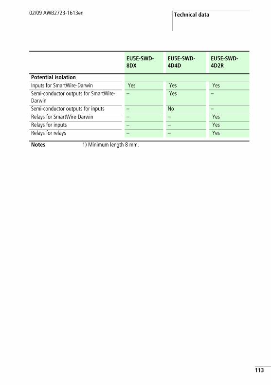
Technical data02/09 AWB2723-1613en
Potential isolationInputs for SmartWire-Darwin Yes Yes YesSemi-conductor outputs for SmartWire-Darwin
– Yes –
Semi-conductor outputs for inputs – No –Relays for SmartWire-Darwin – – YesRelays for inputs – – YesRelays for relays – – Yes
Notes 1) Minimum length 8 mm.
EU5E-SWD-8DX
EU5E-SWD-4D4D
EU5E-SWD-4D2R
113

Appendix
114
02/09 AWB2723-1613en
M22
-SW
D c
onne
ctio
ns
M22
-SW
D-K
11/
M22
-SW
D-K
C11
M22
-SW
D-L
ED-…
/M
22-S
WD
-LED
C-…
M22
-SW
D-K
11LE
D-…
/M
22-S
WD
-K11
LED
C-…
M22
-SW
D-K
22/
M22
-SW
D-K
C22
M22
-SW
D-K
22LE
D-…
/M
22-S
WD
-K22
LED
C-…
Gen
eral
Stan
dard
sIE
C/EN
611
31-2
, EN
501
78Di
men
sions
(W x
H x
D)
mm
12 X
42 X
39/
12 X
45 X
37
10 X
42 X
45/
10 X
45 X
42
12 X
42 X
45/
12 X
45 X
42
17 X
42 X
39/
17 X
45 X
37
17 X
42 X
45/
17 X
45 X
42
Wei
ght
g10
1010
1414
Mou
ntin
g po
sitio
nan
y
Am
bien
t m
echa
nica
l con
diti
ons
Prot
ectio
n ty
pe (I
EC/E
N 6
0529
)IP
20IP
20IP
20IP
20IP
20Vi
brat
ions
(IEC
/EN
611
31-2
:200
8)co
nsta
nt a
mpl
itude
3.5
m
mHz
5 …
8.4
5 …
8.4
5 …
8.4
5 …
8.4
5 …
8.4
cons
tant
acc
eler
atio
n 1
gHz
8.4
… 1
508.
4 …
150
8.4
… 1
508.
4 …
150
8.4
… 1
50
Mec
hani
cal s
hock
resis
tanc
e (IE
C/EN
600
68-2
-27)
se
mi-s
inus
oida
l 15
g/11
ms
Shoc
ks9
99
99
Drop
(IEC
/EN
600
68-2
-31)
; dr
op h
eigh
t m
m50
5050
5050
Free
fall,
pac
kage
d (IE
C/EN
60
068-
2-32
)m
0.3
0.3
0.3
0.3
0.3

Technical data02/09 AWB2723-1613en
Elec
trom
agne
tic
com
pati
bilit
y (E
MC)
Ove
rvol
tage
cat
egor
yN
ot a
pplic
able
Pollu
tion
degr
ee2
22
22
Elec
trost
atic
disc
harg
e (IE
C/EN
611
31-
2:20
08)
Air d
ischa
rge
(Lev
el 3
) k
V8
88
88
Cont
act d
ischa
rge
(Lev
el
2) k
V4
44
44
Elec
trom
agne
tic fi
elds
(IEC
/EN
611
31-
2:20
08)
80-1
000
MHz
V/m
1010
1010
101.
4 - 2
GHz
V/m
33
33
32
- 2.7
GHz
V/m
11
11
1Ra
dio
inte
rfere
nce
supp
ress
ion
(Sm
artW
ire-D
arw
in)
EN 5
5011
Cla
ss A
Burs
t (IE
C/EN
611
31-2
:200
8, L
evel
3)
Supp
ly c
able
s k
V2
22
22
Smar
tWire
-Dar
win
ca
bles
kV
11
11
1
Radi
ated
RFI
(IEC
/EN
61
131-
2:20
08, L
evel
3)
V10
1010
1010
M22
-SW
D-K
11/
M22
-SW
D-K
C11
M22
-SW
D-L
ED-…
/M
22-S
WD
-LED
C-…
M22
-SW
D-K
11LE
D-…
/M
22-S
WD
-K11
LED
C-…
M22
-SW
D-K
22/
M22
-SW
D-K
C22
M22
-SW
D-K
22LE
D-…
/M
22-S
WD
-K22
LED
C-…
115

Appendix
116
02/09 AWB2723-1613en
Am
bien
t cl
imat
ic c
ondi
tion
s
Ope
ratin
g am
bien
t te
mpe
ratu
re (I
EC 6
0068
-2)
°C
–30
… +
55–3
0 …
+55
–30
… +
55–3
0 …
+55
–30
… +
55
Cond
ensa
tion
prev
ent w
ith s
uita
ble
mea
sure
s St
orag
e °
C–4
0…80
–40…
80–4
0…80
–40…
80–4
0…80
Rela
tive
hum
idity
, non
-co
nden
sing
(IEC/
EN 6
0068
-2-
30)
%9
… 9
59
… 9
59
… 9
55
… 9
55
… 9
5
Smar
tWir
e-D
arw
in
netw
ork
Stat
ion
type
Smar
tWire
-Dar
win
sta
tion
(sla
ve)
Baud
rate
set
ting
auto
mat
icSm
artW
ire-D
arw
in s
tatu
s LE
DG
reen
Conn
ectio
nsPl
ug, 8
-pol
ePl
ug c
onne
ctor
sSW
D4-8
SF2-
5/M
22-S
WD-
I…LP
SWD4
-8SF
2-5/
M22
-SW
D-I…
LPSW
D4-8
SF2-
5/M
22-S
WD-
I…LP
SWD4
-8SF
2-5/
M22
-SW
D-I…
LP
SWD4
-8SF
2-5/
M22
-SW
D-I…
LP
Num
ber o
f ins
ertio
n cy
cles
5050
5050
50Cu
rrent
con
sum
ptio
n (1
5 V
SWD
supp
ly)
apa
ge10
3
M22
-SW
D-K
11/
M22
-SW
D-K
C11
M22
-SW
D-L
ED-…
/M
22-S
WD
-LED
C-…
M22
-SW
D-K
11LE
D-…
/M
22-S
WD
-K11
LED
C-…
M22
-SW
D-K
22/
M22
-SW
D-K
C22
M22
-SW
D-K
22LE
D-…
/M
22-S
WD
-K22
LED
C-…
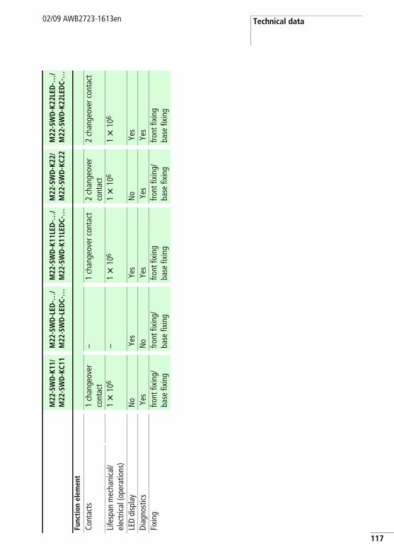
Technical data02/09 AWB2723-1613en
Func
tion
ele
men
t
Cont
acts
1
chan
geov
er
cont
act
–1
chan
geov
er c
onta
ct2
chan
geov
er
cont
act
2 ch
ange
over
con
tact
Life
span
mec
hani
cal/
elec
trica
l (op
erat
ions
)1 X
106
–1 X
106
1 X
106
1 X
106
LED
disp
lay
No
Yes
Yes
No
Yes
Diag
nost
ics
Yes
No
Yes
Yes
Yes
Fixi
ngfro
nt fi
/ba
se fi
front
fixi
ng/
base
fixi
ngfro
nt fi
base
fixi
ngfro
nt fi
/ba
se fi
front
fixi
ngba
se fi
M22
-SW
D-K
11/
M22
-SW
D-K
C11
M22
-SW
D-L
ED-…
/M
22-S
WD
-LED
C-…
M22
-SW
D-K
11LE
D-…
/M
22-S
WD
-K11
LED
C-…
M22
-SW
D-K
22/
M22
-SW
D-K
C22
M22
-SW
D-K
22LE
D-…
/M
22-S
WD
-K22
LED
C-…
117
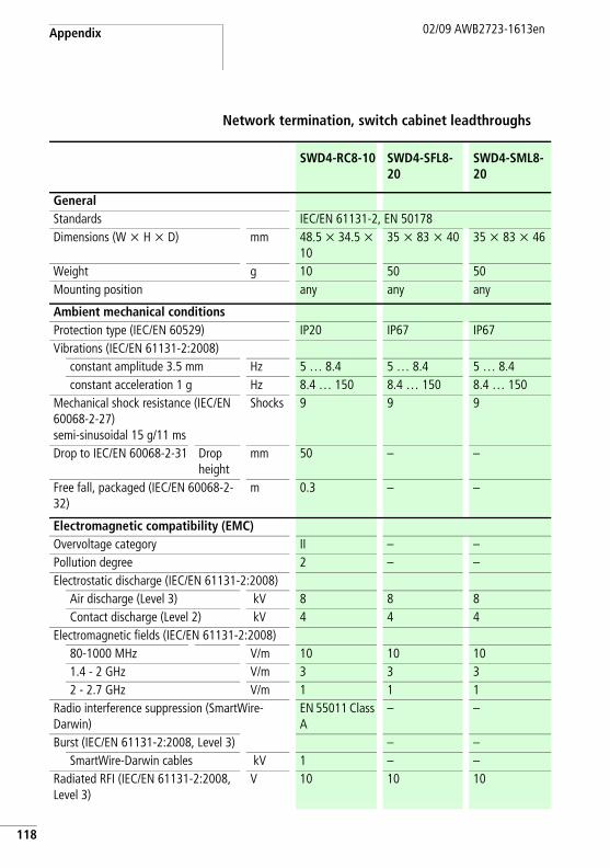
Appendix
118
02/09 AWB2723-1613en
Network termination, switch cabinet leadthroughs
SWD4-RC8-10 SWD4-SFL8-20
SWD4-SML8-20
GeneralStandards IEC/EN 61131-2, EN 50178Dimensions (W x H x D) mm 48.5 x 34.5 x
1035 x 83 x 40 35 x 83 x 46
Weight g 10 50 50Mounting position any any any
Ambient mechanical conditionsProtection type (IEC/EN 60529) IP20 IP67 IP67Vibrations (IEC/EN 61131-2:2008)
constant amplitude 3.5 mm Hz 5 … 8.4 5 … 8.4 5 … 8.4constant acceleration 1 g Hz 8.4 … 150 8.4 … 150 8.4 … 150
Mechanical shock resistance (IEC/EN 60068-2-27) semi-sinusoidal 15 g/11 ms
Shocks 9 9 9
Drop to IEC/EN 60068-2-31 Drop height
mm 50 – –
Free fall, packaged (IEC/EN 60068-2-32)
m 0.3 – –
Electromagnetic compatibility (EMC)Overvoltage category II – –Pollution degree 2 – –Electrostatic discharge (IEC/EN 61131-2:2008)
Air discharge (Level 3) kV 8 8 8Contact discharge (Level 2) kV 4 4 4
Electromagnetic fields (IEC/EN 61131-2:2008)80-1000 MHz V/m 10 10 101.4 - 2 GHz V/m 3 3 32 - 2.7 GHz V/m 1 1 1
Radio interference suppression (SmartWire-Darwin)
EN 55011 Class A
– –
Burst (IEC/EN 61131-2:2008, Level 3) – –SmartWire-Darwin cables kV 1 – –
Radiated RFI (IEC/EN 61131-2:2008, Level 3)
V 10 10 10

Technical data02/09 AWB2723-1613en
Ambient climatic conditionsOperating ambient temperature (IEC 60068-2)
°C –25 … +55 –25 … +55 –25 … +55
Condensation prevent with suitable measures Storage °C –40…70 –40…70 –40…70relative humidity, no condensation(IEC/EN-60068-2-30)
% 5 … 95 5 … 95 5 … 95
Connection optionsSWD-In Socket, 8-pole Plug, 8-pole Plug, 8-poleNumber of insertion cycles ≥ 200 ≥ 200 ≥ 500SWD-Out – Socket, 8-pole Socket, 8-poleNumber of insertion cycles – ≥ 500 ≥ 200Current consumption (15 V SWD supply) a page 103
SWD4-RC8-10 SWD4-SFL8-20
SWD4-SML8-20
119

Appendix
120
02/09 AWB2723-1613en
Enclosure bushings plug, socket
SWD4-SF8-20 SWD4-SM8-20
GeneralStandards IEC/EN 61131-2
EN 50178IEC/EN 61131-2EN 50178
Dimensions (W x H x D) mm 24 x 26 x 162 24 x 26 x 170Weight g 20 22.5Mounting position any any
Ambient mechanical conditionsProtection type (IEC/EN 60529) IP67 IP67
Ambient climatic conditionsOperating ambient temperature (IEC 60068-2) °C –25 … +55 –25 … +55Condensation prevent with suitable measures Storage °C –40…70 –40…70Relative humidity, non-condensing (IEC/EN 60068-2-30)
% 5 … 95 5 … 95
Connection optionsSWD-In – Plug, 8-poleNumber of insertion cycles – ≥ 500SWD-Out Socket, 8-pole –Number of insertion cycles ≥ 500 –Current consumption (15 V SWD supply) a page 103

Technical data02/09 AWB2723-1613en
Coupling, plug
SWD4-8SFF2-5
SWD4-8SF2-5
SWD4-8FRF-10
GeneralStandards IEC/EN 61131-2, EN 50178Dimensions (W x H x D) mm 48.5 x 34.5
x 1015 x 36.5 x 17.5
35 x 90 x 35
Weight g 4.5 5.5 42Mounting position any any any
Ambient mechanical conditionsProtection type (IEC/EN 60529) IP20 IP20 IP20Vibrations (IEC/EN 61131-2:2008)
constant amplitude 3.5 mm Hz 5 … 8.4 5 … 8.4 5 … 8.4constant acceleration 1 g Hz 8.4 … 150 8.4 … 150 8.4 … 150
Mechanical shock resistance (IEC/EN 60068-2-27) semi-sinusoidal 15 g/11 ms
Shocks 9 9 9
Electromagnetic compatibility (EMC)Electrostatic discharge (IEC/EN 61131-2:2008)
Air discharge (Level 3) kV 8 – –Contact discharge (Level 2) kV 4 – –
Ambient climatic conditionsOperating ambient temperature (IEC 60068-2)
°C –25 … +55 –25 … +55 –25 … +55
Condensation prevent with suitable measures
Storage °C –40…70 –40…70 –40…70Relative humidity, non-condensing (IEC/EN 60068-2-30)
% 5 … 95 5 … 95 5 … 95
Connection optionsSWD-In Plug, 8-pole Plug
connectorPlug, 8-pole
Number of insertion cycles ≥ 200 1 ≥ 200SWD-Out Plug, 8-pole Socket, 8-
polePush in terminals
Number of insertion cycles ≥ 200 ≥ 200 –
Current consumption (15 V SWD supply) a page 103
121

Appendix
122
02/09 AWB2723-1613en
DIL contactor modules
DIL-SWD-32-001 DIL-SWD-32-002
GeneralStandards IEC/EN 61131-2, EN 50178, IEC/EN
60947Dimensions (W x H x D) mm 45 X 38 X 76 45 X 38 X 76Weight kg 0.04 0.04Mounting on DILM7 … DILM38Mounting position as DILM7 … DILM38
Ambient mechanical conditionsProtection type (IEC/EN 60529) IP20 IP20Vibrations (IEC/EN 61131-2:2008)
constant amplitude 3.5 mm Hz 5 … 8.4 5 … 8.4constant acceleration 1 g Hz 8.4 … 150 8.4 … 150
Mechanical shock resistance (IEC/EN 60068-2-27) semi-sinusoidal 15 g/11 ms
Shocks 9 9
Drop to IEC/EN 60068-2-31 Drop height
mm 50 50
Free fall, packaged (IEC/EN 60068-2-32) m 0.3 0.3
Electromagnetic compatibility (EMC)Overvoltage category II IIPollution degree 2 2Electrostatic discharge (IEC/EN 61131-2:2008)
Air discharge (Level 3) kV 8 8Contact discharge (Level 2) kV 4 4
Electromagnetic fields (IEC/EN 61131-2:2008)80-1000 MHz V/m 10 101.4 - 2 GHz V/m 3 32 - 2.7 GHz V/m 1 1
Radio interference suppression (SmartWire-Darwin) EN 55011 Class A EN 55011 Class ABurst (IEC/EN 61131-2:2008, Level 3)
CAN/DP bus cable kV 1 1SmartWire-Darwin cables kV 1 1
Radiated RFI (IEC/EN 61131-2:2008, Level 3) 10 10

Technical data02/09 AWB2723-1613en
Ambient climatic conditionsOperating ambient temperature (IEC 60068-2) °C –25 … +60 –25 … +60Condensation prevent with suitable measures Storage °C –30…70 –30…70Relative humidity, non-condensing (IEC/EN 60068-2-30)
% 5 … 95 5 … 95
SmartWire-Darwin networkStation type SmartWire-Darwin station (slave)Baud rate setting automaticSmartWire-Darwin status LED
yellowgreen/orange
Connections Plug, 8-polePlug connectors External device plug SWD4-8SF2-5Current consumption (15 V SWD supply) a page 103
Mode parameterManual/automatic mode No YesSetting – Rotary switch
Connection auxiliary contactNumber 2 2Rated voltage1) Ue V DC 15 15Input current at 1 signal, typical m A 3 3Potential isolation No NoCable length m F2.8 F2.8Connection type Push-In Push-In
Terminal capacitysolid mm 2 0.2 - 1.5 (AWG 24 - 16)flexible with ferrule2) mm 2 0.25 - 1.5 0.25 - 1.5
Notes 1) Own supply. 2) Minimum length 8 mm.
DIL-SWD-32-001 DIL-SWD-32-002
123

124
02/09 AWB2723-1613en

02/09 AWB2723-1613en
Index
A Applicationssafety-related ...............................................44
Auxiliary contactenable ..........................................................36
Auxiliary contact block ........................................31
C Cable protection ..................................................14Contactor coils
power consumption ......................................34Contactor voltage ..................................................8Coupling contactor ..............................................33Current carrying capacity
maximum (North America) ...........................50
D Device statusSmartWire-Darwin slaves ............23, 55, 69, 91
Diagnostics messages ....................................23, 55DOL Starters ..................................................36, 51
E EMC Protection ...................................................12EN 62061 ............................................................50EN 954-1 .............................................................47EN ISO 13849-1 ..................................................50
F Feedback circuit ..................................................47Ferrule ...................................................................9
H Holding current ...................................................34
125

Index 02/09 AWB2723-1613en
126
M M22 front elementPossibilities of combiningwith SWD elements ......................................65
Mirror contact .....................................................47Mounting
On top-hat rail ...............................................9
N NFPA 79 .............................................................50North America
Application ..................................................50
P PELV ...................................................................44Pick-up current ....................................................34Pick-up power .....................................................34Protection against polarity reversal ......................12
R Reversing starters ................................................51RMQ-Titan-System ..............................................61
S Safety categories .................................................47Safety switch-off
selective .........................................................8Sealing power .....................................................34Supply voltage connection ...............................8, 12SWD-Assist ...................................................66, 86
T Terminations ...................................................9, 13Total Power Consumption .................19, 34, 66, 86