1 basic design of the ship - marinedocs · 1 basic design of the ship chapter outline ... 6 ship...
TRANSCRIPT


1 Basic design of the ship
Chapter OutlinePreparation of the design 3Information provided by design 4Purchase of a new vessel 6Ship contracts 7Further reading 8Some useful websites 9
The key requirement of a new ship is that it can trade profitably, so economics is ofprime importance in designing a merchant ship. An owner requires a ship that willgive the best possible returns for the owner’s initial investment and running costs. Thefinal design should be arrived at taking into account not only present economicconsiderations, but also those likely to develop within the life of the ship. This isespecially the case for some trades, for example LNG, where the ship is expected towork the same route for its working life. Design for operation is the result. For otherships, including bulk carriers, the first cost of the ship is the major factor for the ownerand the ship may be designed for ease of production. Resale value is also oftena major consideration, leading to design for maintenance.
With the aid of computers it is possible to make a study of a large number ofvarying design parameters and to arrive at a ship design that is not only technicallyfeasible but, more importantly, is the most economically efficient. Ideally the designwill take into consideration first cost, operating cost, and future maintenance.
Preparation of the design
The initial design of a ship generally proceeds through three stages: concept;preliminary; and contract design. The process of initial design is often illustrated bythe design spiral (Figure 1.1), which indicates that given the objectives of the design,the designer works towards the best solution adjusting and balancing the interrelatedparameters as the designer goes.
A concept design should, from the objectives, provide sufficient information fora basic techno-economic assessment of the alternatives to be made. Economic criteriathat may be derived for commercial ship designs and used to measure their profit-ability are net present value, discounted cash flow, or required freight rate.
Ship Construction. DOI: 10.1016/B978-0-08-097239-8.00001-5
Copyright � 2012 Elsevier Ltd. All rights reserved.

Preliminary design refines and analyzes the agreed concept design, fills out thearrangements and structure, and aims to optimize service performance. At this stagethe builder should have sufficient information to tender. Contract design details thefinal arrangements and systems agreed with the owner and satisfies the buildingcontract conditions.
The design of the ship is not complete at this stage, rather for the major effort inresources it has only just started. Post-contract design requires confirmation that theship will meet all operational requirements, including safety requirements fromregulators. It also entails in particular design for production where the structure,outfit, and systems are planned in detail to achieve a cost- and time-effective buildingcycle. Production of the ship must also be given consideration in the earlier designstages, particularly where it places constraints on the design or can affect costs. Thepost-contract design will also ideally consider the future maintainability of the ship inthe arrangement of equipment and services.
Information provided by design
When the preliminary design has been selected the following information is available:
l Dimensionsl Displacementl Stability
Conceptdesign
Preliminarydesign
Contractdesign
Capacities
Weightestimate
Powering
Structure
Generalarrangements
Freeboardand subdivision
Hydrostatics
Lines
Proportions
Vesselobjectives
Costestimate
Stability
Figure 1.1 Design spiral.
4 Ship Construction

l Propulsive characteristics and hull forml Preliminary general arrangementl Principal structural details.
Each item of information may be considered in more detail, together with anyrestraints placed on these items by the ship’s service or other factors outside thedesigner’s control.
1. The dimensions of most ships are primarily influenced by the cargo-carryingcapacity of the vessel. In the case of the passenger vessel, dimensions are influencedby the height and length of superstructure containing the accommodation. Length,where not specified as a maximum, should be a minimum consistent with the requiredspeed and hull form. Increase of length produces higher longitudinal bending stressesrequiring additional strengthening and a greater displacement for the same cargoweight. Breadth may be such as to provide adequate transverse stability. A minimumdepth is controlled by the draft plus statutory freeboard, but an increase in depth willresult in a reduction of the longitudinal bending stresses, providing an increase instrength, or allowing a reduction in scantlings (i.e. plate thickness/size of stiffeningmembers etc.). Increased depth is therefore preferred to increased length. Draft isoften limited by area of operation, but if it can be increased to give a greater depth thiscan be an advantage.
Many vessels are required to make passages through various canals and straits andpass under bridges within enclosed waters, and this will place a limitation on theirdimensions. For example, locks in the Panama Canal and St Lawrence Seaway limitlength, breadth, and draft. At the time of writing, the Malacca Straits main shippingchannel is about 25 meters deep and the Suez Canal could accommodate ships witha beam of up to 75 meters and maximum draft of 16 metres. A maximum air draft oncontainer ships of around 40 meters is very close to clear the heights of the GerardDesmond Bridge, Long Beach, California and Bayonne Bridge, New York. Newerbridges over the Suez Canal at 65 meters and over the Bosporus at 62 meters providegreater clearance.
2. Displacement is made up of lightweight plus deadweight. The lightweight is theweight of vessel as built and ready for sea. Deadweight is the difference between thelightweight and loaded displacement, i.e. it is the weight of cargo plus weights of fuel,stores, water ballast, fresh water, crew and passengers, and baggage. When carryinghigh-density cargoes (e.g. ore) it is desirable to keep the lightweight as small aspossible, consistent with adequate strength. Since only cargo weight of the totaldeadweight is earning capital, other items should be kept to a minimum as long as thevessel fulfills its commitments.
3. In determining the dimensions, statical stability is kept in mind in order toensure that this is sufficient in all possible conditions of loading. Beam and depth arethe main influences. Statutory freeboard and sheer are important together with theweight distribution in arranging the vessel’s layout.
4. Adequate propulsive performance will ensure that the vessel attains the requiredspeeds. The hull form is such that economically it offers a minimum resistance tomotion so that a minimum power with economically lightest machinery is installedwithout losing the specified cargo capacity.
Basic design of the ship 5

A service speed is the average speed at sea with normal service power and loadingunder average weather conditions. A trial speed is the average speed obtained usingthe maximum power over a measured course in calm weather with a clean hull andspecified load condition. This speed may be a knot or so more than the service speed.
Unless a hull form similar to that of a known performance vessel is used,a computer-generated hull form and its predicted propulsive performance can bedetermined. The propulsive performance can be confirmed by subsequent tank testingof a model hull, which may suggest further beneficial modifications.
The owner may specify the type and make of main propulsion machinery instal-lation with which their operating personnel are familiar.
5. The general arrangement is prepared in cooperation with the owner, allowingfor standards of accommodation particular to that company, also specific cargo andstowage requirements. Efficient working of the vessel must be kept in mindthroughout and compliance with the regulations of the various authorities involved ontrade routes must also be taken into account. Some consultation with shipboardemployees’ representative organizations may also be necessary in the final accom-modation arrangements.
6. Almost all vessels will be built to the requirements of a classification societysuch as Lloyd’s Register. The standard of classification specified will determine thestructural scantlings and these will be taken out by the shipbuilder. The determinationof the minimum hull structural scantlings can be carried out by means of computerprograms made available to the shipyard by the classification society. Owners mayspecify thicknesses and material requirements in excess of those required by theclassification societies and special structural features peculiar to the trade or owner’sfleet may be asked for.
Purchase of a new vessel
In recent years the practice of owners commissioning ‘one-off’ designs for cargoships from consultant naval architects, shipyards, or their own technical staff hasincreasingly given way to the selection of an appropriate ‘stock design’ to suit theirparticular needs. To determine which stock design, the shipowner must undertakea detailed project analysis involving consideration of the proposed market, route, portfacilities, competition, political and labor factors, and cash flow projections. Alsotaken into account will be the choice of shipbuilder, where relevant factors such as theprovision of government subsidies or grants or supplier credit can be important aswell as the price, date of delivery, and the yard’s reputation. Most stock designs offersome features that can be modified, such as outfit, cargo handling equipment, oralternate manufacture of main engine, for which the owner will have to pay extra.
Purchase of a passenger vessel will still follow earlier procedures for a ‘one-off’design, but there are shipyards concentrating on this type of construction and the ownermay be drawn to them for this reason. A nonstandard cargo ship of any form anda number of specialist ships will also require a ‘one-off’ design. Having decided on thebasic ship requirements, based on the intended trade, after an appropriate project
6 Ship Construction
analysis the larger shipowners may employ their own technical staff to prepare thetender specification and submit this to shipbuilders who wish to tender for the buildingof the ship. The final building specification and design is prepared by the successfultendering shipbuilder in cooperation with the owner’s technical staff. The latter mayoversee construction of the vessel and approve the builder’s drawings and calculations.Other shipowners may retain a firm of consultants or approach a firm who may assistwith preliminary design studies and will prepare the tender specifications and in somecases call tenders on behalf of the owner. Often the consultants will also assist theowners in evaluating the tenders and oversee the construction on their behalf.
Ship contracts
The successful tendering shipbuilder will prepare a building specification forapproval by the owner or the owner’s representative that will form an integral part ofthe contract between the two parties and thus have legal status. This technicalspecification will normally include the following information:
l Brief description and essential qualities and characteristics of the shipl Principal dimensionsl Deadweight, cargo and tank capacities, etc.l Speed and power requirementsl Stability requirementsl Quality and standard of workmanshipl Survey and certificatesl Accommodation detailsl Trial conditionsl Equipment and fittingsl Machinery details, including the electrical installation, will normally be produced as
a separate section of the specification.
Most shipbuilding contracts are based on one of a number of standard forms ofcontract that have been established to obtain some uniformity in the contract rela-tionship between builders and purchasers. There are a number of ‘standard’ contractforms, all very similar in structure and content. Four of the most common standardforms of contract have been established by:
1. CESA—Community of European Shipyards Associations2. MARAD Maritime Administration, USA3. SAJ—Shipbuilders Association of Japan4. Norwegian Shipbuilding Contract—Norwegian Shipbuilders Association and Norwegian
Shipowners Association.
The CESA standard form of contract was developed by the predecessor organization,the Association of Western European Shipyards (AWES).The contract form can bedownloaded from the CESA website. The sections of the contract are:
1. Subject of contract (vessel details, etc.)2. Inspection and approval
Basic design of the ship 7
3. Modifications4. Trials5. Guarantee (speed, capacity, fuel consumption)6. Delivery of vessel7. Price8. Property (rights to specifications, plans, etc. and to vessel during construction and on
delivery)9. Insurance
10. Default by the purchaser11. Default by the contractor12. Guarantee (after delivery)13. Contract expenses14. Patents15. Interpretation, reference to expert and arbitration16. Condition for the contract to become effective17. Legal domicile (of purchaser and contractor)18. Assignment (transfer of rights)19. Limitation of liability20. Addresses for correspondence.
Irrespective of the source of the owner’s funds for purchasing the ship, payment to theshipbuilder is usually made as progress payments that are stipulated in the contractunder item 7 above. A typical payment schedule may have been five equal paymentsspread over the contract period, but in recent years payment arrangements advanta-geous to the purchaser and intended to attract buyers to the shipyard have delayeda higher percentage of payment until delivery of the ship. The payment schedule maybe as follows:
l 10% on signing contractl 10% on arrival of materials on sitel 10% on keel layingl 20% on launchingl 50% on delivery.
Because many cargo ships are of a standard design, and built in series, and modi-fication can be very disruptive to the shipyard building program, item 3 in thestandard form of contract where modifications are called for at a late date by theowner can have a dramatic effect on costs and delivery date given the detail nowintroduced at an early stage of the fabrication process. Many shipyards will refuse toaccept modifications once a design is agreed and detailed work and purchasingcommences. Item 3 also covers the costs and delays of compulsory modificationsresulting from amendment of laws, rules, and regulations of the flag state andclassification society.
Further reading
Rawson, Tupper: Basic Ship Theory. ed 5, vol 2. Chapter 15: Ship design, 2001, ButterworthHeinemann.
8 Ship Construction

Watson DGM: Practical Ship Design, 2002, Elsevier.
Some useful websites
www.cesa.eu Community of European Shipyards Associations.www.sajn.or.jp/e Shipbuilders Association of Japan; provides links to member shipyard sites.
Basic design of the ship 9

2 Ship dimensions, form, size, orcategory
Chapter OutlineOil tankers 13Bulk carriers 13Container ships 15IMO oil tanker categories 15Panama canal limits 15Suez canal limits 16Some useful websites 16
The hull form of a ship may be defined by a number of dimensions and terms that areoften referred to during and after building the vessel. An explanation of the principalterms is given below:
After Perpendicular (AP): A perpendicular drawn to the waterline at the point where theafter side of the rudder post meets the summer load line. Where no rudder post is fitted it istaken as the center line of the rudder stock.Forward Perpendicular (FP): A perpendicular drawn to the waterline at the point where thefore-side of the stem meets the summer load line.Length Between Perpendiculars (LBP): The length between the forward and aft perpen-diculars measured along the summer load line.Amidships: A point midway between the after and forward perpendiculars.Length Overall (LOA): Length of vessel taken over all extremities.Lloyd’s Length: Used for obtaining scantlings if the vessel is classed with Lloyd’s Register.It is the same as length between perpendiculars except that it must not be less than 96% andneed not be more than 97% of the extreme length on the summer load line. If the ship has anunusual stem or stern arrangement the length is given special consideration.Register Length: The length of ship measured from the fore-side of the head of the stem tothe aft side of the head of the stern post or, in the case of a ship not having a stern post, to thefore-side of the rudder stock. If the ship does not have a stern post or a rudder stock, the afterterminal is taken to the aftermost part of the transom or stern of the ship. This length is theofficial length in the register of ships maintained by the flag state and appears on officialdocuments relating to ownership and other matters concerning the business of the ship.Another important length measurement is what might be referred to as the IMO Length. Thislength is found in various international conventions such as the Load Line, Tonnage,SOLAS and MARPOL conventions, and determines the application of requirements ofthose conventions to a ship. It is defined as 96% of the total length on a waterline at 85% of
Ship Construction. DOI: 10.1016/B978-0-08-097239-8.00002-7
Copyright � 2012 Elsevier Ltd. All rights reserved.
the least molded depth measured from the top of keel, or the length from the fore-side ofstem to the axis of rudder stock on that waterline, if that is greater. In ships designed witha rake of keel the waterline on which this length is measured is taken parallel to the designwaterline.
Molded dimensions are often referred to; these are taken to the inside of plating ona metal ship.
Base Line: A horizontal line drawn at the top of the keel plate. All vertical moldeddimensions are measured relative to this line.Molded Beam: Measured at the midship section, this is the maximum molded breadth of theship.Molded Draft: Measured from the base line to the summer load line at the midship section.Molded Depth: Measured from the base line to the heel of the upper deck beam at the ship’sside amidships.Extreme Beam: The maximum beam taken over all extremities.Extreme Draft: Taken from the lowest point of keel to the summer load line. Draft marksrepresent extreme drafts.Extreme Depth: Depth of vessel at ship’s side from upper deck to lowest point of keel.Half Breadth: Since a ship’s hull is symmetrical about the longitudinal centre line, oftenonly the half beam or half breadth at any section is given.Freeboard: The vertical distance measured at the ship’s side between the summer load line(or service draft) and the freeboard deck. The freeboard deck is normally the uppermostcomplete deck exposed to weather and sea that has permanent means of closing all open-ings, and below which all openings in the ship’s side have watertight closings.Sheer: A rise in the height of the deck (curvature or in a straight line) in the longitudinaldirection. Measured as the height of deck at side at any point above the height of deck at sideamidships.Camber (or Round of Beam): Curvature of decks in the transverse direction. Measured as theheight of deck at center above the height of deck at side. Straight line camber is used onmany large ships to simplify construction.Rise of Floor (or Deadrise): The rise of the bottom shell plating line above the base line.This rise is measured at the line of molded beam. Large cargo ships often have no rise offloor.Half Siding of Keel: The horizontal flat portion of the bottom shell measured to port orstarboard of the ship’s longitudinal center line. This is a useful dimension to know when dry-docking.Tumblehome: The inward curvature of the side shell above the summer load line. This isunusual on modern ships.Flare: The outward curvature of the side shell above the waterline. It promotes dryness andis therefore associated with the fore end of ship.Stem Rake: Inclination of the stem line from the vertical.Keel Rake: Inclination of the keel line from the horizontal. Trawlers and tugs often havekeels raked aft to give greater depth aft where the propeller diameter is proportionatelylarger in this type of vessel. Small craft occasionally have forward rake of keel to bringpropellers above the line of keel.Tween Deck Height: Vertical distance between adjacent decks measured from the tops ofdeck beams at ship’s side.Parallel Middle Body: The length over which the midship section remains constant in areaand shape.
12 Ship Construction

Entrance: The immersed body of the vessel forward of the parallel middle body.Run: The immersed body of the vessel aft of the parallel middle body.Tonnage: This is often referred to when the size of the vessel is discussed, and the grosstonnage is quoted from Lloyd’s Register. Tonnage is a measure of the enclosed internalvolume of the vessel (originally computed as 100 cubic feet per ton). This is dealt with indetail in Chapter 30.Deadweight: This is defined in Chapter 1. It should be noted that for tankers deadweight isoften quoted in ‘long tons’ rather than ‘metric tons (tonnes)’; however, MARPOL regula-tions for oil tankers are in metric tons.
The principal dimensions of the ship are illustrated in Figure 2.1.
TEU and FEU: Indicate the cargo-carrying capacity of container ships. TEU (twenty-footequivalent unit) indicates the number of standard shipping containers that may be carried onsome shipping routes; container ships may carry standard containers that are 40 feet inlength. FEU is forty-foot equivalent unit.
An indication of the size by capacity of oil tankers, bulk carriers, and container shipsis often given by the following types:
Oil tankersl ULCC (Ultra-Large Crude Carrier) is a tanker usually between 300,000 and 550,000 tonnes
deadweight.l VLCC (Very Large Crude Carrier) is a tanker usually between 200,000 tonnes and 300,000
tonnes deadweight.l Suezmax indicates the largest oil tanker that can transit the current Suez Canal fully laden,
being about 150,000 tonnes deadweight.l Aframax the standard designation of smaller crude oil tankers, being the largest tanker size
in the AFRA Freight Rate Assessment Scale Large One Category. AFRA stands for‘American Freight Rate Association’. Variously reported as being 80,000 to 115,000 tonesdeadweight.
l Panamax is the maximum size of oil tanker, with beam restriction of 32.2 meters and lengthrestriction of 275 meters, that can transit the Panama Canal prior to completion of theplanned new locks. Typical size is about 55,000–70,000 tonnes deadweight.
l Handysize/Handymax are typical product tankers of about 35,000–45,000 tonnesdeadweight.
Bulk carriersl Capesize ships that are too large to transit the current Panama Canal and therefore voyage
around Cape Horn. All bulk carriers above 80,000 tonnes deadweight fall into this category.Most are up to 170,000 tonnes deadweight but a small number are larger for specific traderoutes, the biggest being 365,000 tonnes deadweight.
l Panamax—As for oil tankers.l Handymax ships are between around 35,000 and 60,000 tonnes deadweight.l Ships between 10,000 and 35,000 tonnes deadweight have formed the majority of the fleet
for many years and are designated ‘Handysize’. In recent years the size of these ships hasbeen increasing and the term ‘Handymax’ has been applied to designate the larger bulkcarriers.
Ship dimensions, form, size, or category 13

Sheer aft Sheer forward
FreeboardSummer load line
Length between perpendiculars (LBP)Length on waterline (LWL)
Length overall (LOA)
Amidships
Camber
Draft
Depth
Base line
Half siding of keel
Rise of floor
Tumblehome
Aftperpendicular
Fordperpendicular
Molded beam
Figure 2.1 Principal ship dimensions.
14
Ship
Constru
ction
Container shipsl Ultra-large container ships. Ships with a capacity of over 14,000 TEU. Few have been built
to date. These ships are too large for any canals.l Post-Panamax ships are too large to transit the current Panama Canal and undertake trans-
ocean voyages. Their size is typically 5500–8000 TEU though larger ships with over 10,000TEU capacity have been built.
l New Panamax ships (including most Post-Panamax ships) would be able to transit theexpanded Panama Canal. They may carry up to around 12,000 TEU.
l Panamax ships that can transit the current Panama Canal carry between 3000 and 5000TEU.
l Feeder ships are smaller vessels that do not undertake oceanic voyages but are generallyengaged in shipping containers. The smallest of these may only carry several hundred TEU.There is no specific subclass below Panamax size.
IMO oil tanker categoriesl Category 1 (commonly known as Pre-MARPOL tankers) includes oil tankers of 20,000
tonnes deadweight and above carrying crude oil, fuel oil, heavy diesel oil, or lubricating oilas cargo, and of 30,000 tonnes deadweight and above carrying other oils, which do notcomply with the requirements for protectively located segregated ballast tanks. These shipshave been phased out under IMO regulations.
l Category 2 (commonly known as MARPOL tankers) includes oil tankers of 20,000 tonnesdeadweight and above carrying crude oil, fuel oil, or lubricating oil as cargo, and of30,000 tonnes deadweight and above carrying other oils, which do comply with theprotectively located segregated ballast tank requirements. These ships are due to bephased out.
l Category 3 includes oil tankers of 5000 tonnes deadweight and above but less than thetonnes deadweight specified for Categories 1 and 2. Also due to be phased out.
Note: For tankers carrying HGO (heavy gas oil) the lower limits for Categories 2 and3 fall to 600 tonnes deadweight.
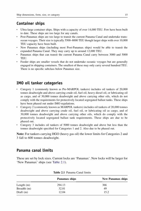
Panama canal limits
These are set by lock sizes. Current locks are ‘Panamax’. New locks will be larger for‘New Panamax’ ships (see Table 2.1).
Table 2.1 Panama Canal limits
Panamax ships New Panamax ships
Length (m) 294.13 366Breadth (m) 32.81 49Draft (m) 12.04 15.2
Ship dimensions, form, size, or category 15

Suez canal limits
There are no locks and ship size is limited by the canal dimensions. There isa maximum breadth limit of 75 meters. With no locks the ship length is also unre-stricted. The maximum draft is 20 meters.
The Saint Lawrence Seaway links the North American Great Lakes to theAtlantic. The limits for ships based on the locks are length 226 m, breadth 24 m, anddraft 7.92 m.
Some useful websites
www.pancanal.com/eng/general For details of Panama Canal.http://www.suezcanal.gov.eghttp://www.greatlakes-seaway.com
16 Ship Construction
3 Development of ship types
Chapter OutlineDry cargo ships 17
Container ships 21Barge-carrying ships 21Ro-ro ships 21Hull form 23Cargo handling equipment 23
Bulk carriers 23Car carriers 26Oil tankers 26Passenger ships 30Further reading 33
A breakdown into broad working groups of the various types that the shipbuilder orship designer might be concerned with are shown in Figure 3.1. This covers a widerange and reflects the adaptability of the shipbuilding industry. It is obviously notpossible to cover the construction of all those types in a single volume. The devel-opment of the vessels with which the text is primarily concerned, namely dry cargoships (including container ships and dry bulk carriers), tankers (oil, liquid gas andchemical) and passenger ships, follows.
Dry cargo ships
If the development of the dry cargo ship from the time of introduction of steam pro-pulsion is considered, the pattern of change is similar to that shown in Figure 3.2. Thefirst steam ships followed in most respects the design of the sailing ship, having a flushdeck with the machinery openings protected only by low coamings and glass skylights.At quite an early stage it was decided to protect the machinery openings with anenclosed bridge structure. Erections forming a forecastle and poopwere also introducedat the forward and after respectively for protection. This resulted in what is popularlyknown as the ‘three island type’. A number of designs at that time also combined bridgeand poop, and a few combined bridge and forecastle, so that a single well was formed.
Another form of erection introduced was the raised quarter deck. Raised quarterdecks were often associated with smaller deadweight carrying vessels, e.g. colliers.
Ship Construction. DOI: 10.1016/B978-0-08-097239-8.00003-9
Copyright � 2012 Elsevier Ltd. All rights reserved.

High speedcraft Off shore
oil vesselsFishingvessels
Harbor/oceanwork craft
Drycargoships
Liquidcargo ships
Passengerships
Submersibles Warships
Multi-hullsIncludingwave piercers
Small waterplanearea, twin-hull(SWATH)
Surface effect(SES) and
Hovercraftship
Hydrofoil
Wing in groundeffect craft(WIG)
Supply ship
Pipelayers
Cranebarges
Semi-submersibledrill rigs
Drill ships
Accommodationbarges
Production platforms
Floating storageunit (FSU)
Floating productionand storage unit
(FPSO)
Trawlerspurse seiners
etc.
Factoryships
TugsCablelayers
Floatingdry docks
Dredgers
Salvage/buoy vessels
Tenders
Pilot craft
Floatingcranes
Lightships
Tramps Oil tankers
Bulkcarriers
Cargoliners
Containervessels
Barge carriers
Ro-ro ships
Refrigerated cargoships
Timber carriers
Livestock carriers
Car carriers
Liquefied gascarriers
Chemicalcarriers
Liners
Cruiseships
Emigrantand pilgrim
ships (STP s)’
Cross-channelferries
Coastalferries
Harborferries
Figure 3.1 Ship types.
18
Ship
Constru
ction
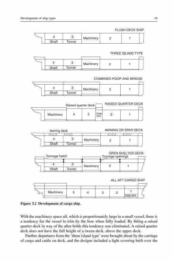
With the machinery space aft, which is proportionately large in a small vessel, there isa tendency for the vessel to trim by the bow when fully loaded. By fitting a raisedquarter deck in way of the after holds this tendency was eliminated. A raised quarterdeck does not have the full height of a tween deck, above the upper deck.
Further departures from the ‘three island type’ were brought about by the carriageof cargo and cattle on deck, and the designs included a light covering built over the
FLUSH DECK SHIP
4
Shaft Tunnel
3 2 1Machinery
RAISED QUARTER DECKRaised quarter deck
Machinery 4 3 2 1Deeptank
4
Shaft Tunnel
3 2 1Machinery
AWNING OR SPAR DECKAwning deck
Machinery 4 35 2 1Deep tank
ALL AFT CARGO SHIP
4
Shaft Tunnel
3 2 1Machinery
Tonnage hatch Tonnage openingsOPEN SHELTER DECK
THREE ISLAND TYPE
4
Shaft Tunnel
3 2 1Machinery
4
Shaft Tunnel
3 2 1Machinery
COMBINED POOP AND BRIDGE
Figure 3.2 Development of cargo ship.
Development of ship types 19

wells for the protection of these cargoes. This resulted in the awning or spar deck typeof ship, the temporary enclosed spaces being exempt from tonnage measurementsince they were not permanently closed spaces. These awning or spar deck structureseventually became an integral part of the ship structure but retained a lighter structurethan the upper deck structure of other two-deck ships, later referred to as ‘fullscantling’ vessels. The ‘shelter deck type’, as this form of vessel became known, apartfrom having a lighter upper structure was to have the freeboard measured from thesecond deck, and the tween deck space was exempt from tonnage measurement. Thisexemption was obtained by the provision of openings in the shelter deck and tweendeck bulkheads complying with certain statutory regulations.
At a later date, what were known as open/closed shelter deck ships were devel-oped. These were full scantling ships having the prescribed openings so that the tweendeck was exempt from tonnage measurement when the vessel was operating at a loaddraft where the freeboard was measured from the second deck. It was possible to closepermanently these temporary openings and reassign the freeboard, it then beingmeasured from the upper deck so that the vessel might load to a deeper draft, and thetween deck was no longer exempt from tonnage measurement.
Open shelter deck vessels were popular with shipowners for a long period.However, during that time much consideration was given to their safety and theundesirable form of temporary openings in the main hull structure. Eliminating theseopenings without substantially altering the tonnage values was the object of muchdiscussion and deliberation. Finally, Tonnage Regulations introduced in 1966provided for the assignment of a tonnage mark, at a stipulated distance below thesecond deck. A vessel having a ‘modified tonnage’ had tonnage measured to thesecond deck only, i.e. the tween deck was exempt, but the tonnage mark was not to besubmerged. Where a vessel was assigned ‘alternative tonnages’ (the equivalent ofprevious open/closed shelter deck ship), tonnage was taken as that to the second deckwhen the tonnage mark was not submerged. When the tonnage mark was submerged,tonnage was taken as that to the upper deck, the freeboard being a minimummeasuredfrom the upper deck. The tonnage mark concept effectively dispensed with theundesirable tonnage openings. Further changes to tonnage requirements in 1969 led tothe universal system of tonnage measurement without the need for tonnage marks,although older ships did retain their original tonnages up until 1994 (see Chapter 30).
Originally the machinery position was amidships with paddle wheel propulsion.Also, with coal being burnt as the propulsive fuel, bunkers were then favorably placedamidships for trim purposes. With the use of oil fuel this problem was more or lessovercome, and with screw propulsion there are definite advantages in having themachinery aft. Taking the machinery right aft can produce an excessive trim by thestern in the light condition and the vessel is then provided with deep tanks forward.This may lead to a large bending moment in the ballast condition, and a compromiseis often reached by placing the machinery three-quarters aft. That is, there are saythree or four holds forward and one aft of the machinery space. In either arrangementthe amidships portion with its better stowage shape is reserved for cargo, and shaftspaces lost to cargo are reduced. The all-aft cargo ship illustrating the final evolutionof the dry cargo ship in Figure 3.2 could represent the sophisticated cargo liners of the
20 Ship Construction

mid 1960s. By the mid 1970s many of the cargo liner trades had been taken over bythe container ship and much of the short haul trade undertaken by the conventionaldry cargo ship had passed to the ‘roll-on roll-off’ (ro-ro) type of vessel.
Container ships
A feature of the container ship is the stowage of the rectangular container units withinthe fuller rectangular portion of the hull and their arrangement in tiers above the maindeck level. In order to facilitate removal and placing of the container units of inter-nationally agreed standard (ISO) dimensions hold and hatch widths are common. Thenarrow deck width outboard of the hatch opening forms the crown of a double shellspace containing wing ballast tanks and passageways (see Figure 17.9). Latercontainer ship designs feature hatchless vessels that provide a faster turnaround inport. These may have hatch covers on the forward holds only, or none at all, and areprovided with substantial stripping pumps for removing rain and green water from theholds. In recent years the size of container ships making oceanic voyages hassubstantially increased. The largest ships are those operated by Maersk, which cancarry a reported 13,500 TEU. These are unusual and most large ships are betweenwith one classification society reporting more than 60 vessels of at least 8000 TEUclassed (see Figure 3.3b).
Barge-carrying ships
Another development in the cargo liner trade was the introduction of the barge-carrying vessel. An early version of this type of ship had a particular advantage inmaintaining a scheduled service between the ports at mouths of large river systemssuch as between the Mississippi river in the USA and the Rhine in Europe. Standardunit cargo barges (sometimes referred to as LASH—lighter aboard ship—barges) arecarried on board ship and placed overboard or lifted onboard at terminal ports by largedeck-mounted gantries or elevator platforms in association with traveling rails. Otherdesigns make provision for floating the barges in and out of the carrying ship, whichcan be ballasted to accommodate them. This development appears not to have been assuccessful as was initially envisaged in the late 1970s, and whilst the merits of thistype of craft are still often referred to, the type is now rarely seen.
Ro-ro ships
These ships are characterized by the stern and in some cases the bow or side doorsgiving access to a vehicle deck above the waterline but below the upper deck (seeFigure 3.3a). Access within the ship may be provided in the form of ramps or liftsleading from this vehicle deck to upper decks or hold below. Ro-ro ships may be fittedwith various patent ramps for loading through the shell doors when not trading toregular ports where link span and other shore-side facilities that are designed to suitare available. Cargo is carried in vehicles and trailers or in unitized form loaded byfork-lift and other trucks. In order to permit the drive-through vehicle deck
Development of ship types 21

(b)
(a)
Main deck
Upper deck
Ramps
ER Hold
Lift
Tween
Angled stern ramp
Stern door
ER
Vessel has adjustable internal ramp giving access to decks
Weather deck
Main deck Hold
Figure 3.3 (a) Roll-on roll-off ships. (b) 7700 TEU container ship.
22
Ship
Constru
ction

a restriction is placed on the height of the machinery space and the ro-ro ship wasamong the first to popularize the geared medium-speed diesel engine with a lesserheight than its slow-speed counterpart. The dramatic loss of the ro-ro passenger shipsHerald of Free Enterprise in 1987 and Estonia in 1994 saw much attention directed atthe damage stability of this type of passenger ship when water entered the openunsubdivided deck space. This has resulted in international regulation requiring,amongst other things, strengthening and surveillance of bow doors, surveillance ofinternal watertight doors used at sea, enhanced damage stability criteria (SOLAS 90)and additional simplified stability information for the master. The Estonia loss led tofurther stringent damage stability requirements adopted on a regional basis bynorthern European countries (Stockholm Agreement 1997). A midship section ofa ro-ro passenger/vehicle/train ferry complying with the requirements of the latteragreement is shown in Figure 17.10.
Hull form
Between the 1940s and 1970 there was a steady increase in the speed of the dry cargoship and this was reflected in the hull form of the vessels. A much finer hull isapparent in modern vessels, particularly in those ships engaged in the longer cargoliner trades. Bulbous bow forms and open water sterns are used to advantage andconsiderable flare may be seen in the bows of container ships to reduce wetness ondeck where containers are stowed. In some early container ships it is thought that thiswas probably overdone, leading to an undesirable tendency for the main hull to whipduring periods when the bows pitched into head seas. Larger container ships may havethe house three-quarters aft with the full beam maintained right to the stern to give thelargest possible container capacity.
Cargo handling equipment
Cargo handling equipment, which remained relatively unchanged for a long period, hasreceived considerable attention since the 1960s. This was primarily brought about by anawareness of the loss of revenue caused by the long periods of time the vesselmay spendin port discharging and loading cargoes. Conventional cargo ships are now fitted withsteel folding and/or rolling steel hatch covers of one patent type or another or liftableslab covers of steel, which reduce maintenance as well as speed cargo handling. Variousnew lifting devices, derrick forms, andwinches have been designed and introducedwithmarine shipborne cranes now almost completely replacing rigged derrick installationson modern ships. These provide further increased rates of loading and discharge.
Bulk carriers
Awide range of bulk commodities are carried in bulk carriers, including coal, grain,ore, cement, alumina, bauxite, and mineral sand plus shipments of products such aspackaged steel and timber.
Development of ship types 23

The large bulk carrier originated as an ore carrier on the Great Lakes at thebeginning of the twentieth century. For the period of the Second World War dedicatedbulk carriers were only built spasmodically for ocean trading, since a large amount ofthese cargoes could be carried by general cargo tramps with the advantage of theirbeing able to take return cargoes.
A series of turret-deck steamers were built for ore-carrying purposes between 1904and 1910; a section through such a vessel is illustrated in Figure 3.4a. Since 1945a substantial number of ocean-going ore carriers have been built of uniform design.This form of ore carrier with a double bottom and side ballast tanks first appeared in1917, only at that time the side tanks did not extend to the full hold depth (seeFigure 3.4b). To overcome the disadvantage that the ore carrier was only usefullyemployed on one leg of the voyage, the oil/ore carrier also evolved at that time. Thelatter ship type carried oil in the wing tanks, as shown in Figure 3.4c, and hada passageway for crew protection in order to obtain the deeper draft permitted tankers.
The common general bulk carrier that predominated in the latter half of thetwentieth century took the form shown in Figure 3.4d with double bottom, hoppersides, and deck wing tanks. These latter tanks have been used for the carriage of lightgrain cargoes as well as water ballast. Specific variations of this type have been built;Figure 3.4e shows a ‘universal bulk carrier’ patented by the McGregor InternationalOrganization that offered a very flexible range of cargo stowage solutions. Anothertype, shown in Figure 3.4f, had alternate holds of short length. On single voyages thevessel could carry high-density cargoes only in the short holds to give an acceptablecargo distribution. Such stowage is not uncommon on general bulk carriers withuniform hold lengths where alternate hold loading or block hold loading may beutilized to stow high-density cargoes. With such loading arrangements high shearforces occur at the ends of the holds, requiring additional strengthening of the sideshell in way of the bulkheads.
A general arrangement of a typical bulk carrier shows a clear deck with machineryaft. Large hatches with steel covers are designed to facilitate rapid loading anddischarge of the cargo. Since the bulk carrier makes many voyages in ballast, a largeballast capacity is provided to give adequate immersion of the propeller. The size ofthis type of ship has also steadily increased and the largest bulk carriers have reached365,000 tonnes deadweight.
Ships of the general bulk carrier form experienced a relatively high casualty rateduring the late 1980s and early 1990s (between 1980 and 2000 some 170 bulk carrierswere totally lost), giving rise to concern as to their design and construction.Throughout the late 1990s bulk carrier safety received considerable attention in thework of IMO, the classification societies and elsewhere. Based on experience offailures of lesser consequence, it was concluded that the casualties occurred throughlocal structural failure leading to loss of watertight integrity of the side shell, followedby progressive flooding through damaged bulkheads. The flooding resulted either inexcessive hull bending stresses or excessive trim, and loss of the ship. Much of thiswork concentrated on the structural hull details, stresses experienced as the result ofloading and discharging cargoes (past experience showed that ships were often loadedin patterns not approved in the ship’s loading manual), damage to structure and
24 Ship Construction

(a) TURRET TYPE ORECARRIER 1910
Waterballast
(b) ORE CARRIER
Passageway
Double bottom
Ore
Ore
Double bottom
OreOil Oil
Passageway
(c) ORE/OIL CARRIER
Waterballast Ore
(d) GENERAL BULK CARRIER
Double bottom
Cargo
Machinery
Machinery
65
5
9
44
5OreOre 7 3
33
Ore Ore 1
11
22
(e) UNIVERSAL BULK CARRIER(shown carrying ore)
(f) GENERAL CARGO SHIP WITH SHORT HOLDS FOR ORE
Ore
Water ballastor grain
Figure 3.4 Bulk carriers.
Develo
pmentofship
types
25

protective coatings arising from discharging cargoes, poor maintenance, and subse-quent inadequate inspection of the ship structure. The initial outcome of this workwas the introduction of a new Chapter XII of SOLAS covering damage stabilityrequirements, structural strength requirements, and enhanced survey procedures forbulk carriers. At its 79th session in December 2004, the Maritime Safety Committeeof IMO adopted a new text of Chapter XII of SOLAS that included restrictions onsailing with any hold empty and requirements for double-skin construction as anoptional alternative to single side-skin construction. The option of double side-skinconstruction applies only to new bulk carriers of 150 meters or more in length,carrying solid bulk cargoes having a density of 1000 kg/m3 and above. Theseamendments entered into force on 1 July 2006. The midship section of a Handysizebulk carrier with double-skin construction is shown in Figure 17.8.
Car carriers
The increasing volume of car and truck production in the East (Japan, Korea, andChina) and a large customer base in the West has seen the introduction and rapidincrease in the number of ships specifically designed and built to facilitate thedelivery of these vehicles globally.
Probably the ugliest ships afloat, car carriers are strictly functional, having a veryhigh boxlike form above the waterline to accommodate as many vehicles as possibleon, in some cases, as many as a dozen decks. Whilst most deck spacing is to suit cars,some tween deck heights may be greater and the deck strengthened to permit loadingof higher and heavier vehicles. Within such greater deck spacing liftable car decksmay be fitted for flexibility of stowage. The spacing of fixed car decks can vary from1.85 to 2.3 meters to accommodate varying shapes and heights of cars. Transferarrangements for vehicles from the main deck are by means of hoistable ramps,which can be lifted and lowered whilst bearing the vehicles. Loading and dis-charging vehicles onto and off the ship is via a large quarter ramp at the stern anda side shell or stern ramp. The crew accommodation and forward wheelhouse,providing an adequate view forward, sit atop the uppermost continuous weatherdeck. Propulsion machinery is situated aft with bow thruster(s) forward to aidmooring/maneuvering.
The ship shown in Figure 3.5 has an overall length of 148 meters, a beam of25 meters, and a speed of 19 knots on a 7.2-meter draft. It can carry some 2140 units.A unit is an overall stowage area of 8.5 square meters per car and represents a vehicle4.125 meters in length and 1.55 meters wide plus an all-round stowage margin.
Oil tankers
Until 1990 the form of vessels specifically designed for the carriage of oil cargoes hadnot undergone a great deal of change since 1880, when the vessel illustrated in
26 Ship Construction

Deck No. 4
BRIDGEACCOMDT.
DECKS
QUARTER RAMP
3,2DOWN
UP 5,4
STERN RAMP
87654321
Figure 3.5 Car carrier.
Develo
pmentofship
types
27

Figure 3.6a was constructed, the expansion trunk and double bottom within the cargospace having been eliminated much earlier. The greatest changes in that period werethe growth in ship size and nature of the structure (see Figure 3.6b).
The growth in size of ocean-going vessels from 1880 to the end of the SecondWorld War was gradual, the average deadweight rising from 1500 tonnes to about12,000 tonnes. Since then the average deadweight increased rapidly to about 20,000tonnes in 1953 and about 30,000 tonnes in 1959. Today there are afloat tankersranging from 100,000 to 500,000 tonnes deadweight. It should be made clear that thelarger size of vessel is the crude oil carrier, and fuel oil carriers tend to remain withinthe smaller deadweights.
Service speeds of oil tankers have shown an increase since the late 1940s, goingfrom 12 to 17 knots. The service speed is related to the optimum economic operationof the tanker. Also, the optimum size of the tanker is very much related to currentmarket economics. The tanker fleet growth increased enormously to meet theexpanding demand for oil until 1973/1974, when the OPEC price increases slowedthat expansion and led to a slump in the tanker market. It is unlikely that sucha significant rise in tanker size and rise in speed will be experienced in the foreseeablefuture.
Structurally, one of the greatest developments has been in the use of welding, oiltankers being amongst the first vessels to utilize the application of welding. Little
Length 77.6 mBeamDepth 5.8 m
Deadweight 1680 tonnes
Speed 10 k
Expansion trunk
Wing tank Center tank Wing tank
Double bottom
(a)
Length B.P. 330 mBeam 53.3 mDepth 32 m
Deadweight 332,000 tonnes
Speed 14½ k
Center tanktank tank
WingWing
(b)
DOUBLE-HULL TANKER
SB
T
SB
T
SB
T
SB
T
SBT SBT SBT
Centertank
tank tank
Wing Wing
MID-DECK TANKER PRINCIPLE
SBT SBTOil
Oil
Oil
Oil
Mid-deck
10.4 m
Figure 3.6 Oil tankers.
28 Ship Construction

difficulty is experienced in making and maintaining oiltight joints: the same cannot besaid of riveting. Welding has also allowed cheaper fabrication methods to be adopted.Longitudinal framing was adopted at an early date for the larger ships and revision ofthe construction rules in the late 1960s allowed the length of tank spaces to beincreased, with a subsequent reduction in steel weight, making it easier to pumpdischarge cargoes.
As far as the general arrangement is concerned, there appears always to have beena trend towards placing the machinery aft. Moving all the accommodation and bridgeaft was a later feature and is desirable from the fire protection point of view. Locationof the accommodation in one area is more economic from a building point of view,since all services are only to be provided at a single location.
The requirements of the International Convention for the Prevention of Pollutionfrom Ships 1973 (see Chapter 29) and particularly its Protocol of 1978 have greatlyinfluenced the arrangement of the cargo spaces of oil tankers. A major feature of theMARPOL Convention and its Protocol has been the provision in larger tankers ofclean water ballast capacity. Whilst primarily intended to reduce the pollution risk,the fitting of segregated water ballast tanks in the midship region aids the reduction ofthe still water bending moment when the tanker is fully loaded. It also reducescorrosion problems associated with tank spaces, which are subject to alternate oil andsea water ballast cargoes.
In March 1989 the tanker Exxon Valdez, which complied fully with the then currentMARPOL requirements, ran aground and discharged 11 million gallons of crude oilinto the pristine waters of Prince William Sound in Alaska. The subsequent publicoutcry led to the United States Congress passing the Oil Pollution Act 1990 (OPA 90).This unilateral action by the United States government made it a requirement thatexisting single-hull oil tankers operating in United States waters were to be phasedout by an early date, after which all oil tankers were to have a double hull (see Figures3.6 and 22.2).
In November 1990 the USA suggested that the MARPOL Convention should beamended to make double hulls compulsory for new tankers. A number of otherIMO member states suggested that alternative designs offering equivalent protec-tion against accidental oil spills should be accepted. In particular, Japan proposedan alternative, the mid-deck tanker. This design has side ballast tanks providingprotection against collision but no double bottom. The cargo tank space (seeFigure 3.6) had a structural deck running its full length at about 0.25–0.5 the depthfrom the bottom, which ensures that should the bottom be ruptured the upwardpressure exerted by the sea would prevent most of the oil from escaping intothe sea.
In 1992 IMO adopted amendments to MARPOL that required tankers of 5000tonnes deadweight and above contracted for after July 1993, or which commencedconstruction after January 1994, to be of double-hulled or mid-deck construction, orof other design offering equivalent protection against oil pollution. Existing tankerswith single hulls without segregated ballast tanks with protective location were to bephased out by June 2007. Those with segregated ballast tanks with protective locationwere to be phased out by July 2021.
Development of ship types 29

Studies by IMO and the US National Academy of Sciences confirmed the effec-tiveness of the double hull in preventing oil spills caused by grounding and collisionwhere the inner hull is not breached. The mid-deck tanker was shown to have morefavorable outflow performance in extreme accidents where the inner hull is breached.The United States authorities considered grounding the most prevalent type ofaccident in their waters and believed only the double-hull type prevented spills fromtanker groundings in all but the most severe incidents. Thus, whilst MARPOLprovided for the acceptance of alternative tanker designs, the United States legislationdid not, and no alternative designs were built.
As the result of the break-up of the tanker Erika and subsequent pollution of theFrench coastline in 1999, IMOmembers decided to accelerate the phase-out of single-hull tankers. As a result, in April 2001 a stricter timetable for the phasing out ofsingle-hull tankers entered into force in September 2003. In December 2003 a deci-sion to further accelerate the phase-out dates of single-hull tankers was agreed, Pre-MARPOL tankers being phased out in 2005 and MARPOL tankers and small tankersin 2010 (see Chapter 2 for definitions).
Oil tankers now generally have a single pump space aft, adjacent to the machinery,and specified slop tanks into which tank washings and oily residues are pumped. Tankcleaning may be accomplished by water-driven rotating machines on the smallertankers but for new crude oil tankers of 20,000 tonnes deadweight and above the tankcleaning system uses crude oil washing.
Passenger ships
Early passenger ships did not have the tiers of superstructure associated withmodern vessels, and they also had a narrower beam in relation to their length. Thereason for the absence of superstructure decks was the Merchant Shipping Act1894, which limited the number of passengers carried on the upper deck. Anamendment to this Act in 1906 removed this restriction and vessels were then builtwith several tiers of superstructures. This produced problems of strength andstability, stability being improved by an increase in beam. The transmissionof stresses to the superstructure from the main hull girder created much differenceof opinion as to the means of overcoming the problem. Both light structures ofa discontinuous nature, i.e. fitted with expansion joints, and superstructures with-heavier scantlings able to contribute to the strength of the main hull girderwere introduced. Present practice, where the length of the superstructure isappreciable and has its sides at the ship side, does not require the fitting ofexpansion joints.
The introduction of aluminum alloy superstructures provided increased passengeraccommodation on the same draft, and/or a lowering of the lightweight center ofgravity with improved stability. This was brought about by the lighter weight of thealuminum alloy structure. Subsequent experience, however, has shown that forpassenger liners, that are required to maintain a service speed in a seaway, themaintenance costs of aluminum alloy superstructures can be higher.
30 Ship Construction

A feature of the general arrangement is the reduction in size of the machineryspace in this time. It is easy to see the reason for this if the Aquitania, built in 1914 andhaving direct drive turbines with 21 double-ended scotch boilers, is compared withthe Queen Elizabeth 2. The latter as originally built had geared drive turbines withthree water tube boilers. Many modern passenger ships have had their machineryplaced aft; this gives over the best part of the vessel amidships entirely to passengeraccommodation. Against this advantage, however, allowance must be made for anincreased bending moment if a suitable trim is to be obtained. The more recentprovision of electric podded propulsors as fitted on the Queen Mary 2 has, with theremoval of shaft lines, permitted optimization of the internal arrangements of thepassenger liner and cruise ship.
Passenger accommodation standards have increased substantially, the volume ofspace allotted per passenger rising steadily. Tween deck clearances are greater andpublic rooms extend through two or more decks, whilst enclosed promenade andatrium spaces are now common in these vessels. The provision of air-conditioningand stabilizing devices has also added to passenger comfort. Particular attention hasbeen paid to fire safety in the modern passenger ship, structural materials of low firerisk being utilized in association with automatic extinguishing and detectionsystems.
There has been a demise of the larger passenger liner and larger passenger shipsare now either cruise ships, short-haul ferries, or special trade passenger (STP) ships,the latter being unberthed immigrant or pilgrim passenger ships operating in theMiddle East to South East Asian region.
Whilst the safety of passenger ships in general has been good in recent years, thegrowth in the size and number of cruise ships has led IMO to initiate a review ofpassenger ship safety. In particular, it is looking at placing greater emphasis on theprevention of a casualty from occurring in the first place. That is, future passengerships should be designed for improved survivability so that in the event of a casualtypassengers and crew can stay safely on board as the ship proceeds to port.
The development of high-speed passenger ferries of lightweight construction andoften of radical hull form and/or nondisplacement modes of operation has beennotable since the early 1980s. Initially relatively small, these craft may now be morethan 100 meters in length and carry upwards of 500 persons plus 100 cars/30 trucks ormore. The lightweight construction is usually of aluminum alloy but some have beenconstructed of lighter higher-tensile steels, and fiber-reinforced plastics may be usedin the superstructure and accommodation areas. With speeds of up to 50 knots, manycraft are of twin-hull form and include conventional catamarans, wave piercers withtwin hulls and a faired buoyant bridging structure forward, and small waterplanetwin-hulled (SWATH) ships. The latter have a high proportion of their twin-hullbuoyancy below the waterline (see Figure 3.7). Other high-speed craft includehydrofoils and various surface effect ships (SESs) including hovercraft, whichmaintain a cushion of air, fully or partially, between the hull and the water to reducedrag. The increasing use of these vessels led in 1994 to the promulgation by IMO ofspecific international regulations concerning their design, safety, and operation. Anupdated version of this Code of Safety was adopted in December 2000. Figure 3.7
Development of ship types 31

egdirB
yrenihcaM
noitadommoccA
kced elciheV
NARAMATAC GNICREIP EVAW
TPECNOC HTAWSNARAMATAC LLUH-ITLUMLIOFORDYH
Figure 3.7 Various types of high-speed craft.
32
Ship
Constru
ction
illustrates the various types of high-speed craft. Also see Figure 17.11, which showsthe midship section of a high-speed wave-piercing catamaran.
Further reading
Barge carriers—A revolution in marine transport, The Naval Architect, April 1973.Bhave, Roy G: Special trade passenger ships, The Naval Architect, January 1975.Burrows: The North Sea platform supply vessel, ImarEST Trans. Part 1, 1997.Code of Safety for Special Purpose Ships. IMO publication (IMO-820E).Design and operation of bulk carriers. 2005 Conference Proceedings. Royal Institution of
Naval Architects Publications.Design and operation of container ships. 2003 Conference Proceedings. Royal Institution of
Naval Architects Publications.Design and operation of double hull tankers. 2004 Conference Proceedings. Royal Institution
of Naval Architects Publications.Design and operation of gas carriers. 2004 Conference Proceedings. Royal Institution of Naval
Architects Publications.Farell: Chemical tankers—The quiet evolution, The Naval Architect, July 1975.Guidelines for the Design and Construction of Offshore Supply Vessels. IMO publication
(IMO-807E).Guidelines on Early Assessment of Hull Damage and Possible Need for Abandonment of Bulk
Carriers. IMO—MSC/Circ. 1143 dated 13 December 2004.High speed craft. 2004 Conference Proceedings. Royal Institution of Naval Architects
Publications.IMO: International Code of Safety for High Speed Craft (HSC Code), 1994.Meek: The first OCL container ship, Trans. RINA, 1970.Modern car ferry design and development, The Naval Architect, January 1980.Murray: Merchant ships 1860–1960, Trans. RINA, 1960.Payne: The evolution of the modern cruise liner, The Naval Architect, 1990.Payne: From Tropicale to Fantasy: A decade of cruiseship development, Trans. RINA, 1993.Payne: The return of the true liner—A design critique of the modern fast cruise ship, The
Naval Architect, September 1994.Safety of passenger ro-ro vessels. 1996 Conference Proceedings. Royal Institution of Naval
Architects Publications.
Development of ship types 33

4 Classification societies
Chapter OutlineRules and regulations 38Lloyd’s register 38
Lloyd’s register classification symbols 39Classification of ships operating in ice 40Structural design programs 40Periodical surveys 41
Annual surveys 41Intermediate surveys 41Docking surveys 41In-water surveys 42Special surveys 42
Hull planned maintenance scheme 43Damage repairs 43Further reading 43Some useful websites 43
A cargo shipper and the underwriter requested to insure a maritime risk requiresome assurance that any particular vessel is structurally fit to undertake a proposedvoyage. To enable the shipper and underwriter to distinguish the good risk from thebad, a system of classification has been formulated over a period of more than 200years. During this period reliable organizations have been created for the initialand continuing inspection of ships so that classification may be assessed andmaintained.
Recent amendment to the requirements of the International Convention for theSafety of Life at Sea (SOLAS—see Chapter 29) have required ships to which thatconvention applies to be designed, constructed, and maintained in compliance withthe structural, mechanical, and electrical requirements of a classification society thatis recognized by the flag administration or with applicable national standards of thatadministration that provide an equivalent level of safety. In general, flag adminis-trations recognize specific classification societies for this purpose rather than main-taining such national standards.
Whilst there are reported to be more than 50 ship classification organizationsworldwide, the 13 major classification societies that claim to class over 90% of allcommercial tonnage involved in international trade worldwide are members of the
Ship Construction. DOI: 10.1016/B978-0-08-097239-8.00004-0
Copyright � 2012 Elsevier Ltd. All rights reserved.
International Association of Classification Societies (IACS). These members of theIACS are:
American Bureau of Shipping (ABS) USABureau Veritas (BV) FranceChina Classification Society (CCS) ChinaCroatian Register of Shipping CroatiaDet Norske Veritas (DNV) NorwayGermanischer Lloyd (GL) GermanyIndian Register of Shipping IndiaKorean Register (KR) KoreaLloyd’s Register (LR) Great BritainNippon Kaiji Kyokai (Class NK) JapanPolish Register of Shipping PolandRegistro Italiano Navale (RINA) ItalyRussian Maritime Register of Shipping (RS) Russia
Rules and regulations
The classification societies each publish rules and regulations that are principallyconcerned with the strength and structural integrity of the ship, the provision ofadequate equipment, and the reliability of the machinery. Ships may be built in anycountry to a particular classification society’s rules and they are not restricted toclassification by the relevant society of the country where they are built or owned.
In recent years, under the auspices of the IACS, member societies have beenengaged in the development of common structural rules for ships. The first two ofthese common structural rules, for bulk carriers of 90 meters or more in length and foroil tankers of 150 meters or more in length came into force on 1 April 2006. Thesecommon rules will be incorporated into each member society’s rule book. InNovember 2008 the IACS launched the IACS CSR Tracking Database (www.iacs-csrtrack.org.uk) to provide users easy and quick access to full revision history ofCSR rules on a paragraph by paragraph basis.
These and other common rules to be developed by IAC members anticipate thenature of future standards to be made under the International Maritime Organization’sproposed Goal-Based New Ship Construction Standards (see Chapter 29).
Lloyd’s register
Only the requirements of Lloyd’s Register, which is the oldest of the classificationsocieties, are dealt with in detail in this chapter. The requirements of other classifi-cation societies that are members of the IACS are not greatly different.
Founded in 1760 and reconstituted in 1834, Lloyd’s Register was amalgamatedwith the British Corporation, the only other British classification society in existence
38 Ship Construction

at that time, in 1949. Ships built in accordance with Lloyd’s Register rules orequivalent standards are assigned a class in the Register Book, and continue to beclassed so long as they are maintained in accordance with the rules.
Lloyd’s register classification symbols
All ships classed by Lloyd’s Register are assigned one or more character symbols.The majority of ships are assigned the characters 100A1 or 100A1.
The character figure 100 is assigned to all ships considered suitable for sea-goingservice. The character letter A is assigned to all ships that are built in accordancewith or accepted into class as complying with the society’s rules and regulations.The character figure 1 is assigned to ships carrying on board anchor and/or mooringequipment complying with the society’s rules and regulations. Ships that the societyagree need not be fitted with anchor and mooring equipment may be assigned thecharacter letter N in lieu of the character figure 1. The Maltese cross mark isassigned to new ships constructed under the society’s special survey, i.e. a surveyorhas been in attendance during the construction period to inspect the materials andworkmanship.
There may be appended to the character symbols, when considered necessary bythe society or requested by the owner, a number of class notations. These classnotations may consist of one or a combination of the following: type notation,cargo notation, special duties notation, special features notation, service restrictionnotation. Type notation indicates that the ship has been constructed in compliancewith particular rules applying to that type of ship, e.g. 100A1 ‘Bulk carrier’. Cargonotation indicates the ship has been designed to carry one or more specific cargoes,e.g. ‘Sulfuric acid’. This does not preclude it from carrying other cargoes for whichit might be suitable. Special duties notation indicates that the ship has beendesigned for special duties other than those implied by type or cargo notation,e.g. ‘research’. Special features notation indicates the ship incorporates specialfeatures that significantly affect the design, e.g. ‘movable decks’. Service restric-tion notation indicates the ship has been classed on the understanding it is operatedonly in a specified area and/or under specified conditions, e.g. ‘Great Lakes andSt Lawrence’.
The class notation LMC indicates that the machinery has been constructed,installed, and tested under the society’s special survey and in accordance with thesociety’s rules and regulations. Various other notations relating to the main andauxiliary machinery may also be assigned.
Vessels with a refrigerated cargo installation constructed, installed, and testedunder the society’s special survey and in accordance with its rules and regulationsmay be assigned the notation Lloyd’s RMC. A classed liquefied gas carrier ortanker in which the cargo reliquefaction or cargo refrigeration equipment is approved,installed, and tested in accordance with the society’s rules and regulations may beassigned the notation Lloyd’s RMC (LG).
Where additional strengthening is fitted for navigation in ice conditions anappropriate notation may be assigned.
Classification societies 39

Classification of ships operating in ice
Classification societies such as Lloyd’s Register and a number of administrationswhose waters experience icing have for many years had regulations defining andcategorizing ice conditions and specifying design and standard requirements for shipsoperating in ice. Lloyd’s Register have assigned special features notations to manyexisting ships for operation in first-year ice and for operation in multi-year ice. First-year ice notations are for additional strengthening where waters ice up in winter onlyand multi-year ice for service in Arctic and Antarctic waters.
The increasing maritime trading within Arctic waters in the past decade and thedesire to ship oil, gas, and other commodities from there all year round appears tohave resulted in the class societies adopting to some extent the ice strengtheningrequirements of the ‘Finnish–Swedish Ice Class Rules 1985’ developed for vesselstrading in winter and for which the keel was laid after 1 November 1986. Theserequirements were intended primarily for vessels operating in the Northern Baltic inwinter are given for four different ice classes:
l Ice Class 1AAl Ice Class 1Al Ice Class 1Bl Ice Class 1C.
The hull scantling requirements determined under these rules are based on certainassumptions concerning the nature of the ice load the ship’s structure may be sub-jected to. These assumptions have been determined from full-scale observations madein the Northern Baltic.
This increased trading in Arctic waters has also created particular interest in theestablishment of universal requirements for ships operating in ice.
Both the IMO and IACS have been involved in this work, with the IMO producingguidelines inDecember 2002 for ships operating inArctic ice-coveredwaters forwhichthey prescribe seven ‘Polar Class’ descriptions. These range from PC 1 for year-roundoperation in all Arctic ice covered waters to PC 7 for summer/autumn operation in thinfirst-year ice that may include old ice inclusions. Subsequently, the IACS set upa working group to develop Unified Requirements for Polar Ships that would cover:
a. Polar class descriptions and applicationsb. Structural requirements for Polar class shipsc. Machinery requirements for Polar class ships.
It was intended that with the completion of these Uniform Requirements for PolarShips and their adoption by the IACS Council, the IACS member societies will haveone year in which to implement these common standards for ships operating in ice.
Structural design programs
In recent years the principal classification societies have developed software packagesfor use by shipyards that incorporate dynamic-based criteria for the scantlings,
40 Ship Construction

structural arrangements, and details of ship structures. This was a response toa perception that the traditional semi-empirical published classification rules based onexperience could be inadequate for new and larger vessel trends. The computerprograms made available to shipyards incorporate a realistic representation of thedynamic loads likely to be experienced by the ship and are used to determine thescantlings and investigate the structural responses of critical areas of the ship’sstructure.
Lloyd’s Register’s ‘Ship Right Procedures for the Design, Construction andLifetime Care of Ships’ incorporates programs for structural design assessment(SDA) and fatigue design assessment (FDA). Also incorporated are constructionmonitoring (CM) procedures that ensure the identified critical locations on the shipare built to acceptable standards and approved construction procedures. (Theseprovisions are mandatory for classification of tankers of more than 190 meters inlength and for other ships where the type, size, and structural configuration demand.)
Periodical surveys
To maintain the assigned class the vessel has to be examined by the society surveyorsat regular periods.
The major hull items to be examined at these surveys only are indicated below.
Annual surveys
All steel ships are required to be surveyed at intervals of approximately one year.These annual surveys are, where practicable, held concurrently with statutory annualor other load-line surveys. At the survey the surveyor is to examine the condition ofall closing appliances covered by the conditions of assignment of minimum free-board, the freeboard marks, and auxiliary steering gear. Watertight doors and otherpenetrations of watertight bulkheads are also examined and the structural fireprotection verified. The general condition of the vessel is assessed, and anchors andcables are inspected where possible at these annual surveys. Dry bulk cargo ships aresubject to an inspection of a forward and after cargo hold.
Intermediate surveys
Instead of the second or third annual survey after building or special survey, anintermediate survey is undertaken. In addition to the requirements for annual survey,particular attention is paid to cargo holds in vessels over 15 years of age and theoperating systems of tankers, chemical carriers, and liquefied gas carriers.
Docking surveys
Ships are to be examined in dry dock at intervals not exceeding 2½ years. At the dry-docking survey particular attention is paid to the shell plating, stern frame and rudder,
Classification societies 41

external and through hull fittings, and all parts of the hull particularly liable tocorrosion and chafing, and any unfairness of bottom.
In-water surveys
The society may accept in-water surveys in lieu of any one of the two dockingsrequired in a five-year period. The in-water survey is to provide the informationnormally obtained for the docking survey. Generally, consideration is only given to anin-water survey where a suitable high-resistance paint has been applied to theunderwater hull.
Special surveys
All steel ships classed with Lloyd’s Register are subject to special surveys. Thesesurveys become due at five-yearly intervals, the first five years from the date of buildor date of special survey for classification and thereafter five years from the date of theprevious special survey. Special surveys may be carried out over an extended periodcommencing not before the fourth anniversary after building or previous specialsurvey, but must be completed by the fifth anniversary.
The hull requirements at a special survey, the details of the compartments to beopened up, and the material to be inspected at any special survey are listed in detail inthe rules and regulations (Part 1, Chapter 3). Special survey hull requirements aredivided into four ship age groups as follows:
1. Special survey of ships—five years old2. Special survey of ships—10 years old3. Special survey of ships—15 years old4. Special survey of ships—20 years old and at every special survey thereafter.
In each case the amount of inspection required increases and more material isremoved so that the condition of the bare steel may be assessed. It should be noted thatwhere the surveyor is allowed to ascertain by drilling or other approved means thethickness of material, nondestructive methods such as ultrasonics are available incontemporary practice for this purpose. Additional special survey requirements areprescribed for oil tankers, dry bulk carriers, chemical carriers, and liquefied gascarriers.
When classification is required for a ship not built under the supervision of thesociety’s surveyors, details of the main scantlings and arrangements of the actual shipare submitted to the society for approval. Also supplied are particulars of manufactureand testing of the materials of construction, together with full details of the equip-ment. Where details are not available, the society’s surveyors are allowed to lift therelevant information from the ship. At the special survey for classification, all the hullrequirements for special surveys (1), (2), and (3) are to be carried out. Ships over20 years old are also to comply with the hull requirements of special survey (4), andoil tankers must comply with the additional requirements stipulated in the rulesand regulations. During this survey, the surveyor assesses the standard of the
42 Ship Construction

workmanship, and verifies the scantlings and arrangements submitted for approval. Itshould be noted that the special survey for classification will receive specialconsideration from Lloyd’s Register in the case of a vessel transferred from anotherrecognized classification society. Periodical surveys where the vessel is classed aresubsequently held as in the case of ships built under survey, being dated from the dateof special survey for classification.
Hull planned maintenance scheme
Along with other classification societies, Lloyd’s Register offers a hull plannedmaintenance scheme (HPMS) that may significantly reduce the scope of the peri-odical surveys of the hull. The classification society works closely with the shipownerto set up an inspection program that integrates classification requirements with theshipowner’s own planned maintenance program. Ship staff trained and accreditedby Lloyd’s Register are authorized to inspect selected structural items according toan approved schedule. Compliance is verified by Lloyd’s Register surveyors at anannual audit.
Damage repairs
When a vessel requires repairs to damaged equipment or to the hull, it is necessary forthe work to be carried out to the satisfaction of Lloyd’s Register surveyors. In orderthat the ship maintains its class, approval of the repairs undertaken must be obtainedfrom the surveyors either at the time of the repair or at the earliest opportunity.
Further reading
Lloyd’s Register, Rules and Regulations for the Classification of Ships, Part 1, Regulations,Chapters 2 and 3.
Some useful websites
www.iacs.org.uk IACS website—see in particular Classification Societies—What, Whyand How?
www.lr.org Lloyd’s Register website.www.eagle.org American Bureau of Shipping website.
Classification societies 43

5 Steels
Chapter OutlineManufacture of steels 46
Open hearth process 46Electric furnaces 46Oxygen process 47Chemical additions to steels 47
Heat treatment of steels 48Annealing 48Normalizing 48Quenching (or hardening) 48Tempering 48Stress relieving 48
Steel sections 48Shipbuilding steels 49High tensile steels 50Corrosion-resistant steels 50Steel sandwich panels 50Steel castings 52Steel forgings 52Further reading 52Some useful websites 52
The production of all steels used for shipbuilding purposes starts with the smeltingof iron ore and the making of pig-iron. Normally the iron ore is smelted in a blastfurnace, which is a large, slightly conical structure lined with a refractory material.To provide the heat for smelting, coke is used and limestone is also added. Thismakes the slag formed by the incombustible impurities in the iron ore fluid, so thatit can be drawn off. Air necessary for combustion is blown in through a ring ofholes near the bottom, and the coke, ore, and limestone are charged into the top ofthe furnace in rotation. Molten metal may be drawn off at intervals from a hole orspout at the bottom of the furnace and run into molds formed in a bed of sandor into metal molds.
The resultant pig-iron contains 92–97% iron, the remainder being carbon, silicon,manganese, sulfur, and phosphorus. In the subsequent manufacture of steels the pig-iron is refined; in other words the impurities are reduced.
Ship Construction. DOI: 10.1016/B978-0-08-097239-8.00005-2
Copyright � 2012 Elsevier Ltd. All rights reserved.

Manufacture of steels
Steels may be broadly considered as alloys of iron and carbon, the carbon percentagevarying from about 0.1% in mild steels to about 1.8% in some hardened steels. Thesemay be produced by one of four different processes: the open hearth process, theBessemer converter process, the electric furnace process, or an oxygen process.Processes may be either an acid or basic process according to the chemical nature ofthe slag produced. Acid processes are used to refine pig-iron low in phosphorus andsulfur that are rich in silicon and therefore produce an acid slag. The furnace lining isconstructed of an acid material so that it will prevent a reaction with the slag. A basicprocess is used to refine pig-iron that is rich in phosphorus and low in silicon.Phosphorus can be removed only by introducing a large amount of lime, whichproduces a basic slag. The furnace lining must then be of a basic refractory to preventa reaction with the slag. About 85% of all steel produced in Britain is of the basictype, and with modern techniques is almost as good as the acid steels produced withsuperior ores.
Only the open hearth, electric furnace, and oxygen processes are described here asthe Bessemer converter process is not used for shipbuilding steels.
Open hearth process
The open hearth furnace is capable of producing large quantities of steel, handling150–300 tonnes in a single melt. It consists of a shallow bath, roofed in, and set abovetwo brick-lined heating chambers. At the ends are openings for heated air and fuel(gas or oil) to be introduced into the furnace. Also, these permit the escape of theburned gas, which is used for heating the air and fuel. Every 20 minutes or so the flowof air and fuel is reversed.
In this process a mixture of pig-iron and steel scrap is melted in the furnace, carbonand the impurities being oxidized. Oxidization is produced by the oxygen present inthe iron oxide of the pig-iron. Subsequently carbon, manganese, and other elementsare added to eliminate iron oxides and give the required chemical composition.
Electric furnaces
Electric furnaces are generally of two types: the arc furnace and the high-frequencyinduction furnace. The former is used for refining a charge to give the requiredcomposition, whereas the latter may only be used for melting down a charge whosecomposition is similar to that finally required. For this reason only the arc furnace isconsidered in any detail. In an arc furnace melting is produced by striking an arcbetween electrodes suspended from the roof of the furnace and the charge itself in thehearth of the furnace. A charge consists of pig-iron and steel scrap, and the processenables consistent results to be obtained and the final composition of the steel can beaccurately controlled.
Electric furnace processes are often used for the production of high-gradealloy steels.
46 Ship Construction
Oxygen process
This is a modern steelmaking process by which a molten charge of pig-iron and steelscrap with alloying elements is contained in a basic lined converter. A jet of high-purity gaseous oxygen is then directed onto the surface of the liquid metal in order torefine it.
Steel from the open hearth or electric furnace is tapped into large ladles and pouredinto ingot molds. It is allowed to cool in these molds until it becomes reasonablysolidified, permitting it to be transferred to ‘soaking pits’ where the ingot is reheatedto the required temperature for rolling.
Chemical additions to steels
Additions of chemical elements to steels during the above processes serveseveral purposes. They may be used to deoxidize the metal, to remove impuritiesand bring them out into the slag, and finally to bring about the desiredcomposition.
The amount of deoxidizing elements added determines whether the steels are‘rimmed steels’ or ‘killed steels’. Rimmed steels are produced when only smalladditions of deoxidizing material are added to the molten metal. Only those steelshaving less than 0.2% carbon and less than 0.6% manganese can be rimmed. Owingto the absence of deoxidizing material, the oxygen in the steel combines with thecarbon and other gases present and a large volume of gas is liberated. So long as themetal is molten, the gas passes upwards through the molten metal. When solidifi-cation takes place in ingot form, initially from the sides and bottom and then acrossthe top, the gases can no longer leave the metal. In the central portion of the ingota large quantity of gas is trapped, with the result that the core of the rimmed ingotis a mass of blow holes. Normally the hot rolling of the ingot into thin sheet issufficient to weld the surfaces of the blow holes together, but this material isunsuitable for thicker plate.
The term ‘killed’ steel indicates that the metal has solidified in the ingot moldwith little or no evolution of gas. This has been prevented by the addition ofsufficient quantities of deoxidizing material, normally silicon or aluminum. Steelof this type has a high degree of chemical homogeneity, and killed steels aresuperior to rimmed steels. Where the process of deoxidation is only partiallycarried out by restricting the amount of deoxidizing material, a ‘semi-killed’ steelis produced.
In the ingot mold the steel gradually solidifies from the sides and base, asmentioned previously. The melting points of impurities like sulfides and phos-phides in the steel are lower than that of the pure metal and these will tend toseparate out and collect towards the center and top of the ingot, which is the last tosolidify. This forms what is known as the ‘segregate’ in the way of the noticeablecontraction at the top of the ingot. Owing to the high concentration of impurities atthis point, this portion of the ingot is often discarded prior to rolling plate andsections.
Steels 47
Heat treatment of steels
The properties of steels may be altered greatly by the heat treatment to which the steelis subsequently subjected. These heat treatments bring about a change in themechanical properties principally by modifying the steel’s structure. Those heattreatments that concern shipbuilding materials are described.
Annealing
This consists of heating the steel at a slow rate to a temperature of say 850–950 �C,and then cooling it in the furnace at a very slow rate. The objects of annealing are torelieve any internal stresses, to soften the steel, or to bring the steel to a conditionsuitable for a subsequent heat treatment.
Normalizing
This is carried out by heating the steel slowly to a temperature similar to that forannealing and allowing it to cool in air. The resulting faster cooling rate producesa harder, stronger steel than annealing, and also refines the grain size.
Quenching (or hardening)
Steel is heated to temperatures similar to that for annealing and normalizing, and thenquenched in water or oil. The fast cooling rate produces a very hard structure witha higher tensile strength.
Tempering
Quenched steels may be further heated to a temperature somewhat between atmo-spheric and 680 �C, and some alloy steels are then cooled fairly rapidly by quenchingin oil or water. The object of this treatment is to relieve the severe internal stressesproduced by the original hardening process and to make the material less brittle butretain the higher tensile stress.
Stress relieving
To relieve internal stresses the temperature of the steel may be raised so that nostructural change of the material occurs and then it may be slowly cooled.
Steel sections
A range of steel sections are rolled hot from ingots. The more common types asso-ciated with shipbuilding are shown in Figure 5.1. It is preferable to limit the sectionsrequired for shipbuilding to those readily available, i.e. the standard types; otherwise
48 Ship Construction
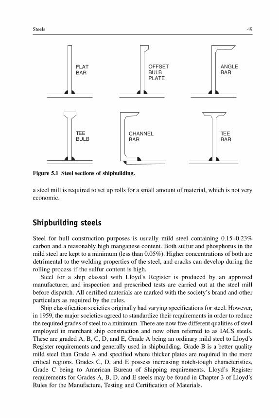
a steel mill is required to set up rolls for a small amount of material, which is not veryeconomic.
Shipbuilding steels
Steel for hull construction purposes is usually mild steel containing 0.15–0.23%carbon and a reasonably high manganese content. Both sulfur and phosphorus in themild steel are kept to a minimum (less than 0.05%). Higher concentrations of both aredetrimental to the welding properties of the steel, and cracks can develop during therolling process if the sulfur content is high.
Steel for a ship classed with Lloyd’s Register is produced by an approvedmanufacturer, and inspection and prescribed tests are carried out at the steel millbefore dispatch. All certified materials are marked with the society’s brand and otherparticulars as required by the rules.
Ship classification societies originally had varying specifications for steel. However,in 1959, the major societies agreed to standardize their requirements in order to reducethe required grades of steel to a minimum. There are now five different qualities of steelemployed in merchant ship construction and now often referred to as IACS steels.These are graded A, B, C, D, and E, Grade A being an ordinary mild steel to Lloyd’sRegister requirements and generally used in shipbuilding. Grade B is a better qualitymild steel than Grade A and specified where thicker plates are required in the morecritical regions. Grades C, D, and E possess increasing notch-tough characteristics,Grade C being to American Bureau of Shipping requirements. Lloyd’s Registerrequirements for Grades A, B, D, and E steels may be found in Chapter 3 of Lloyd’sRules for the Manufacture, Testing and Certification of Materials.
FLATBAR
CHANNELBAR
TEEBAR
TEEBULB
OFFSETBULBPLATE
ANGLEBAR
Figure 5.1 Steel sections of shipbuilding.
Steels 49

High tensile steels
Steels having a higher strength than that of mild steel are employed in the more highlystressed regions of large tankers, container ships, and bulk carriers. Use of higherstrength steels allows reductions in thickness of deck, bottom shell, and framingwhere fitted in the midships portion of larger vessels; it does, however, lead to largerdeflections. The weldability of higher tensile steels is an important consideration intheir application in ship structures and the question of reduced fatigue life with thesesteels has been suggested. Also, the effects of corrosion with lesser thicknesses ofplate and section may require more vigilant inspection.
Higher tensile steels used for hull construction purposes are manufactured andtested in accordance with Lloyd’s Register requirements. Full specifications of themethods of manufacture, chemical composition, heat treatment, and mechanicalproperties required for the higher tensile steels are given in Chapter 3 of Lloyd’sRules for the Manufacture, Testing and Certification of Materials. The higherstrength steels are available at three strength levels, 32, 36, and 40 (kg/mm2), whensupplied in the as-rolled or normalized condition. Provision is also made formaterial with six higher strength levels, 42, 46, 50, 55, 62, and 69 (kg/mm2), whensupplied in the quenched and tempered condition. Each strength level is subdividedinto four grades, AH, DH, EH, and FH, depending on the required level of notchtoughness.
Corrosion-resistant steels
Steels with alloying elements that give them good corrosion resistance andcolloquially referred to as stainless steels are not commonly used in ship struc-tures, primarily because of their higher initial and fabrication costs. Only in thefabrication of cargo tanks containing highly corrosive cargoes might such steels befound.
For oil tankers the inner surfaces, particularly the deckhead and bottom, aregenerally protected by high-cost corrosion-resistant coatings that require vigilantinspection and maintenance (see Chapter 27). A recent development in the manu-facture of an alloyed shipbuilding steel with claimed improved corrosion resistanceproperties and its approval by Lloyd’s Register for use in certain cargo tanks ofa 105,000 dwt tanker indicate that in the future the need to coat oil cargo tanks mightbe dispensed with.
Steel sandwich panels
As an alternative to conventional shipyard-fabricated stiffened steel plate structures,proprietary manufactured steel sandwich panels have become available and used onships where their lighter weight was important. Such panels consist of a steel core in
50 Ship Construction

the form of a honeycomb with flanges to which the external steel sheets are resistance(spot) or laser (stake) welded. Early use of these bought-in steel sandwich panels wasprimarily for nonhull structures in naval construction, where their light weight wasimportant. Such panels have also been used for the superstructures of passenger ships,where lightness can allow additional decks and hence increased passenger accom-modation. Also, when fabricated using stainless steel their corrosion resistance andlow maintenance properties have been utilized.
A proprietary steel sandwich plate system (SPS) has been developed that consistsof an elastomer core between steel face plates. Elastomers are a specific class ofpolyurethane that has a high tolerance to mechanical stress, i.e. it rapidly recoversfrom deformation. The SPS elastomer also has a high resistance to most commonchemical species. Initial application of SPS in shipbuilding has been in passenger shipsuperstructures, where the absence of stiffening has increased the space available andprovided factory-finished surfaces with built-in vibration damping, acoustic insu-lation, and fire protection. SPS structures have been approved with an A 60 fire-resistance rating (see Chapter 27). The main use of this system has been for repair ofships, especially decks. A single steel panel is used to secure the elastomer core to theexisting deck. This creates a sandwich panel that is structurally acceptable. The majorbenefit is in the reduced time required to complete a major steelwork repair, comparedto removing and replacing existing, corroded structure. SPS structures can be fabri-cated using joining technologies presently used in the shipbuilding industry, but thedesign of all joints must take into account the structural and material characteristics ofthe metal–elastomer composite. The manufacturer envisages the use of SPS panelsthroughout the hull and superstructure of ships, providing a simpler construction withgreater carrying capacity and less corrosion, maintenance, and inspection. In asso-ciation with the manufacturer, Lloyd’s Register in early 2006 published provisionalrules for the use of this sandwich plate system for new construction and ship repair.The rules cover construction procedures, scantling determination for primary sup-porting structures, framing arrangements, and methods of scantling determination forsteel sandwich panels.
The Norwegian classification society, Det Norske Veritas (DNV), have devel-oped proposals for ship hulls using a lightweight concrete/steel sandwich. Theyenvisaged a steel/concrete/steel composite structure for the cargo hold area ofsome 600 mm width for the side shell but somewhat greater width for the doublebottom area. This sandwich would be much narrower than for a comparable steel-only double-skin bulk carrier, thus increasing the potential carrying capacity,although water ballast may have to be carried in some designated holds as thedouble skin would not be available for this purpose. DNV consider the otheradvantages of the concrete/steel sandwich to be reduced stress concentrations withless cracking in critical areas, considerable elimination of corrosion, and elimi-nation of local buckling. The conclusions from the study, a report on which isavailable for download, are that the sandwich has potential applications for smallvessels, for short sea or rivers, and for some offshore structures. It does not appearviable for larger, ocean-going ships at present. Similar panels have been adopted insome offshore applications.
Steels 51

Steel castings
Molten steel produced by the open hearth, electric furnace, or oxygen process ispoured into a carefully constructed mold and allowed to solidify to the shape required.After removal from the mold, a heat treatment is required, for example annealing, ornormalizing and tempering to reduce brittleness. Stern frames, rudder frames, spec-tacle frames for bossings, and other structural components may be produced ascastings.
Steel forgings
Forging is simply a method of shaping a metal by heating it to a temperature where itbecomes more or less plastic and then hammering or squeezing it to the requiredform. Forgings are manufactured from killed steel made by the open hearth, electricfurnace, or oxygen process, the steel being in the form of ingots cast in chill molds.Adequate top and bottom discards are made to ensure no harmful segregations in thefinished forgings and the sound ingot is gradually and uniformly hot worked. Wherepossible the working of the metal is such that metal flow is in the most favorabledirection with regard to the mode of stressing in service. Subsequent heat treatment isrequired, preferably annealing or normalizing and tempering to remove effects ofworking and non-uniform cooling.
Further reading
Lloyd’s Register, Rules and Regulations for the Classification of Ships 2011, Rules for theManufacture, Testing and Certification of Materials.
Some useful websites
http://lloydsregister.axinteractive.com/category/2-marine.aspx Lloyd’s Register rules forclassification of ships, including downloadable information on materials.
http://eagle.org Website for ABS with downloadable rules, including materials, welding, andtesting.
www.ie-sps.com For more information about SPS systems.http://www.dnv.com/industry/maritime/ News about sandwich panels.
52 Ship Construction

6 Other shipbuilding materials
Chapter OutlineAluminum alloy 53Production of aluminum 54
Aluminum alloys 55Riveting 55
Aluminum alloy sandwich panels 57Fire protection 57Fiber-reinforced composites (FRCs) 58Some useful websites 59
Aluminum alloy
There are three advantages that aluminum alloys have over mild steel in theconstruction of ships. Firstly, aluminum is lighter than mild steel (approximateweights being 2.723 tonnes/m3, mild steel 7.84 tonnes/m3), and with an aluminumstructure it has been suggested that up to 60% of the weight of a steel structure may besaved. This is in fact the principal advantage as far as merchant ships are concerned,the other two advantages of aluminum being a high resistance to corrosion and itsnonmagnetic properties. The nonmagnetic properties can have advantages inwarships and locally in the way of the magnetic compass, but they are generally oflittle importance in merchant vessels. Good corrosion properties can be utilized, butcorrect maintenance procedures and careful insulation from the adjoining steelstructure are necessary. A major disadvantage of the use of aluminum alloys is theirhigher initial and fabrication costs. The higher costs must be offset by an increasedearning capacity of the vessel, resulting from a reduced lightship weight or increasedpassenger accommodation on the same ship dimensions. Experience with largepassenger liners on the North Atlantic service has indicated that maintenance costs ofaluminum alloy structures can be higher for this type of ship and service.
Although aluminum was first used for small craft in 1891 and for experimentalnaval vessels in 1894, it has not been a significant material for ships until compar-atively recently.
A significant number of larger ships have been fitted with superstructures ofaluminum alloy and, apart from the resulting reduction in displacement, benefits havebeen obtained in improving the transverse stability. Since the reduced weight of
Ship Construction. DOI: 10.1016/B978-0-08-097239-8.00006-4
Copyright � 2012 Elsevier Ltd. All rights reserved.

superstructure is at a position above the ship’s center of gravity, this ensures a lowercenter of gravity than that obtained with a comparable steel structure. For example, onthe Queen Elizabeth 2 with a limited beam to transit the Panama Canal, the top fivedecks constructed of aluminum alloy enabled the ship to support one more deck thanwould have been possible with an all-steel construction.
Only in those vessels having a fairly high speed and hence power, also ships wherethe deadweight/lightweight ratio is low, are appreciable savings to be expected. Suchships are moderate- and high-speed passenger liners having a low deadweight. It isinteresting to note, however, that for the Queen Mary 2, not having a beam limitation,the owners decided to avoid aluminum alloy as far as possible to ensure ease ofmaintenance over a life cycle of 40 years. A very small number of cargo liners havebeen fitted with an aluminum alloy superstructure, principally to clear a fixed draftover a river bar with maximum cargo.
Smaller naval vessels have often had aluminum superstructures on a steel hull asa weight saving measure. A difficulty is the joining of the two metals, in such a way asto avoid a corrosion cell being set up. Either bolted connections with washers toseparate the two metals, or an explosively bonded steel/aluminum transition piece(trade name ‘Kelomet’ and produced by Nobles explosives) can be used. In theexplosively bonded material the interface between the metals remains corrosion free.
The total construction in aluminum alloy of a large ship is not considered aneconomic proposition and it is only in the construction of smaller multi-hull and otherhigh-speed craft where aluminum alloys of higher strength-to-weight ratio are fullyused to good advantage. Aluminum has been used for specialized craft, includinghydrofoils, and is currently particularly used for high-speed ferries where weight iscritical. The material is also used for small, high-speed military vessels.
One advantage of aluminum is that the material can be extruded to produce a verywide range of profiles. These can have benefits in design of efficient structures. Anexample is a plate that is extruded with stiffeners as part of the profile. The plates canbe joined to assemble deck panels, with minimum welding and hence a lower risk ofdistortion. The production process is also faster. Specialized extrusions can beexpensive so the economic benefits have to be considered carefully.
Production of aluminum
For aluminum production at the present time the ore, bauxite, is mined containingroughly 56% aluminum. The actual extraction of the aluminum from the ore isa complicated and costly process involving two distinct stages. Firstly, the bauxite ispurified to obtain pure aluminum oxide, known as alumina; the alumina is thenreduced to metallic aluminum. The metal is cast in pig or ingot forms and alloys areadded where required before the metal is cast into billets or slabs for subsequentrolling, extrusion, or other forming operations.
Sectional material is mostly produced by the extrusion process. This involvesforcing a billet of the hot material through a die of the desired shape. More intricateshapes are produced by this method than are possible with steel, where the sections
54 Ship Construction
are rolled. However, the range of thickness of section may be limited since eachthickness requires a different die. Typical sections are shown in Figure 6.1.
Aluminum alloys
Pure aluminum has a low tensile strength and is of little use for structural purposes;therefore, the pure metal is alloyed with small percentages of other materials to givegreater tensile strengths (see Table 6.1). There are a number of aluminum alloys inuse, but these may be separated into two distinct groups, nonheat-treated alloys andheat-treated alloys. The latter, as implied, are subjected to a carefully controlledheating and cooling cycle in order to improve the tensile strength.
Cold working of the nonheat-treated plate has the effect of strengthening thematerial and this can be employed to advantage. However, at the same time the platebecomes less ductile, and if cold working is considerable the material may crack; thisplaces a limit on the amount of cold forming possible in ship building. Cold-workedalloys may be subsequently subjected to a slow heating and cooling annealing orstabilizing process to improve their ductility.
With aluminum alloys a suitable heat treatment is necessary to obtain a high tensilestrength. A heat-treated aluminum alloy that is suitable for shipbuilding purposes isone having as its main alloying constituents magnesium and silicon. These forma compound Mg2Si and the resulting alloy has very good resistance to corrosion anda higher ultimate tensile strength than that of the nonheat-treated alloys. Since thematerial is heat treated to achieve this increased strength, subsequent heating, forexample welding or hot forming, may destroy the improved properties locally.
Aluminum alloys are generally identified by their Aluminum Association numericdesignation, the 5000 alloys being nonheat treated and the 6000 alloys being heattreated. The nature of any treatment is indicated by additional lettering andnumbering. Lloyd’s Register prescribes the following commonly used alloys inshipbuilding:
Riveting
Riveting may be used to attach stiffening members to light aluminum alloy platedstructures where appearance is important and distortion from the heat input ofwelding is to be avoided.
5083-0 annealed5083-F as fabricated5083-H321 strain hardened and stabilized5086-0 annealed5086-F as fabricated5086-H321 strain hardened and stabilized6061-T6 solution heat treated and artificially aged6082-T6 solution heat treated and artificially aged
Other shipbuilding materials 55

Figure 6.1 Typical aluminum alloy sections.
56 Ship Construction
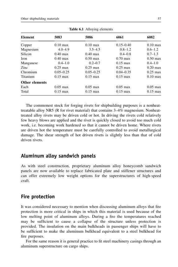
The commonest stock for forging rivets for shipbuilding purposes is a nonheat-treatable alloy NR5 (R for rivet material) that contains 3–4% magnesium. Nonheat-treated alloy rivets may be driven cold or hot. In driving the rivets cold relativelyfew heavy blows are applied and the rivet is quickly closed to avoid too much coldwork, i.e. becoming work hardened so that it cannot be driven home. Where rivetsare driven hot the temperature must be carefully controlled to avoid metallurgicaldamage. The shear strength of hot driven rivets is slightly less than that of colddriven rivets.
Aluminum alloy sandwich panels
As with steel construction, proprietary aluminum alloy honeycomb sandwichpanels are now available to replace fabricated plate and stiffener structures andcan offer extremely low weight options for the superstructures of high-speedcraft.
Fire protection
It was considered necessary to mention when discussing aluminum alloys that fireprotection is more critical in ships in which this material is used because of thelow melting point of aluminum alloys. During a fire the temperatures reachedmay be sufficient to cause a collapse of the structure unless protection isprovided. The insulation on the main bulkheads in passenger ships will have tobe sufficient to make the aluminum bulkhead equivalent to a steel bulkhead forfire purposes.
For the same reason it is general practice to fit steel machinery casings through analuminum superstructure on cargo ships.
Table 6.1 Alloying elements
Element 5083 5086 6061 6082
Copper 0.10 max 0.10 max 0.15–0.40 0.10 maxMagnesium 4.0–4.9 3.5–4.5 0.8–1.2 0.6–1.2Silicon 0.40 max 0.40 max 0.4–0.8 0.7–1.3Iron 0.40 max 0.50 max 0.70 max 0.50 maxManganese 0.4–1.0 0.2–0.7 0.15 max 0.4–1.0Zinc 0.25 max 0.25 max 0.25 max 0.20 maxChromium 0.05–0.25 0.05–0.25 0.04–0.35 0.25 maxTitanium 0.15 max 0.15 max 0.15 max 0.10 max
Other elementsEach 0.05 max 0.05 max 0.05 max 0.05 maxTotal 0.15 max 0.15 max 0.15 max 0.15 max
Other shipbuilding materials 57

Fiber-reinforced composites (FRCs)
Composite materials combine two elements with very different characteristics toprovide a material with good structural capability. The fiber provides the strength andthe matrix in which it is contained, usually a plastic, holds the fiber in place. The fibercan be arranged to provide directional strength so the composite can be tailored tovery specific structural requirements.
Composites have a lengthy history, for example mud bricks reinforced with straware a composite, as is reinforced concrete. For marine applications glass fiber-reinforced plastic (GRP), first introduced in the 1950s, is the main material for smallboats. It can be considered to be themost forgiving of all constructionmedia. There canbe problems with poor construction technique, and this can result in expensive repairs,for example due to hull and deck cores becoming water saturated and laminatesblistered. However, well-built GRP boats can still be operational after 50 years.
FRC is used extensively in leisure craft, where it provides advantages of lightnessand durability. FRC has also been used for naval vessels, in particular mine coun-termeasures vessels, where the attraction of the material is that it is nonmagnetic. Thevessels are relatively large, typically around 50 meters loa. The ‘Visby’ classcorvettes, built for the Swedish navy by Kockums AB, have an overall length of 72.7meters and a beam of 10.4 meters.
The largest composite vessel is the superyacht ‘Mirabella V’, which has an overalllength of 75.2 meters and a beam of 14.82 meters. The full load displacement is 700tonnes. For both a mine countermeasures ship and a luxury yacht the proportion of costrepresented by the hull is small. Such large vessels would probably not be economic fora commercial application, due to the labor-intensive nature of FRP construction.
Major advantages of FRP for small vessels include low weight, combined withhigh strength and stiffness. The material is resistant to harsh marine environments.The hull is laid up as a continuous structure, with no seams, which avoids any possibleleakage problems. FRP is durable and has low maintenance requirements.
For specialist applications the ability of FRP to absorb high energy can be valu-able, and the material can be tailored for specific loadings. This gives excellent designflexibility and leads to efficient structures.
The material consists of fibers, usually glass but including Kevlar and carbonfibers, for very high strength and low weight applications, which are bound intoa resin. The higher strength fibers are used in such applications as masts, wherestrength and light weight are important considerations. For most FRP applications thefibers may be randomly arranged in a chopped strand mat or woven into a specificmaterial to provide additional strength.
The hull is laid up in a mold. The mold is built using a former, known as the ‘plug’,which is an initial hull form. Once the mold is made it can be used many times, whichis one reason for the popularity of the material for small boats. The mold has to becarefully supported to ensure it does not deform under the loads imposed by the FRPand the production activities. The surface finish of the mold is important as this willdetermine the smoothness of the finished hull.
58 Ship Construction

A coating of PV (a clear odorless liquid), known as the releasing agent, is appliedto the mold to prevent the mold from sticking to the plug or finished hull. Then a gelcoat is applied, which once cured will form the smooth, water-resistant outer surfaceof the hull. At this stage the gel coat can be colored. The glass mat or woven roving isthen laid onto the mold and the resin applied. The mat can be cut to match the hullshape. It is important that the fibers are thoroughly wetted by the resin and that all airis excluded. The hull is built up to the required thickness with several layers of glass.Additional glass is used to build up thicker material where additional strength isrequired.
Stiffeners can be incorporated in the hull. These are usually a solid or hollow coreformer. These are positioned on the hull in the mold and then covered with the glassand resin. When covered with several layers of fiberglass mat they create a closed boxor semicircular section. These are known as ‘top-hat’ and ‘half-round’ stiffeners.Internal fittings, machinery mountings, and locations for bulkheads are also built intothe hull as it progresses. Once the hull, and fittings incorporated into it, are completethe hull is left to cure until the resin is fully set.
The mold is often in two halves for small vessels and this allows it to be split torelease the hull.
Some useful websites
www.austal.com Construction of aluminum fast vessels.http://www.sciencedirect.com/science/article/pii/S0950061889800029 Makes available an
article on Kelomet explosively bonded steel/aluminum joining pieces.http://www.nationalcompositescentre.co.uk/ General information on composite use and
developments.http://www.reinforcedplastics.com/ Also general information on composites and specific
reports on boats.
Other shipbuilding materials 59

7 Testing of materials
Chapter OutlineClassification society tests for hull materials 63
Tensile test 63Impact tests 63Aluminum alloy tests 65
Metals are tested to ensure that their strength, ductility, and toughness are suitable forthe function they are required to perform.
Material properties are important to the capability of the structure. The propertiesoutlined below are appropriate in determining the suitability of a material for shipconstruction.
The strength of the material is its ability to resist deformation. Yield stress andultimate tensile strength measure the ability to resist forces on the structure.
Hardness of a material describes its ability to resist abrasion. Hardness is impor-tant, for example, in bulk carriers where the cargo handling produces abrasive actionon the cargo hold structures. Hardness is usually measured on a scale (Rockwell orBrinell), based on test results.
Ductility is the ability of a material to be deformed before it fails.Brittleness is the opposite of ductility and describes a material that fails under
stress because it cannot deform. Softer metals, such as aluminum, are ductile. Hardmaterials such as cast iron are strong but brittle.
Toughness is the ability of a material to absorb energy.In comparing the strengths of various metals, stresses and strains are often referred
to and require to be defined. Stress is a measure of the ability of a material to transmita load, and the intensity of stress in the material, which is the load per unit area, isoften stated. The load per unit area is simply obtained by dividing the applied load bythe cross-sectional area of the material, e.g. if a tensile load of P kg is applied to a rodhaving a cross-sectional area of A mm2, then the tensile stress in the material of therod is P/A kg/mm2 (see Figure 7.1).
Total strain is defined as the total deformation that a body undergoes whensubjected to an applied load. The strain is the deformation per unit length orunit volume, e.g. if the tensile load P applied to the rod of original length lproduces an elongation, or extension, of the rod of amount dl, then the tensile
Ship Construction. DOI: 10.1016/B978-0-08-097239-8.00007-6
Copyright � 2012 Elsevier Ltd. All rights reserved.
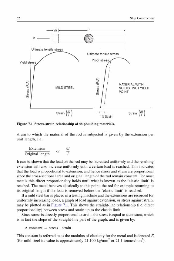
strain to which the material of the rod is subjected is given by the extension perunit length, i.e.
Extension
Original lengthor
dl
l
It can be shown that the load on the rod may be increased uniformly and the resultingextension will also increase uniformly until a certain load is reached. This indicatesthat the load is proportional to extension, and hence stress and strain are proportionalsince the cross-sectional area and original length of the rod remain constant. For mostmetals this direct proportionality holds until what is known as the ‘elastic limit’ isreached. The metal behaves elastically to this point, the rod for example returning toits original length if the load is removed before the ‘elastic limit’ is reached.
If a mild steel bar is placed in a testing machine and the extensions are recorded foruniformly increasing loads, a graph of load against extension, or stress against strain,may be plotted as in Figure 7.1. This shows the straight-line relationship (i.e. directproportionality) between stress and strain up to the elastic limit.
Since stress is directly proportional to strain, the stress is equal to a constant, whichis in fact the slope of the straight-line part of the graph, and is given by:
A constant ¼ stressOstrain
This constant is referred to as the modulus of elasticity for the metal and is denoted E(for mild steel its value is approximately 21,100 kg/mm2 or 21.1 tonnes/mm2).
MILD STEEL
Ultimate tensile stress
Yield stress
Str
ess
(P/A
)l
Ultimate tensile stress
Proof stress
Str
ess
(P/A
)
StrainStrain1% Strain
P
llll
MATERIAL WITHNO DISTINCT YIELDPOINT
A
l
Figure 7.1 Stress–strain relationship of shipbuilding materials.
62 Ship Construction

The yield stress for a metal corresponds to the stress at the ‘yield point’; that is, thepoint at which the metal no longer behaves elastically. Ultimate tensile stress is themaximum load to which the metal is subjected, divided by the original cross-sectionalarea. Beyond the yield point the metal behaves plastically, which means that the metaldeforms at a greater, unproportional, rate when the yield stress is exceeded, and willnot return to its original dimensions on removal of the load. It becomes deformed or isoften said to be permanently ‘set’.
Many metals do not have a clearly defined yield point, for example aluminum,having a stress–strain curve over its lower range that is a straight line becominggradually curved without any sharp transformation on yielding, as shown by mildsteel (see Figure 7.1). A ‘proof stress’ is quoted for the material and this may beobtained by setting off on the base some percentage of the strain, say 0.2%, anddrawing a line parallel to the straight portion of the curve. The intersection of this linewith the actual stress–strain curve marks the proof stress.
It is worth noting at this stage that the ship’s structure is designed for workingstresses that are within the elastic range and much lower than the ultimate tensilestrength of the material to allow a reasonable factor of safety.
Classification society tests for hull materials
Both mild steel and higher tensile steel plates and sections built into a ship are to beproduced at works approved by the appropriate classification society. Duringproduction an analysis of the material is required and so are prescribed tests of therolled metal. Similar analyses and tests are required by the classification societies forsteel forgings and steel castings, in order to maintain an approved quality.
Destructive tests are made on specimens obtained from the same product asthe finishedmaterial in accordancewith the societies’ requirements, whichmay be foundin the appropriate rules. These tests usually take the form of a tensile test and impact test.
Tensile test
The basic principle of this test has already been described, a specimen of givendimensions being subject to an axial pull and a minimum specified yield stress,ultimate tensile stress, and elongation must be obtained. In order to make compari-sons between the elongation of tensile test pieces of the same material the test piecesmust have the same proportions of sectional area and gage length. Therefore,a standard gage length equal to 5.65 times the square root of the cross-sectional area,which is equivalent to a gage length of five times the diameter, is adopted by the majorclassification societies.
Impact tests
There are several forms of impact test, but the Charpy V-notch test or Charpy U-notchtest is commonly specified and therefore described in this text. The object of the
Testing of materials 63

45°
CHARPY IMPACT TEST
Pointer
Scale
End ofswing
Hammer
Specimen
Start ofswing
Anvil
CHARPY VEENOTCH SPECIMEN
Hammerblow
10 mmx
10 mm
55 mm
8 mm
40 mm
0.25 mmradius
Figure 7.2 Charpy impact test.
64
Ship
Constru
ction

impact test is to determine the toughness of the material; that is, its ability to with-stand fracture under shock loading. In Figure 7.2 the principle of the Charpy testmachine is illustrated, along with the standard test specimen for a Charpy V-notchtest. This specimen is placed on an anvil and the pendulum is allowed to swing so thatthe striker hits the specimen opposite the notch and fractures it. Energy absorbed infracturing the specimen is automatically recorded by the machine. Basically, makingallowances for friction, the energy absorbed in fracturing the specimen is thedifference between the potential energy the pendulum possesses before beingreleased, and that which it attains in swinging past the vertical after fracturing thespecimen. A specified average impact energy for the specimens tested must beobtained at the specified test temperature, fracture energy being dependent ontemperature, as will be illustrated in Chapter 8.
Aluminum alloy tests
Aluminum alloy plate and section material is subject to specified tensile tests. Barmaterial for aluminum alloy rivets is subject to a tensile test and also a dump test. Thelatter test requires compression of the bar until its diameter is increased to 1.6 timesthe original diameter without cracking occurring. Selected manufactured rivets arealso subjected to the same dump test.
Testing of materials 65

8 Stresses to which a ship is subject
Chapter OutlineVertical shear and longitudinal bending in still water 67Bending moments in a seaway 68Longitudinal shear forces 68Bending stresses 68
The ship as a beam 71Strength deck 71
Transverse stresses 73Racking 73Torsion 73
Local stresses 73Panting 73Pounding 74Other local stresses 74
Brittle fracture 75Fatigue failures 76Buckling 76Monitoring ship stresses at sea 78Further reading 78Some useful websites 78
The stresses experienced by the ship floating in still water and when at sea mayconveniently be considered separately.
Vertical shear and longitudinal bending in still water
If a homogeneous body of uniform cross-section and weight is floating in still water,at any section the weight and buoyancy forces are equal and opposite. Therefore, thereis no resultant force at a section and the body will not be stressed or deformed. A shipfloating in still water has an unevenly distributed weight owing to both cargodistribution and structural distribution. The buoyancy distribution is also non-uniformsince the underwater sectional area is not constant along the length. Total weight andtotal buoyancy are of course balanced, but at each section there will be a resultantforce or load, either an excess of buoyancy or excess of load. Since the vessel remainsintact there are vertical upward and downward forces tending to distort the vessel
Ship Construction. DOI: 10.1016/B978-0-08-097239-8.00008-8
Copyright � 2012 Elsevier Ltd. All rights reserved.
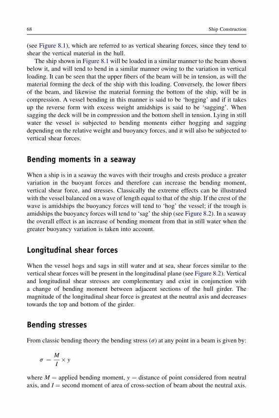
(see Figure 8.1), which are referred to as vertical shearing forces, since they tend toshear the vertical material in the hull.
The ship shown in Figure 8.1 will be loaded in a similar manner to the beam shownbelow it, and will tend to bend in a similar manner owing to the variation in verticalloading. It can be seen that the upper fibers of the beam will be in tension, as will thematerial forming the deck of the ship with this loading. Conversely, the lower fibersof the beam, and likewise the material forming the bottom of the ship, will be incompression. A vessel bending in this manner is said to be ‘hogging’ and if it takesup the reverse form with excess weight amidships is said to be ‘sagging’. Whensagging the deck will be in compression and the bottom shell in tension. Lying in stillwater the vessel is subjected to bending moments either hogging and saggingdepending on the relative weight and buoyancy forces, and it will also be subjected tovertical shear forces.
Bending moments in a seaway
When a ship is in a seaway the waves with their troughs and crests produce a greatervariation in the buoyant forces and therefore can increase the bending moment,vertical shear force, and stresses. Classically the extreme effects can be illustratedwith the vessel balanced on a wave of length equal to that of the ship. If the crest of thewave is amidships the buoyancy forces will tend to ‘hog’ the vessel; if the trough isamidships the buoyancy forces will tend to ‘sag’ the ship (see Figure 8.2). In a seawaythe overall effect is an increase of bending moment from that in still water when thegreater buoyancy variation is taken into account.
Longitudinal shear forces
When the vessel hogs and sags in still water and at sea, shear forces similar to thevertical shear forces will be present in the longitudinal plane (see Figure 8.2). Verticaland longitudinal shear stresses are complementary and exist in conjunction witha change of bending moment between adjacent sections of the hull girder. Themagnitude of the longitudinal shear force is greatest at the neutral axis and decreasestowards the top and bottom of the girder.
Bending stresses
From classic bending theory the bending stress (s) at any point in a beam is given by:
s ¼ M
I� y
where M ¼ applied bending moment, y ¼ distance of point considered from neutralaxis, and I ¼ second moment of area of cross-section of beam about the neutral axis.
68 Ship Construction

12001400
14002000
2100
1700 19001800 1100
200
1700 900 200
300 Tonnes 200 Tonnes
100 Tonnes 200 Tonnes
200 Tonnes
200 Tonnes
100 Tonnes 200 Tonnes
300 Tonnes
200 Tonnes
400
400 1000
Figure 8.1 Vertical shear and longitudinal bending in still water.
Stresses
towhich
aship
issubject
69

CrestCrest Crest
Crest
Trough
TroughTrough Trough
SAGGING
HOGGING
Longitudinal shear forces
Figure 8.2 Wave bending moments.
70
Ship
Constru
ction

When the beam bends it is seen that the extreme fibers are, say in the case of hogging,in tension at the top and in compression at the bottom. Somewhere between the twothere is a position where the fibers are neither in tension nor compression. Thisposition is called the neutral axis, and at the furthest fibers from the neutral axis thegreatest stress occurs for plane bending. It should be noted that the neutral axis alwayscontains the center of gravity of the cross-section. In the equation the second momentof area (I) of the section is a divisor; therefore, the greater the value of the secondmoment of area, the less the bending stress will be. This second moment of area ofsection varies as the depth squared and therefore a small increase in depth of sectioncan be very beneficial in reducing the bending stress. Occasionally reference ismade to the sectional modulus (Z) of a beam; this is simply the ratio between thesecond moment of area and the distance of the point considered from the neutral axis,i.e. I/y ¼ Z.
The bending stress (s) is then given by s ¼ M/Z.
The ship as a beam
It was seen earlier that the ship bends like a beam, and in fact the hull can beconsidered as a box-shaped girder for which the position of the neutral axis andsecond moment of area may be calculated. The deck and bottom shell form theflanges of the hull girder, and are far more important to longitudinal strength than thesides that form the web of the girder and carry the shear forces. The box-shaped hullgirder and a conventional I girder are compared in Figure 8.3.
In a ship the neutral axis is generally nearer the bottom, since the bottom shell willbe heavier than the deck, having to resist water pressure as well as the bendingstresses. In calculating the second moment of an area of the cross-section all longi-tudinal material is of greatest importance and the further the material is from theneutral axis, the greater will be its second moment of area about the neutral axis.However, at greater distances from the neutral axis, the sectional modulus will bereduced and correspondingly higher stress may occur in extreme hull girder platessuch as the deck stringer, sheer strake, and bilge. These strakes of plating aregenerally heavier than other plating.
Bending stresses are greater over the middle portion of the length and it is owing tothis variation that Lloyd’s give maximum scantlings over 40% of the length amid-ships. Other scantlings may taper towards the ends of the ship, apart from locallyhighly stressed regions where other forms of loading are encountered.
Strength deck
The deck forming the uppermost flange of the main hull girder is often referred to asthe strength deck. This is to some extent a misleading term since all continuous decksare in fact strength decks if properly constructed. Along the length of the ship the topflange of the hull girder, i.e. the strength deck, may step from deck to deck where largesuperstructures are fitted or there is a natural break, for instance in way of a raisedquarter deck. Larger superstructures tend to deform with the main hull and stresses of
Stresses to which a ship is subject 71

Flange
Web Web Web
I SECTION GIRDER BOX GIRDER SHIP HULL GIRDER
FlangeFlange
FlangeFlange
Flange
Figure 8.3 Box girder and I girder.
72
Ship
Constru
ction

appreciable magnitude will occur in the structure. Early vessels fitted with largesuperstructures of light construction demonstrated this to their cost. Attempts to avoidfracture have been made by fitting expansion joints, which made the light structurediscontinuous. These were not entirely successful and the expansion joint may itselfform a stress concentration at the strength deck, which one would wish to avoid. Inmodern construction the superstructure is usually made continuous and of suchstrength that its sectional modulus is equivalent to that which the strength deck wouldhave if no superstructure were fitted (see Chapter 19).
Transverse stresses
When a ship experiences transverse forces these tend to change the shape of thevessel’s cross-sections and thereby introduce transverse stresses. These forces may beproduced by hydrostatic loads and impact of seas or cargo and structural weights, bothdirectly and as the result of reactions due to change of ship motion.
Racking
When a ship is rolling, the deck tends to move laterally relative to the bottom structure,and the shell on one side to move vertically relative to the other side. This type ofdeformation is referred to as ‘racking’. Transverse bulkheads primarily resist suchtransverse deformation, the side frames’ contribution being insignificant provided thetransverse bulkheads are at their usual regular spacings. Where transverse bulkheadsare widely spaced, deep web frames and beams may be introduced to compensate.
Torsion
When any body is subject to a twisting moment, which is commonly referred to astorque, that body is said to be in ‘torsion’. A ship heading obliquely (45�) to a wavewill be subjected to righting moments of opposite direction at its ends, twisting thehull and putting it in ‘torsion’. In most ships these torsional moments and stresses arenegligible but in ships with extremely wide and long deck openings they aresignificant. A particular example is the larger container ship, where at the topsidesa heavy torsion box girder structure including the upper deck is provided toaccommodate the torsional stresses (see Figures 8.4 and 17.9).
Local stresses
Panting
Panting refers to a tendency for the shell plating to work ‘in’ and ‘out’ in a bellows-like fashion, and is caused by the fluctuating pressures on the hull at the ends when theship is amongst waves. These forces are most severe when the vessel is running into
Stresses to which a ship is subject 73

waves and is pitching heavily, the large pressures occurring over a short time cycle.Strengthening to resist panting both forward and aft is covered in Chapter 17.
Pounding
Severe local stresses occur in way of the bottom shell and framing forward whena vessel is driven into head seas. These pounding stresses, as they are known, arelikely to be most severe in a lightly ballasted condition, and occur over an area of thebottom shell aft of the collision bulkhead. Additional stiffening is required in thisregion; this is dealt with in Chapter 16.
Other local stresses
Ship structural members are often subjected to high stresses in localized areas, andgreat care is required to ensure that these areas are correctly designed. This isparticularly the case where various load-carrying members of the ship intersect,examples being where longitudinals meet at transverse bulkheads and at intersections
Crest
Crest
Container shipsection
Torsionbox
Figure 8.4 Torsion.
74 Ship Construction
of longitudinal and transverse bulkheads. Another highly stressed area occurs wherethere is a discontinuity of the hull girder at ends of deck house structures, also at hatchand other opening corners, and where there are sudden breaks in the bulwarks.
Brittle fracture
With the large-scale introduction of welding in ship construction, much considerationhas been given to the correct selection of materials and structural design to prevent thepossibility of brittle fracture occurring. During the Second World War the incidenceof this phenomenon was high amongst tonnage hastily constructed, whilst little wasknown about the mechanics of brittle fracture. Although instances of brittle fracturewere recorded in riveted ships, the consequences were more disastrous in the weldedvessels because of the continuity of metal provided by the welded joint as opposed tothe riveted lap, which tended to limit the propagating crack.
Brittle fracture occurs when an otherwise elastic material fractures without anyapparent sign or little evidence of material deformation prior to failure. Fractureoccurs instantaneously with little warning and the vessel’s overall structure need notbe subject to a high stress at the time. Mild steel used extensively in ship constructionis particularly prone to brittle fracture given the conditions necessary to trigger it off.The subject is too complex to be dealt with in detail in this text, but it is known that thefollowing factors influence the possibility of brittle fracture and are taken intoconsideration in the design and material selection of modern ships:
1. A sharp notch is present in the structure from which the fracture initiates.2. A tensile stress is present.3. There is a temperature above which brittle fracture will not occur.4. The metallurgical properties of the steel plate.5. Thick plate is more prone.
A brittle fracture is distinguishable from a ductile failure by the lack of deformation atthe edge of the tear, and its bright granular appearance. A ductile failure has a dullgray appearance. The brittle fracture is also distinguished by the apparent chevronmarking, which aids location of the fracture initiation point since these tend to pointin that direction.
Factors that are known to exist where a brittle fracture may occur must beconsidered if this is to be avoided. Firstly, the design of individual items of shipstructure must be such that sharp notches where cracks may be initiated are avoided.With welded structures as large as a ship the complete elimination of crack initiationis not entirely possible owing to the existence of small faults in the welds, a completeweld examination not being practicable. Steel specified for the hull constructionshould therefore have good ‘notch ductility’ at the service temperatures, particularlywhere thick plate is used. Provision of steel having good ‘notch ductility’ propertieshas the effect of making it difficult for a crack to propagate. Notch ductility isa measure of the relative toughness of the steel, which has already been seen to bedetermined by an impact test. Steels specified for ship construction have elements
Stresses to which a ship is subject 75

added (particularly manganese with a carbon limit), and may also be subjected toa controlled heat treatment, which will enhance the notch toughness properties.Figure 8.5 illustrates the improved notch ductility of a manganese/carbon steelagainst a plain carbon steel. Grade D and Grade E steels, which have higher notchductility, are employed where thick plate is used and in way of higher stressedregions, as will be seen when the ship structural details are considered later.
In association with the problem of brittle fracture it was not uncommon at one timeto hear reference to the term ‘crack arrester’. The term related to the now outdatedpractice of introducing riveted seams in cargo ships to subdivide the vessel intowelded substructures so that any possible crack propagation was limited to thesubstructure. In particular, such a ‘crack arrester’ was usually specified in thesheerstrake/stringer plate area of larger ships. Today strakes of higher notch tough-ness steel are required to be fitted in such areas. Lloyd’s Register, for example, requirethe mild steel sheerstrake and stringer plate at the strength deck over the midshipportion of vessels of more than 250 meters length to be Grade D if less than 15 mmthick and Grade E if of greater thickness (see Chapter 17).
Fatigue failures
Unlike brittle fracture, fatigue fracture occurs very slowly and can in fact take years topropagate. The greatest danger with fatigue fractures is that they occur at low stressesthat are applied to a structure repeatedly over a period of time (Figure 8.5). A fatiguecrack, once initiated, may grow unnoticed until the load-bearing member is reducedto a cross-sectional area that is insufficient to carry the applied load. Fatigue failuresare associated with sharp notches or discontinuities in structures, and are especiallyprevalent at ‘hard spots’, i.e. regions of high rigidity in ship structures.
With the growth in size of oil tankers, bulk carriers, and container ships there hasbeen increasing use of higher yield strength steels in their hull structures. The clas-sification societies have subsequently placed special emphasis on analysis of thefatigue performance of these larger structures, usually over a 25-year life cycle, aspart of their approval process.
Buckling
With the substantial increase in size of oil tankers, bulk carriers, and container ships inrecent years, greater attention has had to be given to the buckling strength of thestiffened plate panels constituting the shell.
Buckling of a structural member loaded in compression may occur at a stresslevel that is substantially lower than the material’s yield stress (see Figure 7.1). Theload at which buckling occurs is a function of the structural member’s geometry andthe material’s modulus of elasticity rather than the material’s strength. The mostcommon example of buckling failure is the collapse of a pillar under a compressiveload. A stiffened plate panel in compression will also have a critical buckling load
76 Ship Construction

DUCTILE/BRITTLE TRANSITIONBEHAVIOR OF STEELS
Fine grain carbonmanganese steel
Medium carbon (2%)structural steel
Temperature ( C)o
–100 –50 0 50 100 150
2.75
5.5
8.25
11.0
13.25
Cha
rpy
V n
otch
impa
ct e
nerg
y (k
g M
)16.5
FATIGUE BEHAVIOR OF PLAIN MILD STEEL
Number of cycles x 1050 1 2 3 4 5 6 7 8 9 10
Ulti
mat
e te
nsile
str
engt
h
21 kg/mm2
42 kg/mm2
Figure 8.5 Benefit of manganese/carbon steel.
Stresses to which a ship is subject 77
whose value depends on the plate thickness, unsupported dimensions, edge supportconditions, and the material’s modulus of elasticity. Unlike the pillar, however,slightly exceeding this load will not necessarily result in collapse of the plate butonly in elastic deflection of the center portion of the plate from its initial plane. Afterremoval of the load, the plate will return to its original undeformed state. Theultimate load that may be carried by a buckled plate is determined by the onset ofyielding (i.e. when the yield point of the material is reached) at some point in theplate or in the stiffeners. Once begun, this yielding may propagate rapidlythroughout the stiffened panel with further increase in load until failure of the plateor stiffeners occurs.
In recent years Lloyd’s Register has introduced for oil tankers over 150 meters inlength rules that contain formulae to check the buckling capacity of plate panels andtheir main supporting stiffeners. Where further buckling assessment is requireda computer-based general and local stiffened plate panel ultimate buckling strengthevaluation assessment procedure is used.
Monitoring ship stresses at sea
In order to enhance safety during shipboard operations, real-time motion and stressmonitoring information equipment can be supplied by classification societies such asLloyd’s Register to a ship at the owner’s request. This entails the fitting of strain gagesto the deck structure, an accelerometer, and a personal computer with software thatdisplays ship stress and motion readings on the bridge. An alarm is activated if thesafety limits are exceeded, enabling remedial action to be taken. Where this equip-ment is installed the notation SEA is assigned and if coupled to a data recorder theassigned notation is SEA(R).
Further reading
Fatigue in ship structures—New light on an eternal issue, The Naval Architect, January 2003.Rawson, Tupper: Basic Ship Theory, ed 5, vol 1, Chapter 6: The ship girder; Chapter 7:
Structural design and analysis, 2001, Butterworth Heinemann.Refined ABS rules for very large container ships, The Naval Architect, October 2005.Stress monitoring system for NASSCO’s Alaska-class tankers, The Naval Architect,
September 2003.
Some useful websites
www.iacs.org.uk See Guidelines and Recommendations—Recommendation 46 ‘BulkCarriers—Guidance and Information on Bulk Cargo Loading and Discharging to Reducethe Likelihood of Over-stressing the Hull Structure’ and Recommendation 56 ‘FatigueAssessment of Ship Structures’.
78 Ship Construction

9 Welding and cutting processes usedin shipbuilding
Chapter OutlineGas welding 82Electric arc welding 84
Slag-shielded processes 84Manual welding electrodes 86Automatic welding with cored wires 86Submerged arc welding 86Stud welding 88
Gas-shielded arc welding processes 89Tungsten inert gas (TIG) welding 89Metal inert gas (MIG) welding 89Plasma welding 93
Other welding processes 94Electro-slag welding 94Electro-gas welding 94Laser welding 95Thermit welding 96Friction stir welding1 96
Cutting processes 98Gas cutting 98Plasma-arc cutting 98Gouging 100Laser cutting 100Water jet cutting 101
Further reading 101Some useful websites 101
Initially welding was used in ships as a means of repairing various metal parts. Duringthe First World War various authorities connected with shipbuilding, includingLloyd’s Register, undertook research into welding and in some cases prototypewelded structures were built. However, riveting remained the predominant methodemployed for joining ship plates and sections until the time of the Second World War.During and after this war the use and development of welding for shipbuildingpurposes was widespread, and welding totally replaced riveting in the latter part of thetwentieth century.
Ship Construction. DOI: 10.1016/B978-0-08-097239-8.00009-X
Copyright � 2012 Elsevier Ltd. All rights reserved.
There are many advantages to be gained from employing welding in ships asopposed to having a riveted construction. These may be considered as advantages inboth building and in operating the ship.
For the shipbuilder the advantages are:
1. Welding lends itself to the adoption of prefabrication techniques.2. It is easier to obtain watertightness and oiltightness with welded joints.3. Joints are produced more quickly.4. Less skilled labor is required.
For the shipowner the advantages are:
1. Reduced hull steel weight, therefore more deadweight.2. Less maintenance from slack rivets, etc.3. The smoother hull with the elimination of overlapping plate joints leads to reduced skin
friction resistance, which can reduce fuel costs.
Other than some blacksmith work involving solid-phase welding, the weldingprocesses employed in shipbuilding are of the fusion welding type. Fusion welding isachieved by means of a heat source that is intense enough to melt the edges of thematerial to be joined as it is traversed along the joint. Gas welding, arc welding, laserwelding, and resistance welding all provide heat sources of sufficient intensity toachieve fusion welds.
Gas welding
A gas flame was probably the first form of heat source to be used for fusion welding,and a variety of fuel gases with oxygen have been used to produce a high-temperatureflame. The most commonly used gas in use is acetylene, which gives an intenseconcentrated flame (average temperature 3000 �C) when burnt in oxygen.
An oxyacetylene flame has two distinct regions: an inner cone, in which theoxygen for combustion is supplied via the torch; and a surrounding envelope, in whichsome or all the oxygen for combustion is drawn from the surrounding air. By varyingthe ratio of oxygen to acetylene in the gas mixture supplied by the torch, it is possibleto vary the efficiency of the combustion and alter the nature of the flame (Figure 9.1).If the oxygen supply is slightly greater than the supply of acetylene by volume, whatis known as an ‘oxidizing’ flame is obtained. This type of flame may be used forwelding materials of high thermal conductivity, e.g. copper, but not steels, as the steelmay be decarburized and the weld pool depleted of silicon. With equal amounts ofacetylene and oxygen a ‘neutral’ flame is obtained, and this would normally be usedfor welding steels and most other metals. Where the acetylene supply exceeds theoxygen by volume a ‘carburizing’ flame is obtained, the excess acetylene decom-posing and producing submicroscopic particles of carbon. These readily go intosolution in the molten steel, and can produce metallurgical problems in service.
The outer envelope of the oxyacetylene flame by consuming the surroundingoxygen to some extent protects the molten weld metal pool from the surrounding air.If unprotected the oxygen may diffuse into the molten metal and produce porosity
82 Ship Construction

CARBURIZING FLAME
NEUTRAL FLAME
OXIDIZING FLAME
Weld direction
Filler material Torch
Weld metal
Weld direction
Filler material Torch
Weld metal
BACKWARD (OR LEFTWARD) WELDING
FORWARD (OR RIGHTWARD) WELDING
Figure 9.1 Gas welding.
Weld
ingandcuttin
gprocesses
used
inshipbuild
ing
83

when the weld metal cools. With metals containing refractory oxides, such asstainless steels and aluminum, it is necessary to use an active flux to remove theoxides during the welding process.
Both oxygen and acetylene are supplied in cylinders, the oxygen under pressureand the acetylene dissolved in acetone since it cannot be compressed. Each cylinder,which is distinctly colored (red—acetylene, black—oxygen), has a regulator forcontrolling the working gas pressures. The welding torch consists of a long thickcopper nozzle, a gas mixer body, and valves for adjusting the oxygen and acetyleneflow rates. Usually a welding rod is used to provide filler metal for the joint, but insome cases the parts to be joined may be fused together without any filler metal. Gaswelding techniques are shown in Figure 9.1.
Oxyacetylene welding tends to be slower than other fusion welding processesbecause the process temperature is low in comparison with the melting temperature ofthe metal, and because the heat must be transferred from the flame to the plate. Theprocess is therefore only really applicable to thinner mild steel plate, thicknesses up to7 mm being welded using this process with a speed of 3–4 meters per hour. Inshipbuilding oxyacetylene welding has almost disappeared but can be employed inthe fabrication of ventilation and air-conditioning trunking, cable trays, and light steelfurniture; some plumbing and similar work may also make use of gas welding. Thesetrades may also employ the gas flame for brazing purposes, where joints are obtainedwithout reaching the fusion temperature of the material being joined.
Electric arc welding
The basic principle of electric arc welding is that a wire or electrode is connected toa source of electrical supply with a return lead to the plates to be welded. If theelectrode is brought into contact with the plates an electric current flows in the circuit.By removing the electrode a short distance from the plate, so that the electric currentis able to jump the gap, a high-temperature electrical arc is created. This will melt theplate edges and the end of the electrode if this is of the consumable type.
Electrical power sources vary, DC generators or rectifiers with variable or constantvoltage characteristics being available, as well as AC transformers with variablevoltage characteristics for single or multiple operation. The latter are most commonlyused in shipbuilding.
Illustrated in Figure 9.2 are the range of manual, semi-automatic, and automaticelectric arc welding processes that might be employed in shipbuilding. Each of theseelectric arc welding processes is discussed below with its application.
Slag-shielded processes
Metal arc welding started as bare wire welding, the wire being attached to normalpower lines. This gave unsatisfactory welds, and subsequently it was discovered thatby dipping the wire in lime a more stable arc was obtained. As a result of furtherdevelopments many forms of flux are now available for coating the wire or for
84 Ship Construction

ELECTRIC ARC WELDING PROCESSES
Inert gasshielded
Consumableelectrode
Nonconsumableelectrode
Plasmaarc
Carbonarc
Atomichydrogen
TIGargon
shielded
MIGargon
shielded
MIGCO
shielded2
Diptransfer
Pulsetransfer
Spraytransfer
Flux cored processes
Slagshielded
Shieldedmetal arc
Submergedarc
Studwelding
Figure 9.2 Electric arc welding processes.
Weld
ingandcuttin
gprocesses
used
inshipbuild
ing
85

deposition on the joint prior to welding. Other developments include a hollow wire forcontinuous welding with the flux within the hollow core. The flux melts, thensolidifies during the welding process, forming a solid slag that protects the weld fromatmospheric oxygen and nitrogen.
Manual welding electrodes
The core wire normally used for mild steel electrodes is rimming steel. This is ideal forwire-drawing purposes, and elements used to ‘kill’steel such as silicon or aluminum tendto destabilize the arc, making ‘killed’ steels unsuitable. Coatings for the electrodesnormally consist of a mixture of mineral silicates, oxides, fluorides, carbonates, hydro-carbons, and powderedmetal alloys plus a liquid binder. Aftermixing, the coating is thenextruded onto the core wire and the finished electrodes are dried in batches in ovens.
Electrode coatings should provide gas shielding for the arc, easy striking and arcstability, a protective slag, good weld shape, and most important of all a gas shieldconsuming the surrounding oxygen and protecting the molten weld metal. Variouselectrode types are available, the type often being defined by the nature of the coating.The more important types are the rutile and basic (or low-hydrogen) electrodes. Rutileelectrodes have coatings containing a high percentage of titania, and are general-purpose electrodes that are easily controlled and give a good weld finish with soundproperties. Basic or low-hydrogen electrodes, the coating of which has a high limecontent, are manufactured with the moisture content of the coating reduced toa minimum to ensure low-hydrogen properties. The mechanical properties of weldmetal deposited with this type of electrode are superior to those of other types, andbasic electrodes are generally specified for welding the higher tensile strength steels.Where high restraint occurs, for example at the final erection seam weld between twoathwartships rings of unit structure, low-hydrogen electrodes may also be employed.An experienced welder is required where this type of electrode is used since it is lesseasily controlled. Welding with manual electrodes may be accomplished in thedownhand position, for example welding at the deck from above, also in the hori-zontal vertical, or vertical positions, for example across or up a bulkhead, and in theoverhead position, for example welding at the deck from below (Figure 9.3). Weldingin any of these positions requires selection of the correct electrode (positional suit-ability stipulated by the manufacturer), correct current, correct technique, and inev-itably experience, particularly for the vertical and overhead positions.
Automatic welding with cored wires
Flux-cored wires (FCAW) are often used in mechanized welding, allowing higherdeposition rates and improved quality of weld. Basic or rutile flux-cored wires arecommonly used for one-sided welding with a ceramic backing.
Submerged arc welding
This is an arc welding process in which the arc is maintained within a blanket ofgranulated flux (see Figure 9.4). A consumable filler wire is employed and the arc is
86 Ship Construction

Voltage control
Generator
Currentcontrol
Electrode
Arc
Workpiece
A
Electrode
Weld
Electrode
WeldElectrode
Electrode
Weld
Weld
DOWNHAND
OVERHEADVERTICALHORIZONTALVERTICAL
Figure 9.3 Manual arc welding.
Weld
ingandcuttin
gprocesses
used
inshipbuild
ing
87

maintained between this wire and the parent plate. Around the arc the granulated fluxbreaks down and provides some gases, and a highly protective thermally insulatingmolten container for the arc. This allows a high concentration of heat, making theprocess very efficient and suitable for heavy deposits at fast speeds. After welding themolten metal is protected by a layer of fused flux, which together with the unfusedflux may be recovered before cooling.
This is the most commonly used process for downhand mechanical welding in theshipbuilding industry, in particular for joining plates for ship shell, decks, andbulkheads. Metal powder additions that result in a 30–50% increase in metal depo-sition rate without incurring an increase in arc energy input may be used for thewelding of joint thicknesses of 25 mm or more. Submerged arc multi-wire and twin-arc systems are also used to give high productivity.
With shipyards worldwide adopting one-side welding in their ship panel lines forimproved productivity, the submerged arc process is commonly used with a fusiblebacking, using either flux or glass fiber materials to contain and control the weldpenetration bead.
Stud welding
Stud welding may be classed as a shielded arc process, the arc being drawn betweenthe stud (electrode) and the plate to which the stud is to be attached. Each stud isinserted into a stud welding gun chuck, and a ceramic ferrule is slipped over it beforethe stud is placed against the plate surface. On depressing the gun trigger the stud isautomatically retracted from the plate and the arc established, melting the end of the
Flux
Flux
Wire feed
Electrode wire
Fused fluxRun-on plate
Completed weld
SUBMERGED ARC WELDING
Flux retained byfireproof canvas
Air hose
Ceramic backing
ONE-SIDED WELDING TECHNIQUES
Figure 9.4 Automatic arc welding.
88 Ship Construction

stud and the local plate surface. When the arcing period is complete, the current isautomatically shut off and the stud driven into a molten pool of weld metal, soattaching stud to plate.
Apart from the stud welding gun the equipment includes a control unit for timingthe period of current flow. Granular flux is contained within the end of each stud tocreate a protective atmosphere during arcing. The ceramic ferrule that surrounds theweld area restricts the access of air to the weld zone; it also concentrates the heat ofthe arc and confines the molten metal to the weld area (see Figure 9.5).
Stud welding is often used in shipbuilding, generally for the fastening of stud boltsto secure supports for pipe hangars, electric cable trays and other fittings, alsoinsulation to bulkheads and wood sheathing to decks, etc. Apart from various forms ofstud bolts, items like stud hooks and rings are also available.
Gas-shielded arc welding processes
The application of bare wire welding with gas shielding was developed in the 1960s,and was quickly adopted for the welding of lighter steel structures in shipyards, aswell as for welding aluminum alloys. Gas-shielded processes are principally of anautomatic or semi-automatic nature.
Tungsten inert gas (TIG) welding
In the TIG welding process the arc is drawn between a water-cooled nonconsumabletungsten electrode and the plate (Figure 9.6). An inert gas shield is provided to protectthe weld metal from the atmosphere, and filler metal may be added to the weld pool asrequired. Ignition of the arc is obtained by means of a high-frequency dischargeacross the gap, since it is not advisable to strike an arc on the plate with the tungstenelectrode. Normally in Britain the inert gas shield used for welding aluminum andsteel is argon. Only plate thicknesses of less than 6 mm would normally be welded bythis process, and in particular aluminum sheet, a skilled operator being required formanual work. This may also be referred to as TAGS welding, i.e. tungsten arc gas-shielded welding.
Metal inert gas (MIG) welding
This is in effect an extension of TIG welding, the electrode in this process becominga consumable metal wire.
Basically the process is as illustrated in Figure 9.6, a wire feed motor supplyingwire via guide rollers through a contact tube in the torch to the arc. An inert gas issupplied to the torch to shield the arc, and electrical connections are made to thecontact tube and workpiece. Welding is almost always done with a DC source andelectrode positive for regular metal transfer, and when welding aluminum toremove the oxide film by the action of the arc cathode. Although the process maybe fully automatic, semi-automatic processes as illustrated with hand gun are nowin greater use, and are particularly suitable in many cases for application toshipyard work.
Welding and cutting processes used in shipbuilding 89

Powersource
Controller
Control cable
Welding cable
Stud weldinggun
PlateStud
WELDING CIRCUIT
Stud
Plate
Ceramic ferrule
Flux
Straightthread
Femalethread
Bentstud
Flux
Flux
VARIOUS STUD TYPES
Figure 9.5 Stud welding.
90
Ship
Constru
ction
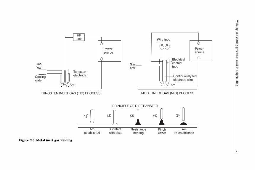
1 2 3 4 5
Pincheffect
Arcre-established
Contactwith plate
PRINCIPLE OF DIP TRANSFER
Resistanceheating
Arcestablished
Gasflow
Gasflow
Wire feed
Arc
Continuously fedelectrode wire
Electricalcontacttube
METAL INERT GAS (MIG) PROCESS
Coolingwater
TUNGSTEN INERT GAS (TIG) PROCESS
Tungstenelectrode
Arc
HFunit
Powersource
Powersource
Figure 9.6 Metal inert gas welding.
Weld
ingandcuttin
gprocesses
used
inshipbuild
ing
91

Initially aluminum accounted for most of the MIG welding, with argon being usedas the inert shielding gas. Much of the welding undertaken on aluminum deckhouses,and liquid methane gas tanks of specialized carriers, has made use of this process.Generally larger wire sizes and heavier currents have been employed in this work,metal transfer in the arc being by means of a spray transfer, i.e. metal droplets beingprojected at high speed across the arc. At low currents metal transfer in the arc israther difficult and very little fusion of the plate results, which has made the weldingof light aluminum plate rather difficult with the MIG/argon process. The introductionof the ‘pulsed arc’ process has to some extent overcome this problem and madepositional welding easier. Here a low-level current is used with high-level pulses ofcurrent that detach the metal from the electrode and accelerate it across the arc to givegood penetration.
Early work on the welding of mild steel with the metal inert gas process madeuse of argon as a shielding gas, but as this gas is rather expensive, and satisfactorywelding could only be accomplished in the downhand position, an alternativeshielding gas was sought. Research in this direction was concentrated on the use ofCO2 as the shielding gas, and the MIG/CO2 process is now widely used forwelding mild steel. Using higher current values with thicker steel plate a fine spraytransfer of the metal from the electrode across the arc is achieved, with a deeppenetration. Wire diameters in excess of 1.6 mm are used, and currents aboveabout 350 amps are required to obtain this form of transfer. Much of the highercurrent work is undertaken with automatic machines, but some semi-automatictorches are available to operate in this range in the hands of skilled welders.Welding is downhand only.
On thinner plating where lower currents would be employed, a different modeof transfer of metal in the arc is achieved with the MIG/CO2 process. This form ofwelding is referred to as the dip transfer (or short-circuiting) process. The sequence ofmetal transfer is (see Figure 9.6):
1. Establish the arc.2. Wire fed into arc until it makes contact with plate.3. Resistance heating of wire in contact with plate.4. Pinch effect, detaching heated portion of wire as droplet of molten metal.5. Re-establish the arc.
To prevent a rapid rise of current and ‘blast off’ of the end of the wire when it short-circuits on the plate, variable inductance is introduced in the electrical circuit. Smallerwire diameters, 0.8 and 1.2 mm, are used where the dip transfer method is employedon lighter plate at low currents. The process is suitable for welding light mild steelplate in all positions. It may be used in shipbuilding as a semi-automatic process,particularly for welding deckhouses and other light steel assemblies.
The pulsed MIG/argon process, developed for positional welding of lightaluminum plate, may be used for positional welding of light steel plate but is likely toprove more expensive.
Use of the MIG semi-automatic processes can considerably increase weld outputand lower costs.
92 Ship Construction

This form of welding may also be collectively referred to as MAGS welding, i.e.metal arc gas-shielded welding.
Plasma welding
This is very similar to TIG welding as the arc is formed between a pointed tungstenelectrode and the plate. But, with the tungsten electrode positioned within the body ofthe torch, the plasma arc is separated from the shielding gas envelope (see Figure 9.7).Plasma is forced through a fine-bore copper nozzle that constricts the arc. By varyingthe bore diameter and plasma gas flow rate, three different operating modes can beachieved:
1. Microplasma—the arc is operated at very low welding currents (0.1–15 amps) and used forwelding thin sheets (down to 0.1 mm thickness).
2. Medium current—the arc is operated at currents from 15 to 200 amps. Plasma welding is analternative to conventional TIG welding, but with the advantage of achieving deeperpenetration and having greater tolerance to surface contamination. Because of the bulkinessof the torch, it is more suited to mechanized welding than hand welding.
3. Keyhole plasma—the arc is operated at currents above 100 amps and by increasing theplasma flow a very powerful plasma beam is created. This can penetrate thicknesses up to 10mm, but when using a single-pass technique is normally limited to a thickness of 6 mm. Thisoperating mode is normally used for welding sheet metal (over 3 mm) in the downhandposition.
Nozzle
Shielding gas
Plate
Plasma gas
Tungsten electrode
Cooling water
Power source
+ve
–ve
Figure 9.7 Plasma welding.
Welding and cutting processes used in shipbuilding 93

Other welding processes
There are some welding processes that cannot strictly be classified as gas or arcwelding processes and these are considered separately.
Electro-slag welding
The electro-slag welding process is used for welding heavy casting structurecomponents such as stern frames and was also used at an earlier stage to make verticalwelds in heavier side shell when fabricated hull units where joined at the berth. Withthe development of the electro-gas welding process, electro-slag welding is no longerused for the latter purpose.
To start the weld an arc is struck, but welding is achieved by resistance path heatingthrough the flux, the initial arcing having been discouraged once welding is started. InFigure 9.8 the basic electro-slag process is illustrated; the current passes into the weldpool through the wire, and the copper water-cooled shoes retain the molten pool ofweld metal. These may be mechanized so that they move up the plate as the weld iscompleted, flux being fed into the weld manually by the operator. A square edgepreparation is used on the plates, and it is found that the final weld metal has a highplate dilution. ‘Run-on’ and ‘run-off’ plates are required for stopping and starting theweld, and it is desirable that the weld should be continuous. If a stoppage occurs itwill be impossible to avoid a major slag inclusion in the weld, and it may then benecessary to cut out the original metal and start again. If very good weld properties arerequired with a fine grain structure (electro-slag welds tend to have a coarse grainstructure) it is necessary to carry out a local normalizing treatment.
Electro-gas welding
Of greater interest to the shipbuilder is a further development, electro-gas welding (seeFigure 9.8). This is in fact an arc welding process that combines features of gas-shielded welding with those of electro-slag welding. Water-cooled copper shoessimilar to those for the electro-slag welding process are used, but a flux-cored wirerather than a bare wire is fed into the weld pool. Fusion is obtained by means of an arcestablished between the surface of theweld pool and thewire, and the CO2 or CO2withargon mixture gas shield is supplied from separate nozzles or holes located centrallynear the top of the copper shoes. The system is mechanized utilizing an automaticvertical-up welding machine fed by a power source and having a closed-loop coolingcircuit and a level sensor that automatically adjusts the vertical travel speed.
The process is more suitable for welding plates in the thickness range of 13–50 mmwith square or vee edge preparations and is therefore used for shipbuilding purposesin the welding of vertical butts when erecting side shell panels or for the vertical shellbutt joints when joining building blocks on the berth or dock. For this purpose the useof a single- or double-vee butt with the electro-gas process is preferable since thispermits completion of the weld manually if any breakdown occurs. A square butt withappreciable gap would be almost impossible to bridge manually.
94 Ship Construction

Laser welding
Laser welding is being used in the shipbuilding industry and shows much promise asa welding process that offers low heat input and therefore minimum distortion ofwelded plates and stiffeners.
For shipbuilding welding applications the laser source is either CO2 (see ‘Lasercutting’ section below) or Nd:YAG (neodimium–yttrium–aluminum–garnet) crystals.Because of the wide range of applied powers and power densities available from
Wire fed into pool
Weld poolSlag
ELECTRO-SLAGWELDING
Moltenmetal
Coolingwater
Welddirection
IN
OUT
Coppershoe
Completedweld
Wire guide nozzle
Water-cooledcopper shoe
Weld
ELECTRO-GASWELDING
CO2
Wirefeed
Arc
Electrodewire
CO2
Figure 9.8 Electro-gas and electro-slag welding.
Welding and cutting processes used in shipbuilding 95

Nd:YAG lasers, different welding methods are possible. If the laser is in pulsed modeand the surface temperature is below boiling point, heat transfer is predominantly byconduction and a conduction limited weld is produced. If the applied power is higher(for a given speed), boiling begins in the weld pool and a deep penetration weld can beformed. After the pulse, the material flows back into the cavity and solidifies. Boththese methods can be used to produce spot welds or ‘stake’ welds. Laser ‘stakewelding’ has been used in shipbuilding, stiffening members being welded to platepanels from the plate side only. A seam weld is produced by a sequence of over-lapping deep penetration ‘spot’ welds or by the formation of a continuous moltenweld pool. Pulsed laser welding is normally used at thicknesses below about 3 mm.Higher power (4 to 10 kW) continuous-wave Nd:YAG lasers are capable of keyhole-type welding materials from 0.8 to 15 mm thickness. Nd:YAG lasers can be used ona wide range of steels and aluminum alloys. Also, because of the possibility of usingfiber-optic beam delivery, Nd:YAG lasers are often used in conjunction with articu-lated arm robots for welding fabricated units of complex shape. Since the beam canburn the skin or severely damage the eyes, Nd:YAG lasers require enclosures withinthe fabrication shop that are fully opaque to the Nd:YAG laser wavelength.
Hybrid laser–arc welding is also used in the shipbuilding industry, this beinga combination of laser and arc welding that produces deep penetration welds withgood tolerance to poor joint fit-up. The Nd:YAG laser is combined with a metal arcwelding gas (laser-MAG).
Thermit welding
This is a very useful method of welding that may be used to weld together large steelsections, for example parts of a stern frame. It is in fact often used to repair castings orforgings of this nature. Thermit welding is basically a fusion process, the required heatbeing evolved fromamixture of powdered aluminumand ironoxide.The endsof the partto bewelded are initially built into a sand or graphite mold, whilst the mixture is pouredinto a refractory lined crucible. Ignitionof thismixture is obtainedwith the aid of a highlyinflammable powder consisting mostly of barium peroxide. During the subsequentreaction within the crucible the oxygen leaves the iron oxide and combines with thealuminum producing aluminum oxide, or slag, and superheated thermit steel. This steelis run into themold,where it preheats and eventually fuses andmixeswith the ends of theparts to be joined. On cooling a continuous joint is formed and the mold is removed.
Friction stir welding1
Friction stir welding is a relatively new materials joining process that has been used inthe shipbuilding industry and is likely to be more widely used.
Friction stir welding is a solid-state process that offers advantages over fusionwelding for certain applications. In producing butt joints it uses a nonconsumablerotating tool, the profiled pin of which is plunged into the butted joint of two plates
1 Friction stir welding was invented and patented by TWI Ltd., Cambridge, UK.
96 Ship Construction

and then moves along the joint. The plate material is softened in both plates andforced around the rotating profiled pin, resulting in a solid-state bond between the twoplates (see Figure 9.9). To contain the softened material in the line of the joint,a backing bar is used and the tool shoulder under pressure retains material at the uppersurface. Both plates and the backing bar require substantial clamping because of theforces involved. Plates of different thickness may be butt welded by inclining therotating tool (Figure 9.9).
The process is currently used for welding aluminum alloy plates and such plates toaluminum alloy extrusions or castings. Dissimilar aluminum alloys may be joined bythe process. A suitable material for a rotating tool to permit friction stir welding ofsteel has yet to be developed.
Typical applications of friction stir welding are the construction of aluminum alloydeck panels for high-speed craft from extruded sections and aluminum alloyhoneycomb panels for passenger ship cabin bulkheads.
Downward force
Movementof tool
Rotationof tool
Shoulder
Probe
Retreating sideof weld
Shoulder
Height abovebacking bar
Probe Workpiece
Advancing sideof weld
Tool
Figure 9.9 Friction stir welding.
Welding and cutting processes used in shipbuilding 97
Cutting processes
Steel plates and sections were mostly cut to shape in shipyards using a gas cuttingtechnique, but the introduction of competitive plasma-arc cutting machines has led totheir widespread use in shipyards today.
Gas cutting
Gas cutting is achieved by what is basically a chemical/thermal reaction occurringwith iron and iron alloys only. Iron or its alloys may be heated to a temperature atwhich the iron will rapidly oxidize in an atmosphere of high purity oxygen.
The principle of the process as applied to the cutting of steel plates and sections inshipbuilding is as follows. Over a small area the metal is preheated to a given temper-ature, and a confined stream of oxygen is then blown onto this area. The iron is thenoxidized in a narrow band, and the molten oxide and metal are removed by the kineticenergy of the oxygen stream. A narrow parallel sided gap is then left between the cutedges. Throughout the cutting operation the preheat flame is left on to heat the top of thecut since most of the heat produced by the reaction at the cutting front is not instanta-neous, and tends to be liberated at the lower level of the cut only. Alloying elements insmall amounts are dissolved in the slag and removed when cutting steel. However, ifthey are present in large quantities, alloying elements, especially chromium, will retardand evenprevent cutting. The reason for this is that they either decrease thefluidity of theslag or produce a tenacious oxide film over the surfacewhich prevents further oxidationof the iron. This may be overcome by introducing an iron rich powder into the cuttingarea, a process often referred to as ‘powder cutting’.When cutting stainless steels whichhave a high chromium content ‘powder cutting’ would be employed.
Generally acetylene is used with oxygen to provide the preheat flame but othergases can be used: propane for example or hydrogen which is used for underwaterwork because of its compressibility. Apart from the torch, the equipment is similar tothat for gas welding. The torch has valves for controlling the volume of acetylene andoxygen provided for the preheat flame, and it has a separate valve for controlling theoxygen jet (see Figure 9.10).
The oxyacetylene cutting process has been highly automated for use in shipyards;these developments are considered in Chapter 13. Hand burning with an oxyacetyleneflame is used extensively for small jobbing work, and during the fabrication anderection of units.
Plasma-arc cutting
Plasma in this sense is a mass of ionized gas which will conduct electricity. Anelectrode is connected to the negative terminal of a DC supply and a gas shield issupplied for the arc from a nozzle which has a bore less than the natural diameter ofthe arc. As a result a constricted arc is obtained which has a temperature consid-erably higher than that of an open arc. The arc is established between the electrodeand workpiece when the ionized conducting gas comes into contact with the work.
98 Ship Construction

+
Preheating flamemixture
Oxygen cutting jet
Torch nozzle
Cut direction
Mild steel plate
OXYACETYLENE CUTTING
Side of kerf
Tungsten electrode
Water-coolednozzle
Plate
Constrictedarc
Plasmagas
PRINCIPLE OF PLASMACUTTING TORCH
Oxygen supply
Coating
ElectrodeDirection of
cut
Surface preheatedby arc
Combustion zone
ARC-AIR GOUGING
PLAN
ELEVATION
PlateBevel cut
BURNING HEAD WITH THREE NOZZLES FORPREPARING PLATE EDGE BEVELS
1
1
2
2
3
3
30° 30°
VE
VE
Figure 9.10 Metal cutting processes.
Weld
ingandcuttin
gprocesses
used
inshipbuild
ing
99

This gas is ionized in the first place by a subsidiary electrical discharge between theelectrode and the nozzle. Plates are cut by the high-temperature concentrated arcmelting the material locally (Figure 9.10).
The plasma-arc process may be used for cutting all electrically conductivematerials. Cutting units are available with cutting currents of 20–1000 amps to cutplates with thicknesses of 0.6–150 mm. The plasma carrier gas may be compressedair, nitrogen, oxygen, or argon/hydrogen to cut mild or high alloy steels, andaluminum alloys, the more expensive argon/hydrogen mixture being required to cutthe greater thickness sections. A water-injection plasma-arc cutting system is avail-able for cutting materials up to 75 mm thick using nitrogen as the carrier gas. A highercutting speed is possible and pollution minimized with the use of water and anexhaust system around the torch.
Water cutting tables were often used with plasma-arc cutting, but more recentsystems have dispensed with underwater cutting. Cutting in water absorbed the dustand particulate matter and reduced the plasma noise and ultraviolet radiation of earlierplasma cutters.
Gouging
Both gas and arc welding processes may be modified to produce means of gouging outshallow depressions in plates to form edge preparations for welding purposes whereprecision is not important. Gouging is particularly useful in shipbuilding for cleaningout the backs of welds to expose clean metal prior to depositing a weld back run. Thealternative to gouging for this task is mechanical chipping, which is slow and arduous.Usually, where gouging is applied for this purpose, what is known as ‘arc-air’ gougingis used. A tubular electrode is employed, the electrode metal conducting the currentand maintaining an arc of sufficient intensity to heat the workpiece to incandescence.Whilst the arc is maintained, a stream of oxygen is discharged from the bore of theelectrode that ignites the incandescent electrode metal and the combustible elementsof the workpiece. At the same time the kinetic energy of the excess oxygen removesthe products of combustion, and produces a cut. Held at an angle to the plate, theelectrode will gouge out the unwanted material (Figures 9.8, 9.10).
A gas cutting torch may be provided with special nozzles that allow gouging to beaccomplished when the torch is held at an acute angle to the plate.
Laser cutting
Profile cutting and planing at high speeds can be achievedwith a concentrated laser beamand has increasingly been employed in amechanized or robotic form in the shipbuildingindustry in recent years. In a laser beam the light is of onewavelength, travels in the samedirection, and is coherent, i.e. all the waves are in phase. Such a beam can be focused togive high energy densities. For welding and cutting the beam is generated in a CO2 laser.This consists of a tube filled with a mixture of CO2, nitrogen, and helium that is made tofluoresce by a high-voltage discharge. The tube emits infrared radiation with a wave-length of about 1.6 mm and is capable of delivering outputs up to 20 kW.
100 Ship Construction

Laser cutting relies on keyholing to penetrate the thickness, and the molten metalis blown out of the hole by a gas jet. A nozzle is fitted concentric with the output froma CO2 laser so that a gas jet can be directed at the work coaxial with the laser beam.The jet can be an inert gas, nitrogen, or in the case of steel, oxygen. With oxygen thereis an exothermic reaction with the steel, giving additional heat as in oxy-fuel cutting.The thermal keyholing gives a narrow straight-sided cut compared with the normalcut obtained by other processes relying on a chemical reaction.
Water jet cutting
The cutting tool employed in this process is a concentrated water jet, with or withoutabrasive, which is released from a nozzle at 2½ times the speed of sound and ata pressure level of several thousand bar. Water jet cutting can be used on a range ofmaterials such as timber, plastics, rubber, etc., as well as steels and aluminum alloys.Mild steel from 0.25 to 150 mm in thickness and aluminum alloys from 0.5 to 250 mmin thickness can be cut. Being a cold cutting process the heat-affected zone,mechanical stresses, and distortion are left at the cut surface.
Water jet cutting is slower than most thermal cutting processes and is not a portablemachine tool.
Further reading
ESAB advances in welding and cutting technology, The Naval Architect, July/August 2003.Exploiting friction-stir welding of aluminium, The Naval Architect, July/August 2004.Modern materials and processes for shipbuilding, The Naval Architect, July/August 2005.Smith BD: Welding Practice, 1996, Butterworth Heinemann.
Some useful websites
http://www.rina.org.uk/tna.html Site for The Naval Architect magazine, with regular updateson ship and shipbuilding technology, including welding.
www.esab.com Recommended for informative papers on welding processes and practices.www.controlwaterjet.co.uk Use, benefits, and capabilities of water jet cutting.
Welding and cutting processes used in shipbuilding 101

10 Welding practice and testingwelds
Chapter OutlineWelding practice 103Welding automation 105Welding distortion 107Welding sequences 107Testing welds 110
Weld faults 110Nondestructive testing 112Classification society weld tests 114Further reading 115Some useful websites 115
The strongest welded joint that may be produced in two plates subsequently subjectedto a tensile pull is the butt joint. A butt joint is one where the two joined plates are inthe same plane, and in any welded structure it is desirable that butt joints should beused wherever possible.
In mild steel the weld metal tends to have a higher yield strength than the platematerial (see Figure 10.1). Under tension it is found that initial yielding usuallyoccurs adjacent to a butt weld in the plate when the yield strength of the plate materialis reached locally. Since a good butt weld in tension has a strength equivalent to thatof the mild steel plate, it is not considered as a line of structural weakness.
Lapped joints, where fillet welds are used to connect the plates, should be avoided instrength members of a welded structure. As the fillet welds are in shear when the platesare in tension, the strength of the joint is verymuch less than that of the platematerial orbutt joint. Fillet welds are unavoidable where sections or plates are connected at anangle to an adjacent plate, but often there is not the same problem as the loading isdifferent. The fatigue strength of fillet welds is also inferior to that of a butt weld.
Welding practice
In making a butt weld with manual arc welding, where the plate thickness exceeds,say, 5–6 mm it will become necessary to make more than one welding pass to depositsufficient weld metal to close the joint. With the higher current automatic welding
Ship Construction. DOI: 10.1016/B978-0-08-097239-8.00010-6
Copyright � 2012 Elsevier Ltd. All rights reserved.

( )
Mild steel plate
TYPICAL MILD STEELSTRESS/STRAIN RELATIONSHIPOF PARENT AND WELD METAL
Weldyieldstress
Plateyieldstress
Strain
Str
ess
(P/A
)
l
Weld metal
l
Full penetration
ReinforcementMulti-run weld madeto obtain penetration
Back run
BUTT WELD
Leglength
1
2 3
4 5
Leglength
FILLET WELD
Throa
t Ideally 45°
Width
Figure 10.1 Stress–strain relationship for parent/weld metals and butt/fillet weld detail.
104 Ship Construction

processes thicker plates may be welded with a single pass, but at greater thicknessesmulti-pass welds become necessary.
In ship work unless a permanent backing bar is used, or a ‘one-sided’ weldingtechnique or process (see Chapter 9) is used, a back run of weld is required to ensurecomplete weld penetration. This is made on the reverse side of the joint after cleaningout the slag, etc., by chipping or gouging. Permanent backing barsmay conveniently beintroduced where it is desired toweld from one side only during erection at the berth. Agood example is the use of a cut-down channel bar used as a deck beam, the upperflange providing the backing bar for a deck panel butt weld, made by machine above.
Tack welds are used throughout the construction to hold plates and sections inplace after alignment and prior to completion of the full butt or fillet weld. These areshort light runs of weld metal, which may be welded over, or cut out in more criticaljoints during the final welding of the joint.
Fillet welds may be continuous or intermittent depending on the structuraleffectiveness of the member to be welded. Where fillets are intermittent they may beeither staggered or chain welded (see Figure 10.2), the member may also be scallopedto give the same result when continuously welded.
On thicker plates it becomes necessary to bevel the edges of plates that are to bebutted together in order to achieve complete penetration of the weld metal(Figure 10.2). This operation may be carried out whilst profiling or trimming the plateedges, which must be aligned correctly. Most edge preparations are made by gas orplasma heads having three nozzles out of phase that can be set at different angles togive the required bevels. Alternatively, the edge preparation may be obtained bymechanical machining methods using either a planing or milling tool. For very highquality welds in thick plate, particularly of the higher tensile types of steel,mechanical machining may well be specified. It is worth noting that there is little tochoose between the two as far as metallurgical damage goes, but mechanical methodsprovide a better finish.
Plates of varying thickness may be butt welded together at different locations,a good example being where heavy insert plates are fitted. Insert plates are preferredto doubling plates in welded construction, and the heavy plate is chamfered to thethickness of the adjacent thinner plate before the butt edge preparation is made.
To ease the assembly of welded units it is common practice to make use of what isknown as an ‘egg box’ construction. Within the double-bottom unit the floors and sidegirders may be slotted at their intersections so that they fit neatly together prior toconstruction.
Welding automation
Larger shipyards with a large production line throughput of welded panels useautomated welding systems to produce the stiffened panels. To join the plates, high-speed one-sided submerged arc welding (see Figure 9.4) is used. The requiredwelding parameters are set in advance in the operation box and linked to a computer.The operator selects the plate thickness and starts the machine. The machine
Welding practice and testing welds 105

60°
SQUARE
VEE
Nose
DOUBLEVEE
Heavy plate
Heavy plate
Heavy plate
Heavy plate
‘U’ BUTT
Plate 6mm–18mm thick
Plate less than 6mm thick (manual)
60°
60°60°
t
t
40°
40°
20°
20°
Backing bar
TAPER 1 IN 4
Tack weld
30 4°– 0°
30°
Greater than1.125t t
FILLET VEE
FILLET J
Not greaterthan 0.25Dor 75 mmwhicheveris less
LAP WELD (BAD PRACTICE) Fillet weld
TACK WELDS
Tack Tack Tack
STAGGERED INTERMITTENT FILLET WELDS
WeldWeld
Weld Weld Weld
Weld
CHAIN INTERMITTENT FILLET WELDS
SCALLOPED SECTION WITH CONTINUOUSFILLET
1/3t
1/3t
1/3t
1/3t
1/3t
1/3tRadius not less than 25 mm
150 mm max
D
60°
Figure 10.2 Plate edge preparation.
106
Ship
Constru
ction

automatically controls the welding parameters for the weld crater and stops when therun-off tab is reached at the end of the plates. The welded plate panel is then movedover floor-mounted rollers to the next stage where the stiffening members are to beattached. Each stiffener is lowered onto the plate panel and tack welded using metalarc gas-shielded welding. The plate panel with tacked stiffeners is then rolled withinreach of a fillet welding gantry with double-fillet welding machines. The gantrymoves parallel to the stiffeners at the same speed as the welding heads and carriespacks containing the welding wires and power sources for the double-fillet weldingheads. Welding is carried out using flux-cored wires with CO2 gas shielding.
The use of robotics for welding is referred to in Chapter 13.
Welding distortion
During the welding process the metal is heated, which causes expansion and the metalthen contracts on cooling. The initial rapid heating causes the welded area to expandlocally. The slower cooling of the weld causes the plate to move as the weld contracts.The result is a distortion of the part, and this is a major cause of extra work duringassembly of units and construction of the ship. The need to adjust distorted parts sothat they fit correctly can take considerable time and effort. In-plane distortion isbasically shrinkage of the plate. For repeatable processes, which are usual in ship-building, the shrinkage can be measured and sufficient data built up to allow theshrinkage to be predicted. Computer-aided design systems can now include anallowance for shrinkage, so that the part as modeled in the system can then beadjusted during the generation of cutting information. The plates are cut oversizedand the shrinkage after welding brings it to the correct size. More recently, work hasbeen carried out to model shrinkage of more complex parts, for example structuralwebs with face flats. Again, these parts can then have their dimensions adjusted priorto cutting so that the effect of shrinkage is to bring them to the correct shape. Out-of-plane distortion is much more difficult to predict and manage. The cause is the sameas in-plane shrinkage, but the distortion is often associated with fillet welds used toattach stiffeners to plates. The fillet welds, as they shrink, pull the plate out of plane,resulting in the typical appearance of a welded hull with indentations between theframes. The effect is much more noticeable for thin plate structures, for smaller ships,and for superstructures. Restraining the plate during assembly and welding is onecommonly used solution.
The causes of distortion are complex and also include any residual stresses in thesteel plate as a result of the steel mill rolling and cooling. Some of the stress may berelieved by rolling the plate prior to production, but distortion remains a significantproblem for many shipbuilders.
Welding sequences
In order to minimize distortion in manual welding the ‘backstep’ and ‘wandering’methods of welding are often used, the length of each step being the amount of weld
Welding practice and testing welds 107

metal laid down by an electrode to suit the required cross-section of weld(see Figure 10.3).
To reduce distortion and limit the residual stresses in the structure it is importantthat a correct welding sequence should be utilized throughout the construction.This applies both during the fabrication of units and at erection and joining onthe berth.
Of the more important welds in the construction of the ship the sequencesinvolving welding of butts and seams in plating panels may be considered (seeFigure 10.4). At T intersections it is necessary to weld the butt first fully, then gouge
BACKSTEP METHOD OF WELDING
Direction of weld
Direction of weld
Direction of weld
Direction of weld
6
6
5
4
4
2
3
5
2
3
1
1
1
1
2
3
3
5
4
2
5
4
6
6
Progression of welder
Progression of welder
Progression of welder
Progression of welder
WANDERING METHOD OF WELDING
WELD DISTORTION
Weld direction
Shrinkagestresses
Figure 10.3 Backstep and wandering methods of welding.
108 Ship Construction
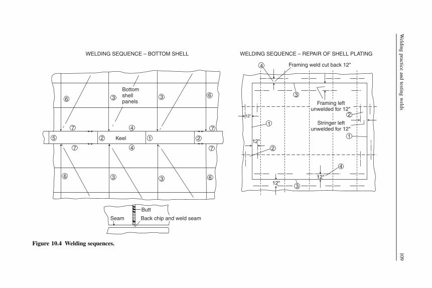
Seam
Butt
Back chip and weld seam
WELDING SEQUENCE – BOTTOM SHELL
6
7
3
4
3 6
7
2125
7
6
4
3 3 6
7
1
3
4
2
1
2
4
3
Bottomshellpanels
Keel
WELDING SEQUENCE – REPAIR OF SHELL PLATING
Framing weld cut back 12"
Framing leftunwelded for 12"
Stringer leftunwelded for 12"
12"
12"
12"
12"
Figure 10.4 Welding sequences.
Weld
ingpractice
andtestin
gweld
s109

out the ends to renew the seam edge preparation before welding the seam. Weldingthe seam first would cause high restraint across the plate strake and when the butt wasfinished a crack might occur. General practice when welding shell panels is to start bywelding the central butts and then adjacent seams, working outwards both trans-versely and longitudinally. Ships’ structural panels have various forms of stiffenerattached to the plate panels, these generally being welded to the panel aftercompleting the welding of the panel plates. These stiffening members are leftunwelded across the butts and seams of the plates until these are completed, if they areattached at some intermediate stage.
Erection welding sequences generally follow the principles laid down for platingpanels. In welded ships the lower side plating seams should not be welded before theupper seams, particularly the deck and gunwale seams. If this sequence of welding theside shell were adopted the upper portion of the hull structure would tend to beshortened, causing the hull to rise from the blocks at the ends. Where in modernconstruction the side shell and deck plating are erected in blocks and a suitablewelding sequence is employed, this problem does not arise.
In repair work correct welding sequences are also important, particularly wherenew material is fitted into the existing relatively rigid structure. Again, the procedurefollows the general pattern for butts and seams in plate panels. If a new shell plate isto be welded in place the seams and butts in the surrounding structure are cut back300–375 mm from the opening, likewise the connection of the stiffening in way of theopening.
The inserted plate panel is then welded to within 300–375 mm of the free edges,the butts are completed, and then the seams after welding any longitudinal stiffeningacross the butts. Finally, the vertical framing is welded in way of the seams(Figure 10.4).
Testing welds
For economic reasons much of the weld testing carried out in shipbuilding is donevisually by trained inspectors. Spot checks at convenient intervals are made on themore important welds in merchant ship construction, generally using radiographic orultrasonic equipment. Welding materials are subjected to comprehensive tests beforethey are approved by Lloyd’s Register or the other classification societies for use inship work. Operatives are required to undergo periodical welder approval tests toascertain their standard of workmanship.
Weld faults
Various faults may be observed in butt and fillet welds. These may be due to a numberof factors: bad design, incorrect welding procedure, use of wrong materials, and badworkmanship. Different faults are illustrated in Figure 10.5. The judgment of theseriousness of the fault rests with the weld inspector and surveyor, and where the weldis considered to be unacceptable it will be cut out and rewelded.
110 Ship Construction

OVERLAP
UNDERCUT
LACK OFREINFORCEMENT
LACK OF PENETRATION
LACK OF FUSION
EXCESSIVEREINFORCEMENT
LAMELLARTEARING
CRATER CRACKS
Resultingpull-out
Lamellar tear in nonmetallic stringer
INADEQUATE CROSS-SECTION
UNDERBEAD CRACKING
GAS ENTRAPMENT
Long cavities called ‘pipes’
SLAG INCLUSIONS
Inclusions between weld passesnot cleaned out
Root not properly backgouged
Small spherical cavitiescalled ‘porosity’
Figure 10.5 Weld faults.
Weld
ingpractice
andtestin
gweld
s111

Nondestructive testing
For obvious reasons some form of nondestructive test is required to enable thesoundness of ship welds to be assessed. The various available nondestructive testingmethods may be summarized as follows:
l Visual examinationl Dye penetrantl Magnetic particlel Radiographicl Ultrasonic.
Of these five methods, the dye penetrant and magnetic particle tests have fewapplications in ship hull construction, being used for examining surface cracks instern frames and other castings. Visual, radiographic, and ultrasonic examinations areconsidered in more detail, as they are in common use.
Magnetic particle testing is carried out by magnetizing the casting andspreading a fluid of magnetic particles (e.g. iron fillings suspended in paraffin) onthe surface. Any discontinuity such as a surface crack will show up as the particleswill concentrate at this point where there is an alteration in the magnetic field.A dye penetrant will also show up a surface flaw if it remains after the castinghas been washed following the application of the dye. To aid the detection ofa surface crack the dye penetrant used is often luminous and is revealed under anultraviolet light.
Visual inspection of welds is routine procedure, and surface defects are soonnoticed by the experienced inspector and surveyor. Incorrect bead shape, high spatter,undercutting, bad stop and start points, incorrect alignment, and surface cracks are allfaults that may be observed at the surface. Subsurface and internal defects are notobserved, but the cost of visual inspection is low, and it can be very effective whereexamination is made before, during, and after welding.
The principle of radiographic inspection is simply to subject a material to radiationfrom one side, and record the radiation emitted from the opposite side. Any obstaclein the path of the radiation will affect the radiation density emitted and may berecorded. As radiation will expose photographic plate, for all practical weld testpurposes this is used to record the consistency of the weld metal. The photographicplate records changes in radiation density emitted; for example, a void will show up asa darker shadow on the radiograph.
Either X-ray or gamma-ray devices may be used to provide the source of radiation.X-ray equipment consists of a high-voltage power source (50–400 kV), which is usedto provide potential between a cathode and target anode in a glass vacuum tube. Onlya small percentage of this energy is converted to X-rays, so that large amounts of heathave to be conducted away from the target. From the target the X-rays are projectedout of the tube onto the weld surface (see Figure 10.6).
Where gamma-ray devices are used ray emission is produced by decay ofa radioactive nucleus, the rate of emission being reduced with time. The radiationgiven off may be magnetically separated into three parts, a-rays, b-rays and g-rays,
112 Ship Construction
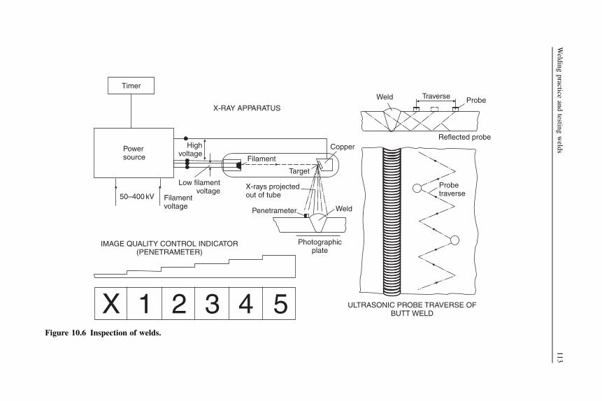
X 1 2 3 4 5
IMAGE QUALITY CONTROL INDICATOR(PENETRAMETER)
Powersource
50–400kV Filamentvoltage
Low filamentvoltage
Highvoltage
X-RAY APPARATUS
Filament
X-rays projectedout of tube
Penetrameter
Copper
Target
Weld
Photographicplate
Weld Traverse Probe
Reflected probe
ULTRASONIC PROBE TRAVERSE OFBUTT WELD
Probetraverse
Timer
Figure 10.6 Inspection of welds.
Weld
ingpractice
andtestin
gweld
s113

the g-rays being similar to X-rays and of most importance since they are verypenetrating, but this also means that heavy shielding is required. Since naturalradioactive sources are in short supply, great use is made of artificial radioactivesources, namely isotopes.
To interpret the weld radiograph a large amount of experience is required, anda sound knowledge of the welding process. Radiographs usually carry the image of an‘image quality indicator’, which shows the minimum change of thickness revealed bythe technique. This image quality indicator may have graded steps of metal, each stepbeing identified on the radiograph so that the minimum step thickness discernible isnoted and the sensitivity of the radiograph assessed. This indicator is placed adjacentto the weld prior to taking the radiograph.
Ultrasonic energy is commonly used as a tool for locating defects in welds, andhas several advantages over radiography, particularly as no health hazard isinvolved. The technique is particularly useful for locating fine cracks that are oftenmissed by radiography, particularly where they lie perpendicular to the emissionsource.
The principle of ultrasonic inspection depends on the fact that pulses of ultra-sonic energy are reflected from any surface that they encounter. Ultrasonic wavestraveling through a plate may be reflected from the surface of the metal and alsofrom the surfaces of any flaws that exist in the metal. Virtually total reflection occursat an air–metal interface, and therefore to get the ultrasonic wave into the metala liquid is placed between the source and metal. The pattern of reflection is revealedon a cathode ray tube, which may be calibrated using a standard reference block. Anexperienced operator is able to recognize flaws from the cathode ray tube display,and to some extent recognition of defect types is possible. Apart from weldinspection, ultrasonic techniques are valuable for assessing the thickness of struc-tural members.
Classification society weld tests
Classification societies specify a number of destructive tests that are intended to beused for initial electrode and weld material approval. These tests are carried out toascertain whether the electrode or wire-flux combination submitted is suitable forshipbuilding purposes in the category specified by the manufacturer.
Tests are made for conventional electrodes, deep penetration electrodes, wire-gasand wire-flux combinations, consumables for electro-slag and electro-gas welding,and consumables for one-sided welding with temporary backing. Tensile, bend, andimpact tests are carried out on the deposited weld metal and welded plate specimens.Other tests are made for the composition of the weld metal deposited and possiblecracking.
All works where electrodes, wire-flux and wire-gas combinations, consumablesfor electro-slag and electro-gas welding, and consumables for one-sided welding withtemporary backing are produced, and have been initially approved, are subject toannual inspection.
114 Ship Construction

Further reading
Boekholt R: Welding Mechanization and Automation in Shipbuilding Worldwide. AbingtonPublishing, 1996.
Some useful websites
www.esab.com Includes information on welding equipment.www.pemamek.fi See ‘Shipyards’ for details of welding/cutting automation and mechaniza-
tion, including robotics.
Welding practice and testing welds 115

11 Shipyard layout
Chapter OutlineFurther reading 123Some useful websites 124
Shipyards 124
Until the advent of steel ships, a shipbuilding operation could be set up almostanywhere close to the sea or a river and to trees for the main construction materials.Iron, rapidly followed by steel, construction resulted in shipbuilding moving to areaswhere raw materials, primarily coal and iron ore, were available. These were alsooften areas where the basic metalworking skills were to be found as the basis for thelabor force, or in some cases a labor force was moved into the area. Shipyards wereusually found along river banks, or in protected harbors, giving sheltered water andtheir basic arrangement did not vary. Figure 11.1 shows the typical arrangement ofa shipyard up to around 1960. The slipways on which the ships are constructed pieceby piece are supported by small and simple workshops. There was a relatively small
Figure 11.1 ‘Traditional’ riverside layout.
Ship Construction. DOI: 10.1016/B978-0-08-097239-8.00011-8
Copyright � 2012 Elsevier Ltd. All rights reserved.

initial investment and the output could be varied by opening or closing buildingslipways and taking on or laying off labor.
The layout of a shipyard did not vary significantly until the mid 1950s. A relativelysmall number of shipyards engaged in capital warship construction or passenger ships,where the product is significantly larger and more complex than average commercialships. These had extensive outfitting workshops and quays, as well as larger slipways.Large cranes, almost always fixed in position, were available to lift heavy items,perhaps 200 tonnes for large, complex ships. However, for the lifting of hull parts andmost outfitting the available lifting capacity was usually below 10 tonnes.
The major change in the shipyards came about initially because of rapid increasesin commercial ship size after 1950. At that time a typical cargo ship was of below10,000 deadweight tonnes, and a tanker of 20,000 deadweight tonnes was consideredlarge. By 1958, the first tanker over 100,000 deadweight tones was in operation andthe first over 200,000 tonnes deadweight by 1966. By 1970, 250,000-tonne and largerships were being built. An important aspect of these newer ships was a tenfoldincrease in steelweight, from a typical 3000 tonnes to 30,000 tonnes. Also, the largestships were in excess of 300 meters in length. As such, they were too large for mostexisting shipyards’ slipways and the lifting capacities of the small cranes usuallyavailable would have meant an excessive construction time.
The result was first that existing shipyards reduced the number of slipways andincreased the size of their cranes as the ship size increased. This allowed them toconstruct the ships in a shorter time, so keeping the construction time acceptable.A very few European shipyards increased the slipway sizes and cranes to be able tobuild VLCCs. However, the 1960s saw the emergence of a substantial number of newshipyards, primarily in Asia but also in Europe, which were purpose designed for thenew, large ships. The basic arrangement was established by the mid 1960s in Japan,and many shipyards built subsequently, including in Eastern Europe, and morerecently in South Korea, China and now Vietnam, have been specifically planned toconstruct the larger ships. The contemporary shipbuilding practices and productionmethods have improved but the basic technology and main equipment has beenconsistent for the last half century.
A number of traditional shipbuilders, which were often based on river banks, alsoestablished new yards where they could build larger ships and/or exploit the newtechnology and production methods. In general, the smaller shipbuilders have beenable to reconfigure their site in order to utilize new technology and improveproduction, whilst continuing to build smaller and medium-sized ships. In many casesthe shipyards are constrained as to the size and type of ship that can be built. Manysmaller shipyards have adopted total undercover construction, providing a dry, warm(or cool) environment. Undercover ship construction has been extended to somelarger ships, including many military ships and also passenger ships, especially inNorthern Europe. As in the early days of such large ships, where the shipyardsdiffered from the routine, the complexity and cost of the ship can justify the massivecapital expenditure on covered facilities.
An ideal layout for a modern shipyard is based on a production flow basis, as inFigure 11.2, with the shipyard built on a greenfield site and no longer, as with existing
120 Ship Construction
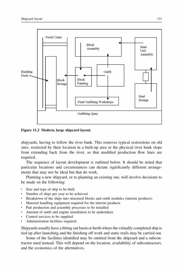
shipyards, having to follow the river bank. This removes typical restrictions on oldsites, restricted by their location in a built-up area or the physical river bank slopefrom extending back from the river, so that modified production flow lines arerequired.
The sequence of layout development is outlined below. It should be noted thatparticular locations and circumstances can dictate significantly different arrange-ments that may not be ideal but that do work.
Planning a new shipyard, or re-planning an existing one, will involve decisions tobe made on the following:
l Size and type of ship to be builtl Number of ships per year to be achievedl Breakdown of the ships into structural blocks and outfit modules (interim products)l Material handling equipment required for the interim productsl Part production and assembly processes to be installedl Amount of outfit and engine installation to be undertakenl Control services to be suppliedl Administration facilities required.
Shipyards usually have a fitting out basin or berth where the virtually completed ship istied up after launching and the finishing off work and static trails may be carried out.
Some of the facilities identified may be omitted from the shipyard and a subcon-tractor used instead. This will depend on the location, availability of subcontractors,and the economics of the alternatives.
Figure 11.2 Modern, large shipyard layout.
Shipyard layout 121

Before considering the actual layout of the shipyard, it is as well to consider therelationship of the work processes involved in building a ship, as illustrated inFigure 11.3.
An idealized layout of a new shipyard is indicated in Figure 11.4, which might beappropriate for a smaller yard specializing in one or two standard type ships witha fairly high throughput so that one covered building dock or berth is sufficient.
At this point it may be convenient to mention the advantages and disadvantages ofbuilding docks as opposed to building berths. Building docks can be of advantage inthe building of large vessels where launching costs are high, and there is a possibilityof structural damage owing to the large stresses imposed by a conventional launch.They also give good crane clearance for positioning units. The greatest disadvantageof the building dock is its high initial cost. However, the dock is the usual choice fornew shipyards, especially for larger ships. The level base simplifies the constructionprocess, for example alignment of structural blocks. Also, the dock is more flexible inoperation, for example in some cases ships are built in two stages with the outfit and
Platestowage
Sectionstowage
Shot-blast/prime Shot-blast/prime
CuttingMarkingShaping
Bendingcutting
Sub-assemblies
Panelassemblies
Matrixassemblies
Curvedunit
assemblies
Blockassembly
Block and uniterection
Final outfit
Outfitpalletization
andmodules
Outfitfabrication
and assembly
Pipe bending
Outfit materialsand bought in
items
Figure 11.3 Shipbuilding process.
122 Ship Construction

labor-intensive stern, containing machinery and accommodation, built as a singlestructure, then moved along the dock for the cargo-carrying part to be constructed.This doubles the available time for outfitting the ship.
Further reading
Brand-new Portsmouth complex for VT: The Naval Architect, July/August 2003.Chinese shipbuilders on the way to the top: The Naval Architect, September 2005.Covered hall benefit for Bijlsma: The Naval Architect, May 2002.The Naval Architect (published by the RINA) regularly carries articles on shipbuilding
developments.
Plate and section stockyard
Adminoffices
Marshaling and preparation
Platesection
andmachining
Moduleassembly
Unitassembly areas
and palletpreparation
Block fabrication Pipe andengine shop
Coveredbuildingdock
Outfitshops
Fitting outbasin
Figure 11.4 Shipyard layout.
Shipyard layout 123

Some useful websitesShipyardshttp://www.stxons.com/service/kor/main.aspx STX is a major group in Korea and Europe. The
site includes virtual shipyard tours explaining the process used.www.shi.samsung.co.kr Take the virtual tour of the Geoje Shipyard. Building large ships on
a new site with building docks.http://www.baesystems.com/Sites/SurfaceShips/ Has information on UK military ship
construction.http://www.fsg-ship.de/198-1-latest-videos.html Shows construction of mainly ro-ro ships on
a modernized, covered slipway.
124 Ship Construction

12 Design information forproduction
Chapter OutlineShip drawing office 126
Lines plan 126Three-dimensional representation of shell plating 128Shell expansion 128
Loftwork following drawing office 12810:1 scale lofting 130
Computer-aided design (CAD)/computer-aided manufacturing (CAM) 130Ship product model 131
Further reading 134Some useful websites 134
In order to produce a ship, it is necessary to develop the initial structural andarrangement design into information usable by production. While the initial design isfocused on the operation of the ship once completed, production requires informationin a form that relates to the manufacturing, assembly, and construction processes.Historically, this was done by creating a full-size model of the structure, in the moldloft, from which dimensions could be lifted and templates could be made. Therelatively simple outfitting of early ships was carried out on the completed shipstructure with pipes and other connectors run where space was available. Larger, morecomplex ships, faster construction times and cost have made this process obsolete,and it has largely been replaced by computer modeling.
This chapter briefly outlines the original functions of the ship drawing office andsubsequent full or 10:1 scale lofting of the hull and its structural components. It thenconcentrates on current use by shipyards of computer-aided design (CAD) for thesepurposes and the extensive use of computer-aided manufacturing (CAM) inshipbuilding.
In the past, the shipyard design office defined the principal ship dimensions, thescantlings for all major structure, specified major equipment, and satisfied all salu-tatory requirements. The drawing office developed the design by creating drawingsthat identified piece parts and critical dimensions. The mold loft then defined thedetailed, accurate geometry to manufacture hull piece parts for the ship structure andother trades defied the geometry for their own products, for example pipes andventilation trunking.
Ship Construction. DOI: 10.1016/B978-0-08-097239-8.00012-X
Copyright � 2012 Elsevier Ltd. All rights reserved.

The planning of production, the flow of material through the manufacturing stages,and the sequence of unit erection in the dock or slipway were determined by theproduction management.
Ship drawing office
The ship drawing office was traditionally responsible for producing detailed workingstructural, general arrangement, and outfit drawings for a new ship. It was also commonpractice for the drawing office to contain a material ordering department that wouldidentify the necessary material requirements from the drawings and progress them.
Structural drawings prepared by the drawing office would be in accordance withLloyd’s or other classification society rules and subject to their approval; also,owner’s additional requirements and standard shipyard practices would be incorpo-rated in the drawings. General arrangements of all the accommodation and cargospaces and stores would also be prepared, incorporating statutory requirements aswell as any shipowner’s requirements and standards. Outfit plans including pipingarrangements, ventilation and air-conditioning (which may be done by an outsidecontractor), rigging arrangements, furniture plans, etc. were also prepared. Two plansof particular significance were the ship’s ‘lines plan’ and ‘shell expansion’.
Lines plan
A preliminary version of this was, in effect, prepared at the time of the conceptualdesign to give the required capacity, displacement, and propulsive characteristics. Itwas subsequently refined during the preliminary design stage and following any tanktesting or other method of assessing the hull’s propulsive and seakeeping character-istics. The lines plan is a drawing, to a suitable scale, typically 1:100, of the moldedlines of the vessel in plan, profile, and section. Transverse sections of the vessel atequally spaced stations between the after and forward perpendiculars are drawn toform what is known as the body plan. Usually, 10 equally spaced sections are selectedwith half ordinates at the ends where a greater change of shape occurs. A halftransverse section only is drawn since the vessel is symmetrical about the center line,and forward half sections are drawn to the right of the center line with aft half sectionsto the left. Preliminary body plans are drawn initially to give the correct displacement,trim, capacity, etc., and must be laid off in plan and elevation to ensure fairness of thehull form. When the final faired body plan is available the full lines plan is completed,showing also the profile or sheer plan of the vessel and the plan of the waterline shapesat different heights above the base.
A lines plan is illustrated in Figure 12.1. The lines of the lateral sections in the sheerplan as indicated are referred to as ‘bow lines’ forward and ‘buttock lines’ aft. Bilgediagonalswould be drawnwith ‘offsets’ taken along the bilge diagonal to check fairness.
When the lines plan was completed manually the draughtsmen would compilea ‘table of offsets’, i.e. a list of half breadths, heights of decks and stringer, etc., ateach of the drawn stations. These ‘offsets’ and the lines plan were then passed to
126 Ship Construction

PLAN(waterlines)
AFT
A ABC
8 8½ 9 ½9 1 0
B
CButtocklines
Bowlines
Deck
L.W.L. L.W.L.
L.W.L.
12′
8′4′
Deck Deck
0 1 ½1½
PROFILE AFTPROFILE FORD
AFTSECTIONS
A A BB CC
54
32
1½
9½
8½
9
87
6 5
½1
0
10 FORDSECTIONS
L.W.L.
Deck
Deck
BODY PLAN
12′ L.W.L.
8′ L.W.L.
4′ L.W.L.
Deck
Figure 12.1 Lines plan.
Desig
ninform
ationforproductio
n127

loftsmen for full-size or 10:1 scale fairing. Since the original lines plan was ofnecessity to a small scale, which varied with the size of ship, the offsets tabulatedfrom widely spaced stations and the fairing were not satisfactory for buildingpurposes. The offsets used for building the ship would subsequently be lifted by theloftsman from the full size or 10:1 scale lines for each frame.
Three-dimensional representation of shell plating
When preparing the layout and arrangement of the shell plating at the drawing stage,it was often difficult to judge the line of seams and plate shapes with a conventionaltwo-dimensional drawing. Shipyards therefore made use of a ‘half block model’,which was in effect a scale model of half the ship’s hull from the center line outboard,mounted on a base board. The model was either made up of solid wooden sectionswith faired wood battens to form the exterior, or of laminated planes of wood faired asa whole. Finished with a white lacquer, the model was used to draw on the frame lines,plate seams and butts, lines of decks, stringers, girders, bulkheads, flats, stem andstern rabbets, openings in shell, bossings, etc.
Shell expansion
The arrangement of the shell plating taken from a three-dimensional model may berepresented on a two-dimensional drawing referred to as a shell expansion plan. Allvertical dimensions in this drawing are taken around the girth of the vessel ratherthan there being a direct vertical projection. This technique illustrates both the sideand bottom plating as a continuous whole. In Figure 12.2 a typical shell expansionfor a tanker is illustrated. This also shows the numbering of plates and lettering ofplate strakes for reference purposes, and illustrates the system where strakes ‘runout’ as the girth decreases forward and aft. This drawing was often subsequentlyretained by the shipowner to identify plates damaged in service. However, a word ofcaution is necessary at this point because since prefabrication became the acceptedpractice any shell expansion drawing produced will generally have a numberingsystem related to the erection of fabrication units rather than individual plates.Therefore, single plates were often marked in sequence to aid ordering andproduction identification.
Loftwork following drawing office
The mold loft in a shipyard was a large covered wooden floor area suitable for layingoff ship details at full size. The loft was usually located above the major hull steelworkshops, hence the term ‘loft’, and the practice originally derived from woodenshipbuilding.
When the loftsmen received the scale lines plan, and offsets from the drawingoffice, the lines would be laid off on the mold loft floor full size and then faired.Fairing was achieved by using wooden battens that were bent to follow the offsets,
128 Ship Construction

L
K
JSide
Bilge
Sheerstrake
plating
plating
H
GF
E
D1 D2 D3 D4 D5
C1 C9B11B10B9B8B7B6
Bottom A plating
Keel plate
FRAMING, STRINGERS, DECKS AND OPENINGS IN SIDE SHELL ARE ALSO SHOWN ON THESHELL EXPANSION BUT HAVE BEEN OMITTED FOR CLARITY
B5B4B3
C8C7C6C5C4C3C2
Figure 12.2 Shell expansion.
Desig
ninform
ationforproductio
n129

then held in place while the fair curve was inscribed on the wooden floor. This wouldmean using a great area of floor, even though a contracted sheer and plan werenormally drawn, and aft and forward body lines were laid over one another. Bodysections were laid out full size as they were faired to form what was known asa ‘scrieve board’.
The scrieve board was used for preparing ‘set bars’ (curvature to match plate) andbevels (to maintain the web of a ship frame perpendicular to the ship’s center line) forbending frames and for making templates and moldings for plates that requiredcutting and shaping.
Shell plates were developed (translating the curved shape into a flat plate thatwould later be cut and formed) full size on the loft floor and wooden templates madeso that these plates could be marked and cut to the right shape before fitting to theframing on the berth.
The mold loft in effect produced an accurate, full-scale, three-dimensional modelof the ship from which production information for the structure could be obtained.However, the process was labor intensive and relatively slow, and therefore expensive.Shipbuilders in Europe, where labor costs were higher, began development of alter-native methods to develop production information.
10:1 scale lofting
In the late 1950s the 10:1 lofting system was introduced and was eventually widelyadopted. This reduced the mold loft to a virtual drawing office and assisted in theintroduction of production engineering methods. Lines could be faired on a 10:1 scaleand a 10:1 scale scrieve board created. Many yards operated a flame profiling machine(see Chapter 13) that used 10:1 template drawings to control the cutting operation. Inpreparing these template drawings the developed or regular shape of the plates wasdrawn in pencil on to special white paper or plywood sheet painted white, and then theoutline was traced in ink on to a special transparent material. The material used wascritical, having to remain constant in size under different temperature and humidityconditions, and having a surface that would take ink without ‘furring’. Many of theoutlines of plates to be cut by the profiler could be traced directly from the scrieveboard, for example floors and transverses.
Computer-aided design (CAD)/computer-aidedmanufacturing (CAM)
The first technical use of computers in the shipbuilding industry occurred in the 1960sand because of the high costs involved was only used by the largest shipbuildersrunning programs developed in-house on a mainframe computer for naval architec-ture, including hydrostatics and powering calculations. The hull design was drawn byhand and stored on the computer as tables of offsets for use in the mold loft. Earlydevelopments for steel plate cutting and even frame bending were also seen in a fewshipyards in the 1960s.
130 Ship Construction

In the late 1970s the graphics terminal and the engineering workstation becamereadily available and could be linked to a mini computer. These computers costconsiderably less than the earlier mainframes, and commercial ship design andconstruction software became available for them. The larger shipyards quicklyadopted these systems. They developed further in the following two decades to run onUNIX workstations and Windows NT machines and have expanded to cover virtuallyall the computing needs of a large shipyard.
The early 1980s saw the appearance of the personal computer (PC) and severallow-cost software packages that performed simple hull design, hydrostatics, andpowering estimate tasks. These were popular with small shipyards and also reportedlywith some larger shipyards for preliminary design work. They were, however,somewhat limited and incompatible so that it was difficult to build a system thatcovered all the shipyard’s CAD/CAM requirements. During the 1990s the availablePC software standardized on hardware, operating systems, programming languages,data interchange file formats and hull geometry, and are now widely used by navalarchitects and the smaller ship and boat building industry in general.
Ship product model
Software systems for large shipbuilders are based on the concept of the ‘ship productmodel’ in which the geometry and the attributes of all elements of the ship derivedfrom the contract design and classification society structural requirements are stored.This model can be visualized at all stages and can be exploited to obtain informationfor production of the ship (see Figure 12.3).
At the heart of the ‘ship product model’ is the conceptual creation of the hull formand its subsequent fairing for production purposes, which is accomplished withoutcommitting any plan to paper. This faired hull form is generally held in the computersystem as a ‘wire model’, which typically defines the molded lines of all structuralitems so that any structural section of the ship can be generated automatically fromthe ‘wire model’. The model can be worked on interactively with other stored ship-yard standards and practices to produce detailed arrangement and working drawings.The precision of the structural drawings generated enables them to be used withgreater confidence than was possible with manual drawings and the materialsrequisitioning information can be stored on the computer to be interfaced with theshipyard’s commercial systems for purchasing and material control. Subassembly,assembly, and block drawings can be created in two- and three-dimensional form anda library of standard production sequences and production facilities can be called upso that the draughtsman can ensure that the structural design uses the shipyard’sresources efficiently and follows established and cost-effective practices. Weldlengths and types, steel weights, and detailed parts lists can be processed from theinformation on the drawing and passed to the production control systems. A three-dimensional steel assembly can be rotated by the draughtsman on screen to assess thebest orientation for maximum downhand welding.
The use of three-dimensional drawings is particularly valuable in the area of outfitdrawings where items like pipework and ventilation/air-conditioning trunking can be
Design information for production 131

‘sighted’ in the three-dimensional mode and more accurately measured before beingcreated in the two-dimensional drawing.
Stored information can be accessed so that lofting functions such as preparinginformation for bending frames and longitudinals, developing shell plates, and
Des
ign
Man
ufac
ture
Final linesplans
Hulldefinition
and designcalculations
Designdatabase
Conceptdesign
Generalarrangements
Ship’s database
3D wireship model
Material listsweights
centers ofgravity
Nestedformats
Shopdrawings
Productioncontrol
drawings
Modelintegration+ drawinggenerator
Interactiveparts
nesting
Longitudinalframe
development+ offsets
Develop-ment of
shellplates
Shellexpansion
Plate linebody plan
3Dsurface +
interrogationlines
fairing
Generationpreliminarylines to ship
database
Loadinginner
structuresurface
Loadingand fairingseams +
longitudinal
Standarddetails
Unitassemblymodels
Parts
NCtape
Nested formats
Drawingfile
Roll sets+ transverse
frameoffsets
Jigpin
heightsetc.
Interactiveparts coding
and assemblymodelbuilder
Fabricationdrawings
Structuraldrawings
Modelinterrogations
+ drawinggenerator
Software
Precodedrules –
proceduresbuilders
standards
Loadingstiffening
seams + buttscutouts
etc.
Figure 12.3 Ship product model.
132 Ship Construction

providing shell frame sets and rolling lines or heat-line bending information for platescan be done via the interactive visual display unit.
For a numerically controlled profiling machine the piece parts to be cut can be‘nested’, i.e. fitted into the most economic plate, which can be handled by the machinewith minimum wastage (see Figure 12.4). This can be done at the drawing stage whenindividual piece parts are abstracted for steel requisitioning and stored later, beingbrought back to the screen for interactive nesting. The order in which parts are to bemarked and cut can be defined by drawing the tool head around the parts on thegraphics screen. When the burning instructions are complete the cutting sequencemay be replayed and checked for errors. Instructions for cutting flame planed platesand subsequently joining them into panel assemblies and pin heights of jigs for settingup curved shell plates for welding framing and other members to them at the assemblystage can also be determined (see Figure 12.3).
The basic ship product model also contains software packages for the ship’s outfit,including piping, electrical and heating, ventilating and air-conditioning (HVAC)systems for a ship.
More recent developments have seen the hugely increased memory and processingcapability of computers harnessed to the ship product model. This now includes allthe hull structural information as well as outfitting. All pipes and other systemsinformation is available in the model. There is, as close as possible, a completerepresentation of the whole ship. This can then be developed into information for partproduction, cutting and forming, assembly instructions, material lists (bills ofmaterials), welding instructions, and quality assurance checks.
PARTS NESTING
DESIGN PARTS DEFINITION
PARTS LISTING
1
14
2
2
3
3
3
3
4
4
Figure 12.4 Assembly plate parts listing and nesting.
Design information for production 133

It is also now possible to combine the product model with virtual reality software.This enables visualization of a structure or a compartment within a ship, which canthen effectively be entered by the workforce. The work sequence, access require-ments, and other details can be developed so that the actual work process is plannedcompletely and production will proceed without any delays or mistakes.
Further reading
CAD/CAM Updates. These appear several times a year in the monthly publication The NavalArchitect. The Royal Institution of Naval Architects.
Metcalfe, The implementation of CAD in the shipbuilding industry. 79th Andrew LaingLecture, RINA/IMarEST (May 2011).
Torroja, Alonso, Developments in Computer Aided Ship Design and Production, The RoyalInstitution of Naval Architects, 1999.
Some useful websites
The following websites are those of a number of providers of software for ship designand construction purposes. They provide much more detail, graphic illustrations ofthe products, and other information than can be accommodated in a single chapter ofthis book.http://www.aveva.comwww.cadcam.autoship.comwww.cadmatic.comwww.foransystem.comwww.napa.fiwww.ShipConstructor.comwww.formsys.com
134 Ship Construction

13 Plate and section preparationand machining
Chapter OutlinePlate and section preparation 135
Stockyard 136Heating 137Plate leveling rolls (mangles) 137Shot-blasting 137Priming paint 137Plate handling in machine shops 138
Plate and section part preparation 138Plate profile cutting machines 138Planing machines 140Drilling machines 140Guillotines 140Presses 140Plate rolls 141Heat-line bending 142
Frame bending 143Cold frame bending 144Section profilers 144Robotics 144
Further reading 146Some useful websites 146
This chapter describes the processes that a plate or section undergoes from the time itis received into the shipyard until it is in its final shape ready to be welded into a unitof the ship structure. In recent years many changes have occurred in this sphere ofshipyard activity, and substantial economies can be achieved by obtaining an evenflow of production at this stage.
Plate and section preparation
For efficient ship production, the steel material must be in an ideal condition when itis ready to be processed, and its marshaling into order for production on arrival isessential to the efficiency of the shipbuilding process.
Ship Construction. DOI: 10.1016/B978-0-08-097239-8.00013-1
Copyright � 2012 Elsevier Ltd. All rights reserved.

Stockyard
On arrival at the shipyard, plates and sections are temporarily stored in thestockyard. In larger shipyards the stockyard is an uncovered space having sufficientarea to provide storage for enough plates and sections required for the working ofthe yard some months ahead. The stockyard is needed because the productionschedule of a steelmaker will not conform to the needs of one particular shipyard.Also, the shipyard may not be located near a steelmaker and may choose topurchase steel from another country if prices are lower. The stockyard ensuresthere is always steel to maintain production. In some cases the quantity of steel instorage might be about three months’ stock, but shipyards in countries that arenot substantial steel producers may find it necessary to carry much larger stocks ofmaterial. In contrast, Far East shipyards closely associated with and/or locatednear a steel manufacturer may carry as little as one month’s stock, and in somecases less.
When the plates and sections are ordered the steel mills are provided with details ofthe identification code for each item so that they may be marked. On arrival in thestockyard, since the coding is generally in terms of the unit structure for which eachitem is intended, it is convenient to store the plates and sections in their respectiveship and ship unit areas. In other words the material for each ship is allotted an area ofthe stockyard, this area being subdivided into plots for those items intended fora major structural fabrication block of the ship.
Smaller shipyards may choose to buy steel from a stockist, removing the need fora stockyard, which is an expensive facility. They may also standardize the steel platesused to reduce the need for marshaling. The ideal is ‘just in time’ delivery of steel,although some stock is kept as a buffer against delivery failures.
Material delivery and storage are controlled in accordance with production engi-neering practices to suit the ship’s construction program.
Steel plates are now stacked horizontally in piles as required. (It was oncecommon practice to store the plates vertically in racks, which was convenientfor weathering purposes, but steel is now treated prior to production.) Steelprofiles or sections are laid horizontally in convenient batches, usually by sizeand type.
Where cranes are used for material handling it is important that there be adequatecoverage for the full extent of the stockyard, and the material may be delivered to thecovered workshop areas. Craneage is generally of the electric overhead gantry type,traversing the stockyard on rails and extending into the workshop area; alternatively,the plates may be placed on a roller conveyor for delivery to the workshops. Lifts aremade with magnetic clamps for plates and slings for the sections; the crane capacitycan be up to 30 tonnes, to suit the material sizes that the shipyard can process. Platesrequired for the work being processed may be selected and stored adjacent toa conveyor and then transferred into the preparation workshop in the correctsequence.
The preparation begins with a conveyor system that transports the plates througha sequence of processes to bring it to a suitable condition for cutting.
136 Ship Construction

Heating
Usually, a water wash or gas heating system is provided that heats the plate ready forsubsequent paint drying. A wash system will also remove debris, and in some casessnow or ice.
Plate leveling rolls (mangles)
This is a set of plate-straightening rolls through which the plate is passed prior toits being worked. During production at the steelworks, the plates may acquirelocked-in stresses, which are released with the use of thermal processes in theshipyard. This can cause distortion, which slows production. Also, during transitto the shipyard, plates may become distorted, and for many of the modernmachining processes it is important that the plates should be as flat as practicable.Two sets of rolls may be provided, one for heavy plate and one for light plate,but types are now available that permit a wide range of thicknesses to bestraightened.
Shot-blasting
Plates and sections are in almost all cases now shot-blasted to remove rust andmillscale. The principles of shot-blasting are dealt with in Chapter 27.
Shot-blasting plant in shipyards is generally of the impeller wheel type, where theabrasive is thrown at high velocity against the steel surface and may be recirculated.The plant is installed so that the plate may pass through in the horizontal position,which allows the use of automated, roller conveyor systems. The only disadvantageof the horizontal plant is the removal of spent abrasive from the top of the plate,which may be relatively easily overcome. The shot is recovered and recycled. As itbreaks down into smaller pieces, the mix of whole shot and fragments assists theblasting process. Spent shot and debris is removed for disposal. The whole process isenclosed.
A separate shot-blast plant is often installed for sections.
Priming paint
Following the shot-blasting of plates and sections, the material passes immediatelythrough an airless spray painting plant. In one pass the material is automaticallysprayed with a priming paint of controlled coat thickness. A number of suitablepriming paints are available; the requirements for these and their formulation may befound in Chapter 27. Following the priming paint stage a drying process maybe provided. This is a tunnel with fans to create an airstream, in conjunction with thepreheating, so that the plate that emerges is dry and ready for processing. The dryingalso reduces the potential for damage to the primer coating.
Smaller shipyards that do not use large quantities of steel can purchase the materialready shot-blasted and primed by a supplier, which eliminates the expensive prepa-ration equipment.
Plate and section preparation and machining 137

Plate handling in machine shops
Throughout the machining shops, overhead electric cranes having capacities from 5 to30 tonnes, depending on the ship andmaterial sizes, are normally used to transport platesand sections to eachmachine process. Individualmachinesmay have jib cranesmountedon the frame that can be employed to handle the plate during the machining process.
Distribution of plates in the shop may also be by means of conveyors or electric-powered trollies running on rails in bays between the plate working machines. Highlymechanized plant systems are also available where conveyor systems, flame cuttingtables, and aligning and clamping equipment are installed as integrated units.
Plate and section part preparation
A number of the methods in use for forming plates into the required shapes have beenin use for many years. This is particularly true of the methods adopted for fittingplates and frames to the curve of the hull, but as we have seen in the previous chapterthe information for doing this can now be derived using the CAD/CAM systemsavailable. Cutting flat plates to the required profiles has become highly automated,very sophisticated machine tools having been introduced for this purpose. In the main,cutting is achieved by the use of an oxy-fuel flame or plasma arcs.
Plate profile cutting machines
Where a plate is to be cut into one or more (or a series of) complicated shapes,a profiling machine is employed. Cutting is achieved by the use of an oxy-fuel gas orplasma-arc flame, or plasma-arc profilers are usually numerically controlled. In thiscase the computer-generated information on the plate geometry is fed directly to thecutting machine. The information is processed so that, in addition to the shape of theplate part, the start and finish of cutting, the speed of cutting, and information to markthe plate are provided. Marking is generally done using an inkjet printing system,although some machines use a powder that is fused onto the plate using the gasheating. Provision can also be made for the shrinkage of the plate part as it cools aftercutting. The predicted shrinkage of the plate part is added to the nominal dimensionsfrom the CAD system, so after cooling the part size is correct. The overall arrange-ment is shown in Figure 13.1.
In some cases, 1:1 template or drawing controlled systems may be used. This canbe for small, repetitive parts such as brackets. Such parts are more usually pro-grammed using a basic CAD system.
A full-size template or drawing may be used to control a cutting machine, and canbe useful where a single small item is to be cut in large numbers. The size of the itemis obviously restricted, and the location from which the item is cut in a large plate isselected by the operator. Where a template is used a mechanical follower may beemployed, and where a drawing is used an electronic scanning device may follow theoutline. Profilers of this type have a limited application in shipbuilding, but can be
138 Ship Construction

LoftsmanCutting data and sequenceplotter verification NC tape
Director atwork station
Numerically controlledflame profiler
Draughtsmanparts programminginteractive nesting
Figure 13.1 Numerical flame cutting control system.
Plate
andsectio
nprep
arationandmach
ining
139

efficient for cutting batches of, say, identical beam knees or stiffener brackets. Morebasic cutting systems are likely to be found in very small shipyards and in ship repair.
Planing machines
Profiling machines are essentially for use where a plate requires extensive shapingwith intricate cuts being made. Many of the plates in the ship’s hull, particularly thosein straightforward plate panels, decks, tank tops, bulkheads, and side shell, will onlyrequire trimming and edge preparation, and perhaps some shallow curves may need tobe cut in shell plates. This work may be carried out on a planing machine, usuallya flame or plasma-arc planer.
A flame planer consists basically of three beams carrying burning heads andrunning on two tracks, one either side of the plate working area. One beam carries twoburning heads for trimming the plate sides during travel, whilst the other two beamshave a single burning head traversing the beam in order to trim the plate ends. Eachburning head may be fitted with triple nozzles and is used to give the required edgepreparation. Plate, beam, and burning head positioning is manual, but cuttingconditions are maintained once set.
Mechanical planing machines were in existence prior to the flame planer, and havean advantage where they are able to cut materials other than steels. Higher cuttingspeeds than that obtained with flame cutting may be obtained for vertical edges witha rotary shearing wheel on a carriage, where the plate is held by hydraulic clamping.For edge preparations, older machines with a conventional planing tool require a largenumber of passes and are much slower than flame planers. There are, however, meritsin mechanically machined edge preparations where the superior finish is advanta-geous for critical welds. The use of plasma-arc planers, which also provide a superiorand faster cut, tends to make the use of mechanical planers obsolete.
Drilling machines
Some plates or sections may need to have holes drilled in them, for example boltedcovers and portable plates. Drilling machines generally consist of a single drillinghead mounted on a radial arm that traverses the drill bed.
Guillotines
Smaller ‘one-off’ plate shapes such as beam knees, various brackets, and flat barlengths may be cut in a hydraulically operated guillotine. Plate feed to the guillotine isusually assisted by the provision of plate-supporting roller castors, and positioning ofthe cut edge is by hand.
Presses
Hydraulic presses may be extensively used in the shipyard for a variety of purposes.They are capable of bending, straightening, flanging, dishing, and swaging plates
140 Ship Construction

(see Figure 13.2). All of the work is done with the plate cold, and it is possible to carryout most of the work undertaken by a set of rolls. This is done at less capital cost, butthe press is slower when used for bending and requires greater skill.
Plate rolls
Heavy-duty bending rolls used for rolling shell plates etc. to the correct curvature arehydraulically operated. Two lower rolls are provided and are made to revolve in thesame direction so that the plate is fed between them and a slightly larger diameter toproll that runs idly (see Figure 13.3). Either or both ends of the top roll may be adjustedfor height, and the two lower rolls have adjustable centers. With modern bendingrolls, plates up to 45 mm thick may be handled and it is possible to roll plates intoa half circle. These large rolls are also supplied with accessories to allow them toundertake heavy flanging work with the pressure exerted by the upper beam, forexample ‘troughing’ corrugated bulkhead sections.
Shorter pyramid full-circle rolls are also used in shipyards, these being very usefulfor rolling plates to a full circle. This may be done to obtain large mast and derrickpost sections for example, or bow thruster tunnel. Arrangements are made forremoving the rolled full-circle plate by releasing the top roller end bearing. Verticalrolls are also available and may be used to roll plates full circle, but can be much moreuseful for rolling heavy flats used as facing bars on transverses of large tankers, etc.
PLATE SWAGING
EDGE CURVING
PLATE FLANGING ORBENDING
PLATE STRAIGHTENING
Figure 13.2 Gap presses.
Plate and section preparation and machining 141
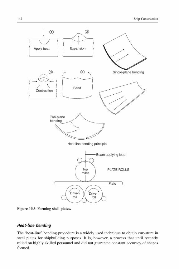
Heat-line bending
The ‘heat-line’ bending procedure is a widely used technique to obtain curvature insteel plates for shipbuilding purposes. It is, however, a process that until recentlyrelied on highly skilled personnel and did not guarantee constant accuracy of shapesformed.
Apply heat Expansion
BendContraction
Single-plane bending
Two-planebending
1 2
43
Heat line bending principle
Beam applying load
PLATE ROLLSToproller
Drivenroll
Drivenroll
Plate
Figure 13.3 Forming shell plates.
142 Ship Construction

Heat is applied in a line to the surface of a plate by a flame torch, with immediatecooling using air or water. The narrow heated line of material is prevented fromexpanding in the direction of the plate surface by the large mass of cold plate, andtherefore expands outwards perpendicular to the plate surface. On cooling, contrac-tion will take place in the direction of the plate surface, causing the plate to becomeconcave on the side to which heat was applied (see Figure 13.3). An experiencedoperator is able to make a pattern of such heat lines on a plate, producing controlleddistortion to obtain a required shape. Heat-line bending can be more time consumingthan using rolls or presses, but it has an advantage in that the plate holds its form moreaccurately when stiffening and other members are added later in the fabricationprocess. This is an important consideration since shape inaccuracy can be critical atthe erection stage in terms of lost production time. Heat-line bending may be usedafter cold forming to obtain improved accuracy. It is also used where a doublecurvature is required, for example on bulbous bow plates.
In recent years fully automated heat-line bending systems have been developedand installed in shipyards. These numerically controlled heat-line bending machinespermit highly accurate, reproducible thermal forming of any steel plate using the dataoriginating from the shipyard’s CAD system. More than double the productivity of thetraditional manual process is achieved.
Frame bending
The traditional system of bending side frames may still be in use for repair work, andis described as follows. A ‘set-bar’, which is a flat bar of soft iron, is bent to thescrieve line of the frame on the scrieve board and then taken to the frame bendingslabs. On these solid cast-iron slabs pierced with holes the line of the frame is marked,and modified to agree with the line of the toe of the frame. As the heated frame oncooling will tend to bend, the set-bar is sprung to allow for this change in curvaturebefore it is fixed down on the bending slabs by means of ‘dogs’ and pins inserted inthe slab holes. Whilst the set-bar is being fixed the frame section is heated in a longoil-fired furnace adjacent to the bending slabs. When at the right temperature it ispulled out onto the slabs and fixed with dogs and pins against the set-bar, as quickly aspossible. Tools are available for forcing the frame round against the set-bar, includinga portable hydraulic ram, and the toe of the web may require constant hammering toavoid buckling under compression.
As the frames fitted have their webs perpendicular to the ship’s center line, allexcept those immediately amidships will require beveling. A beveling machine isavailable that is placed in front of the furnace door, and as the frame is removed itpasses between its rollers, which are controlled so that the flange is bent at every pointto an angle indicated by a bevel board prepared by the mold loft.
Once bent, the bar is put aside to cool, but is fastened down to prevent its warpingin the vertical direction. When cold it is checked against the frame line drawn on theslabs. Meanwhile, the set-bar is turned over and used to bend the corresponding framefor the opposite side of the ship.
Plate and section preparation and machining 143

Cold frame bending
It is now almost universal practice to cold-bend ship frames using commerciallyavailable machines for this purpose. The frames are progressively bent by applicationof a horizontal ram whilst the frame is held by gripping levers (Figure 13.4). Any typeof rolled section can be bent in some machines with a limitation on the size of section.Obtaining the correct frame curvature can be achieved by the ‘inverse curve’ methodor numerical control. With the ‘inverse curve’ method the inverse curve informationcan be determined for each frame using a CAD/CAM system. The inverse curve ismarked onto the straight frame and the frame bent until the inverse curve becomesstraight on the curved frame (see Figure 13.4). A hydraulic cold-frame-bendingmachine can be controlled by numerical control tapes prepared in a similar manner tothe numerically controlled flame profilers, the frame line being initially defined fromthe computer-stored faired hull.
Section profilers
Plate profilers produce very accurate plate components for assembly into ship units andit is important that the supporting stiffeningmembers of the structure are producedwiththe same accuracy. Section profilers accurately cut, scallop, and bevel, as necessary, theprofile edge to be welded to the plate. Cutting is by oxy-fuel gas or plasma and inmodern systems is undertaken by a compact robot operating in a viewable enclosedworkstation with integral fume extraction. Prior to cutting, the stiffening member canbe moved through a marking cell where part identification and, where required,bending lines for inverse curve frame bending (see Figure 13.4) can be marked.
Robotics
Robots have in recent years been provided with improved control features that havemade them more adaptable to the workshop floor situation. For example, most robotsare now available with some form of ‘adaptive control’, which provides feedbackfrom the environment permitting, say, automatic adjustment of the robots path and/orits functions. Also, the provision of ‘off-line’ programming and simulation packagesmakes it possible to develop and test programs for the robot remotely. Thus, the robotcarries on working whilst new programs are produced for it.
Many of the world’s shipyards and shipyard systems suppliers have been devel-oping and implementing robots in shipbuilding. A large proportion of these devel-opments have been in fully automating the machine welding processes described inChapter 9, but other areas of adoption and trial have involved flame and plasma-arccutting, local shot-blasting and painting, and marking. Robots developed to date forshipyard usage are either associated with large gantry structures or are small portableunits. The former often have the movable robot mounted on the traveling gantry withsensors providing the adaptive control, and are employed for cutting and weldingprocesses. The latter can be manually transported or self-propelled, even climbingvertically, or for robotic transportation, and have been used for local welding indifficult situations and cleaning and painting.
144 Ship Construction

Chalk line
Inverse curve bending principle
Pin
Pin
DogDog Pin
Frame
Dog
Dog
Portable hydraulic
ram
Portable hydraulicramPin
DogSlabs
Frame
Pin
TRADITIONAL HEATED FRAME BENDING
Rotating vicingjaw
Motor driven feedwheels
Fixed
vicingjaw
Rotating vicingjaw
BILGE TURN BENDINITIAL POSITIONBOW FLARE BEND
COLD FRAME BENDING MACHINE (HYDRAULIC)
Figure 13.4 Frame bending.
Plate and section preparation and machining 145

Both the gantry-mounted and portable robotic units are commonly featured inautomated shipyard production units for panel, subassembly, and unit fabrication nowavailable to shipyards from specialist manufacturers.
Many of the early and existing robot programming systems are linked to theshipyard’s CAD system so that programs developed for the robot can be run ‘off line’with the three-dimensional graphics simulating the robot’s performance before it isput to work. A more recent patented development has seen the introduction ofa robotic welding unit controlled by an advanced machine vision-guided program-ming system. This is claimed to reduce preprogramming times to zero and no CADmodels are required.
Whilst robots have advantages in their use in difficult and unpleasant workconditions and tedious repetitive work situations, their development and adoption isincreasingly seen as a means to higher productivity and reduced manufacturing cost.
Further reading
Boekholdt R: Welding Mechanization and Automation in Shipbuilding Worldwide. AbingtonPublishing, 1996.
Kalogerakis: The use of robots in the shipbuilding industry, The Naval Architect, July/August1986.
New advances in efficient stiffener production from Dutch specialist, The Naval Architect,July 2004.
Shipbuilding technology, Feature in The Naval Architect, July/August 2003.Speeding throughput with automated plate and profile processing. Van der Giessen-de Noord:
creating innovative solutions, A supplement to The Naval Architect, September 2002.Vision-guided robots ‘open up new shipbuilding era’, The Naval Architect, February 2004.
Some useful websites
www.pemamek.com See welding, automation, and mechanization solutions for shipyards.www.tts-marine.com See production systems.http://www.intechopen.com/source/pdfs/279/InTech-Welding_robot_applications_in_
shipbuilding_industry_off_line_programming_virtual_reality_simulation_and_open_architecture.pdf
http://www.dtic.mil/cgi-bin/GetTRDoc?Location¼U2&doc¼GetTRDoc.pdf&AD¼ADA454642 Considers the economics of robots.
146 Ship Construction

14 Assembly of ship structure
Chapter OutlineAssembly 149Subassemblies 151Unit assembly 151Block assembly 152Outfit modules 152Unit erection 154Joining ship sections afloat 158Further reading 159Some useful websites 159
Historically, ships were constructed on a slipway piece by piece. The transition fromwood, to iron and then steel made little initial difference to the construction process,and the result was the typical shipyard layout as described in Chapter 11. Exceptionswere for military and large passenger ships.
During the Second World War a large number of merchant and war ships wererequired to be built in a short period of time. These requirements speeded the adoptionof welding in shipyards, and often led to the application of mass production tech-niques in shipbuilding. Prefabrication of ship units, i.e. the construction of individualsections of the ship’s structure prior to erection, became a highly developed science.Often, the units were manufactured at a location remote from the shipyard, anderection in the shipyards was carried out with schedules that still look very impressivetoday. Many of the more spectacular achievements in this field were obtained in theUSA, where much of the tonnage required during the war period was constructedusing these new advances. Unfortunately, the results of this crash building programwere not always entirely satisfactory; the reputation of welded structures, forexample, suffered for quite a time as a result of wholesale application withouta background of experience.
Also, the adoption of the prefabricated units was dictated by speed and large-scaleproduction, rather than economics. However, the potential benefits of units wereidentified and shipyards began to make the necessary investment, in additionalassembly workshops and larger cranes, to use prefabricated units. The initial low costof labor made traditional methods still reasonably economic. During the 1950s therewas an increase in ship size and the greater quantity of steel required for the structuresof these ships was a major driver for the adoption of units. Also, the costs of labor intraditional shipbuilding countries increased.
Ship Construction. DOI: 10.1016/B978-0-08-097239-8.00014-3
Copyright � 2012 Elsevier Ltd. All rights reserved.

From the mid 1950s, prefabrication was gradually being applied to merchant shipconstruction as shipyards benefitting from a high demand for ships were able to investin the additional workshops and cranes. Today, all vessels are to varying degreesprefabricated.
With riveted construction unit fabrication was rarely employed; the introduction ofwelding lent itself more favorably to this form of construction. With welding, simplerunit shapes (no staggered butts are required in the side shell, for example) and at firstless critical tolerances could be applied. In the early days of unit construction, theunits were assembled over size, so they could be trimmed to fit on the building berth(or dock). What is termed ‘green’ material was left on the unit edges, typically around20 mm. The unit was then lifted into place and cut to fit the structure, which hadalready been erected. The pressures of cost and required speed of construction haveled to much greater accuracy of assembly, so that for parallel body in particular, unitsand blocks can be produced with sufficient accuracy to allow them to be fitted andwelded without any adjustment. This provides a saving in man-hours and time.
Units may be constructed under cover, which is an attractive advantage, forexample, in Northern Europe and also in hot climates, not only because of workingconditions, but because of the better welding conditions. It is possible to turn units overto allow downhand welding, which is easier to perform and likely to provide betterresults. There is great advantage in keeping vertical and overhead welding toaminimum. Also, central services aremore readily available at the shop, with gases forcutting, air for chipping, and electric current for welding being placed where needed.Production planning techniques may be adopted with prefabrication sequences, thematerial and labor being planned in unit groups and the whole shipbuilding sequencebeing controlled to fit the time allowed on the berth, or in the building dock.
Once the unit construction method became established, and ships continued tobecome larger, the units were also made bigger and then several units were assembledinto large blocks. Figure 14.1 shows a typical side block for a single hull bulk carrier.When the first large tankers were built, typical units were around 50 tonnes. By 1970,lifting blocks of 500 tonnes were not uncommon. As the ships grew in size they alsogrew in complexity and outfitting began to be a bottleneck. In 1970, a 200,000-tonnedeadweight tanker could be constructed in two or three months in new or modernizedshipyards. It was then necessary to speed the outfitting of ships to avoid having severalships outfitting at the same time and to gain the advantages that faster constructionoffered in terms of increased income. The traditional approach of completing andlaunching the hull prior to outfitting in a basin or at a quay had to be modified.
Until unit and then block construction was established, the outfit and equipmentwere fitted at the berth and after launching at the fitting-out quay. Piping systems,ventilation, and the machinery units were fitted into the erected hull as independentitems. Likewise, the accommodation spaces were lined out and fitted with the furnitureand other fittings in situ. Whilst the production methods applied to the steelworkfabrication and erection were time saving and cost-effective, the haphazard and largelyuncontrolled methods of outfitting detracted from the overall production engineeringof the ship. Rather than plan outfit installation on a total ship system basis, it is todaystandard practice to plan this work for zone installation, the zone corresponding to
148 Ship Construction

a main compartment area that may be broken down into blocks or smaller assemblies.Pre-outfitting of each assembly or block may be of the order of 85–90%. Both steel-work and outfit are highly planned for each assembly and block unit, and fabricationand outfit installation are undertaken at a workstation where the facilities and materialare supplied to the workforce. Figure 14.2 shows a pipe module which could be fittedonto a steel block, or lifted directly into the ship during construction.
Assembly
Assembly is any process that takes a number of steel piece parts, or larger structures,and combines them into a larger structure. For very large ships, assembly consists ofa number of stages, putting together increasingly larger elements of the ship. Thenumber of stages varies between shipyards and especially varies with ship size. There
Wing tank/deck unit
Side shellpanelassembly
Hopper sideunit
Part transversebulkhead panel
Figure 14.1 Bulk carrier single shell side block unit.
Assembly of ship structure 149
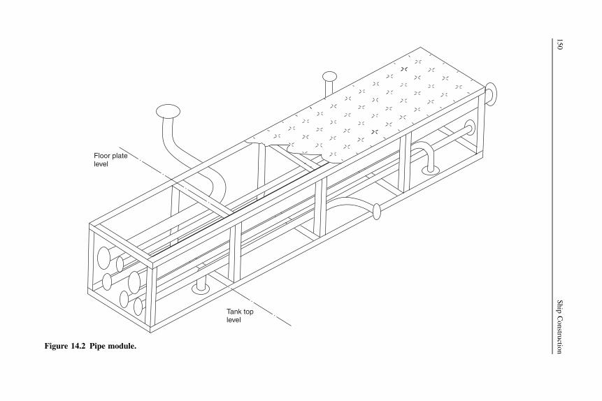
Floor platelevel
Tank toplevel
Figure 14.2 Pipe module.
150
Ship
Constru
ction

is not really a ‘typical’ ship, but as an illustration, considering a Panamax bulk carrierwith around 10,000 tonnes of steel, a length of around 250 meters and a breadth of 32meters, then the following assemblies can be described:
l Minor assembly: Brackets, intercostal floors or girders, bulwarks, two-dimensionalassemblies with five parts and a maximum size of 2 meters by 5 meters, weight below 2tonnes.
l Subassembly: A flat or curved panel, an egg box structure or other internal structure up toaround 12 meters by 12 meters, weight up to 20 tonnes.
l Unit assembly: A structure that can be erected in the building dock, typically one or twopanels and associated internal structure, weight up to 60 tonnes.
l Block: An assembly of two or more units into a bottom or side block, weighing up to 200tonnes.
The above are only illustrative and the dimensions and weights will vary for larger orsmaller ships.
Subassemblies
When plates and sections have been machined (cut, bent, beveled, etc.) they are readyfor assembly into two-dimensional ship units. Within the fabrication shop there areoften arranged a number of bays for different assemblies, for example flat plate panels,curved shell units, matrix or ‘egg box’ structures and some minor subassemblies. Allthese may be termed subassemblies if they are subsequently to be built into a largerthree-dimensional unit prior to erection. A two-dimensional plate panel assembly maybe highly automated (see also ‘Welding automation’ section in Chapter 10) withprepared plates being placed and tack welded prior to automatic welding of the butts,after which the plates are turned and back welded unless a single-sided weld processhas been used. The panel is marked and the stiffeners placed and welded automaticallyor with semi-automatic process. Marking and welding of two-dimensional panels isoften robotically controlled. Minor subassemblies such as deep frames consisting ofweb and welded face flat are also attached at this stage. Curved shell plates are placedon jigs and welded, and the various stiffening members can be aligned and welded ina similar manner to those on a flat panel assembly. Assembly jigs may also be used formatrix or ‘egg box’ assemblies, for example structures of solid and bracket plate floorswith longitudinal side girders that are to go into double-bottom units.
Unit assembly
In most instances the two-dimensional subassemblies will be built into three-dimensional unit assemblies. The size of the unit assembly will have been decided atan early stage of the planning process, ideally at the structural design stage.Constraints such as lifting capacities and dimensions that can be handled are takeninto consideration, as is the provision of breaks at natural features ensuring the blocksare self-supporting and easily accessed, etc. Panel assemblies used in the block may
Assembly of ship structure 151

well have dimensions restricted by the plate length that can be handled at themachining stage and this can subsequently influence block length. In the machineryarea the size and arrangements can be decided by zone outfit considerations.
Each unit should be designed for maximum downhand welding but may have to beturned for this purpose.
Block assembly
Several units can be combined into a block. Where a typical unit is a double-hullsection, a block can combine several of these to form a complete double-bottom blockover a plate length, or a side block. Units will have generally been outfitted duringassembly, for example the piping in a double-bottom unit, installed when the unit is inthe most convenient orientation and access is good. The block is sufficiently large,especially in zones such as machinery spaces or pump rooms, for substantial outfittingbefore transport to the building dock.
Units can be easily turned to effect outfit installation, particularly those containingmachinery flats in the aft engine room areas where pipework etc. can be fitted on theunderside of the flat in the inverted position and then it is turned to install equipmentabove the flat (see Figure 14.3). These already outfitted units can then be assembledinto a larger block and additional outfitting installed. Also, outfit modules can beinstalled into the blocks. A block’s center of gravity is calculated and lifting lugs soprovided that these operations can be undertaken, and finally the block can be sus-pended for erection at the building dock or berth and put into place in the correct plane.
Outfit modules
Units of machinery, pipework, and other outfit systems required for a specific zonecan be planned, built up into modules and installed as such into a block fabrication.Pipework in particular lends itself to this form of assembly and can, with carefulplanning at the CAD stage, be arranged in groupings so that pipe bank modules can bearranged for a particular zone. Figure 14.2 is an example of a pipe module. Modulescan range from a small pipe bank supported by light framing of pipe hangers, ora complete auxiliary machinery unit on its seating, which has even been test run priorto installation, to a large modular unit that, together with several similar units,constitutes the bulk of a complete engine room. The latter have been developed in oneEuropean shipyard, where macro-modules of the order of 10 m � 10 m � 4 m madeup of square rolled hollow sections (which function as pillars when installed) andhorizontal parts of the ship’s structure such as flats are completely outfitted. A numberof these macro-modules erected around the main engine are indistinguishable froma conventional engine room. Subcontractors are encouraged by the shipyards tosupply their equipment in module form.
Not all outfits can be incorporated into modules and a large number of piece partshave to be provided for fitting in any given zone at a particular time within the
152 Ship Construction

Figure 14.3 Assembly unit outfitted on both sides.
Assem
bly
ofship
structu
re153

assembly shops. To maintain production engineering standards, a concept of‘palletization’ has been developed whereby the piece parts for that zone are generatedat the CAD/CAM stage, bought in and/or fabricated, etc., and made available at theworkstation when the particular assembly is ready to receive them.
An ‘open top’ arrangement for blocks or smaller ships being outfitted under covercan facilitate installation of the items and modules.
Superstructure blocks are frequently fabricated separately and pre-outfitted withaccommodation before erection as a complete unit. Modular cabin units area common feature of modern shipbuilding, some companies specializing in theirproduction. Figure 14.4 shows a typical self-supporting cabin/toilet module completewith pipework, ventilation, electrical fittings and wiring, all of which can plug into theship’s systems, and all built-in furniture. An accommodation block must be specifi-cally designed for such modules and the sequence of module access and placement inthe block carefully planned.
Unit erection
When any panel and the block assemblies are complete there will be some time bufferbefore their erection at the building berth, building dock, or within the building hall to
Figure 14.4 Cabin/toilet module.
154 Ship Construction
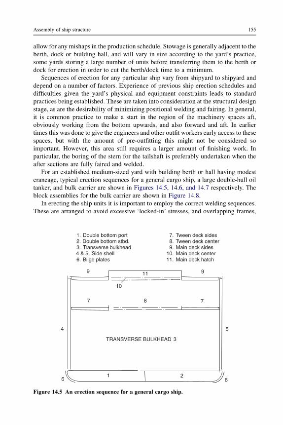
allow for any mishaps in the production schedule. Stowage is generally adjacent to theberth, dock or building hall, and will vary in size according to the yard’s practice,some yards storing a large number of units before transferring them to the berth ordock for erection in order to cut the berth/dock time to a minimum.
Sequences of erection for any particular ship vary from shipyard to shipyard anddepend on a number of factors. Experience of previous ship erection schedules anddifficulties given the yard’s physical and equipment constraints leads to standardpractices being established. These are taken into consideration at the structural designstage, as are the desirability of minimizing positional welding and fairing. In general,it is common practice to make a start in the region of the machinery spaces aft,obviously working from the bottom upwards, and also forward and aft. In earliertimes this was done to give the engineers and other outfit workers early access to thesespaces, but with the amount of pre-outfitting this might not be considered soimportant. However, this area still requires a larger amount of finishing work. Inparticular, the boring of the stern for the tailshaft is preferably undertaken when theafter sections are fully faired and welded.
For an established medium-sized yard with building berth or hall having modestcraneage, typical erection sequences for a general cargo ship, a large double-hull oiltanker, and bulk carrier are shown in Figures 14.5, 14.6, and 14.7 respectively. Theblock assemblies for the bulk carrier are shown in Figure 14.8.
In erecting the ship units it is important to employ the correct welding sequences.These are arranged to avoid excessive ‘locked-in’ stresses, and overlapping frames,
9 911
7 78
5
3
10
61 2
6
4
TRANSVERSE BULKHEAD
1. Double bottom port 7. Tween deck sides2. Double bottom stbd. 8. Tween deck center3. Transverse bulkhead 9. Main deck sides4 & 5. Side shell 10. Main deck center6. Bilge plates 11. Main deck hatch
Figure 14.5 An erection sequence for a general cargo ship.
Assembly of ship structure 155

223 3
5 5
6 678
4
4
8
1
1. Double-bottom center unit2. Double-bottom wing unit3. Bilge unit4. Longitudinal/transverse bulkhead unit
5. Double-hull side unit6. Deck/side unit7. Center deck unit8. Deck units
Figure 14.6 An erection sequence for a large double-hull tanker.
5
7
3 4
2
1
6
1. Double-bottom unit2. Lower bulkhead unit3. Upper bulkhead panel
4 & 5. Side block incorporating shell, tanks and part bulkhead
6. Deck between hatches7. Hatch coaming
Figure 14.7 An erection sequence for a dry cargo bulk carrier.
156 Ship Construction
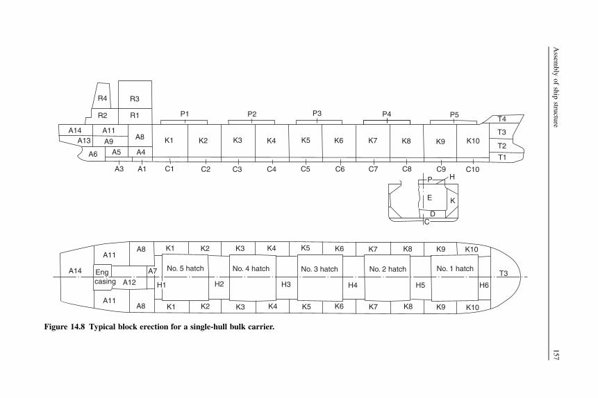
R4 R3
R2 R1
A14 A11A13 A9
A6 A5
A8
A4
A3 A1 C1
K1 K2
P1
C2 C3
K3
P2
C4
K4
C5
K5 K6
C6 C7
K7
C8
P
K8 K9
C9H
K10
C10
P5 T4
T3
T2
T1
P3 P4
KE
DC
A11
A14
A8 K1 K2
Engcasing A12
A7
H1
A11A8 K1 K2
No. 5 hatch
H2
K3 K4 K5 K6
No. 4 hatch No. 3 hatch No. 2 hatch No. 1 hatch
H3
K3 K4 K5
H4
K6 K7 K8 K9 K10
K7 K8 K9 K10
H5 H6
T3
Figure 14.8 Typical block erection for a single-hull bulk carrier.
Assem
bly
ofship
structu
re157

longitudinals, stiffeners, etc. may be left unwelded across unit seams and butts untilthese are completed in a similar manner to that described in Chapter 10.
In erecting units tolerances are a problem, more so on three-dimensional units thanwith two-dimensional units, and particularly at the shaped ends of the ship where‘green’ material is still often left. Quality control procedures in the manufacturingshops to ensure correct dimensioning and alignment are very necessary if time-consuming, expensive, and arduous work at the berth is to be avoided. Improvementsin this area have been made with the use of accurate jigs for curved shell units,planned weld sequences, and the use of lower heat input welding equipment,dimensional checks on piece parts, and the use of laser alignment tools for setting updata and checking interfaces.
More recently, the use of digital photogrammetry has been adopted in someshipyards. Photographs of a unit, or of an assembly at an earlier production stage, aretaken from several locations and software then converts the image data into anaccurate, three-dimensional view of the unit. This is useful in the alignment of unitsand in ensuring successive units are assembled to fit those already in place.
Tolerance allowance data is built up with experience and can become very accuratewhen building standard ships.
A number of large shipbuilding firms building the super tankers, large chemicalcarriers, bulk carriers, etc. may assemble much larger ‘mega-blocks’ that can be thefull width of the ship. These are transported to the building berth or a building dock,lifted into place and joined. Rather than erecting 100–150 units at the berth or dock,they may only have to place and join as few as 10–15.
Joining ship sections afloat
Owing to the enormous increase in size of bulk carriers and tankers, some shipyardswith restricted facilities, building berth or dock size in particular, have resorted in thepast to building the ship in two halves and joining these afloat. This is not a veryefficient process and is adopted as an expedient only.
Where the two sections are to be joined afloat, extremely accurate fit-up of thesections is aided by the possibility of ballasting the two ship halves. The twosections may then be pulled together by tackles, and for the finer adjustmentshydraulic cylinders may be used, extremely accurate optical instruments beingemployed to mark off the sections for alignment. One method adopted is that wherea cofferdam is arranged in way of the joint, a caisson is brought up against the ship’shull, and the cofferdam and caisson are pumped dry. To balance any tendency forthe vessel to hog during the pumping of the cofferdam, it is necessary to shift ballastin the fore and aft sections. Once the spaces are dried out, welding of the completejoint may be undertaken, the resulting weld being X-rayed to test the soundness ofsuch a critical joint. On completion of the paint scheme in way of the joint thecaisson is removed.
A similar method makes use of a rubber ‘U’ form ring rather than a caisson, whichneeds modification for each ship size.
158 Ship Construction

If a dry dock is available the sections may be aligned afloat and even welded abovethe waterline, the rest of the joint or the complete joint being secured by strongbacks.The welding of the rest or the whole joint is carried out in the dock.
Further reading
Boekholt R: Welding Mechanization and Automation in Shipbuilding Worldwide. AbingtonPublishing, 1996.
Samsung’s mega-block revolution. Surveyor, Fall 2005 edition. American Bureau of Shippingpublication.
Some useful websites
http://www.stxons.com/service/eng/main.aspx The site includes a ‘virtual tour’ of theshipyard.
http://www.meyerwerft.de/ Useful pictures and descriptions of the shipyard.
Assembly of ship structure 159
15 Launching
Chapter OutlineEnd launches 162
Building slipway 162Launching ways and cradle 164Lubricant 165Releasing arrangements 165Launching sequence 168Arresting arrangements 168
Side launches 170Building docks 170Ship lifts 171Floating docks 171Marine railways 172Further reading 172Some useful websites 172
This chapter identifies the various means of transferring a ship from the land on whichit is constructed to the water. The traditional end launching process is described as thisis the most complex method. End launching is now less common as most newershipyards have a building dock. Other methods are less common and include sidelaunching, a ship lift, a floating dock, or a pontoon.
Whilst many modern shipyards now construct ships in building docks and floatthem out and some utilize ship lifts, a good number of long-established shipyards arestill launching ships in the traditional manner. A significant advance has beenprovided by computer programs that allow prior assessment of the performance of theship and the loading it may experience during the launch, both on the ways and in thewater.
Launching involves the transference of the weight of the ship from the keel blocks,shores, etc. on which it was supported during construction, to a cradle on which it isallowed to slide into the water. Normally the vessel is launched end on, stern first, buta number of shipyards located on rivers or other narrow channels are obliged tolaunch the vessel sideways. Vessels have been launched bow first, but this was a rareoccurrence as the buoyancy and weight moments, as well as the braking force, aregenerally more favorable when the vessel is launched stern first. There is also a dangerof damage to propellers and rudders as the ship leaves the end of the slipway.
Ship Construction. DOI: 10.1016/B978-0-08-097239-8.00015-5
Copyright � 2012 Elsevier Ltd. All rights reserved.

End launches
On release of a holding mechanism the launching cradle with the ship slides down theground ways under the action of gravity. When the stern has entered the water thevessel is partly supported by buoyancy and partly by the ground ways. If thisbuoyancy is inadequate after the center of gravity of the ship has passed the way ends,the ship may tip about the way ends, causing large pressures on the bottom shell andon the ends of the ground ways. To avoid this the greatest depth of water over the wayends should be utilized, and the ground ways extended into the water if necessary.Where this proves impossible it becomes necessary to strengthen the way ends andprovide shoring in the bottom shell region, which is likely to be damaged. Theseremedies are often expensive.
As the vessel travels further into the water the buoyancy becomes sufficient to liftthe stern. The vessel then pivots about the forward poppets, i.e. the fore end of thelaunching cradle. These are designed to take the load thrown on them by the pivotingaction, the load being widely distributed in order not to squeeze out the lubricantbetween the sliding surfaces. Shoring may also be found necessary forward in the shipto prevent structural damage at the time the stern lifts.
Building slipway
Conventional slipways or berths are relatively solid and reinforced with piles toallow them to sustain the weights of ships built upon them. During building the keelblocks take the greater part of the weight, the remainder being carried by shores and,where used, bilge blocks. Foundations under the probable positions of ground waysshould also be substantial, since during a launch the ways are subject to largepressures.
Keel blocks are arranged so that the height of keel above the ground is 1.25–1.5 m, giving reasonable access, but not too high so that a large amount ofpacking is required (see Figure 15.1). At the bow the height of the keel must besufficient to allow the ship’s forefoot to dip the required amount without strikingthe ground during pivoting when the stern lifts at launch. To suit the declivity ofthe launching ways determined beforehand, the keel is also inclined to thehorizontal at about 1 in 20, or more where the shipyard berths have a largerslope.
To transfer the ship from the building blocks to the launching cradle, thecommonest practice is to drive wedges into the launching cradle. This lifts theship and permits the removal of the keel and bilge blocks together withthe shores. In large ships it becomes necessary to split the blocks to remove them,but several types of collapsible blocks have been used to overcome this difficulty.One type is the sand box, which contains sand to a depth of 80–100 mm held ina steel frame located between two of the wooden blocks. This steel frame may beremoved and the sand allowed to run out. Another type is a wooden block sawndiagonally, the two halves being bolted so that they collapse on removal ofthe bolts.
162 Ship Construction

REINFORCED BERTH
Bilgeblocks
ShoreSpace
for launchingways
Keelblocks Shore
Concrete
Spacefor launching
ways
Bilgeblocks
Figure 15.1 Building blocks.
Launching
163

Launching ways and cradle
The fixed ground ways or standing ways on which the cradle and ship slide may bestraight or have a fore and aft camber. Transversely the ground ways are normally laidstraight but can be canted inwards to suit the ship’s rise of floor. Usually, the groundways have a small uniform fore and aft camber, say 1 in 400, the ways being the arc ofa circle of large radius. This means that the lower part of the ways has a greater declivity(say 1 in 16) than the upper part of the ways (say 1 in 25). As a result a greater buoyancyfor the same travel of the ship beyond the way ends is obtained, which will reduce theway end pressures. Additional advantages are increased water resistance slowing thevessel and a bow height that is not excessive. The slope of ground ways must beadequate to allow the vessel to start sliding and, if too steep, a large amount of shoringwill be required to support the bow; also, the loads on the releasing arrangements willbe high. Straight sliding ways have declivities of the order of 1 in 25 to 1 in 16.
Generally two ground ways are fitted, the distance between the ways being aboutone-third the beam of the ship. It is often desirable that the cradle should be fitted inway of longitudinal structural members and the ground ways over slipway piling,these considerations deciding the exact spacing. Some large ships have been launchedon as many as four ways, and in Germany and the Netherlands it is common practiceto launch vessels on a single center-line ground way. The width of the ways should besuch that the launching weight of the ship does not produce pressures exceeding about20 tonnes per square meter.
Ground ways are laid on supporting blocks and extend down to the low water markso that they are covered by at least 1 meter of water at high tide. To guide the slidingways as they move over the ground ways, a ribband may be fitted to the outer edge ofthe ground ways. This could be fitted to the inner edge of the sliding ways, but whenfitted to the ground ways has the advantage that it aids retention of the lubricatinggrease. Finally, the ground ways are shored transversely to prevent sideways move-ment and longitudinally to prevent them from moving down with the ship.
The sliding ways, covering about 80% of the length of the vessel, form the lowerpart of the cradle, the upper part consisting of packing, wedges, and baulks of timberwith some packing fitted neatly to the line of the hull in way of the framing. In veryfine-lined vessels the forward end of the cradle, referred to as the forward poppet, willneed to be relatively high, and may be built up of vertical timber props tied togetherby stringers or ribbands. This forward poppet will experience a maximum load thatmay be as much as 20–25% of the ship’s weight when the stern lifts. It is thereforedesigned to carry a load of this magnitude, but there is a danger in the fine-lined vesselof the forward poppets being forced outwards by the downward force, i.e. the bowmight break through the poppets. To prevent this, cross ties or spreaders may bepassed below the forefoot of the vessel and brackets may be temporarily fastened tothe shell plating at the heads of the poppets. In addition, saddle plates taken under theforefoot of the ship with packing between them and the shell may be fitted to transmitthe load to the fore poppets and hence ground ways.
In many modern ships the bow sections are relatively full and little support isrequired above the fore end of the sliding ways. Here short plate brackets may be
164 Ship Construction

temporarily welded between the shell plating and heavy plate wedge rider, as illus-trated in Figure 15.2. The design of the forward poppets is based on greater pressuresthan the lubricant between the sliding ways and ground ways could withstand ifapplied for any length of time. However, as the duration of pivoting is small, and thevessel has sufficient momentum to prevent sticking at this stage, these high pressuresare permissible.
At the after end of the cradle considerable packing may also be required, and againvertical timber props or plate brackets may be fitted to form the after poppet.
Lubricant
For the ship to start sliding on release of the holding arrangements, it is necessary forthe ship to overcome the coefficient of friction of the launching lubricant. To do thisthe slope of the ways under the vessel’s center of gravity must exceed the lubricant’scoefficient of friction. An estimate of the frictional resistance of the grease must bemade before building the ship, since the declivity of the keel is dependent to a largeextent on the slope of the ways.
Formerly, melted tallow was applied to the ways, allowed to harden, and thencovered with a coat of soft soap. Since the mid 1900s patent mineral-based greaseshave been applied to the ground ways, these greases being virtually unaffected bytemperature changes and insoluble in water whilst adhering firmly to the ways.A commercially marketed petroleum-based launching grease is applied over themineral grease base coat. This has a coefficient of friction that is low enough to allowinitial starting and the maintenance of sliding until the initial resistance of the basecoat is overcome by frictional heat. To prevent the petroleum-based grease fromsoaking into the sliding ways, a base coat may be applied to them. Standing ways thatextend into the water may be dried out at low tide prior to the launch and the base coatand grease applied.
Releasing arrangements
Small ships may be released by knocking away a diagonal dog-shore (see Figure 15.3)fitted between the sliding and standing ways.
In most cases, however, triggers are used to release the ship. There are severaltypes available, hydraulic, mechanical, and electrical-mechanical triggers havingbeen used. Electrical-mechanical triggers are commonly used for rapid simultaneousrelease in modern practice. The hydraulic trigger is less easily installed and less safe.The electrical-mechanical trigger illustrated in Figure 15.3 is generally located nearamidships and a small pit is provided in the berth to accommodate the falling levers.A number of triggers will be fitted depending on the size of the vessel to be launched;in the case of the 75,000-tonne bulk carrier for which a launching sequence is givenbelow, six triggers were fitted for the launch.
These triggers are in effect a simple system of levers that allow the large loadsacting down the ways to be balanced by a small load on the releasing gear. Theprinciple is often compared with that of a simple mechanical reduction gearing.
Launching 165
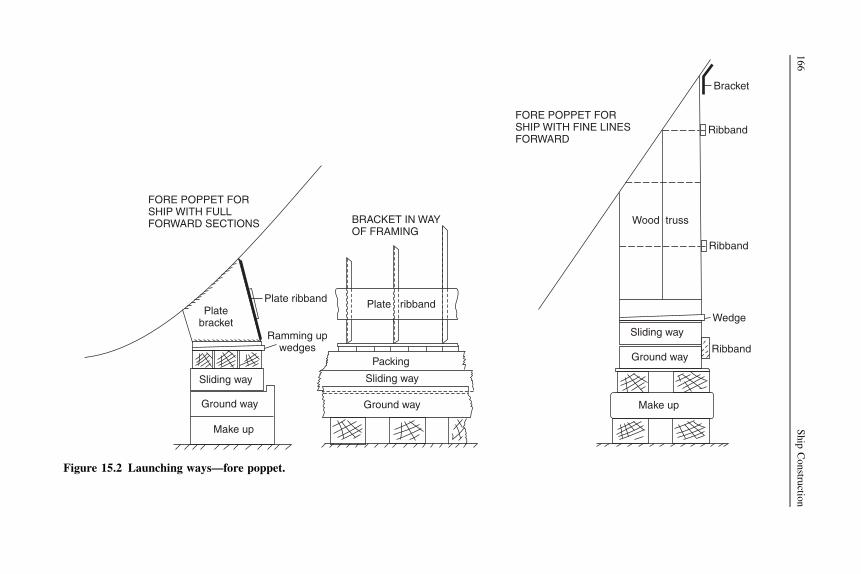
FORE POPPET FORSHIP WITH FULLFORWARD SECTIONS
Platebracket
Plate ribband
Ramming upwedges
Make up
Ground way
Sliding way
BRACKET IN WAYOF FRAMING
Plate ribband
Packing
Sliding way
Ground way Make up
Ground way
Sliding way
Ribband
Wedge
Ribband
Ribband
Wood truss
Bracket
FORE POPPET FORSHIP WITH FINE LINESFORWARD
Figure 15.2 Launching ways—fore poppet.
166
Ship
Constru
ction

BeamDog shore
Dog shore
PLAN
On sliding wayOn standing way
Groundshore
Steel shod
Beam
Sliding way
ELEVATION
Steel shod
MECHANICAL LAUNCH TRIGGER (ELEVATION)
Sliding way
Ground way
2nd lever
Solenoid release unit
Slip shackle
1stlever
3rd lever
Load
Anvil
Figure 15.3 Release arrangements for ship launch.
Launching
167
Simultaneous release of the triggers is achieved by means of catches held by sole-noids wired in a common circuit. These are released immediately the circuit current isreversed.
Launching sequence
As a guide to the procedure leading up to the launch, the following example is givenfor the launch of a 75,000-tonne bulk carrier. The launch ways have been built up asthe ship is erected from aft; the ways have been greased and the cradle erected.
1. Four days before launch a start is made on ramming up the launch blocks, i.e. driving in thewedges (Figure 15.2) to raise ship off the building blocks. This is done by a dozen or so menusing a long ramming pole, a gang working either side of the ship.
2. Two days before the launch a start is made on removing the shores.3. On the morning of the launch everything is removed up to the high water mark and tumbler
shores are put in aft. These are inclined shores that fall away as the ship starts to move.4. Every second keel block is then removed and the vessel is allowed to settle.5. An evenly distributed number of keel blocks are then taken out so that only about 20 keel
blocks are left supporting the ship.6. Half an hour before the launch the last remaining keel blocks are removed.7. The bilge blocks are then removed.8. The full ship’s weight comes on the triggers at the time planned for the launch.9. Release of triggers on launch by sponsor.
If the vessel fails to start under the action of gravity, the initial movement may beaided by hydraulic starting rams, which are provided at the head of the cradle.
Arresting arrangements
In many cases the extent of the water into which the ship is launched is restricted. It isthen necessary to provide means of arresting the motion of the ship once it is in thewater. There are a number of methods available for doing this, one or more beingemployed at most ship launches.
The commonest arrangement is to use chain drags, which are generally arrangedsymmetrically on either side of the ship. Each chain drag is laid in the form ofa horseshoe with its rounded portion away from the water, so that as the ship movesdown the ways the forward portion of the drag is pulled through the remainder of thepile. This prevents any excessive shock load in the chain, which would occur if thepile of chain were to be suddenly accelerated to the speed of the ship. The wire ropedrag lines are attached to temporary pads on the side of the ship, and supported byrope tricing lines as they are led slightly forward and then aft along the ship’s sides.Each drag line is then led forward and shackled to the chain drag (see Figure 15.4). Asthe ship is released and moves aft the tricing lines are broken in turn, the work doneabsorbing some of the ship’s energy.
To further increase the resistance to motion of the ship, wooden masks may befitted at the stern of the ship. The mask is made as large as possible but located lowdown to present a flat surface to the water in the direction of motion. Masks are often
168 Ship Construction

Welded padsTricing lines
Wire linesCradle
ELEVATION
MASKS SECTION AFTLOOKING FOR’D
Mask ofwooden slats
Way end
PLAN
Chain drags
SLEWING ARRANGEMENTS
Wire
Figure 15.4 Arresting arrangements at launch.
Launching
169

constructed of horizontal pieces of wood with spaces left between each piece toincrease the resistance.
One or two shipyards are forced to provide arrangements for slewing the vesselonce it has left the ways, as the river into which the ships are launched is very narrowin relation to the ship’s length. Chain drags, weights, or anchors may be placed in thewater to one side of the building berth for this purpose. These are then made fast to thestern of the ship with drag lines of a predetermined length. Once the vessel is clear ofthe ways the slack of the lines is taken up and the stern swings so that the ship ispointing up river.
Side launches
Side launching is often used where the width of water available is considerablyrestricted. There are in fact some advantages to this method, for example the absenceof keel declivity, and the relatively simple cradle and short ground ways that do notextend into the water. However, it means that a large area of waterfront is taken up bya single building berth, and the ship is only reasonably accessible from one sideduring construction. Side launching is usually restricted to small ships, typically nomore that around 100 meters in length.
The ground ways are arranged transversely, i.e. at right angles to the line of keel.Sliding ways can also be placed transversely with the packing above them forming thecradle, but they are generally arranged longitudinally. In this case where they areparallel to the keel, the sliding ways are in groups covering two or three ground ways.Packing again forms the cradle with tie pieces between the groups of sliding ways.
One of the features of side launching is the drop where the ground ways are notextended into the water; consequently, large angles of heel occur when the vesselstrikes the water. As a result it is necessary to carry out careful stability calculationsand close any openings before side launching a vessel. It is true, of course, thatstability calculations are also required for a conventional end launch.
Building docks
Perhaps the greatest advantage of the building dock is the relative simplicity of thetask of getting the vessel waterborne (see Chapter 11). When it is convenient the dockmay be flooded and the vessel floated out. In a building dock it is also possible toconstruct two ships at the same time. The second of two is usually at the landward endof the dock, and can be separated from the seaward end by an intermediate dock gate.The first ship can then be floated out of the dock while the second remains in the dry.Once the dock is dewatered the second ship can be moved to the seaward end anda third ship started. This allows better utilization of the large and expensive cranes,and also allows double the time to complete the more outfit-intensive zones of theship, usually the aft machinery spaces and accommodation.
170 Ship Construction

The dock also has a horizontal base, which simplifies alignment of structural unitsor blocks and management of the ship dimensions.
Calculations are needed to check the stability and loads exerted by the blocksduring flooding, the whole problem being similar to that of undocking a vessel thathas been dry-docked for survey or other reasons.
In some shipyards conventional berths are fitted at the river or sea end with what isvirtually a pair of dock gates. This can be of advantage when working the aft end ofthe ship and installing the ways. In many instances it also permits higher tides over theway ends when the gates are opened for a launch. A dock gate is ideal in tidelessconditions, for example in the Baltic or Mediterranean Seas. The ship can be builtwith the gate closed, maintaining a dry working environment. When the gate isopened the lower part of the slipway floods and provides sufficient water depth for thelaunch to be carried out successfully.
Ship lifts
Whilst large ships may be extruded out of building halls on to a slipway (Chapter11) and large sections transferred by similar means to the head of the slipway andraised onto it for joining and launching, smaller complete ships may be transferredto a ship lift for launching. Rail systems are incorporated into the building hall andlead out to the open ship lift. The best known of these ship lift systems is thepatented ‘Syncrolift’, originally used for slipping ships for repairs and surveys butnow also used by some shipyards for launching new ships. Ship lifts basicallyconsist of a series of transverse beams, each supported by wires or chains suspendedfrom a winch on each side. The beams have the transfer rails running longitudinallyacross them. A platform is also supported by the beams to provide access when theship is lifted clear of the water. To launch, the ship is positioned on the structure,which can be lowered into the water and the ship floated off the platform. The liftcan also be used to recover a ship from the water for repair. The platform is raisedand lowered mechanically or hydraulically and is usually provided with transferarrangements so that the vessel can be moved on or off the platform either laterallyor in line with the platform.
Originally, ship lifts were used for fleets of small ships, for example in fishingports, but have increased in size for large commercial repairs and some construction.The largest lift is able to lift over 20,000 tonnes.
Floating docks
Occasionally, and usually as a temporary expedient, a ship can be built on the land andtransferred to a floating dock for launching. The arrangement is similar to a ship lift,with rails to allow the completed ship to be transferred onto the dock. The dock is thensunk in the location or may be towed to deeper water so the ship can be floated off.
Launching 171

As an alternative a ship may be transferred to a pontoon, in an operation similar toan offshore structure loadout. The pontoon will require some reserve buoyancy tomaintain stability during the operation and this is usually provided by ‘towers’ at eachcorner. Such a specialized pontoon is less expensive than a conventional floatingdock.
Marine railways
A few small shipyards use a slipway with a set or rails that extend into the water. Theship is constructed on, or transferred to, a cradle that can run on the rails. For launch,the cradle is lowered down the slipway until the ship floats off. The operation is undercontrol, unlike a dynamic end launch where, once started, the ship cannot be stopped.As with the ship lift, a marine railway can also be used to recover ships for repair.
Further reading
Dunn, Kennedy, and Tibbs, Launching in the 21st century. The Royal Institution of NavalArchitects, Drydocks, Launching and Shiplift Conference, 2003.
Pattison, Dixon, and Hodder, Launching and docking: Experiences at VT shipbuilding. TheRoyal Institution of Naval Architects, Drydocks, Launching and Shiplift Conference,2003.
Salisbury and Dobb, Recent dynamic launches at Barrow in Furness: Prediction and reality.The Royal Institution of Naval Architects, Drydocks, Launching and Shiplift Conference,2003.
The vertical shiplift’s role in modern shipyards, The Naval Architect, February 1995.
Some useful websites
http://www.royalhaskoning.co.uk The company is a designer of dry docks worldwide.http://www.fsg-ship.de/ The Flensberg shipyard site, includes webcams and video.
172 Ship Construction

16 Bottom structure
Chapter OutlineKeels 175Single-bottom structure 177Double-bottom structure 177
Inner bottom plating 180Floors 180Transversely framed double bottom 180Longitudinally framed double bottom 183Additional stiffening in the pounding region 183Bottom structure of bulk carriers 184Testing double-bottom compartments 184
Machinery seats 184
Originally, ships were constructed with single bottoms, liquid fuels and fresh waterbeing contained within separately constructed tanks. The double-bottom structure,which provides increased safety in the event of bottom shell damage, and alsoprovides liquid tank space low down in the ship, evolved during the early part of thetwentieth century. Today, only small vessels such as tugs, ferries, and cargo ships ofless than 500 gross tonnage have a single-bottom construction. Larger ocean-goingvessels are fitted with some form of double bottom.
Keels
At the center line of the bottom structure is located the keel, which is often said toform the backbone of the ship. This contributes substantially to the longitudinalstrength and effectively distributes local loading caused when docking the ship. Thecommonest form of keel is that known as the ‘flat plate’ keel, and this is fitted in themajority of ocean-going and other vessels (see Figure 16.1a). A form of keel found onsmaller vessels is the bar keel (Figure 16.1b). The bar keel may be fitted in trawlers,tugs, etc. and is also found in smaller ferries.
Where grounding is possible this type of keel is suitable with its massive scantlings,but there is always a problem of the increased draft with no additional cargo capacity. Ifa double bottom is fitted the keel is almost inevitably of the flat plate type, and bar keelsare more often associated with open floors, but a flat plate keel can be fitted in way ofopen floors.
Ship Construction. DOI: 10.1016/B978-0-08-097239-8.00016-7
Copyright � 2012 Elsevier Ltd. All rights reserved.

Ships
Middle strake of tank top
(a) FLAT PLATE KEEL
Flat keelplate
Continuouscenter girder
(b) BAR KEEL
Garboard strakeof bottom shell
Bar keel
Drain hole
Solid floor
Flange
Ships
(c) DUCT KEEL
Solidfloor
Ships
Stiffener
Side girder Piping
Stiffener
Solidfloor
Figure 16.1 Keels.
176
Ship
Constru
ction

Duct keels (Figure 16.1c) are provided in the double bottoms of some vessels. Theserun from the forward engine room bulkhead to the collision bulkhead and are utilized tocarry the double-bottom piping. The piping is then accessible when cargo is loaded, anentrance to the duct being provided at the forward end of the engine room. No duct isrequired aft of the engine room as the piping may be carried in the shaft tunnel. Awidthof not more than 2.0 m is allowed for the duct, and strengthening is provided at the tanktop and keel plate to maintain continuity of strength of the transverse floors.
Single-bottom structure
In smaller ships having single bottoms the vertical plate open floors are fitted at everyframe space and are stiffened at their upper edge. A center-line girder is fitted and oneside girder is fitted each side of the center line where the beam is less than 10 m.Where the beam is between 10 and 17 m, two side girders are fitted and if any bottomshell panel has a width-to-length ratio greater than 4 additional continuous or inter-costal stiffeners are fitted. The continuous center and intercostal side girders arestiffened at their upper edge and extend as far forward and aft as possible.
The single-bottom structure is shown in Figure 16.2 and for clarity a three-dimensional representation of the structure is also provided to illustrate thosemembers that are continuous or intercostal. Both single and double bottoms havecontinuous and intercostal material, and there is often some confusion in the student’smind as to what is implied by these terms.
Awood ceiling may be fitted across the top of the floors if cargoes are to be carried,but this does not constitute an inner bottom offering any protection if the outer bottomshell is damaged.
Double-bottom structure
An inner bottom (or tank top) may be provided at a minimum height above the bottomshell, and maintained watertight to the bilges. This provides a considerable margin ofsafety, since in the event of bottom shell damage only the double-bottom space maybe flooded. The space is not wasted but utilized to carry oil fuel and fresh waterrequired for the ship, as well as providing ballast capacity.
The minimum depth of the double bottom in a ship will depend on the classificationsociety’s requirement for the depth of center girder. It may be deeper to give therequired capacities of oil fuel, fresh water, and water ballast to be carried in the bottom.Water-ballast bottom tanks are commonly provided right forward and aft for trimmingpurposes and if necessary the depth of the double bottom may be increased in theseregions. In way of the machinery spaces the double-bottom depth is also increased toprovide appreciable capacities of lubricating oil and fuel oil. The increase in height ofthe inner bottom is always by a gradual taper in the longitudinal direction, no suddendiscontinuities in the structure being tolerated.
Bottom structure 177

ELEVATION
Intercostal side girder
Flange
Floor
Flange Intercostal side girder
LOOKING FOR’D
Solid floor
Centergirder
Barkeel
Ships
Manhole
OPEN FLOORS
Flange
Fore and aftintercostalside keelsons
Centergirder
Transverseplate floors
Garboard strakeBar keel
Figure 16.2 Single-bottom construction.
178
Ship
Constru
ction

Double bottoms may be framed longitudinally or transversely (see Figure 16.3),but where the ship’s length exceeds 120 m it is considered desirable to adoptlongitudinal framing. The explanation for this is that on longer ships tests andexperience have shown that there is a tendency for the inner bottom and bottom shellto buckle if welded transverse framing is adopted. This buckling occurs as a result ofthe longitudinal bending of the hull, and may be avoided by having the platinglongitudinally stiffened.
(a) TRANSVERSEL Y FRAMED DOUBLE BO TT OM
Margin plate
Brac k et floors
Solid floor
T ank top
Intercostal side girder
Continuous center girder
Flat plate k eel
(b) LONGITUDINALL Y FRAMED DOUBLE BO TT OM
Brac ke t floors
Solid floor
Continuous center girder
Flat plate k eel
Bottom longitudinal s
Intercostal side girder
Inner bottom longitudinals
T ank top Solid floor
Figure 16.3 Double-bottom construction.
Bottom structure 179

Double bottoms in the way of machinery spaces that are adjacent to the after peakare required to be transversely framed.
Inner bottom plating
The inner bottom plating may, in a general cargo ship, be sloped at the side to forma bilge for drainage purposes. It is not uncommon, however, for it to be extended tothe ship’s side, and individual bilge wells are then provided for drainage purposes (seeChapter 26). In vessels requiring a passenger certificate it is a statutory requirementfor the tank top to extend to the ship’s side. This provides a greater degree of safety,since there is a substantial area of bilge that may be damaged without flooding spacesabove the inner bottom.
At the center line of the ship the middle strake of the inner bottom may beconsidered as the upper flange of the center-line docking girder, formed by the centergirder and keel plate. It may therefore be heavier than the other strakes of innerbottom plating. Normally, a wood ceiling is provided under a hatchway in a generalcargo ship, but the inner bottom plating thickness can be increased and the ceilingomitted. If grabs are used for discharging from general cargo ships the plate thicknessis further increased, or a double ceiling is fitted.
Floors
Vertical transverse plate floors are provided both where the bottom is transversely andlongitudinally framed. At the ends of bottom tank spaces and under the main bulk-heads, watertight or oiltight plate floors are provided. These are made watertight oroiltight by closing any holes in the plate floor and welding collars around anymembers that pass through the floors. Elsewhere, ‘solid plate floors’ are fitted tostrengthen the bottom transversely and support the inner bottom. These run trans-versely from the continuous center girder to the bilge, and manholes provided foraccess through the tanks and lightening holes are cut in each solid plate floor. Also,small air and drain holes may be drilled at the top and bottom respectively of the solidplate floors in the tank spaces. The spacing of the solid plate floors varies according tothe loads supported and local stresses experienced. At intermediate frame spacesbetween the solid plate floors, ‘bracket floors’ are fitted. The bracket floor consistssimply of short transverse plate brackets fitted in way of the center girder and tanksides (see Figures 16.4 and 16.5).
Transversely framed double bottom
If the double bottom is transversely framed, then transverse solid plate floors, andbracket floors with transverse frames, provide the principal support for the inner bottomand bottom shell plating (Figure 16.4). Solid plate floors are fitted at every frame spacein the engine room and in the pounding region (see the end of this chapter). Also, theyare introduced in way of boiler seats, transverse bulkheads, toes of brackets supportingstiffeners on deep tank bulkheads, and in way of any change in depth of the double
180 Ship Construction

SOLID FLOORShip’s
Continuouscenter girder
Margin plate
Lighteninghole
Tank top
Flat barstiffener
Drain holes
ManholeIntercostalside girder Air holes
Margin plate
Bracket
BRACKET FLOOR
Bracket
Continuouscenter girderIntercostal
side girder
Bottom frame
Flatstiffenner
Inner bottom frame
AnglestrutFrame
Tank top (inner bottom)
Figure 16.4 Transversely framed double-bottom construction.
Botto
mstru
cture
181

Margin plate
Lighteninghole
Tank top Continuous center girder Ship’sInner bottom longitudinals
Air holes
Drain holes
Intercostalside girder Manhole
Bottom longitudinals SOLID FLOOR
Margin plate
Bracket
Flange Flange
Bracket
BRACKET FLOOR
Flat barstiffener
Intercostalside girder
Angle strut
Tank top (inner bottom)
Bottom longitudinals
Inner bottom longitudinals
Figure 16.5 Longitudinally framed double-bottom construction.
182
Ship
Constru
ction

bottom. Where a ship is regularly discharged by grabs, solid plate floors are also fittedat each frame. Elsewhere, the solid plate floors may be spaced up to 3.0 m apart, withbracket floors at frame spaces between the solid floors. The plate brackets of bracketfloors are flanged and their breadth is at least 75% of the depth of the center girder at thebracket floors. To reduce the span of the frames, which should not exceed 2.5 meters, atthe bracket floor, vertical angle or channel bar struts may be fitted. Vertical stiffeners,usually in the form of welded flats, will be attached to the solid plate floors, which arefurther strengthened if they form a watertight or oiltight tank boundary.
One intercostal side girder is provided port and starboard where the ship’s breadthexceeds 10 m but does not exceed 20 m, and two are fitted port and starboard wherethe ship’s breadth is greater. In way of the bracket floors a vertical welded flat stiffeneris attached to the side girder. Additional side girders are provided in the engine room,and also in the pounding region.
Longitudinally framed double bottom
In a longitudinally framed double bottom, solid plate floors are fitted at every framespace under the main engines, and at alternate frames outboard of the engine seating.They are also fitted under boiler seats, transverse bulkheads, and the toes of stiffenerbrackets on deep tank bulkheads. Elsewhere, the spacing of solid plate floors does notexceed 3.8 m, except in the pounding region, where they are on alternate framespaces. At intermediate frame spaces brackets are fitted at the tank side and at thecenter girder, where they may be up to 1.25 m apart. Each bracket is flanged and willextend to the first longitudinal (Figure 16.5).
One intercostal side girder is fitted port and starboard if the ship’s breadth exceeds14 m, and where the breadth exceeds 21 m two are fitted port and starboard. Theseside girders always extend as far forward and aft as possible. Additional side girdersare provided in the engine room and under the main machinery, and they should runthe full length of the engine room, extending three frame spaces beyond this space.Forward, the extension tapers into the longitudinal framing system. In the poundingregion there will also be additional intercostal side girders.
As the unsupported span of the bottom longitudinals should not exceed 2.5 m,vertical angle or channel bar struts may be provided to support the longitudinalsbetween widely spaced solid floors.
Additional stiffening in the pounding region
If the minimum designed draft forward in any ballast or part-loaded condition is lessthan 4.5% of the ship’s length, then the bottom structure for 30% of the ship’s lengthforward in sea-going ships exceeding 65 m in length is to be additionally strengthenedfor pounding.
Where the double bottom is transversely framed, solid plate floors are fitted atevery frame space in the pounding region. Intercostal side girders are fitted ata maximum spacing of three times the transverse floor spacing, and half-heightintercostal side girders are provided midway between the full-height side girders.
Bottom structure 183

If the double bottom is longitudinally framed in the pounding region, where theminimum designed draft forward may be less than 4% of the ship’s length, solid platefloors are fitted at alternate frame spaces, and intercostal side girders fitted ata maximum spacing of three times the transverse floor spacing. Where the minimumdesigned draft forward may be more than 4% but less than 4.5% of the ship’s length,solid plate floors may be fitted at every third frame space and intercostal side girdersmay have a maximum spacing of four times the transverse floor spacing. As longi-tudinals are stiffening the bottom shell longitudinally, it should be noted that fewerside girders need be provided than where the bottom is transversely framed to resistdistortion of the bottom with the slamming forces experienced.
Where the ballast draft forward is less than 1% of the ship’s length, the additionalstrengthening of the pounding region is given special consideration.
Greater slamming forces (i.e. pounding) are experienced when the ship is in thelighter ballast condition, and is long and slender, by reason of the increasedsubmersion of the bow in heavy weather with impact also on the bow flare.
Bottom structure of bulk carriers
Where a ship is classed for the carriage of heavy, or ore, cargoes longitudinal framingis adopted for the double bottom. A closer spacing of solid plate floors is required, themaximum spacing being 2.5 m, and also additional intercostal side girders areprovided, the spacing not exceeding 3.7 m (see Figure 16.6).
The double bottom will be somewhat deeper than in a conventional cargo ship,a considerable ballast capacity being required, and often a pipe tunnel is providedthrough this space. Inner bottom plating, floors, and girders all have substantialscantlings as a result of the heavier cargo weights to be supported.
Testing double-bottom compartments
Each compartment is tested on completion with a head of water representing themaximum pressure head that may be experienced in service, i.e. to the top of the airpipe. Alternatively, air testing is carried out before any protective coatings areapplied. The air pressure may be raised to 0.21 kg/cm2 and then lowered to a testpressure of 0.14 kg/cm2. Any suspect joints are then subjected to a soapy liquidsolution test. Water head structural tests will be carried out on tanks selected by thesurveyor in conjunction with the air tests carried out on the majority of tanks.
Machinery seats
It has already been indicated that in the machinery spaces additional transverse floorsand longitudinal intercostal side girders are provided to support the machineryeffectively and to ensure rigidity of the structure.
The main engine seatings are in general integral with this double-bottom structure,and the inner bottom in way of the engine foundation has a substantially increased
184 Ship Construction

Hopper sidelongitudinals
Sidegirder Bottom
longitudinals
Sidegirder Flat stiffener
Inner bottomlongitudinals
Sidegirder
Tank top (inner bottom)
Sidegirder
Continuouscenter girder
Pipetunnel
ALTERNATE FRAME SPACE
Hopper side
Flat facing bar
Transverse web
Side girder
Stiffening webShip’s
Pipetunnel
Tank top
Flat stiffener Inner bottomlongitudinals
Bottomlongitudinals
Side girder Lighteninghole
Manhole
Side girder SOLID FLOOR
Figure 16.6 Bulk carrier double-bottom construction.
Botto
mstru
cture
185

Holding down bolt
Cast iron chock
Heavy plate seat
DETAIL OFHOLDING DOWNBOLTS
Welded pad
Heavy plate seat Webframe
Solid floor
Intercostalside girder
Flangedbracket
Flat bar stiffener
Continuouscenter girder
Holding down bolts
Intercostalside girder
Webframe
Continuousgirders
Ship’s Continuousgirders
Continuoushorizontal
plates
Figure 16.7 Engine seats.
186
Ship
Constru
ction

thickness. Often, the machinery is built up on seatings forming longitudinal bearersthat are supported transversely by tripping brackets in line with the double-bottomfloors, the longitudinal bearers being in line with the double-bottom side girders (seeFigure 16.7).
Boiler bearers are similarly fabricated with support from transverse brackets andlongitudinal members.
In recent years, particularly for passenger ships, much attention has been given tothe reduction of noise and vibration emanating from the machinery installation. Tothis end, resilient mounting and flexible couplings are now common in such ships.
Bottom structure 187

17 Shell plating and framing
Chapter OutlineShell plating 189
Bottom shell plating 189Side shell plating 190Grades of steel for shell plates 191
Framing 191Transverse framing 192Longitudinal framing 193
Tank side brackets 193Local strengthening of shell plating 195
Additional stiffening for panting 195Strengthening for navigation in ice 195
Bilge keel 197Further reading 205Some useful websites 205
The shell plating forms the watertight skin of the ship and at the same time, inmerchant ship construction, contributes to the longitudinal strength and resistsvertical shear forces. Internal strengthening of the shell plating may be both trans-verse and longitudinal, and is designed to prevent collapse of the plating under thevarious loads to which it is subjected.
Shell plating
The bottom and side shell plating consists of a series of flat and curved steel platesgenerally of greater length than breadth butt welded together. The vertical welded jointsare referred to as ‘butts’ and the horizontal welded joints as ‘seams’ (see Figure 17.1).Stiffening members both longitudinal and transverse are generally welded to the shellby continuous fillet welds. Framing is notched in way of welded plate butts and seams.
Bottom shell plating
Throughout the length of the ship the width and thickness of the keel plate remainconstant where a flat plate keel is fitted. Its thickness is never less than that of theadjoining bottom plating.
Strakes of bottom plating to the bilges have their greatest thickness over the 40% ofthe ship’s length amidships, where the bending stresses are highest. The bottom
Ship Construction. DOI: 10.1016/B978-0-08-097239-8.00017-9
Copyright � 2012 Elsevier Ltd. All rights reserved.

plating then tapers to a lesser thickness at the ends of the ship, apart from increasedthickness requirements in way of the pounding region (see Chapter 16).
Side shell plating
As with the bottom shell plating, the greater thickness of the side shell plating ismaintained within 40% of the vessel’s midship length and then tapers to the rulethickness at the ends. The thickness may be increased in regions where high verticalshear stresses occur, usually in way of transverse bulkheads in a vessel permitted tocarry heavy cargoes with some holds empty. There is also a thickness increase at thestern frame connection, at any shaft brackets, and in way of the hawse pipes, whereconsiderable chafing occurs. Further shell plate thickness increases may be found atthe panting region, as discussed later in this chapter.
The upper strake of plating adjacent to the strength deck is referred to as the‘sheerstrake’. As the sheerstrake is at a large distance from the neutral axis it hasa greater thickness than the other strakes of side shell plating. Also, being in a highlystressed region it is necessary to avoid welded attachments to the sheerstrake, orcutouts that would introduce stress raisers. The upper edge is dressed smooth, and thewelding of bulwarks to the edge of the sheerstrake is not permitted within theamidships length of the ship. Scupper openings above the deck over the same length,and at the ends of the superstructure, are also prohibited in larger vessels. Theconnection between the sheerstrake and strength deck can present a problem, anda rounded gunwale may be adopted to solve this problem where the plating is heavy.This is often the case over the midship portion of large tankers and bulk carriers. Buttwelds are then employed to make connections rather than the less satisfactory filletweld at the perpendicular connection of the vertical sheerstrake and horizontalstrength deck stringer plate. The radius of a rounded gunwale must be adequate (notless than 15 times the thickness) and any welded guardrails and fairleads are kept offthe radiused plate if possible.
25mmRad notchcut in framein way of seam
Welded seamOne framespace
Frame
Welded butt Welded butt
Figure 17.1 Shell plating.
190 Ship Construction

A smooth transition from rounded gunwale to angled sheerstrake/deck stringerconnection is necessary at the ends of the ship.
All openings in the side shell have rounded corners, and openings for sea inlets etc.are kept clear of the bilge radius if possible. Where this is not possible openings on orin the vicinity of the bilge are made elliptical.
Grades of steel for shell plates
In large ships it is necessary to arrange strakes of steel with greater notch ductility atthe more highly stressed regions. Details of Lloyd’s requirements for mild steel andover 40% of the length amidships are given in Table 17.1 as a guide. The rules alsorequire thicker plating for the members referred to in Table 17.1 outside the amidshipsregion to have greater notch ductility.
Framing
The bottom shell may be transversely or longitudinally framed, longitudinal framingbeing preferred for larger ships, and generally required when the ship’s lengthexceeds 120 meters. The side shell framing may also be transversely or longitudinallyframed, transverse framing being adopted in many conventional cargo ships, partic-ularly where the maximum bale capacity is required. Bale capacities are oftenconsiderably reduced where deep transverses are fitted to support longitudinalframing. Longitudinal framing is adopted within double-hull spaces and is commonwithin the hopper and topside tanks of bulk carriers. Smaller single-skin bulk carriers
Table 17.1 Lloyd’s requirements for mild steel
Requirement Structural member
1. Grade D where thickness is less than15 mm, otherwise Grade E.
Sheerstrake or rounded gunwale over 40% oflength amidships in ships exceeding 250 m inlength.
2. Grade A where thickness is less than15 mm. Grade B where thickness is15–20 mm. Grade D where thicknessis 20–25 mm. Grade E where thicknessis greater than 25 mm.
Sheerstrake and rounded gunwale over 40% oflength amidships in ships of 250 m or less inlength. Bilge strake (other than for vessels ofless than 150 m with double bottom over fullbreadth).
3. Grade A where thickness is less than20 mm. Grade B where thickness is20–25 mm. Grade D where thicknessis 25–40 mm. Grade E where thicknessis over 40 mm.
Bottom plating including keel. Bilge strake (shipsof less than 150 m and with double bottom overfull breadth).
4. Grade A where thickness is less than30 mm. Grade B where thickness is30–40 mm. Grade D where thicknessis greater than 40 mm.
Side plating.
Shell plating and framing 191

then have transverse frames at the side shell fitted between the hopper and topsidetank (see Figure 17.7).
Transverse framing
In a general cargo ship the transverse framing will consist of main and hold frames withbrackets top and bottom, and lighter tween deck frames with brackets at the tops only(see Figure 17.2). A typical midship section for a general cargo ship is shown inFigure 17.6.
Deck beam
Tween frame
Deck beam
Hold frame
Webframe
Tank side bracket
Beamknee
Figure 17.2 Side shell with transverse framing.
192 Ship Construction

Scantlings of the main transverse frames are primarily dependent on their position,spacing and depth, and to some extent on the rigidity of the end connections. In wayof tanks such as oil bunkers or cargo deep tanks the side frame size will be increased,except where supporting side stringers are fitted within the tank space. Frames sup-porting hatch end beams and those in way of deck transverses, where the deck isframed longitudinally, also have increased scantlings.
Web frames, i.e. built-up frames consisting of plate web and face flat, where theweb is considerably deeper than the conventional transverse frame, are often intro-duced along the side shell (see Figure 17.3a). A number are fitted in midshipmachinery spaces, generally not more than five frame spaces apart, but may beomitted if the size of normal framing is increased. Forward of the collision bulkheadand in any deep tank adjacent to the collision bulkhead, and in tween decks abovesuch tanks, web frames are required at not more than five frame spaces apart. In thetween decks above the after peak tank, web frames are required at every fourth framespace abaft the aft peak bulkhead. In all cases the provision of web frames is intendedto increase the rigidity of the transverse ship section at that point.
Longitudinal framing
The longitudinal framing of the bottom shell is dealt with in Chapter 16. If the sideshell is longitudinally framed offset bulb sections will often be employed with thegreater section scantlings at the lower side shell. Direct continuity of strength is to bemaintained, and many of the details are similar to those illustrated for the tankerlongitudinals (see Chapter 22). Transverse webs are fitted to support the side longi-tudinals, these being spaced not more than 3.8 m apart, in ships of 100 m length orless, with increasing spacing being permitted for longer ships. In the peaks thespacing is 2.5 m where the length of ship is less than 100 m, increasing linearly toa spacing of 3.5 m where the length exceeds 300 m.
Larger ships required to have a double hull are longitudinally framed at the sideswith transverse webs arranged in line with the floors in the double bottom to ensurecontinuity of transverse strength. Horizontal perforated flats are fitted between theinner and outer side plating to support the transverse webs (see Figures 17.8 and 17.9).
A roll on roll off (ro-ro) ship midship section is shown in Figure 17.10. This is alsolongitudinally framed, and the side casing (positioned to maximize the space on thevehicle decks) is similar to the double hull of other types.
Avery different ship type is shown in Figure 17.11, that is a catamaran fast ferry. Thehull form is radically different and the material for construction is aluminium, tominimize the weight of the structure. The basic longitudinal framing, with transversewebs, is however essentially the same as for the other ship types described in this chapter.
Tank side brackets
The lower end of the frame may be connected to the tank top or hopper side tank bymeans of a flanged or edge-stiffened tank side bracket, as illustrated in Figure 17.3b.
Shell plating and framing 193

Stiffener Solid floor
Solidfloor
Solidfloor
Tank sidebracket
Stiffener
Lighteninghole
Hold frame
Tank top
Hold frame
(b) TANK SIDE BRACKETS OR CONNECTIONS
Tank top
Flat stiffener
200mm flat facing bar
(a) WEB FRAME750 mm
Deck transverse
Tweenframe
Tweendeck
Deck longitudinals
Webplate
Solid floor
Tank sidebracket
Marginplate
Hold frame
Flange
Flange
Figure 17.3 Web frame and tank side bracket.
194
Ship
Constru
ction

Local strengthening of shell plating
The major region in which the shell plating is subjected to local forces at sea is at theforward end. Strengthening of the forward bottom shell for pounding forces is dealtwith in Chapter 16. Panting, which is discussed in Chapter 8, will also influence therequirements for the scantlings and strengthening of the shell forward and to a lesserextent at the aft end. Where a ship is to navigate in ice, a special classification may beassigned depending on the type and severity of ice encountered (see Chapter 4), andthis will involve strengthening the shell forward and in the waterline region.
Additional stiffening for panting
Additional stiffening is provided in the fore peak structure, the transverse sideframing being supported by any, or a combination of the following arrangements:
1. Side stringers spaced vertically about 2 m apart and supported by struts or beams fitted atalternate frames. These ‘panting beams’ are connected to the frames by brackets and if longmay be supported at the ship’s center line by a partial wash bulkhead. Intermediate framesare bracketed to the stringer (see Figure 17.4).
2. Side stringers spaced vertically about 2 m apart and supported by web frames.3. Perforated flats spaced not more than 2.5 m apart. The area of perforations is not less than
10% of the total area of the flat.
Aft of the forepeak in the lower hold or deep tank spaces panting stringers are fitted inline with each stringer or perforated flat in the fore peak extending back over 15% ofthe ship length from forward. These stringers may be omitted if the shell platingthickness is increased by 15% for vessels of 150 m length or less, decreasing linearlyto a 5% increase for vessels of 215 m length or more. However, where the unsup-ported length of the main frames exceeds 9 m, panting stringers in line with alternatestringers or flats in the fore peak are to be fitted over 20% of the ship’s length fromforward whether the shell thickness is increased or not. Stringers usually take the formof a web plate with flat facing bar.
In tween deck spaces in the forward 15% of the ship’s length, intermediate pantingstringers are fitted where the unsupported length of tween frame exceeds 2.6 m inlower tween decks or 3 m in upper tween decks. Alternatively, the shell thickness maybe increased as above.
In the aft peak space and in deep tween decks above the aft peak similar pantingarrangements are required for transverse framing, except that the vertical spacing ofpanting stringers may be up to 2.5 m apart.
If the fore peak has longitudinal framing and the depth of tank exceeds 10 m thetransverse webs supporting the longitudinals are to be supported by perforated flats oran arrangement of transverse struts or beams.
Strengthening for navigation in ice
If a vessel is to be assigned a special features notation for navigation in first-year ice(see Chapter 4), the additional strengthening required involves primarily an increase
Shell plating and framing 195

(a) SECTION IN WAY OF PANTING BEAM
Panting stringer
Panting beam
BracketSide frame
Wash bulkhead
Angle pillar
Panting stringer
Bracket
Side frame
Wash bulkhead
Ship’s
Ship’s
(b) SECTION AT ALTERNATE FRAME
Ship s’
Ship s’
Panting stringer
Bracket
PantingbeamAngle
pillar
Collision bulkhead
Wash bulkhead
Intercostal stringer
PLAN OF PANTING BEAMS ORALTERNATIVELY PERFORATED FLAT
Collision bulkhead
Intercostal stringer
Stiffeners
Wash bulkhead
Perforated flat
Figure 17.4 Panting arrangements forward.
196
Ship
Constru
ction
in plate thickness and frame scantlings in the waterline region and the bottomforward, and may require some modifications and strengthening at the stem, stern,rudder and bossings, etc.
A main ice belt zone is defined that extends above the ice load waterline (i.e.normally the summer load waterline) and below the ice light waterline (i.e. lightestwaterline ship navigates ice in). The extent of this zone depends on the ice classassigned.
The shell plating thickness in this zone is greater than on a conventional ship andincreases with severity of ice class and with position from aft to forward. For the moresevere ice conditions the thickness of the side shell is also increased below the mainice belt zone for at least 40% of the length from forward.
Transverse main and intermediate frames of heavier scantlings are fitted in wayof the main ice belt zone. Where the shell is longitudinally framed, longitudinalsof increased scantlings are fitted in way of the ice belt zone. Both transverse andlongitudinal frame scantling requirements are dependent on the severity of iceclass assigned and distance of frame from forward. Transverse ice framing issupported by ice stringers and decks, and longitudinal framing by web frames, thescantlings of which are increased with severity of ice class and distance fromforward.
Strengthening for addition of ‘Icebreaker’ notation to ship-type notation andassignment of special features notation for navigation in multi-year ice and theassociated requirements for plating and framing at the bow and stern are too extensiveto be covered adequately in this text.
Bilge keel
Most ships are fitted with some form of bilge keel, the prime function of which is tohelp damp the rolling motion of the vessel. Other relatively minor advantages of thebilge keel are protection for the bilge on grounding, and increased longitudinalstrength at the bilge.
The damping action provided by the bilge keel is relatively small but effective, andvirtually without cost after the construction of the ship. It is carefully positioned onthe ship so as to avoid excessive drag when the ship is under way, and to achievea minimum drag, various positions of the bilge keel may be tested on the ship modelused to predict power requirements. This bilge keel then generally runs over themidship portion of the hull, often extending further aft than forward of amidships andbeing virtually perpendicular to the turn of the bilge.
There are many forms of bilge keel construction, and some quite elaboratearrangements have been adopted in an attempt to improve the damping performancewhilst reducing any drag. Care is required in the design of the bilge keel, for althoughit would not be considered as a critical strength member of the hull structure, theregion of its attachment is fairly highly stressed owing to its distance from the neutralaxis. Cracks have originated in the bilge keel and propagated into the bilge platecausing failure of the main structure. In general, bilge keels are attached to
Shell plating and framing 197

a continuous ground bar with the butt welds in the shell plating, ground bar, and bilgekeel staggered (see Figure 17.5). Direct connection between the ground bar butt weldsand the bilge plate and bilge keel butt welds and the ground bar are avoided. In shipsover 65 m in length, holes are drilled in the bilge keel butt welds as shown inFigure 17.5.
The ground bar thickness is at least that of the bilge plate or 14 mm, whichever isthe lesser, and the material grade is the same as that of the bilge plate. Connection ofthe ground bar to the shell is by continuous fillet welds and the bilge keel is connectedto the ground bar by light continuous or staggered intermittent weld. The latter lighterweld ensures that should the bilge keel be fouled, failure occurs at this joint withoutthe bilge plate being damaged.
Bilge keels are gradually tapered (at least 3 to 1) at their ends and finish in way ofan internal stiffening member.
Bilge keel ending
Shellbutt
25 mm diahole
Bilge keelbutt
Ground barbutt
Frame
Molded line ofbottom shell
Bilge plate Molded line ofside shell
Figure 17.5 Bilge keels.
198 Ship Construction

Ceiling
Keel plate1800 mm × 21 mm
Side girder Bottom plating16 mm
Tank top 11.25 mm
Upp. Deck plating(21.25 mm)
Tank side bracket
Inner bottom longitudinals 200 mm × 10.5 mm O.B.P.Bottom longitudinals 200 mm × 13.75 mm O.B.P.
Bilge ceilingMiddle line strake 12.75 mm
Corrugated bulkheadSide plating (16.5 mm)
Side frame340 mm × 17.25 mm O.B.P.
Length B.P. 132.5 mBeam mid. 18.42 mDepth mid. 11.75 m
Deck transverse 300 mm deep with 237.5 mm flange
Tween deck plating (9.5 mm)
Corrugated bulkheadDeck transverse 300 mm deepwith 200 mm flange Knee
Ship’s Upper deck longitudinals (150 mm × 75 mm × 15 mm)
Sheerstrake(210 mm × 20 mm)grade ‘E’
Tripping bracketStringer plate
(20 mm)
Stiffener125mm × 20mm × 10mm
Knee
Cargo battens
Figure 17.6 General cargo ship—midship section.
Shell plating and framing 199

Figure 17.7 Bulk carrier—single-side skin midship section.
200 Ship Construction

Pipe duct
c L
Tank top
Stringer 1
Stringer 2
Stringer 3
Upper deck
Pipe duct
Transverse frames 280 × 11 OBP spaced 800 mm Web frames – spacing
2400 mm below stringer 1 4800 mm above stringer 1
Solid floors at 1200 mm spacing
Length overall 180 mBreadth molded 30 mDraft molded 9.75 mDeadweight 34,000 tonnes
Hatch
1700 mm
Figure 17.8 Bulk carrier—double-side skin midship section.
Shell
platin
gandfram
ing
201

LONGITUDINALS AT UPPER DECK 450 35 F.B. GRADE EH 6 9 5” ” 2 DECK 180 18 F.B. ” E 6 9 5” ” 3 DECK 180 18 F.B. ” A 6 9 5” ” SHEERSTRAKE 450 35 F.B. ” EH 8 5 0” ” TOP OF LONGL. BHD 450 35 F.B. ” EH 8 5 0” ” LONGL. COAMING 180 18 F.B. ” EH” ON TOP OF LONGL. COAMING 300 20 F.B. ” EH
SCANTLINGSITEM SECTION QUALITY SPACING
25.0 EH25.0 EH
30.0 EH12.5
15.0 EH
20.0 EH
20.0 E
4650
BILGE STRAKE24.0 E
UPPERDECK
5 .DECK
TH
4 .DECK
TH
SIDESHELL10.5 D
2ND. DECK
SHEERSTRAKE35.0 EH
11.5
20.0
35.0 EH
25.0 EH 26.0, EH
2785
10.0
25.0 E
PASSAGEWAY
3 DECKRD.
SIDESHELL20.0 D
15.0
15.013.0
12.5
13.0
14.0
13.0
12.5
11.5
15.0
10.0
11.0
10.0
SIDE SHELL AND MAINLONGL. BULKHEADLONGITUDINALS SPACED910 MAXIMUM
20.0
TANK TOP PLATING 16.0
ALL SCANTLINGS ARE IN MILLIMETERS
2000
12.5
15.019.0
20.0
1960
15.0
15.0
20.027.5 E BOTTOM SHELL 24.0 D.
15.0
10.0
12.5
12.5
Figure 17.9 Container ship—midship section.
202 Ship Construction

Deck 8 mm
200 × 8+ 150 × 15
200 × 9+ 150 × 20
Void(casing)
Void(casing)
Deck 12 mm
Deck 12 mm
Tank top 10 mm
Length B.P. 137 mBeam mid. 20.25 mDepth mid. 12.81 m
VEHICLE DECK
TRAIN DECK
Longitudinals 200 × 9 O.B.P.
Transverse580 × 8+ 200 × 15
Transverse615 × 10 + 200 × 20
Transverse600 × 9+ 150 × 10
Deck longitudinals100 6 O.B.P.×
7 mm
Longitudinals 120 × 7 O.B.P.
225 × 10+200 × 15
9 mmHEELINGTANK
Tank top 12 mm
Bilge & Bottom plate12 mm
15 mmFloors 10 mmStiffeners 160 × 9Bottom longitudinals 200 × 9
Keel
GARAGE500 × 9
+150 × 15
200 × 8+150 × 20
500 × 9+150 × 15
Longitudinals 120 × 7 O.B.P.
225 × 10+250 × 20
Sid
e pl
atin
g 12
mm
Sid
e pl
atin
g 9
mm
Sid
e lo
ngitu
dina
ls 1
20 ×
7 O
.B.P
.
D longitudinals 200 × 9 O.B.P.eck
Deck longitudinals 200 × 9 O.B.P.
10 mm
BALLAST
TANK
13 mm
L
Figure 17.10 Midship section of ro-ro ship.
Shell plating and framing 203

Bridgingstructure
Length O.A. 44.0 MBeam O.A. 12.0 MMaterial—Aluminum Alloy
Tunnel plating
Bottomplating
Waterline
Main deck
Sideplating
Fenderextrusion
Transverse
Deck beam
Floor
Figure 17.11 High speed craft (catamaran)—section.
204
Ship
Constru
ction

Further reading
Common Structural Rules for Bulk Carriers. IACS publication.
Some useful websites
www.iacs.org.uk Copies of the IACS’s Common Structural Rules for Bulk Carriers areavailable on this website.
Shell plating and framing 205

18 Bulkheads and pillars
Chapter OutlineBulkheads 207
Spacing of watertight bulkheads—cargo ships 208Spacing of watertight bulkheads—passenger ships 209Construction of watertight bulkheads 209Testing watertight bulkheads 213
Watertight doors 213Deep tanks 214
Construction of deep tanks 216Testing deep tanks 216
Topside tanks 218Shaft tunnel 218
Construction of the shaft tunnel 218Pillars 220
Spacing of hold pillars 220Pillar construction 220Small pillars 223
Further reading 223Some useful websites 223
This chapter deals with the internal vertical structure of the ship. Much of thisstructure, particularly the pillars and to some extent the transverse strength bulkheads,is responsible for carrying the vertical loading experienced by the ship. The principalbulkheads subdivide the ship hull into a number of large watertight compartments,and their construction and spacing is discussed. Also considered are the boundaries ofother smaller compartments, such as deep tanks and the shaft tunnel.
Bulkheads
Vertical partitions in a ship arranged transversely or fore and aft are referred to as‘bulkheads’. Those bulkheads that are of greatest importance are the main hulltransverse and longitudinal bulkheads, dividing the ship into a number of watertightcompartments. Other lighter bulkheads, named ‘minor bulkheads’, which act asscreens further subdividing compartments into small units of accommodation orstores, are of little structural importance.
Ship Construction. DOI: 10.1016/B978-0-08-097239-8.00018-0
Copyright � 2012 Elsevier Ltd. All rights reserved.

The main hull bulkheads of sufficient strength are made watertight in order thatthey may contain any flooding in the event of a compartment on one side of thebulkhead being bilged or breached. Further, they serve as a hull strength member, notonly carrying some of the ship’s vertical loading but also resisting any tendency fortransverse deformation of the ship. As a rule the strength of the transverse watertightbulkheads is maintained to the strength deck, which may be above the freeboard deck.Finally, each of the main hull bulkheads has often proved a very effective barrier tothe spread of a hold or machinery space fire.
Spacing of watertight bulkheads—cargo ships
The minimum number of transverse watertight bulkheads that must be fitted in a drycargo ship are stipulated. A collision bulkhead must be fitted forward, an aft peakbulkhead must be fitted, and watertight bulkheads must be provided at either end ofthe machinery space. This implies that for a vessel with machinery amidships theminimum possible number of watertight bulkheads is four. With the machinery aftthis minimum number may be reduced to three, the aft peak bulkhead being at the aftend of the machinery space.
Of these bulkheads, perhaps the most important is the collision bulkheadforward. It is a fact that the bow of at least one out of two ships involved ina collision will be damaged. For this reason a heavy bulkhead is specified andlocated so that it is not so far forward as to be damaged on impact. Neither should itbe too far aft so that the compartment flooded forward causes excessive trim by thebow. Classification societies require the location for ships whose length does notexceed 200 m as not less than 5% and not greater than 8% of the ship’s length(Lloyd’s length) from the fore end of the load waterline. A minimum distance of 10meters may also be specified to ensure that the bulkhead is effective. As a rule thisbulkhead is fitted at the minimum distance in order to gain the maximum length forcargo stowage. The aft peak bulkhead is intended to enclose the stern tubes ina watertight compartment, preventing any emergency from leakage where thepropeller shafts pierce the hull. It is located well aft so that the peak when floodedwould not cause excessive trim by the stern. Machinery bulkheads provide a self-contained compartment for engines and boilers, preventing damage to these vitalcomponents of the ship by flooding in an adjacent hold. They also localize any fireoriginating in these spaces.
A minimum number of watertight bulkheads will only be found in smaller cargoships. As the size increases the classification society will recommend additionalbulkheads, partly to provide greater transverse strength, and also to increase theamount of subdivision. Table 18.1 indicates the number of watertight bulkheadsrecommended by Lloyd’s Register for any cargo ship. These should be spaced atuniform intervals, but the shipowner may require for a certain trade a longer hold,which is permitted if additional approved transverse stiffening is provided. It ispossible to dispense with one watertight bulkhead altogether, with Lloyd’s Registerapproval, if adequate approved structural compensation is introduced. In containerships the spacing is arranged to suit the standard length of containers carried.
208 Ship Construction

Each of themainwatertight hold bulkheadsmay extend to the uppermost continuousdeck, but in the case where the freeboard is measured from the second deck they needonly be taken to that deck. The collision bulkhead extends to the uppermost continuousdeck and the aft peak bulkhead may terminate at the first deck above the load waterlineprovided this is made watertight to the stern, or to a watertight transom floor.
In the case of bulk carriers a further consideration may come into the spacing of thewatertight bulkheads where a shipowner desires to obtain a reduced freeboard. It ispossible with bulk carriers to obtain a reduced freeboard under The International LoadLine Convention 1966 (see Chapter 31) if it is possible to flood one or morecompartments without loss of the vessel. For obvious reasons many shipowners willwish to obtain the maximum permissible draft for this type of vessel and the bulkheadspacing will be critical. Additionally, SOLAS amendments now require that bulkcarriers constructed after 1 July 1999 and of 150 meters or more in length of single-side skin construction and designed to carry solid bulk cargoes of 1000 kg/cubicmeter or more when loaded to the summer load line must be able to withstandflooding of any one cargo hold.
Spacing of watertight bulkheads—passenger ships
Where a vessel requires a passenger certificate (carrying more than 12 passengers), itis necessary for that vessel to comply with the requirements of the InternationalConvention on Safety of Life at Sea, 1974 (see Chapter 29). Under this convention thesubdivision of the passenger ship is strictly specified, and controlled by the authoritiesof the maritime countries who are signatories to the convention. In the UnitedKingdom the controlling authority is the Marine and Coastguard Agency.
Construction of watertight bulkheads
The plating of a flat transverse bulkhead is generally welded in horizontal strakes, andconvenient two-dimensional units for prefabrication are formed. Smaller bulkheadsmay be erected as a single unit; larger bulkheads are in two or more units. It has
Table 18.1 Bulkheads for cargo ships
Length of ship (meters) Total number of bulkheads
Above Not exceeding Machinery midships Machinery aft
65 4 365 85 4 485 105 5 5105 115 6 5115 125 6 6125 145 7 6145 165 8 7165 190 9 8190 To be considered individually
Bulkheads and pillars 209

always been the practice to use horizontal strakes of plating since the plate thicknessincreases with depth below the top of the bulkhead. The reason for this is that the platethickness is directly related to the pressure exerted by the head of water whena compartment on one side of the bulkhead is flooded. Apart from the depth, the platethickness is also influenced by the supporting stiffener spacing.
Vertical stiffeners are fitted to the transversewatertight bulkheads of a ship, the spanbeing less in this direction and the stiffener therefore having less tendency to deflectunder load. Stiffening is usually in the form of welded inverted ordinary angle bars, oroffset bulb plates, the size of the stiffener being dependent on the unsupported length,stiffener spacing, and rigidity of the end connections. Rigidity of the end connectionswill depend on the form of end connection, stiffeners in holds being bracketed orsimply directly welded to the tank top or underside of deck, whilst upper tweenstiffeners need not have any connection at all (see Figure 18.1). Vertical stiffeners maybe supported by horizontal stringers, permitting a reduction in the stiffener scantling asa result of the reduced span. Horizontal stringers are mostly found on those bulkheadsforming the boundaries of a tank space, and in this context are dealt with later.
It is not uncommon to find in present-day ships swedged and corrugated bulk-heads, the swedges like the troughs of a corrugated bulkhead being so designed andspaced as to provide sufficient rigidity to the plate bulkhead in order that conventionalstiffeners may be dispensed with (see Figure 18.2). Both swedges and corrugationsare arranged in the vertical direction like the stiffeners on transverse and shortlongitudinal pillar bulkheads. Since the plating is swedged or corrugated prior to itsfabrication, the bulkhead will be plated vertically with a uniform thickness equivalentto that required at the base of the bulkhead. This implies that the actual plating will besomewhat heavier than that for a conventional bulkhead, and this will to a large extentoffset any saving in weight gained by not fitting stiffeners.
At the lower end of transverse hold bulkheads in bulk carriers a bulkhead stool isgenerally fitted (see Figure 18.3) at the lower end of the bulkhead. This providesa shedder surface for cargo removal rather than a tight corner at the bulkhead/tank topinterface. Inclined shedder plates or gussets are also fitted between the corrugationsdirectly above the stool. The addition of a vertical plate bracket under the inclinedshedder plate at the midpoint of the corrugation stiffens and supports the corrugationagainst collapse under load.
The boundaries of the bulkhead are double continuously fillet welded directly tothe shell, decks, and tank top.
A bulkheadmay be erected in the vertical position prior to the fitting of decks duringprefabrication on the berth or assembly into a building block. At the line of the tweendecks a ‘shelf plate’ is fitted to the bulkhead and when erected the tween decks land onthis plate, which extends 300–400mm from the bulkhead. The deck is lapwelded to theshelf plate with an overlap of about 25 mm. In the case of a corrugated bulkhead itbecomes necessary to fit filling pieces between the troughs in way of the shelf plate.
If possible the passage of piping and ventilation trunks through watertight bulk-heads is avoided. However, in a number of cases this is impossible and to maintain theintegrity of the bulkhead the pipe is flanged at the bulkhead. Where a ventilation trunkpasses through, a watertight shutter is provided.
210 Ship Construction

B B B B B B B
6.5 mm
B B B B B B B B B B B B
PLANDeck
longitudinal
TweenstiffenerShelfplate
Bracket
Tweendeck
HoldstiffenerW.T.
bulkhead
Upp. deck
Tank top
W.T.floor
Bracket
ELEVATION
Tank top
B B B B B B B
7.25 mm
B B B B B B B B
8.5 mm
9.5 mm
11.5 mm
B B B B B B B B B B B
LOOKING AFT
Watertight floor
Upper deck
Tween deck
Welded seam
Welded seam
Welded seam
Welded seam
Figure 18.1 Plain watertight bulkhead.
Bulkhead
sandpillars
211

LOOKING AFT
Watertight floor
StiffenersCorrugations
Ship’s
Stif
fene
r
Stif
fene
r
Stif
fene
r
Pill
ar b
ulkh
ead
Stif
fene
r
Upper deck
PLAN Stiffeners
Upper deck
Tween deck
Tweenstiffener
Bracket
Holdstiffener
Tank top
W.T. floor
ELEVATION IN WAY OFSTIFFENERS
Stif
fene
r
Stif
fene
r
Stif
fene
rW
elde
d bu
tt
Wel
ded
butt
Wel
ded
butt
Wel
ded
butt
Wel
ded
butt
Wel
ded
butt
Wel
ded
butt
Wel
ded
butt
Wel
ded
butt
Stif
fene
r
Stif
fene
r
Stif
fene
r
Tank top
Figure 18.2 Corrugated watertight bulkhead.
212
Ship
Constru
ction

Testing watertight bulkheads
Both the collision bulkhead, as the fore peak bulkhead, and the aft peak bulkhead,provided they do not form the boundaries of tanks, are to be tested by filling the peakswith water to the level of the load waterline. All bulkheads, unless they form theboundaries of a tank that is regularly subject to a head of liquid, are hose tested. Sinceit is not considered prudent to test ordinary watertight bulkheads by filling a cargohold, the hose test is considered satisfactory.
Watertight doors
In order to maintain the efficiency of a watertight bulkhead it is desirable that itremains intact. However, in some instances it becomes necessary to provide accessbetween compartments on either side of a watertight bulkhead and watertight doorsare fitted for this purpose. A particular example of this in cargo ships is the directmeans of access required between the engine room and the shaft tunnel. In passenger
Shedder plate Plan
Corrugated transverse bulkhead
Shedder plate
Bulkhead stool
Transverse floors
Bottom shell
Tank top
Elevation
Figure 18.3 Bulk carrier—bulkhead stool.
Bulkheads and pillars 213
ships watertight doors are more frequently found where they allow passengers to passbetween one point of the accommodation and another.
Where a doorway is cut in the lower part of a watertight bulkhead care must betaken to maintain the strength of the bulkhead. The opening is to be framed andreinforced if the vertical stiffeners are cut in way of the opening. If the stiffenerspacing is increased to accommodate the opening, the scantlings of the stiffeners oneither side of the opening are increased to give an equivalent strength to that of anunpierced bulkhead. The actual opening is kept as small as possible, the access to theshaft tunnel being about 1000–1250 mm high and about 700 mm wide. In passengeraccommodation the openings would obviously be somewhat larger.
Mild steel or cast steel watertight doors fitted below the waterline are either of thevertical or horizontal sliding type. A swinging hinged type of door could proveimpossible to close in the event of flooding and is not permitted. The sliding doormust be capable of operation when the ship is listed 15�, and be opened or closed fromthe vicinity of the door as well as from a position above the bulkhead deck. At thisremote control position an indicator must be provided to show whether the door isopen or closed. Vertical sliding doors may be closed by a vertical screw thread, whichis turned by a shaft extending above the bulkhead and fitted with a crank handle. Thisscrew thread turns in a gunmetal nut attached to the top of the door, and a crank handleis also provided at the door to allow it to be closed from this position. Often horizontalsliding doors are fitted, and these may have a vertical shaft extending above thebulkhead deck, which may be operated by hand from above the deck or at the door.This can also be power driven by an electric motor and worm gear, the vertical shaftworking through bevel wheels, and horizontal screwed shafts turning in bronze nutson the door. The horizontal sliding door may also be opened and closed by a hydraulicram with a hydraulic hand pump and with control at the door and above the bulkheaddeck (see Figure 18.4). With the larger number of watertight doors fitted in passengerships the doors may be closed by means of hydraulic power actuated by remotecontrol from a central position above the bulkhead deck.
When in place all watertight doors are given a hose test, but those in a passengership are required to be tested under a head of water extending to the bulkhead deck.This may be done before the door is fitted in the ship.
In approved positions in the upper tween decks well above the waterline, hingedwatertight doors are permitted. These may be similar to the weathertight doors fittedin superstructures, but are to have gunmetal pins in the hinges.
Deep tanks
Deep tanks were often fitted adjacent to the machinery spaces amidships to provideballast capacity, improving the draft with little trim,when the shipwas light. These tankswere frequently used for carrying general cargoes and also utilized to carry specialistliquid cargoes. In cargo liners where the carriage of certain liquid cargoes is commonpractice it was often an advantage to have the deep tanks adjacent to themachinery spacefor cargo heating purposes. However, in modern cargo ships they may need to be
214 Ship Construction

Door opening
Door frame
Steel sliding door
Screwedshaft
Bronzedoor nut
From handwheelabove bulkhead deck
Solenoid operatedclutch
Electricmotor
Warmgear
Bufferspring
Handwheel
Miter wheels
Miter wheels
Solenoid to disengage hand gearduring power operation
POWER OPERATED HORIZONTALSLIDING WATERTIGHT DOOR
HORIZONTAL SLIDINGDOOR CONTROLLED BYHYDRAULIC HANDOPERATED PUMPS
Door control valve
Bulkhead deck
Handpump
Door controlvalve
Dooropening
Door
Hand pump operatedfrom both sides of door
Hydrauliccylinder
Figure 18.4 Watertight doors.
Bulkhead
sandpillars
215

judiciously placed in order to avoid excessive stresses in different conditions of loading.Most ships now have theirmachinery arranged aft or occasionally three-quarters aft, andare fitted with deep tanks forward to improve the trim in the light conditions.
Construction of deep tanks
Bulkheads that form the boundaries of a deep tank differ from hold bulkheads in thatthey are regularly subjected to pressure from a head of liquid. The conventional holdbulkhead may be allowed to deflect and tolerate high stresses on the rare occasionswhen it has to withstand temporary flooding of a hold, but deep tank bulkheads, whichare regularly loaded in this manner, are required to have greater rigidity and be subjectto lower stresses. As a result the plate and stiffener scantlings will be larger in way ofdeep tanks, and additional stiffening may be introduced.
The greater plating thickness of the tank boundary bulkheads increases with tankdepth, and with increasing stiffener spacing. To provide the greater rigidity the verticalstiffeners are of heavier scantlings andmore closely spaced. Theymust be bracketed orwelded to some other form of stiffening member at their ends. Vertical stiffener sizesmay be reduced, however, by fitting horizontal girders that form a continuous line ofsupport on the bulkheads and ship’s side. These horizontal girders are connected attheir ends by flanged brackets and are supported by tripping brackets at the toes of theend brackets, and at every third stiffener or frame. Intermediate frames and stiffenersare effectively connected to the horizontal girders (see Figure 18.5).
Where deep tanks are intended to carry oil fuel for the ship’s use, or oil cargoes,there will be a free surface, and it is necessary to fit a center-line bulkhead where thetanks extend from side to side of the ship. This is to reduce the free surface effect. Thecenter-line bulkhead may be intact or perforated, and where intact the scantlings willbe the same as for boundary bulkheads. If perforated, the area of perforations issufficient to reduce liquid pressures, and the bulkhead stiffeners have considerablyreduced scantlings, surging being avoided by limiting the perforation area.
Both swedged and corrugated plating can be used to advantage in the constructionof deep tanks since, without the conventional stiffening, tanks are more easilycleaned. However, the use of corrugations does cause problems in ship construction.With conventional welded stiffening it may be convenient to arrange the stiffenersoutside the tank so that the boundary bulkhead has a plain inside for ease of cleaning.
In cargo ships where various liquid cargoes are carried, arrangements may be madeto fit cofferdams between deep tanks. As these tanks may also be fitted immediatelyforward of the machine space, a pipe tunnel is generally fitted through them withaccess from the engine room. This tunnel carries the bilge piping as it is undesirable topass this through the deep tanks carrying oil cargoes.
Testing deep tanks
Deep tanks are tested by subjecting them to the maximum head of water to which theymight be subject in service (i.e. to the top of the air pipe). This should not be less than2.45 m above the crown of the tank.
216 Ship Construction

Side shell
Trippingbracket
Filling in piece
Tank bulkhead
Flanged stringer
PLAN AT HORIZONTALSTRINGERS
Bracket
Tank bulkhead
Flangedstringer
Center-line bulkhead
Ship’s
Coaming
Galvanizedsteel toggle
Ship’s
Gasket
Girder
Girder
CLOSINGARRANGEMENT
Round bar weldedinside hole to formlifting eye
LIFTING EYE DETAIL
Hatchopening
DEEP TANK CROWN
Hatch
Stiffeners
Lifting eye (see detail)
ALUMINUM HATCH COVER
Stiffener
L
L
Figure 18.5 Construction of deep tanks.
Bulkhead
sandpillars
217

Topside tanks
Standard general bulk carriers are fitted with topside tanks that may be used for waterballast, and in some instances are used for the carriage of light grains. The thicknessof the sloping bulkhead of this tank is determined in a similar manner to that of thedeep tank bulkheads. In present practice, as indicated in Chapter 17, the topside tankis generally stiffened internally by longitudinal framing supported by transverses (seeFigure 17.7). Transverses are arranged in line with the end of the main cargohatchways, and in large ships a fore and aft diaphragm may be fitted at half the widthof the tank, between the deck and the sloping plating.
Shaft tunnel
When the ship’s machinery is not located fully aft it is necessary to enclose thepropeller shaft or shafts in a watertight tunnel between the aft end of the machineryspace and the aft peak bulkhead. This protects the shaft from the cargo and providesa watertight compartment that will contain any flooding resulting from damage to thewatertight gland at the aft peak bulkhead. The tunnel should be large enough to permitaccess for inspection and repair of the shafting. A sliding watertight door that may beopened from either side is provided at the forward end in the machinery spacebulkhead. Two means of escape from the shaft tunnel must be provided, and as a rulethere is a ladder in a watertight trunk leading to an escape hatch on the deck above thewaterline, at the aft end of the shaft tunnel. Where the ship narrows at its after end theaftermost hold may be completely plated over at the level of the shaft tunnel to forma tunnel flat, as the narrow stowage space either side of the conventional shaft tunnelcannot be utilized. The additional space under this tunnel flat is often used to stow thespare tail shaft. Shaft tunnels also provide a convenient means of carrying piping aft,which is then accessible and protected from cargo damage.
Construction of the shaft tunnel
The thickness of the tunnel plating is determined in the same manner as that for thewatertight bulkheads. Where the top of the tunnel is well rounded the thickness of thetop plating may be reduced, but where the top is flat it is increased. Under hatchwaysthe top plating must be increased in thickness unless it is covered by wood ofa specified thickness. Vertical stiffeners supporting the tunnel plating have similarscantlings to the watertight bulkhead stiffeners and their lower end is welded to thetank top (see Figure 18.6). On completion the shaft tunnel structure is subject toa hose test.
At intervals along the length of the shaft, stools are built that support the shaftbearings. Awalkway is installed on one side of the shaft to permit inspection and, asa result, in a single screw ship the shaft tunnel will be offset from the ship’s centerline. This walkway is formed by gratings laid on angle bearers supported by strutsetc.; any piping is then led along underneath the walkway.
218 Ship Construction

Escape trunk
Aft peak bulkhead
No. 5 holdtunnel flat
Tunnel recess Shaft tunnel
No. 4 hold Machineryspace
shaftELEVATION IN WAYOF SHAFT TUNNEL
Heavier top plating
WeldWeld
Bracket
Ship’s
Welded stiffener
Shaft
Grating
Support
Piping
Shaft
Weld
Grating
Weld
Stool supportingshaft bearings
Welded stiffener
Heavier top plating
Double bottom
Ship’s
L
Figure 18.6 Shaft tunnels.
Bulkhead
sandpillars
219

Pillars
The prime function of the pillars is to carry the load of the decks and weights upon thedecks vertically down to the ship’s bottom structure where these loads are supportedby the upward buoyant forces. A secondary function of pillars is to tie together thestructure in a vertical direction. Within the main hull of a cargo ship two differentforms of pillar may be found, those in the holds invariably fulfilling the first functionand those in the machinery spaces fulfilling the latter function. Hold pillars, primarilyin compression, are often without bracket connections at their ends, whilst machineryspace pillars are heavily bracketed at their ends to permit tensile loadings. This lattertype of pillar may also be found in tank spaces where the crown of tank under pressurecan put the pillar in tension.
Spacing of hold pillars
Since pillars located in holds will interfere with the stowage arrangements, widelyspaced pillars of large fabricated section are used rather than small, solid, closelyspaced pillar systems. The arrangement most often found in cargo ships is a two-rowpillar system, with pillars at the hatch corners or mid-length of hatch supporting deckgirders adjacent to the hatch sides. As the deck girder size is to some extent dependenton the supported span, where only a mid-hatch length pillar is fitted the girderscantlings will be greater than that where two hatch corner pillars are fitted. In fact,pillars may be eliminated altogether where it is important that a clear space should beprovided, but the deck girder will then be considerably larger, and may be supportedat its ends by webs at the bulkhead. Substantial transverse cantilevers may also befitted to support the side decks. Pillars may also be fitted in holds on the ship’s centerline at the hatch end, to support the heavy hatch end beams securely connected to andsupporting the hatch side girders. In a similar position it is not unusual to find shortcorrugated fore and aft pillar bulkheads. These run from the forward or aft side of thehatch opening to the adjacent transverse bulkhead on the ship’s center line.
To maintain continuity of loading the tween pillars are arranged directly above thehold pillars. If this is not possible stiffening arrangements should be made to carry theload from the tween pillar to the hold pillar below.
Pillar construction
It has already been seen that the hold pillar is primarily subject to a compressiveloading, and if buckling is to be avoided in service the required cross-section must bedesigned with both the load carried and length of pillar in mind. The ideal section fora compressive strut is the tubular section and this is often adopted for hold pillars,hollow rectangular and octagonal sections also being used. For economic reasons thesections are fabricated in lengths from steel plate, and for the hollow rectangularsection welded channels or angles may also be used (see Figure 18.7). A small flat baror cope bar may be tack welded inside these pillar sections to allow them to be weldedexternally.
220 Ship Construction

Weld
Tubularpillar
PILLAR SECTIONSWeld
Hollowsquarepillar
Weld
Weldinto backing bar
Backing barWeld
Hollowsquarepillar
Octagonalpillar
Weld
Weld
Formed by flangedplates
Formed by twoangles orflanged plates
Weld
Hatchcoaming
Platebracket
Heavyriderplate
Deck
Hatchcoaming
DeckPlate
bracket
Pillar Pillar
Halfbeam
Heavyriderplate
Halfbeam
Deck
Girderat hatchside
Pillar
Deckgirder
Trippingbrackets
Deck
Heavy plateintroducedinto deckgirder flangein way ofpillar
Bracket
Pillar
Bracket
Half beamHEAD DETAILS
ENGINE ROOM PILLAR
PILLAR SECTION
Pillar
BracketInsertplate intank top
Intercostalside girder
Intercostalside girder
Tank top
PillarHEEL
DETAILS
Solidfloor
Solidfloor
Figure 18.7 Pillars.
Bulkhead
sandpillars
221

Deck
Trippingbracket
Anglebeam
Weldedpalm
Anglerunner
Solid pillar
Anglebeam
Trippingbracket
Deck
Solid pillar
Solidpillar
Deck
Riderplate
HEADDETAILS
HEELDETAILS
Welded pad (or insert plate)
Stiffening under
Figure 18.8 Small solid pillars.
222
Ship
Constru
ction
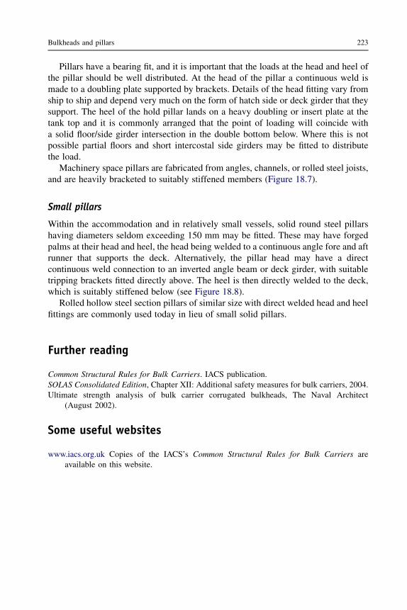
Pillars have a bearing fit, and it is important that the loads at the head and heel ofthe pillar should be well distributed. At the head of the pillar a continuous weld ismade to a doubling plate supported by brackets. Details of the head fitting vary fromship to ship and depend very much on the form of hatch side or deck girder that theysupport. The heel of the hold pillar lands on a heavy doubling or insert plate at thetank top and it is commonly arranged that the point of loading will coincide witha solid floor/side girder intersection in the double bottom below. Where this is notpossible partial floors and short intercostal side girders may be fitted to distributethe load.
Machinery space pillars are fabricated from angles, channels, or rolled steel joists,and are heavily bracketed to suitably stiffened members (Figure 18.7).
Small pillars
Within the accommodation and in relatively small vessels, solid round steel pillarshaving diameters seldom exceeding 150 mm may be fitted. These may have forgedpalms at their head and heel, the head being welded to a continuous angle fore and aftrunner that supports the deck. Alternatively, the pillar head may have a directcontinuous weld connection to an inverted angle beam or deck girder, with suitabletripping brackets fitted directly above. The heel is then directly welded to the deck,which is suitably stiffened below (see Figure 18.8).
Rolled hollow steel section pillars of similar size with direct welded head and heelfittings are commonly used today in lieu of small solid pillars.
Further reading
Common Structural Rules for Bulk Carriers. IACS publication.SOLAS Consolidated Edition, Chapter XII: Additional safety measures for bulk carriers, 2004.Ultimate strength analysis of bulk carrier corrugated bulkheads, The Naval Architect
(August 2002).
Some useful websites
www.iacs.org.uk Copies of the IACS’s Common Structural Rules for Bulk Carriers areavailable on this website.
Bulkheads and pillars 223

19 Decks, hatches,and superstructures
Chapter OutlineDecks 226
Deck plating 226Deck stiffening 229
Hatches 229Hatch coamings 232Hatch covers 232
Bulwarks 235Construction of bulwarks 235
Superstructures and deckhouses 237Forecastle 237Bridge structures 238Poop structure 238Passenger ship superstructures 238Weathertight doors 240
Further reading 240Some useful websites 240
Decks at different levels in a ship serve various functions; they may be eitherwatertight decks, strength decks, or simply cargo and passenger accommodationdecks. Watertight decks are fitted to maintain the integrity of the main watertight hull,and the most important is the freeboard deck, which is the uppermost deck havingpermanent means of closing all openings in the exposed portions of that deck.Although all decks contribute to some extent to the strength of the ship, the mostimportant is that which forms the upper flange of the main hull girder, called the‘strength deck’. Lighter decks that are not watertight may be fitted to provide plat-forms for passenger accommodation and permit more flexible cargo-loadingarrangements. In general cargo ships these lighter decks form tweens that providespaces in which goods may be stowed without their being crushed by a large amountof other cargo stowed above them.
To permit loading and discharging of cargo, openings must be cut in the decks, andthese may be closed by nonwatertight or watertight hatches. Other openings arerequired for personal access through the decks, and in way of the machinery spacecasing openings are provided that allow the removal of machinery items whennecessary, and also provide light and air to this space. These openings are protected
Ship Construction. DOI: 10.1016/B978-0-08-097239-8.00019-2
Copyright � 2012 Elsevier Ltd. All rights reserved.

by houses or superstructures, which are extended to provide accommodation andnavigating space. Forward and aft on the uppermost continuous deck a forecastle andoften a poop may be provided to protect the ends of the ship at sea.
Decks
The weather decks of ships are cambered to facilitate the draining of water from thedecks in heavy weather. The camber may be parabolic or straight,the latter beingpreferred in many cases to allow panel lines to be used for the production of the deckpanels. There may be advantages in fitting horizontal decks in some ships, particularlyif containers are carried and regular cross-sections are desired. Short lengths ofinternal deck or flats are as a rule horizontal.
Decks are arranged in plate panels with transverse or longitudinal stiffening, andlocal stiffening in way of any openings. Longitudinal deck girders may support thetransverse framing, and deep transverses the longitudinal framing (see Figure 19.1).
Deck plating
The heaviest deck plating will be found abreast the hatch openings of the strengthdeck. Plating that lies within the line of the hatch openings contributes little to thelongitudinal strength of the deck and it is therefore appreciably lighter. As the greatestlongitudinal bending stresses will occur over the midship region, the greatest deckplate thickness is maintained over 40% of the length amidships, and it tapers toa minimum thickness permitted at the ends of the ship. Locally, the plating thicknessmay be increased where higher stresses occur owing to discontinuities in the structureor concentrated loads.
Other thickness increases may occur where large deck loads are carried, wherefork-lift trucks or other wheeled vehicles are to be used, and in way of deep tanks.Where the strength deck plating exceeds 30 mm it is to be Grade B steel and if itexceeds 40 mm Grade D over the midships region, at the ends of the superstructure,and in way of the cargo hold region in container ships. The stringer plate (i.e. thestrake of deck plating adjacent to the sheerstrake) of the strength deck, over themidship region and container ship cargo hold area, of ships less than 260 meters inlength, is to be of Grade B steel if 15–20 mm thick, Grade D if 20–25 mm thick, andGrade E if more than 25 mm thick. Where the steel deck temperatures fall below 0 �Cin refrigerated cargo ships the steel will be of Grades B, D, and E depending onthickness.
On decks other than the strength deck, the variation in plate thickness is similar,but lighter scantlings are in use.
Weather decks may be covered with wood sheathing or an approved composition(usually composition for reasons of economy), which not only improves theirappearance, but also provides protection from heat in way of any accommodation.Since wood provides some additional strength, reductions in the deck plate thicknessare permitted, and on superstructure decks the plating thickness may be further
226 Ship Construction

Decklongitudinal
Tripping bracket
Deck plating
Plateweb
KneeFacing flat
DECK TRANSVERSE
Deck plating
LONGITUDINAL DECK GIRDER
Plateweb
Trippingbracket
Transversedeck beam
Facing flat
Deck plating
Decklongitudinal
Trippingbracket
Plateweb
Facing flat
SECTIONSide frame
Side shell
Deck plating
Deckbeam
Plate web
Facing flat
Trippingbracket
SECTION
Figure 19.1 Deck supports.
Deck
s,hatch
es,andsuperstru
ctures227

decreased within deckhouses, if sheathed. Before fitting any form of sheathing thedeck is treated to prevent corrosion between the deck plating and sheathing (seeFigure 19.2).
Any openings abreast the hatch openings in a deck are kept to a minimum and clearof the hatch corners. If such openings are cut, compensation is required to restore thesectional area of deck. All large openings in the decks have well-rounded corners, toavoid stresses, with insert plates fitted, unless the corners are parabolic or ellipticalwith the major axis fore and aft, local stress concentrations being reduced if the lattertype of corner is cut (see Figure 19.4).
Bulwark stay
Bulwark
Beam knee
Side frames
Hatch end beam
Pillar
Deck longitudinalsDeck plating
Deck plating
Deckbeams
(a) TRANSVERSELYFRAMED DECK
Hatch side girderDeck plating
Hatchcoaming
Deck transverses
(b) LONGITUDINALLYFRAMED DECK
Hatchcoaming
Figure 19.2 Deck sheathing.
228 Ship Construction

Deck stiffening
Decks may be framed transversely or longitudinally, but outside the line of openings itis preferred that longitudinal framing should be adopted for the strength deck.
When the decks are longitudinally framed the scantlings of the longitudinals aredependent on their spacing, the length of ship, whether they are inside or outside theline of hatch openings, their span, and the deck loading. Deck transverses support thelongitudinals, and these are built from a deep web plate with flange or welded faceflat, and are bracketed to the side frame (Figure 19.1). Within the forward 7.5% of theship’s length, the forecastle and weather deck transverses are closely spaced and thelongitudinal scantlings increased, the additional transverse and longitudinal stiffeningforward being designed to avoid buckling of the deck plating on impact when ship-ping seas.
Transversely framed decks are fitted with deck beams at every frame, and thesehave scantlings that are dependent on their span, spacing, and location in the ship.Those fitted right forward on weather decks, like the longitudinal framing forward,have heavier scantlings, and the frame spacing is also decreased in this region so theywill be closer together. Beams fitted in way of deep tanks, peak tanks, and oil bunkersmay also have increased scantlings as they are required to have the same rigidity asthe stiffeners of the tank boundary bulkheads. Deck beams are supported by longi-tudinal deck girders that have similar scantlings to deck transverses fitted with anylongitudinal framing. Within the forward 7.5% of the ship’s length these deck girdersare more closely spaced on the forecastle and weather decks. Elsewhere the spacing isarranged to suit the deck loads carried and the pillar arrangements adopted. Eachbeam is connected to the frame by a ‘beam knee’ and abreast the hatches ‘half beams’are fitted with a suitable supporting connection at the hatch side girder (seeFigure 19.3).
Both longitudinals and deck beam scantlings are increased in way of cargo deckswhere fork-lift trucks and other wheeled vehicles, which cause large point loads,are used.
In way of the hatches fore and aft side girders are fitted to support the inboard endsof the half beams and transverses. At the ends of the hatches heavy transverse beamsare fitted and these may be connected at the intersection with the hatch side girder byhorizontal gusset plates (Figure 19.4). Where the deck plating extends inside thecoamings of hatches amidships the side coaming is extended in the form of taperedbrackets.
Hatches
The basic regulations covering the construction and means of closing hatches inweathertight decks are contained within the Conditions of Assignment of Freeboardof the Load Line Convention (see Chapter 31). Lloyd’s Register provides formulae fordetermining the minimum scantlings of steel covers, which will be within therequirements of the Load Line Convention. Only the maximum permitted stresses and
Decks, hatches, and superstructures 229
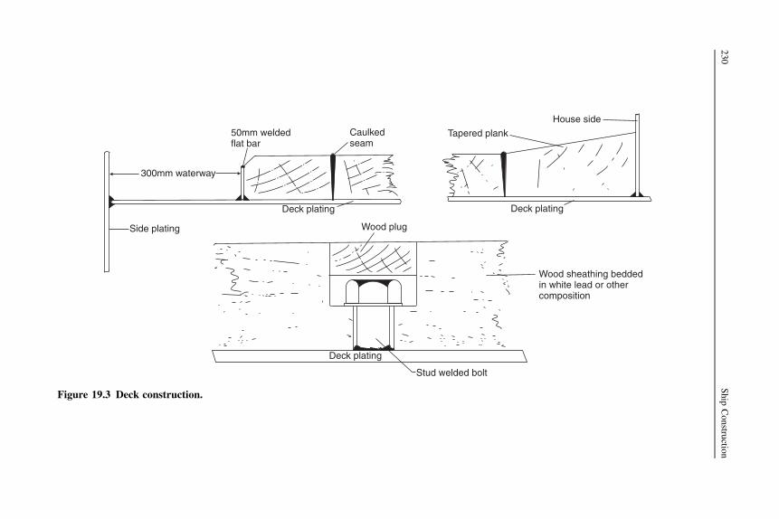
Stud welded bolt
Wood sheathing beddedin white lead or othercomposition
Deck plating
Wood plug
Deck plating
Tapered plank
House side
Deck plating
Side plating
300mm waterway
50mm weldedflat bar
Caulkedseam
Figure 19.3 Deck construction.
230
Ship
Constru
ction

athwartshipsELLIPTICAL HATCH CORNER
2fore and aft
Hatch side girder
Deep hatch andbeam (ortransverse)
Gusset plate
Insert plate
RADIUSED HATCH CORNER
Well clear ofradius
One frame spacefore and aft
One frame spacefore and aft
1
Patent hatch cover
Hatch coaming
Deck
Longitudinal stiffener
HATCH COAMING
Offset bulb stiffener
Offset bulb plate
Deep hatchend beam (ortransverse)
Gusset plate(see detail) Hatch side girder
Deck
Hatchcoaming
Deck
Hatch
coam
ing
For’d
Aft
Radius
Figure 19.4 Hatch openings.
Deck
s,hatch
es,andsuperstru
ctures231

deflections of covers under specified loadings are given by the Load Line Convention.Under the Convention, ships fitted with approved steel covers having direct securingarrangements may have reduced B-100 or B-60 freeboards if they meet the subdi-vision requirements, but in general they are assigned standard cargo ship Type Bfreeboards. If steel pontoon-type covers that are self-supporting and have no directsecuring arrangements are fitted, then the standard Type B freeboard only is assigned.The use of portable beams fitted with wood or light steel covers and tarpaulins asa traditional hatch covering has almost disappeared. If used, then the ship has anincreased Type B freeboard, i.e. there is a draft penalty. This means that most ships arefitted exclusively with the stronger stiffened self-supporting steel covers.
Hatch coamings
Heights of coamings and cover closing arrangements in some instances depend on thehatch position. The positions differentiate between regions that are more exposed thanothers. Position 1 indicates that the hatch is on the exposed freeboard deck, raisedquarter deck, or superstructure decks within 25% of the ship’s length from forward.Position 2 indicates that the hatch is located on exposed superstructure decks abaft theforward 25% of the ship’s length.
Hatches that are at Position 1 have coamings at least 600 mm high and those atPosition 2 have coamings at least 450 mm high, the height being measured aboveany deck covering. Provision is made for lowering these heights or omitting thecoaming altogether if directly secured steel covers are fitted and it can be shown thatthe safety of the ship would not be impaired in any sea condition. Where the coamingheight is 600 mm or more the upper edge is stiffened by a horizontal bulb flat andsupporting stays to the deck are fitted. Coamings less than 600 mm high are stiffenedby a cope or similar bar at their upper edge. The steel coamings extend down to thelower edge of the deck beams, which are then effectively attached to the coamings(Figure 19.4).
Hatch covers
A number of patent steel covers, such as those manufactured by MacGregor CargotecGroup AB and TTS Marine ASA, are available that will comply with the require-ments outlined by the International Conference on Load Lines 1966 and are inaccordance with the requirements of the classification societies. The means ofsecuring the hatches and maintaining their watertightness is tested initially and atperiodic surveys. These patent covers vary in type, the principal ones being fore andaft single pull, folding, piggy-back, pontoon, and side rolling. These are illustrated inFigures 19.5 and 19.6. Single pull covers may be opened or closed by built-in electricmotors in the leading cover panel (first out of stowage) that drive chain wheels, one oneach outboard side of the panel. Each panel wheel is permanently engaged on a fixedchain located along each hatch side coaming. In operation the leading panel pushesthe others into stowage and pulls them into the closed position. Alternatively, singlepull covers are opened or closed by hydraulic or electric motors situated on the hatch
232 Ship Construction

45° entry to wheel rail
Hatchcover
Coaming
45°
Wheel rail
(a) FOLDING HATCH COVERS
Slotted hinges
Motor drive inleading panel
Wheel ramp
Cleat halves – cover mounted
Hydraulic cylinderexternally mounted
Closing arm
Securing hook
Closing arm pedestalStowing arm pedestal
Stowing arm
Hinged sheave
Wire pendant
Hauling eyeplateHinge
Panel 1
Panel 2
Panel 3
Wheel(b) SINGLE PULL
HATCH COVERS
(c) DIRECT PULLHATCH COVERS
Figure 19.5 Hatch covers—1.
Deck
s,hatch
es,andsuperstru
ctures233

end coaming at the ship’s center line, driving endless chains running along the fulllength of the hatch side coaming port and starboard and connected to the leadingpanel. Vertical stowage of panels is at one end of the hatch and covers may havea nesting characteristic if space is at a premium; also, on large hatches opening maybe to both ends with vertical stowage at each end. Folding covers may be of direct pulltype where suitable lifting gear is carried onboard or can be opened or closed byexternally mounted hydraulic cylinders actuating the leading panels. Piggybackcovers permit horizontal stowage of panels, avoiding fouling of lifting devicesparticularly in way of very large openings such as on bulk carriers and containerships, where the hatch need only be partially open for working. The covers consist ofa dumb panel that is raised by high lift cylinders and a motorized panel that is rolled
Closed position
HatchcoamingSection through
cross jointbetweenpanels
Section throughsides and ends
Rubbergasket
Dumb panel raised by high-lift cylinders
Motorized panel rolled underneath
(b) ‘PIGGY-BACK’ HATCH COVER
Both panels moved ‘piggy-back’ styleto fully open position (port or starboard)
Rubber gasket
(c) WEATHERTIGHT GASKETS FORPATENT HATCH COVERS
(a) ROLLING HATCH COVERS
Figure 19.6 Hatch covers—2.
234 Ship Construction

underneath the dumb panel. Both panels can then be moved ‘piggy-back’ style to thefully opened hatch position port or starboard or partially opened position fore and aft.Pontoon covers are commonly used on container ships, being lifted by the ships’ orshore cranes with the container spreader. They are closed weathertight in a similarmanner to the other patent covers. Side rollings are very common on large bulkcarriers and can operate on similar principles to the single pull cover except that theyremain in the horizontal stowed position when the hatch is open. Various other formsof cover are marketed, and tween deck steel covers are available to be fitted flush withthe deck, which is essential nowadays when stowing cargoes in the tweens. To obtainweathertightness the patent covers have mating boundaries fitted with rubber gaskets;likewise at the hatch coamings, gaskets are fitted and hand or automatically operatedcleats are provided to close the covers (see Figure 19.6). The gasket and cleatarrangements will vary with the type of cover.
Pontoon covers of steel with internal stiffening may be fitted, these being con-structed to provide their own support without the use of portable beams. Each pontoonsection may span the full hatch width, and cover perhaps one-quarter of the hatchlength. They are strong enough to permit Type B freeboards to be assigned to the ship,but to satisfy the weathertightness requirements they are covered with tarpaulins andbattening devices.
Where portable beams are fitted wood or stiffened steel plate covers may be used.These and the stiffened beams have the required statutory scantlings but an increase inthe freeboard is the penalty for fitting such covers. The beams sit in sockets at thehatch coamings and the covers are protected by at least two tarpaulins. At the coamingthe tarpaulins are made fast by battens and wedges fitted in cleats, and the sections ofthe cover are held down by locked bars or other securing arrangements (seeFigure 19.7).
Bulwarks
Bulwarks fitted on weather decks are provided as protection for personnel and arenot intended as a major structural feature. They are therefore of light scantlings,and their connections to the adjacent structures are of some importance if highstresses in the bulkwarks are to be avoided. Freeing ports are cut in bulwarks,forming wells on decks in order that water may quickly drain away. The requiredarea of freeing ports is in accordance with the Load Line Convention requirement(see Chapter 31).
Construction of bulwarks
Bulwarks should be at least 1 m high on the exposed freeboard and superstructuredecks, but a reduced height may be permitted if this interferes with the working of theship. The bulwark consists of a vertical plate stiffened at its top by a strong rail section(often a bulb angle or plate) and is supported by stays from the deck (Figure 19.7). Onthe forecastle of ships assigned B-100 and B-60 freeboards the stays are more closely
Decks, hatches, and superstructures 235

Cleat
Coaming
Round bar
Web
Flat
Hatchbeam
TarpaulinsMolded section retainingwood covers
Batten retaining tarpaulin
Bulwark stay(cut from offsetbulb section)
Welded bulb angle section
Bulwark
Flange
Freeingport
Wedge
Cleat
Wood covers
Heavy insert platein web at socket
Vertical stiffener formingsocket in whichbeam sits
Coaming
HATCHBEAM
SECTION
Batten
PLAN AT HORIZONTAL STIFFENER
WedgeSide frame
Deck Deck
Stay
Horizontal stiffener
Half beam
BULWARK DETAIL
Figure 19.7 Bulwark detail and hatch with portable beams and wood covers.
236
Ship
Constru
ction

spaced. Where the bulwark is cut for any reason, the corners are well rounded andcompensation is also provided. No openings are permitted in bulwarks near the end ofsuperstructures.
Superstructures and deckhouses
Superstructures may be defined as those erections above the freeboard deck thatextend to the ship’s side or almost to the side. Deckhouses are those erections on deckthat are well within the line of the ship’s side. Both structures are of importance in theassignment of the load line as they provide protection for the openings throughthe freeboard deck. Of particular importance in this respect are the end bulkheads ofthe superstructures, particularly the bridge front, which is to withstand the force ofany seas shipped. The bridge structure amidships or the poop aft are, in accordancewith statutory regulations, provided as protection for the machinery openings. It ispossible, however, to dispense with these houses or superstructures and increaseconsiderably the scantlings of the exposed machinery casing, but in other than verysmall vessels it is unlikely that such an arrangement would be adopted. Unless anexcessive sheer is provided on the uppermost deck it is necessary to fit a forecastleforward to give added protection in a seaway. Each structure is utilized to the full, theafter structure carrying virtually all the accommodation in modern ships. The crewmay be located all aft in the poop structure or partly housed in any bridge structurewith the navigating spaces. Passenger liners have considerable areas of superstruc-tures covering tiers of decks and these will house the majority of passengers and someof the crew.
Of great structural importance is the strength of the vessel where superstructuresand deckhouses terminate and are noncontinuous. At these discontinuities, discussedin Chapter 8, large stresses may arise and additional strengthening will be requiredlocally as indicated in the following notes on the construction. Long superstructuresexceeding 15% of the ship’s length and extending within 50% of the vessel’s lengthamidships receive special consideration as they contribute to the longitudinal strengthof the ship, and as such must have scantlings consistent with the main hull strengthmembers.
Forecastle
Sea-going ships must be fitted with a forecastle that extends at least 7% of the ship’slength aft of the stem, and a minimum height of the bow at the forecastle deck abovethe summer load line is stipulated. By increasing the upper deck sheer at the forwardend to obtain the same height of bow, the forecastle might be dispensed with, but inpractice this construction is seldom found. The side and end plating of the forecastlehas a thickness that is dependent on the ship’s length and the frame and stiffenerspacing adopted, the side plating being somewhat heavier than the aft end plating. Ifa long forecastle is fitted such that its end bulkhead comes within 50% of the ship’slength amidships, additional stiffening is required.
Decks, hatches, and superstructures 237

Bridge structures
The side of bridge superstructures whose length exceeds 15% of the ship’s length willhave a greater thickness than the sides of other houses, the scantling being similar tothat required for the ship’s side shell. All bridge superstructures and midship deck-houses will have a heavily plated bridge front, and the aft end plating will be lighterthan the front and sides. Likewise the stiffening members fitted at the forward end willhave greater scantlings than those at the sides and aft end. Additional stiffening in theform of web frames or partial bulkheads will be found where there are large erectionsabove the bridge deck. These are intended to support the sides and ends of the housesabove and are preferably arranged over the watertight bulkheads below. Underconcentrated loads on the superstructure decks, for example under lifeboat davits,web frames are also provided.
The longer bridge superstructure that is transmitting the main hull girder stressesrequires considerable strengthening at the ends. At this major discontinuity, the upperdeck sheerstrake thickness is increased by 20%, the upper deck stringer plate by 20%,and the bridge side plating by 25%. The latter plating is tapered into the upper decksheerstrake with a generous radius, as shown in Figure 19.8a, stiffened at its upperedge, and supported by webs not more than 1.5 m apart. At the ends of short bridgesuperstructures less strengthening is required, but local stresses may still be high andtherefore the upper deck sheerstrake thickness is still increased by 20% and the upperdeck stringer by 20%.
Poop structure
Where there is no midship deckhouse or bridge superstructure the poop front will beheavily constructed, its scantlings being similar to those required for a bridge front. Inother ships it is relatively exposed and therefore needs adequate strengthening in allcases. If the poop front comes within 50% of the ship’s length amidships, thediscontinuity formed in the main hull girder is to be considerably strengthened, as fora long bridge exceeding 15% of the ship’s length. Where deckhouses are built abovethe poop deck these are supported by webs or short transverse bulkheads in the samemanner as those houses fitted amidships. The after end of any poop house will haveincreased scantlings since it is more exposed than other aft end house bulkheads.
Passenger ship superstructures
It is shown in Chapter 8 that with conventional beam theory the bending stressdistribution is linear, increasing from zero at the neutral axis to a maximum at theupper deck and bottom. If a long superstructure is fitted the stress distribution remainslinear and the strength deck is above the upper deck in way of the superstructure deck.If a short superstructure is fitted the stress distribution will be broken at the upperdeck, which is the strength deck, the stresses in the superstructure deck being less thanthose in the upper deck. The long superstructure is referred to as an ‘effectivesuperstructure’, the erections contributing to the overall strength of the hull girder,and therefore they are substantially built.
238 Ship Construction

Greater than 15%of length
Clip
Clip
Clip
Clip
Clip
Clip
House side
House side
Plate webs
Bulwark Bulwark stay
Door
Bridge front
Door
Rubbergasket
DOOR SECTION
HINGE DETAIL
ELEVATION AT END OF LONG BRIDGE
PLAN AT UPPER DECK
DETAIL OF DOOR CLIP
(b) WEATHERTIGHT DOOR
Hinge
Hinge
Rubbergasket
Rubber gasketBridge deck Bridge front
Radiused platewith stiffenededge Handle
Flatstiffener
Bridge plating + 25% thickness
Deck stringer + 20% thickness
Sheerstrake + 20% thickness
(a) LONG BRIDGE
Figure 19.8 Effective superstructure connection and weathertight door.
Deck
s,hatch
es,andsuperstru
ctures239

In passenger ships with large superstructures the present practice is to make thestructure effective with adequate scantlings. Some older ships have been fitted withexpansion joints that are in effect transverse cuts introduced to relieve the hullbending stresses in the houses. It has been shown that at the end of deck erections thestresses do not conform to beam theory and the ends are ineffective in contributing tothe longitudinal strength. The expansion joints were therefore so arranged that this‘end effect’ extended from joint to joint, and lighter scantlings were then permittedfor the superstructure. Unfortunately the expansion joint often provided an ideal‘notch’ in the structure from which cracks initiated. Aluminum alloy superstructuresoffer an alternative to the use of expansion joints, since the low modulus of elasticityof the material results in lower stresses in the houses than would be the case witha steel superstructure, all other considerations being equal.
Weathertight doors
The integrity of houses on the freeboard and other decks that protect the openings inthese decks must be maintained. Access openings must be provided to the houses andweathertight doors are fitted to these openings. These must comply with therequirements of the Load Line Convention (see Chapter 31) and are steel doors thatmay be secured and made watertight from either side. Weathertightness is maintainedby a rubber gasket at the frame of the door (see Figure 19.8b).
Further reading
Common Structural Rules for Bulk Carriers. IACS publication.International Conference on Load Lines, 1966. IMO publication (IMO 701E), 2005 edition.
Some useful websites
www.macgregor-group.com Hatch cover types and details.www.tts-marine.com Hatch cover types and details.www.iacs.org.uk See ‘Guidelines and Recommendations’: Recommendation 14 ‘Hatch cover
securing and tightness’; Recommendation 15 ‘Care and survey of hatch covers of drycargo ships—Guidance to owners’; ‘Common structural rules for bulk carriers’.
http://exchange.dnv.com/publishing Includes requirements for large superstructures.
240 Ship Construction

20 Fore end structure
Chapter OutlineStem 241Bulbous bows 243Chain locker 244
Construction of chain locker 244Hawse pipes 248Bow steering arrangements 248Bow thrust units 248Some useful websites 248
Consideration is given in this chapter to the structure forward of the collision bulk-head. The chain locker is included as it is usually fitted forward of the collisionbulkhead below the second deck or upper deck, or in the forecastle itself. An overallview of the fore end structure is shown in Figures 20.1 and 20.2, and it can be seen thatthe panting stiffening arrangements are of particular importance. These have alreadybeen dealt with in detail in Chapter 17 as they are closely associated with the shellplating.
On the forecastle deck the heavy windlass seating is securely fastened and givenconsiderable support. The deck plating thickness is increased locally, and smallerpillars with heavier beams and local fore and aft intercostals, or a center-line pillarbulkhead, may be fitted below the windlass.
Stem
On many conventional ships a stem bar, which is a solid round bar, is fitted from thekeel to the waterline region, and a radiused plate is fitted above the waterline to formthe upper part of the stem. This forms what is referred to as a ‘soft nose’ stem, whichin the event of a collision will buckle under load, keeping the impact damage toa minimum. Older ships had solid bar stems that were riveted and of square section,and as the stem had no rake it could cause considerable damage on impact because ofits rigidity. Small ships such as tugs and trawlers may still have a solid stem barextending to the top of the bow, and some existing large passenger ships may havesteel castings or forgings forming the lower part of the stem. A specially designedbow is required for ships assigned ‘Icebreaker’ notation and additional scantlings arerequired for the stems of ships assigned other ice classes (see Chapter 17).
Ship Construction. DOI: 10.1016/B978-0-08-097239-8.00020-9
Copyright � 2012 Elsevier Ltd. All rights reserved.

Stiffener
Breast hook
Solid round stem bar
STEM SECTIONS
Panting stringer
Panting beam
PLAN OF STRINGER I
Washplate
Fo’c’sle deck
Deepgirder
Upper deck
Pillar
Deep floors
Chainlocker
Pillar
Deck girder
Girder
FOREPEAK
TANK
Pillar
Stringer III
Breast hookStringer II
Stringer I
Solid round stem bar
Breast hook
PillarPantingbeam
Stiffener
ELEVATION AT SHIP’S CENTER LINE
WASH PLATE
WASH PLATE
MUD BOX
WASH PLATE
Figure 20.1 Fore end construction.
242
Ship
Constru
ction

The solid round bar is welded inside the keel plate at its lower end, and inside theradiused stem plate at its upper end, the shell being welded each side (Figure 20.1).It is necessary to support that part of the stem that is formed by radiused plates with‘breast hooks’, i.e. horizontal plate webs, between the decks and below the lowestdeck, in order to reduce the unsupported span of the stem. Where the plate radius islarge, further stiffening is provided by a vertical stiffener on the center line. Thethickness of these plates will be in excess of that required for the side shell forward,but the thickness may taper to that of the side shell at the stem head.
Bulbous bows
Vessels operating at higher speeds, and those with high block coefficients, are oftenfound to have a bulbous or protruding bow below the waterline. The arguments forand against fitting some form of bulbous bow are the province of textbooks on navalarchitecture, but it may be indicated that like most peculiarities of the immersed hull
Floors
Collision bulkhead
Panting stringers
Chain locker
Bulkhead stiffeners
Stem bar
Panting beams
Plate stem
Wash bulkhead
Figure 20.2 Fore end structure.
Fore end structure 243

form this feature is usually intended to reduce the vessel’s resistance to motion undercertain conditions.
From the construction point of view the bulbous bow does not present any greatdifficulty if this aspect has been considered when the bulb form is designed. Ingeneral, however, a greater degree of plate curvature is involved, unless a ratherconvenient cylindrical form is adopted and fitted into the bow as a single unit. Thishas in fact been done successfully; but in general the protrusion forms a continuationof the side shell. Floors are fitted at every frame space in the bulb, and a center linewash bulkhead is introduced when the bulb is large. Transverses are fitted at aboutevery fifth frame in long bulbs (see Figure 20.3). Smaller bulbs have a center-line webbut not a wash bulkhead; and in all bulbous bows horizontal diaphragm plates arefitted. Shell plating covering the bulb has an increased thickness similar to that ofa radiused plate stem below the waterline. This increased thickness should inparticular cover any area likely to be damaged by the anchors and chains, and indesigning the bow fouling of the anchors should be taken into consideration.
Chain locker
A chain locker is often arranged in the position forward of the collision bulkheadshown in Figure 20.1, below either the main deck or the second deck. It can also befitted in the forecastle or aft of the collision bulkhead, in which case it must bewatertight and have proper means of drainage. Chain locker dimensions are deter-mined in relation to the length and size of cable, the depth being such that the cable iseasily stowed, and a direct lead at all times is provided to the mouth of the chain pipe.Port and starboard cables are stowed separately in the locker, and the inboard ends ofeach are secured to the bottom of the center-line bulkhead or underside of deck (seeFigure 20.4). It is desirable to have an arrangement for slipping the cable from outsidethe chain locker.
Construction of chain locker
The locker does not as a rule have the same breadth as the ship, but has conventionallystiffened forward and side bulkheads, the stiffeners being conveniently arrangedoutside the locker if possible to prevent their being damaged. A false bottom may beformed by perforated plates on bearers arranged at a height above the floor of thelocker. Where fitted this provides a mudbox that can be cleaned and is drained bya center-line suction, the bottom plating sloping inboard. To separate the locker intoport and starboard compartments a center-line bulkhead is fitted. This bulkhead doesnot extend to the crown of the locker, but allows working space above the twocompartments. Access to the bottom of the locker is provided by means of foot holescut in the bulkhead, and the stiffeners fitted to this bulkhead are of the vertical flushcope bar type. Any projections that would be damaged by the chains are thus avoided.The upper edge of the bulkhead is similarly stiffened and may provide a standingplatform, with a short ladder leading from the hatch in the deck forming the crown of
244 Ship Construction
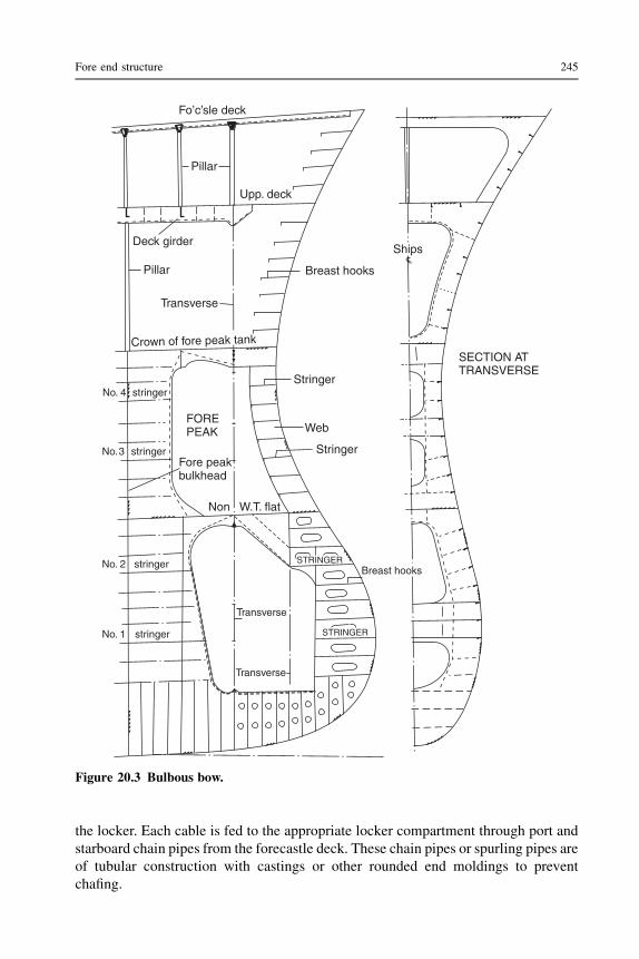
the locker. Each cable is fed to the appropriate locker compartment through port andstarboard chain pipes from the forecastle deck. These chain pipes or spurling pipes areof tubular construction with castings or other rounded end moldings to preventchafing.
Ships
SECTION ATTRANSVERSE
Fo’c’sle deck
Breast hooks
Pillar
Upp. deck
Deck girder
Pillar
Transverse
Crown of fore peak tank
Stringer
Web
Stringer
No. 4 stringer
No. 2 stringer
No. 1 stringer
FOREPEAK
Fore peakbulkhead
Non W.T. flat
Transverse
Transverse
Breast hooksSTRINGER
No.3 stringer
STRINGER
L
Figure 20.3 Bulbous bow.
Fore end structure 245

Fo’c’sle deck
Chain pipe
Hatch
Stiffening outside locker
L
Ladder
Stiffener
Foot holes
Center-line bulkheadCentre linebulkhead
Ship’s
PLANCope barstiffeners
Cableanchorage
False bottomCenter-line bulkhead
False bottom
CHAINANCHORAGE
Shackle for chainWelded lugs
Welded lugs
Mud box
DoublingPinDoubling
Cope stiffenerCenter-line bulkhead
Figure 20.4 Chain locker construction.
246 Ship Construction

Casting at forecastle deck
Wood sheathing
WeldWeld
Side shell
Local insertplate
CONSTRUCTION
Tubular sectionhawse pipe
Weld
Weld
Casting atshell
OVERALLARRANGEMENT
Chainlocker
Upp. dk. Hatch
Chain or spurling pipe
Windloss
Hawse pipe
Foc’s’le deck
Figure 20.5 Hawse pipes.
Fore
endstru
cture
247
Hawse pipes
To provide an easy lead for the cable from the windlass to the anchors, the hawsepipes must be carefully fitted. In the past it was not uncommon for a temporary scalemodel of the relevant fore end structure to be constructed, and the positions of thehawse pipes experimented with in order to obtain the best chain lead to ensure theanchor could be raised and lowered smoothly and housed properly. Today this can beachieved with the CAD hull model.
Tubular hawse pipes are generally fabricated, and castings are welded at the shelland deck to prevent chafing (see Figure 20.5). Additional stiffening in way of thehawse pipes is required at the side shell. On higher speed vessels a recess is oftenprovided in the shell for anchor stowage; this helps to reduce any drag caused by thestowed anchor and prevents serious damage in the event of a collision.
Bow steering arrangements
Double-ended ferries are provided with a rudder at either end that is locked in positionwhen it is at the fore end of the vessel under way.
Bow thrust units
For maneuvering in confined waters at low speeds, lateral bow thrust units areparticularly useful. These are often found in research vessels, or drilling platformvessels where very accurate positioning must be maintained. They are also to befound in large ships and cross-channel vessels where they are provided as an aid todocking. The thrust unit consists as a rule of controllable pitch or reversible impellerfitted in an athwartships watertight tunnel. Control of the unit is from the bridge, butthe driving motor is in way of the impeller. Thrust provided by the impellers is low;16 tonnes is perhaps the largest fitted, but the unit size does not need to be large assmall thrusts are very effective. It is true, however, that the greatest thrust is providedat zero speed and as the vessel gets under way the unit becomes much less effective.
From a construction point of view the most important feature is the provision offairing sections at the ends of the athwartship tunnel in way of the shell. It has beenshown that an appreciable increase in hull resistance and hence power may result ifthis detail is neglected. The best way of avoiding this is to close the tunnels at eitherend when they are not in use. This is possible, flush-mounted, butterfly action,hydraulically operated doors being available for this purpose.
Some useful websites
www.brunvoll.no For details of tunnel and azimuth bow thrust units.
248 Ship Construction

21 Aft end structure
Chapter OutlineStern construction 252Stern frame 252Rudders 254
Rudder construction 254Rudder pintles 254Rudder stock 256Rudder bearing 256Rudder trunk 256
Steering gear 256Sterntube 258Shaft bossing and ‘A’ brackets 258
Construction of bossing and ‘A’ brackets 260Propellers 260
Controllable pitch propellers 260Shrouded propellers 262
Electric podded propulsors 262Further reading 264Some useful websites 264
Considerable attention is paid to the stern in order to improve flow into and away fromthe propeller. The cruiser stern (see Figure 21.1) was for many years the favored sterntype for ocean-going ships, but today most of these vessels have a transom stern (seeFigure 21.2). A cruiser stern presents a more pleasant profile and is hydrodynamicallyefficient, but the transom stern offers a greater deck area aft, is a simpler construction,and can also provide improved flow around the stern. It is interesting to note that theQueen Mary 2 has a combined stern, the upper part being of cruiser stern form forgood seakeeping and the lower part being of transom form for efficienthydrodynamics.
Many forms of rudder are available and the type and form fitted is intended to givethe best maneuvering characteristics. Both the shape of the stern and the rudder typewill dictate the form of the stern frame, and this will be further influenced by therequired propeller size. Of particular importance at the after end are the arrangementsthat permit both the propeller shaft and the rudder stock to pierce the intact watertighthull. The safety of the ship may depend on these arrangements. Where more than onescrew propeller is to provide the thrust required to propel the ship, bossings or ‘A’
Ship Construction. DOI: 10.1016/B978-0-08-097239-8.00021-0
Copyright � 2012 Elsevier Ltd. All rights reserved.

‘x’
Cant beam
Cant beam
Cant beam
PLAN AT UPPERDECK
Girder
Girder
Girder Ship’s
‘x’
Poop deck
SECTION ‘X’–‘X’
Cant beam
Steering flat
Upper deck
Cant frame
Stern frame
Poop deck
Bracket Deck centre-line girderBulkhead stiffener
Centre-line webUpper deck
Deck centre-line girder
Steering flat
Centre-line web Bulkhead stiffenerBracket
Centre-line girder
Bulkhead
Rudder trunk
Solid floors Flat
Cant beam
Figure 21.1 Cruiser stern.
250
Ship
Constru
ction

Upper deck
Rudder trunk
Steering flat
Inspectionmanhole
Verticalstiffeners
Solid floor
Wash plate
Floor
AFT PEAKTANK
Stern frame
Sideshell
Stern tube
Floor
Transom stern
Steering flat
BREAST HOOK
DETAIL
Breast hook
Ship’s
Upper deck
Aftpeakblkhd.
PLAN ATRUDDER TRUNK
FloorFloorFloorFloor
Ship’s
Inspection manhole
TRANSOM STERNLOOKING FOR’D
Centre-line
bulkhead(corrugated)
Figure 21.2 Transom stern.
Aft end structure 251

brackets will be fitted to support the outboard shafts. Whilst most ships are propellerdriven, other means of transmitting the power developed by the propulsion machineryinto a thrust to propel the ship are not uncommon. Water jets, for example, are nowa common feature on high-speed passenger and service craft.
Stern construction
As the cruiser stern overhang may be subjected to large slamming forces, a substantialconstruction with adequate stiffening is required. Solid floors are fitted at every framespace, and a heavy center-line girder is fitted right aft at the shell and decks. The sternplating is stiffened by cant frames or webs with short cant beams supporting the decksand led to the adjacent heavy transverse deck beam. Further stiffening of the plating isprovided, or adopted in lieu of cant frames, by horizontal stringers extending to thefirst transverse frame.
Cant frames are not required where the transom stern is adopted, as the flat sternplating may be stiffened with vertical stiffeners (Figure 21.2). Deep floors anda center-line girder are provided at the lower region of the transom stern construction.
Panting arrangements at the aft end are dealt with in Chapter 17.
Stern frame
It has already been indicated that the form of the stern frame is influenced by the sternprofile and rudder type. To prevent serious vibration at the after end there must beadequate clearances between the propeller and stern frame, and this will to a largeextent dictate its overall size.
The stern frame of a ship may be cast, forged, or fabricated from steel plate andsections. On larger ships it is generally either cast or fabricated, the casting beingundertaken by a specialist works outside the shipyard. To ease the casting problemwith larger stern frames and also the transport problem, it may be cast in more thanone piece and then welded together when erected in the shipyard. Fabricatedstern frames are often produced by the shipyard itself, plates and bars beingwelded together to produce a form similar to that obtained by casting (seeFigure 21.3). Forged stern frames are also produced by a specialist manufacturerand may also be made in more than one piece where the size is excessive or shapecomplicated.
Sternpost sections are of a streamline form, in order to prevent eddies beingformed behind the posts, which can lead to an increase in the hull resistance. Weldedjoints in cast steel sections will need careful preparation and preheat. Both the castand fabricated sections are supported by horizontal webs.
Two forms of stern frame are shown in Figure 21.3, one being a casting and theother fabricated, so that the similarity of the finished sections is indicated. Ofparticular interest is the connection of the stern frame to the hull structure for, if this isnot substantial, the revolving propeller supported by the stern frame may set up
252 Ship Construction
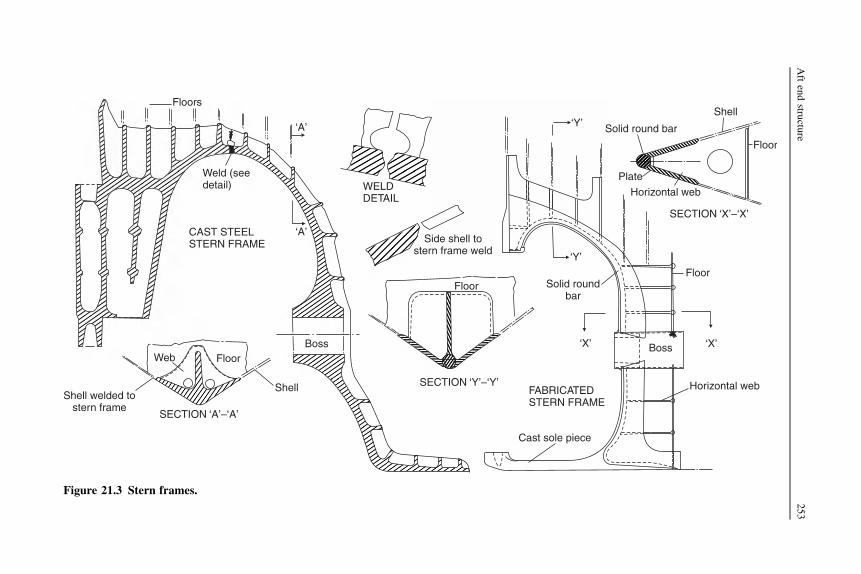
SECTION –‘A’‘A’
Web Floor
ShellShell welded to
stern frame
Boss
SECTION –‘Y’‘Y’
SECTION –‘X’‘X’
Cast sole piece
FABRICATEDSTERN FRAME
‘X’ ‘X’
Horizontal web
Boss
Floor
Shell
Floor
Solid round bar
Plate
Horizontal web
‘Y’
‘Y’
Solid roundbar
Floor
WELDDETAIL
Side shell tostern frame weld
Floors
‘A’
‘A’CAST STEELSTERN FRAME
Weld (seedetail)
Figure 21.3 Stern frames.
Aftendstru
cture
253

serious vibrations. The rudder post is carried up into the main hull and connected tothe transom floor, which has an increased plate thickness. Also, the propeller post maybe extended into the hull and connected to a deep floor, the lower sole piece beingcarried forward and connected to the keel plate. Side shell plates are directly weldedto the stern frame (Figure 21.3), a ‘rabbet’, i.e. a recess, sometimes being provided toallow the shell plate to fit flush with the sternpost section.
Rudders
Many of the rudders that are found on present-day ships are semi-balanced, i.e. theyhave a small proportion of their lateral area forward of the turning axis (less than20%). Balanced rudders with a larger area forward of the axis (25–30%) andunbalanced rudders with the full area aft of the axis are also fitted. The object ofbalance is to achieve a reduction in torque, since the center of lateral pressure isbrought nearer the turning axis. However, the fully balanced rudder will at low anglestend to drive the gear, which does not matter a great deal with power steering gears butis less satisfactory with any form of direct hand gear.
Designs of rudders are various, and patent types are available, all of which claimincreased efficiencies of one form or another. Two common forms of rudder areshown in Figure 21.4, each being associated with one of the stern frames shown inFigure 21.3.
Rudder construction
Modern rudders are of streamlined form except those on small vessels, and arefabricated from steel plate, the plate sides being stiffened by internal webs. Where therudder is fully fabricated, one side plate is prepared and the vertical and horizontalstiffening webs are welded to this plate. The other plate, often called the ‘closingplate’, is then welded to the internal framing from the exterior only. This may beachieved by welding flat bars to the webs prior to fitting the closing plate, and thenslot welding the plate as shown in Figure 21.4. Other rudders may have a cast frameand webs with welded side and closing plates, which are also shown in Figure 21.4.
Minor features of the rudders are the provision of a drain hole at the bottom witha plug, and a lifting hole that can take the form of a short piece of tube welded throughthe rudder with doubling at the side and closing plates. To prevent internal corrosionthe interior surfaces are suitably coated, and in some cases the rudder may be filledwith an inert plastic foam. The rudder is tested when complete under a head of water2.45 m above the top of the rudder.
Rudder pintles
Pintles on which the rudder turns in the gudgeons have a taper on the radius, anda bearing length that exceeds the diameter. Older ships may have a brass or bronzeliner shrunk on the pintles, which turn in lignum vitae (hardwood) bearings fitted in
254 Ship Construction
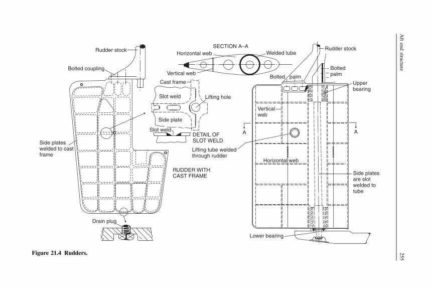
Drain plug
Lower bearing
Side platesare slotwelded totube
Upperbearing
Boltedpalm
Rudder stock
Bolted palm
Verticalweb
Horizontal web
Side plateswelded to castframe
SECTION A–AHorizontal web Welded tube
Vertical web
Lifting hole
DETAIL OFSLOT WELD
RUDDER WITHCAST FRAME
Lifting tube weldedthrough rudder
A A
Side plate
Slot weld
Slot weld
Rudder stock
Bolted coupling
Cast frame
Figure 21.4 Rudders.
Aftendstru
cture
255

the gudgeons. Modern practice is to use synthetic materials or composites for thebearings, and in some cases stainless steels for the liners. In either case lubrication ofthe bearing is provided by the water in which it is immersed. For many years it has notbeen found practicable to provide oil-lubricated metal bearings for the pintles, buta number of larger ships now have this innovation.
Rudder stock
Rudder stock may be of cast or forged steel, and its meter is determined in accordancewith the torque and any bending moment it is to withstand. At its lower end it isconnected to the rudder by a horizontal or vertical bolted coupling, the bolts havinga cross-sectional area that is adequate to withstand the torque applied to the stock.This coupling enables the rudder to be lifted from the pintles for inspection andservice.
Rudder bearing
The weight of the rudder may be carried partly by the lower pintle and partly bya rudder bearer within the hull. In some rudder types, for example the spade type thatis only supported within the hull, the full weight is borne by the bearer. A rudderbearer may incorporate the watertight gland fitted at the upper end of the rudder trunk,as shown in Figure 21.5. Most of the rudder’s weight may come onto the bearer ifexcessive wear-down of the lower pintle occurs, and the bearers illustrated have castiron cones that limit their wear-down.
Rudder trunk
Rudder stocks are carried in the rudder trunk, which as a rule is not made watertight atits lower end, but a watertight gland is fitted at the top of the trunk where the stockenters the intact hull (Figure 21.5). This trunk is kept reasonably short so that thestock has a minimum unsupported length, and may be constructed of plates welded ina box form with the transom floor forming its forward end. A small opening withwatertight cover may be provided on one side of the trunk, which allows inspection ofthe stock from inside the hull in an emergency.
Steering gear
Unless the main steering gear comprises two or more identical power units, everyship is to be provided with a main steering gear and an auxiliary steering gear. Themain steering gear should be capable of putting the rudder over from 35� on one sideto 35� on the other side with the ship at its deepest draft and running ahead atmaximum service speed, and under the same conditions from 35� on either side to30� on the other side in not more than 28 seconds. It is to be power operated wherenecessary to meet the above conditions and where the stock diameter exceeds
256 Ship Construction

(b) COMBINED RUDDER CARRIERAND STUFFING BOX
(a) SEPARATE CARRIER ANDSTUFFING BOX
(A) DUNSTOS IMPROVED RUDDER CARRIER
Grease nipple
Stock
KeyGrease pipe
Gland
6 coils ofpacking
STUFFINGBOX Gland
Machinedsection ofstock
(B) COMBINED RUDDER BEARINGAND STUFFING BOX
Key
Key Tiller
Splitbearing ring
Eyebolt forlifting stock
Forged collar
Figure 21.5 Rudder bearings.
Aftendstru
cture
257

120 mm. The auxiliary steering gear should be capable of putting the rudder over 15�on one side to 15� on the other side in not more than 60 seconds with the ship atits deepest draft and running ahead at half the maximum service speed or 7 knots,whichever is greater. Power-operated auxiliary steering gear is required if necessaryto meet the forgoing requirement or where the rudder stock diameter exceeds230 mm.
The main steering gear for oil tankers, chemical tankers or gas carriers of 10,000gross tonnage or more and every other ship of 70,000 gross tonnage or more is toconsist of two or more identical power units that are capable of operating the rudder asindicated for the main steering gear above and whilst operating with all power units. Ifa passenger ship, this requirement is to be met when any one of the power units isinoperable.
Steering gear control for power-operated main and auxiliary steering gears is fromthe bridge and steering gear compartment, the auxiliary steering gear control beingindependent of the main steering gear control (but not duplication of the wheel orsteering lever).
Steering gear on ocean-going ships is generally of the electro-hydraulic type.Where the rudder stock is greater than 230 mm, an alternative power supply should
be provided automatically from the ship’s emergency power supply or from anindependent source of power located in the steering gear compartment.
Sterntube
A sterntube forms the after bearing for the propeller shaft, and incorporates thewatertight gland where the shaft passes through the intact hull. Two forms of stern-tube are in use, that most commonly fitted having water-lubricated bearings with theafter end open to the sea. The other type is closed at both ends and has metal bearingsurfaces lubricated by oil. In the former type the bearings were traditionally lignumvitae strips and the tail shaft (aft section of propeller shaft) was fitted with a brassliner. Today, composites are commonly used for water-lubricated sterntube bearings.The latter form of sterntube is preferred in many ships with machinery aft, where theshort shaft is to be relatively stiff and only small deflections are tolerated. Where thispatent oil-lubricated sterntube is fitted, glands are provided at both ends to retain theoil and prevent the ingress of water, white metal (high lead content) bearing surfacesbeing provided and the oil supplied from a reservoir. Both types of sterntube areillustrated in Figure 21.6.
Shaft bossing and ‘A’ brackets
Twin-screw or multi-screw vessels have propeller shafts that leave the line of shell atsome distance forward of the stern. To support the shaft overhang, bossings or ‘A’brackets may be fitted. Bossings are a common feature on the larger multiple-screwpassenger ships and are in effect a molding of the shell that takes in the line of shaft
258 Ship Construction
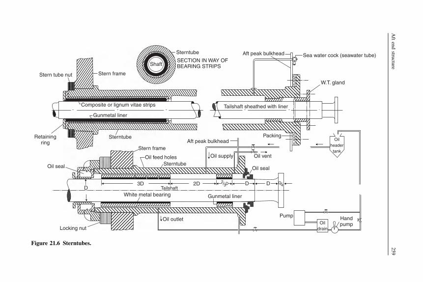
Sterntube
Shaft
Stern tube nut Stern frame
Composite or lignum vitae strips Tailshaft sheathed with liner
PackingOil
headertank
Gunmetal liner
Sterntube
Sterntube
Aft peak bulkheadStern frame
Oil feed holes
Oil seal
D3D 2D DD DD2
3 4Tailshaft
PumpOil outlet
Locking nut
Gunmetal liner
Oil seal
Oil ventOil supply
White metal bearing
HandpumpOil
drain
Aft peak bulkhead
W.T. gland
Sea water cock (seawater tube)
Retainingring
SECTION IN WAY OFBEARING STRIPS
Figure 21.6 Sterntubes.
Aftendstru
cture
259

for some distance. Access from inside the hull is thus provided to the shaft overa great proportion of its length, and it is afforded greater protection. Many large linershaving high speeds are shown to have benefitted by a decrease in resistance whenbossings have been fitted rather than ‘A’ brackets. However, large liners of morerecent design have in some instances had extended shafts solely supported by ‘A’brackets of improved design.
Construction of bossing and ‘A’ brackets
The shaped frames and plating forming the bossing terminate in a casting known asthe ‘spectacle frame’, which provides the aftermost bearing for the shaft. This may becast or fabricated and forms a box-like section athwartships that is rigidly connectedto heavy plate floors. The arms carrying the shafts extend from this section, whichmay be split in two or more parts in some instances to aid alignment when it is erected(see Figure 21.7).
‘A’ brackets may be cast or fabricated, particular attention being paid to the strutsection to avoid increases in resistance and cavitation. The connections to the mainhull are of particular importance since considerable rigidity of the structure isrequired. Although on smaller vessels the upper palms may simply be welded toa reinforcing pad at the shell, on larger vessels the upper ends of the struts enter themain hull and are connected to a heavy floor with additional local stiffening(Figure 21.7).
Propellers
Ship propellers may have from three to six similar blades, the number beingconsistent with the design requirements. It is important that the propeller isadequately immersed at the service drafts and that there are good clearances betweenits working diameter and the surrounding hull structure. The bore of the propeller bossis tapered to fit the tail shaft and the propeller may be keyed onto this shaft; a largelocking nut is then fitted to secure the propeller on the shaft. For securing the propellera patent nut with a built-in hydraulic jack providing a frictional grip between thepropeller and tail shaft is available. This ‘pilgrim nut’ may also be used with keylessbore propellers. A fairing cone is provided to cover the securing nut.
Controllable pitch propellers
These are propellers in which the blades are separately mounted on the boss, and inwhich the pitch of the blades can be changed, and even reversed, by means ofa mechanism in the boss, whilst the propeller is running. The pitch is mechanically orelectromechanically adjusted to allow the engines’ full power to be absorbed underdifferent conditions of operation. It is incorrect to refer to such a propeller asa variable pitch propeller since virtually all merchant ship propellers have a fixedpitch variation from blade root to blade tip.
260 Ship Construction

lap
Plate
CAST SPECTACLEFRAME
SECTIONLOOKING AFT
Floor
Stringer
Strut
Floor
Ship’s
‘A’ – BRACKET
Propeller shaft
FRAME IN WAY OF BOSSING Inserted frame
Casting boltedat center line
PLAN
Floor
Plate bossing
Horizontal web
Webframe
Figure 21.7 Bossings and ‘A’ brackets.
Aftendstru
cture
261

Propellers of this type are often found on diesel-engined tugs and trawlers where thepropeller pitch may be changed to allow the full torque to be absorbed under towing ortrawling conditions, and also when the vessel is running freely at full revolutions anda higher speed. It is possible to reverse the pitch in order to stop the vessel rapidly andgo astern, with the propeller shaft and propeller still rotating in the one direction.
Large controllable pitch propellers have been fitted to large diesel-driven bulkcarriers in recent years.
Shrouded propellers
To increase the thrust provided by a propeller of given diameter at low speeds andhigh slips it may be enclosed in a fixed nozzle. Single-screw tugs and trawlers areoften fitted with the fixed patent ‘Kort nozzle’ where under a heavy tow the propelleris working at a high slip. This nozzle has a reducing diameter aft and is relatively shortin relation to the diameter, to avoid increasing the directional stability, thus makingsteering difficult.
When running freely the slip is much lower, and it might appear that there waslittle advantage in fitting a shrouded propeller. However, serious consideration hasbeen given to fitting shrouded propellers on very large single-screw ships where thereis a problem of absorbing the large powers on the limited diameter.
Some ships are fitted with a steering nozzle that not only fulfills the purposes ofa fixed nozzle but has a turning stock and fin, and pivots about the ship’s longitudinalaxis can be used to steer the ship.
The fabricated construction is similar for both the fixed and steering nozzles, and isshown in Figure 21.8 for a nozzle of 2.5–3 meters in diameter. The inner plating of thenozzle has a heavier ‘shroud’ plate in way of the propeller tips and this is carried somedistance fore and aft of this position. At this diameter the nozzle section has two fullring webs and a half-depth ring web supporting the inner and outer plating.
Electric podded propulsors
In recent years a number of large cruise ships have been fitted with electric poddedpropulsors. Pod propulsion has also been considered for large container ships and fastro-ro passenger ships.
The advantages of electric podded propulsors are:
1. Lengths of propeller shafting within the hull are eliminated, thus providing more revenueearning space.
2. The hull form can be designed for minimum resistance.3. The thrusters provide good propeller clearances and can be aligned with the local waterflow
to provide a clean flow of water to the pulling propeller.4. Lower noise and vibrations are claimed but it is reported that with some installations this has
not always been the case.5. There is improved maneuverability, which is a major advantage for cruise ships visiting
a number of ports.
262 Ship Construction

Flare plating
Leading edge bar
Trailingedge bar
Cone plating
Ring web
Fore and Aftw seb
TRANSVERSE SECTION FORE AND AFT SECTIONAT CENTER LINE
Ring webs
Shroudplating in way ofpropeller
Flare plating
Shroudplating in way ofpropeller
Figure 21.8 Propeller nozzle.
Aftendstru
cture
263
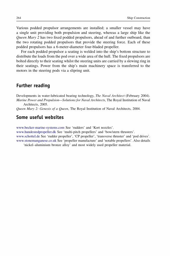
Various podded propulsor arrangements are installed; a smaller vessel may havea single unit providing both propulsion and steering, whereas a large ship like theQueen Mary 2 has two fixed podded propulsors, ahead of and further outboard, thanthe two rotating podded propulsors that provide the steering force. Each of thesepodded propulsors has a 6-meter-diameter four-bladed propeller.
For each podded propulsor a seating is welded into the ship’s bottom structure todistribute the loads from the pod over a wide area of the hull. The fixed propulsors arebolted directly to their seating whilst the steering units are carried by a slewing ring intheir seatings. Power from the ship’s main machinery space is transferred to themotors in the steering pods via a slipring unit.
Further reading
Developments in water-lubricated bearing technology, The Naval Architect (February 2004).Marine Power and Propulsion—Solutions for Naval Architects, The Royal Institution of Naval
Architects, 2005.Queen Mary 2: Genesis of a Queen, The Royal Institution of Naval Architects, 2004.
Some useful websites
www.becker-marine-systems.com See ‘rudders’ and ‘Kort nozzles’.www.hundestedpropeller.dk See ‘multi-pitch propellers’ and ‘bow/stern thrusters’.www.schottel.de See ‘rudder propeller’, ‘CP propeller’, ‘transverse thruster’ and ‘pod drives’.www.stonemanganese.co.uk See ‘propeller manufacture’ and ‘notable propellers’. Also details
‘nickel–aluminium bronze alloy’ and most widely used propeller material.
264 Ship Construction

22 Tanker construction
Chapter OutlineOil tankers 265Materials for tanker construction 267
Mild steel 267Higher tensile steel 267
Construction in tank spaces 268Longitudinal framing 269Floors and transverses 269Bottom and deck girders 269
Bulkheads 271Hatchways 271Testing tanks 272Fore end structure 272
Deep tank 272Forepeak 273Ice strengthening 273
After end structure 273Superstructures 273Floating production, storage, and offloading vessels 274Chemical tankers 276Further reading 277Some useful websites 277
Ships designed specifically to carry bulk liquid cargoes are generally referred to astankers. Tankers are commonly associated with the carriage of oil, but a wide varietyof liquids are carried in smaller tank vessels and there are a considerable number oflarger tank vessels dedicated to carrying chemicals in bulk.
Oil tankers
Small tankers not exceeding 75 meters in length, involved principally in the coastaltrade, have a single longitudinal bulkhead on the center line providing two athwart-ships tanks. The machinery is aft, and an expansion trunk, if fitted, is on the center linein way of the tank spaces (see Figure 22.1).
This chapter is concerned with the construction of the larger ocean-going type,which may be considered in two classes. There are those ships that carry refined oil
Ship Construction. DOI: 10.1016/B978-0-08-097239-8.00022-2
Copyright � 2012 Elsevier Ltd. All rights reserved.

Trunk plating (11 mm)
Flat stiffenerStiffener175 mm × 8.5 mm
Frame space clear oftransverse Stringer
Deck and trunklongitudinals200 mm × 12.5 mm
175 mm × 8.5 mm
Bracket
Stringer
Longitudinalbulkhead
Deck plating (11 mm)
Sheerstrake 1500 mm × 12.5 mm
Side shell (10.5 mm)
Stringer
Frame space in way oftransverse
Bottom plating (11 mm)Bottom longitudinals 250 mm × 12 mm Keel plate 1075 mm × 16.5 mm
BracketDocking bracket
Side frame
Transverse
Figure 22.1 Midship section of coastal tanker of less than 5000 tonnes deadweight with trunk.
266
Ship
Constru
ction
products, and perhaps some other cargoes like molasses, which tend to be in thesmaller 12,000–50,000 tonnes deadweight range. Then there are the crude oil carriersthat extend to the 500,000 tonnes deadweight range. The former vessels, the smallerof which may have a single center-line longitudinal bulkhead (see Figure 22.4), havea greater number of tanks, and more complicated pumping arrangements that permitthe carriage of a number of different products on a single voyage.
Both types of ship have traditionally been single flush deck ships with longitudinalbulkheads and a structurewithin the tank spaces consisting of a grillage of longitudinaland transverse members. The structural arrangement over the cargo tank length isdictated by the requirements of theMARPOL convention (see Chapter 29). Since 1980new crude tankers of 20,000 tonnes deadweight or more and new products carriers of30,000 tonnes deadweight ormorewere required to be providedwith segregated ballasttanks (SBTs), the capacity of the SBTs being so determined that the ship could operatesafely on ballast voyages without recourse to the use of cargo tanks for ballast water.These SBTs were to be located within the cargo tank length and arranged to providea measure of protection against oil outflow in the event of grounding and or collision.The protective location of these tanks had the effect of providing full or partial doublebottoms and/or side tanks in way of the cargo tank space. Subsequent amendments toMARPOL required every tanker of 5000 tonnes deadweight or more that commencedconstruction after 1993 to have the entire cargo tank length protected by ballast tanks orspaces other than cargo and fuel oil tanks, or other provisions offering equivalentprotection against oil pollution. As we have seen in Chapter 3 double hulls have beenrequired for Category 1 oil tankers from 2005 and for Category 2 and 3 oil tankers from2010. (There is, however, provision for the flag state to permit some oil tankers ofCategory 2 and 3 to operate beyond these dates to 2015 or until their 25th anniversary,but port states may deny such ships entry to their ports).
Materials for tanker construction
Mild steel is used throughout the structure, but higher tensile steels may also beintroduced in the more highly stressed regions of the larger vessels.
Mild steel
As with dry cargo ships it is a requirement that Grade B, D, and E steels be used for theheavier plating of the main hull strength members where the greatest stresses arise intankers. These requirements are the same as those indicated in Table 17.1. Grade Eplates, which we have equated with the ‘crack arrester strake’ concept (see Chapter 8),will be seen to be required over the midship region in ships exceeding 250 meters inlength and are also required as shown in Table 22.1.
Higher tensile steel
Higher tensile steels are often used for the deck and bottom regions of the largertankers, Grades DH and EH being used for the heavier plating. As indicated in
Tanker construction 267

Chapter 5, the use of higher tensile steel leads to a reduction in the scantlings of thesestructural items with advantages both for the shipbuilder and owner. There is someconcern that the thinner material may lead to problems if corrosion occurs, and thatthe thinner plate may also lead to additional fatigue problems due to excess movementof the structure under the forces encountered. The extent of this plating and sectionmaterial is indicated in Figure 22.2.
Construction in tank spaces
Today’s ocean-going crude oil tankers are generally large and in way of the tankspaces have a longitudinally framed double bottom supported by transverse floorsand a longitudinally framed deck supported by deck transverses. The longitudinally
Table 22.1 Use of Grade E steel in tankers
Location Thickness
Stringer plate, sheerstrake, rounded gunwale Greater than 15 mmBilge strake, deck strake in way of longitudinalbulkhead
Greater than 25 mm
Main deck plating, bottom plating, keel, upperstrake of longitudinal bulkhead
Greater than 40 mm
Stringer
Transverseweb
Deck-transverseweb
CENTRETANK
Length B.PBeam mld.Depth mld.
315 m58 m30.4 m
Platebracket
Inner bottom
Intermediatestringer
WING TANK
Longitudinalbulkhead
Inner hull
Floor3.5 m
3 m ‘DH’
‘EH’ ‘DH’ ‘DH’‘EH’‘EH’
‘EH’‘DH’
‘EH’
Figure 22.2 Double-hull oil tanker.
268 Ship Construction
framed side shell, inner hull, and longitudinal bulkheads are all supported bytransverse webs aligned with the transverse floors and deck transverses (seeFigure 22.3).
Longitudinal framing
Deck and bottom longitudinals have the greatest scantlings since they are stiffeningthe more highly stressed flanges of the hull girder. At the side shell the upperlongitudinals have the least scantlings, and a uniform increase in size occurs down theside shell until the bilge is reached. The bilge longitudinal size then approaches that ofthe bottom shell. For products carriers the deck longitudinals may be fitted above thedeck to provide a flush internal tank surface for cleaning (see Figure 22.4). Animportant feature of the longitudinal framing is that continuity of strength is main-tained, particularly at the bulkheads forming the ends of the tanks. This feature isincreasingly important as the ship length is extended, the bottom and deck longitu-dinals being continuous through the bulkhead where the ship length is excessive,unless an alternative arrangement is permitted by the classification society (seeFigure 22.3). Higher tensile steel longitudinals are to be continuous irrespective ofship length.
The longitudinals can be offset bulb plates that may be built up to give therequired scantling on large ships. It is not, however, uncommon to find on manytankers specially fabricated tee longitudinals having a web and symmetrical flatplate flange.
Floors and transverses
To support the bottom and inner bottom longitudinals solid plate floors are fitted.Stiffened transverse plate webs support the side shell and inner shell longitudinals,deck longitudinals, and longitudinal bulkhead stiffening. In way of the center tanka bracketed deck transverse supports the deck longitudinals and large platebrackets are fitted between the longitudinal bulkheads and inner bottom (seeFigure 22.2).
Transverses are as a rule built of a plate web and heavier flat face bar, thedepth being adequate to allow sufficient material abreast the slots through whichthe longitudinals pass. Within the double-hull side space they form a solid web andare supported by horizontal stringers (see Figure 22.2). In the wing tankspace they support the deck longitudinals and fore and aft bulkhead longitudinals,and in turn are supported by a mid-height longitudinal plate stringer (seeFigure 22.2).
Bottom and deck girders
A center-line girder is required in the double-bottom space, which with the heavy keelplate constitutes the immediate structure through which docking loads are transmittedwhen the vessel is placed on the keel blocks.
Tanker construction 269

De ck
Deck centre girder
Fla
t stif
fene
r F
lat s
tiffe
ner
Fla
t stif
fene
r
Tra
nsve
rse
Tra
nsve
rse
Doc
king
bra
cket
Doc
king
bra
cket
Doc
king
bra
cket
Flat stiffeners
Fla
t stif
fene
r
F la t s t
iff e n e
r
Flat
stif
f ene
r
Tra
nsve
rse
Tra
nsve
rse
O. T. transverse bulkhead
Centre lin e bulkhead web
O. T. transverse bulkhead ELEVATION AT CENTRE
LINE OF TANK
Longtl.
Longtl.
Longtl.
Gusset plate
Longitudinal
ELEVATION
O.T.bulkhead
O. T. bu lkhead
Gusset plate
PLAN
CONTINUITY OF LONGITUDINALS THRO’ TRANSVERSE BULKHEADS
O.T.bulkhead
Plate bracket welded through bulkhead
Tripping bracket Longitudinal
Alternate arrangement
Bottom Centre girder
Figure 22.3 Longitudinal framing of oil tankers.
270
Ship
Constru
ction

Bulkheads
Bulkhead spacing throughout the cargo tank space is determined by the permissiblelength of cargo tanks. MARPOL requires that the length of each cargo tank shallnot exceed the greater of 10 meters or a length expressed as a percentage of theship’s length that is dependent on the number of longitudinal bulkheads fitted andthe minimum distance from the ship’s side of the outer longitudinal bulkhead.Tankers with two or more longitudinal bulkheads may have wing and center tanklengths up to 20% of the ship’s length. Lloyd’s Register require the disposition oftransverse bulkheads to comply with the stipulations given in Table 18.1, asapplicable to ships with machinery aft. Cofferdams, which may be formed with twoadjacent oiltight transverse bulkheads at least 760 mm apart, are required at theends of the cargo space. However, in many cases a pump room is fitted at the afterend of the cargo space (also forward on some products carriers) and a ballast tankis fitted at the forward end, each of these compartments being accepted in lieu ofa cofferdam. A cofferdam is also provided between any accommodation and oilcargo tanks.
Construction of the transverse bulkheads is similar to that in other ships, thebulkhead being oiltight. Vertical stiffeners are fitted, or corrugated plating is providedwith the corrugations running either vertically or horizontally. Horizontal stringerssupport the vertical stiffeners and corrugations, and vertical webs support any hori-zontal corrugations. Further support is provided by the vertical center-line web, whichis as a rule deeper on one side of the bulkhead than on the other, unless the tank is verylong and the web may then be symmetrical either side of the bulkhead.
Longitudinal bulkheads, which are oiltight, may be conventionally stiffened ormay be corrugated with the corrugations running horizontally. Vertical corrugatedcenter-line bulkheads may be fitted. Conventional stiffening is arranged verticallywhere the side framing is vertical and arranged longitudinally when the side islongitudinally framed. Vertical webs are fitted to the longitudinal bulkhead when thisis corrugated or longitudinally framed. Corrugated longitudinal bulkheads are onlypermitted in ships of less than 200 m in length.
Hatchways
Oiltight hatchways provide access to the tank spaces at the exposed deck. Theopenings for these are kept as small as possible, and the corners are well rounded,circular openings being not uncommon. Coamings provided for the openings shouldbe of steel and at least 600 mm high, and suitably fastened steel or other approvedmaterial covers are fitted. Patent oiltight hatches are available and approved with bothsteel- and fiber-reinforced plastic covers.
Access to any cofferdams and water ballast tanks may be by similar hatches in thedeck, or alternatively a watertight manhole may be fitted with a cover of suitablethickness. Other openings are provided in the deck for ullage plugs and tank cleaning,these being on the open deck, and not within enclosed deck spaces.
Tanker construction 271

Testing tanks
Each cargo tank and cofferdam may be tested separately when complete by filling thetank with water to a head 2.45 m above the highest point of the tank excludingthe hatchways, and by filling the cofferdam to the top of the hatch. Water testing onthe building berth or dry dock may be undesirable owing to the size of flooded tanks,which gives rise to large stresses on the supporting material and structure. Testingafloat is therefore permitted, each tank being filled separately until about half thetanks are full, when the bottom and lower side shell in the empty tanks are examined.Water is then transferred to the empty tanks, and the remainder of the bottom and sideshell is inspected. This testing may take place after the application of protectivecoatings, provided that welds have been carefully examined beforehand.
In practice, a combination of a structural water test and air leak test is often used.The air leak test is carried out on the building berth, the tanks being subject to an airpressure similar to that required for testing double-bottom tanks. Awater pressure testis carried out on one center tank and two wing tanks selected by the surveyors.
Clean water ballast tanks are tested in the same manner as the cargo tanks, butbunkers and deep tank test requirements are similar to those in dry cargo ships, i.e.a head of water 2.45 m above the crown of the tank is applied. Any bulkhead notforming a tank boundary is hose tested.
Fore end structure
Forward of the tank space deep tanks may be fitted. Framing throughout this spaceand the forepeak may be transverse, longitudinal, or a combination of both.
Deep tank
If transverse framing is adopted, forward floors are fitted at every frame space inconjunction with a center-line girder or center-line bulkhead and intercostal sidegirders not more than three times the transverse frame spacing apart. If longitudinalbulkheads are fitted port and starboard in the cargo tanks, these may be extended tothe fore side of the deep tank in lieu of a center-line bulkhead. Above the floors thetransverse frames are supported by stringers spaced not more than 5 m apart, whichare either supported by web frames connected to deep beams to form a vertical ringframe, or connected to longitudinal stringers on the transverse bulkheads to formhorizontal ring frames. Alternatively, in narrow tanks perforated flats may be fitted at5 m spacings.
Longitudinally framed deep tanks are supported by side transverses five framespaces apart. Where the depth of the tank exceeds 16 m the side transverses, and theweb frames in a transversely framed tank, either have one or more deep stringersfitted, cross ties, or perforated flats with deep beams in way of the transverses or webs.
A longitudinal bulkhead generally must be provided if the tank width exceeds 50%of the ship’s beam and may solely be a wash bulkhead on the center line. Where the
272 Ship Construction
breadth of tank exceeds 70% of the ship’s beam, at least one solid bulkhead on thecenter line is recommended.
Forepeak
A transversely framed forepeak has a similar construction to that of a conventionalcargo ship and includes the usual panting arrangements (see Chapter 20). If theforepeak is longitudinally framed the side transverses have a maximum spacing ofbetween 2.5 and 3.5 m depending on the length of ship, and are connected totransverses arranged under the decks in line with the side transverses. Forecastleshave web frames to support any longitudinal side framing, and the forecastle deckmay be supported by pillars at its center line.
Ice strengthening
With the growing export of oil from Russia an increasing number of new tankers arebeing provided with ice strengthening forward (see Chapter 17) so that they can tradeto parts of the Baltic Sea that can be frozen in winter. These include several 20,000tonne deadweight ice-breaking oil tankers.
After end structure
The machinery is arranged aft in ocean-going tankers, and a transversely frameddouble-bottom structure is adopted in way of the machinery space. Constructionaldetails of this double bottom are similar to those of the conventional dry cargo ship,with floors at each frame space, additional side girders, and the engine seating integralwith the bottom stiffening members.
Transverse or longitudinal side and deck framing may be adopted in way of theengine room and aft of this space. If transversely framed, web frames are fitted notmore than five frame spaces apart below the lowest deck and may be supported byside stringers. The web frames may be extended into the poop, and where an all-houses aft arrangement is adopted they may also extend into the superstructure.Similar transverse webs are introduced to support any longitudinal framing adopted ina machinery space. Transverse webs have the same spacing as web frames except intween decks above the aft peak, where the maximum spacing is four frame spaces.
The aft peak and stern construction follows that of other merchant ship types,a center-line bulkhead being provided in the aft peak. Any ice strengthening is similarto that required in other ships (see Chapter 17).
Superstructures
To permit the assignment of deeper freeboards for oil tankers, the conditions ofassignment of load line (see Chapter 31) stipulate the requirements for protective
Tanker construction 273

housings enclosing openings in the freeboard and other decks. They also requireprovision of a forecastle covering 7% of the ship’s length forward.
Structurally, the houses are similar to those of other vessels, special attention beingpaid to the discontinuities in way of breaks at the ends of the houses. Particularattention must be paid to any endings in the midship length of the hull. As themachinery is aft the poop front merits special attention, and is in fact structurallysimilar to the bridge front, since its integrity is essential.
A particular feature of the tanker with its lower freeboard is the requirement for anaccess gangway at the level of the first tier of superstructure between accommodationspaces. This is still often found on vessels with all accommodation aft, although theregulations would permit a rail or similar safety arrangement at the deck level. Theprovision of a gangway in the latter case is at the owner’s wish, and is an added safetyfactor at greater initial cost, requiring additional maintenance. Another feature is theabsence of bulwarks on the main decks, the regulations requiring the provision ofopen rails over at least half the length of the wells, which are often awash in heavyweather.
Floating production, storage, and offloading vessels
Floating production, storage, and offloading vessels (FPSOs) and floating storageunits (FSUs) are now a common feature of offshore oil installations.
A typical FSU is of 100,000 tons deadweight with a storage capacity of 112,000cubic meters representing 10 days production. Crude oil from a floating productionunit (FPU) is transferred to the FSU, where it is loaded via a submerged turret loading(STL) system. From the FSU the crude oil is transferred to shore by shuttle tankers,which are loaded by flexible hoses from the stern of the FSU. An FPSO combines thefunctions of the FPU and FSU in a single floating unit.
Many oil tankers, more recently those with a single hull that are barred from sometrades, have been converted to FPSOs and FSUs, but there are also numbers of newdesign and build contracts for such vessels. The basic hull construction is similar tothat for conventional tankers but there are arrangements and structural featurespeculiar to these vessels. The vessels are moored using a turret system forward,which allows the hull to weathervane into the wind and waves to reduce dynamicloading on the hull girder. However, because the waves will be coming mainlytowards the bow for the whole of its life, the hull girder will experience greaterfatigue problems than would be the case for a conventional tanker. The conventionaltanker carries little in the way of loading on its main deck, whereas an FPSO is fittedwith a substantial oil production facility, which can weigh in excess of 20,000 tons.This loading needs to be transferred into the hull structure, which means that verticalstructural components are more complex and substantial than those of a tanker.Further, because both FSUs and FPSOs are expected to remain on station for theirlifetime and withstand arduous conditions without dry-docking, the exposed hullconstruction is generally upgraded and strengthened with increased corrosionprotection.
274 Ship Construction
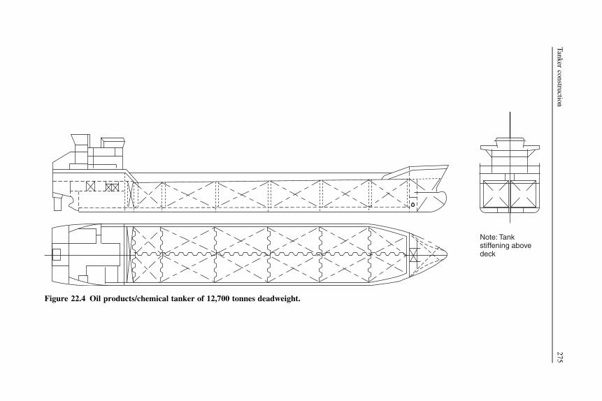
Note: Tankstiffening abovedeck
Figure 22.4 Oil products/chemical tanker of 12,700 tonnes deadweight.
Tanker
constru
ction
275

Chemical tankers
The structural configurations and arrangements of chemical tankers often are basi-cally similar to those described for oil tankers, particularly where the chemicalproduct is not required to be carried in an independent tank. For some cargoes tanksconstructed of stainless steel are preferred. Where the chemical product is required tobe carried in an independent tank the structure and arrangements may be similar toships carrying liquefied gases described in Chapter 23.
Regardless of size, ships built or converted on or after 1 July 1986 andengaged in the carriage of bulk cargoes of dangerous or noxious liquidchemical substances, other than petroleum or similar flammable products, arerequired to comply with the International Code for the Construction and Equip-ment of Ships Carrying Dangerous Chemicals in Bulk (IBC Code). Such shipsbuilt or converted before that date are to comply with the earlier Code for theConstruction and Equipment of Ships Carrying Dangerous Chemicals in Bulk(BCH Code). Ships that comply with these requirements are issued with an‘International Certificate of Fitness for the Carriage of Dangerous Chemicalsin Bulk’.
Under the IBC Code chemical tankers are designed and constructed to one of threespecified standards. A type 1 ship is a chemical tanker intended for the transportationof products considered to present the greatest overall hazard. It should be capable ofsurviving the most severe standard of damage and its cargo tanks should be located atthe maximum prescribed distance inboard from the shell plating. Type 2 and 3 shipscarry products of progressively lesser hazards. Where a ship is intended to carrya range of products it is assigned the standard applicable to the product having themost stringent ship type requirement.
The IBC Code also defines cargo tank types. Tank type 1 is an independent tankthat is not contiguous with, or part of, the hull structure. Tank type 2 is an integraltank, i.e. it is part of the ship’s hull structure. A gravity tank (G) is an independent orintegral tank that has a design pressure of not more than 0.7 bar gage at the top of thetank. A pressure tank (P) is an independent tank that has a design pressure of morethan 0.7 bar gage.
The IBC Code specifies for each individual product to be carried the ship type andrequired tank type, e.g. sulfuric acid—ship type 3—tank type 2G.
Also, requirements for the materials of construction, freeboard, stability, generalarrangement, piping arrangements, electrical and environmental arrangements, tankventing and gas freeing, fire protection, etc. of chemical tankers are covered by theIBC Code.
Figure 22.4 shows a 130 m LOA type II oil products/chemical tanker of 12,700tonnes deadweight. The 130 meter length overall by 20 meter breadth by 9.75 meterdepth vessel has 12 cargo tanks, equipped to carry six different types or grades ofcargo simultaneously. Each tank has a deepwell pump rated at 300 cubic meters perhour and the ship’s maximum discharge rate is 1800 cubic meters per hour with sixlines working at the same time.
276 Ship Construction

Further reading
Code for the Construction and Equipment of Ships Carrying Dangerous Chemicals in Bulk(BCH Code). IMO publication (IB772E), 2005 edition.
Common Structural Rules For Double Hull Oil Tankers. IACS publication.Design and operation of double hull tankers. Conference Proceedings and Papers, Royal
Institution of Naval Architects Publications, 2004.International Code for the Construction and Equipment of Ships Carrying Dangerous
Chemicals in Bulk (IBC Code). IMO publication (IMO-100E), 1998 edition.MARPOL 73/78 Consolidated Edition, IMO publication (IMO 1B520E), 2002.MARPOL 2005, Amendments 2005. IMO publication (IMO 1525E)
Some useful websites
www.intertanko.com Current regulatory and technical issues relating to oil and chemicaltankers.
www.imo.org ‘Safety’; see ‘tanker safety’.www.iacs.org.uk See ‘Common structural rules for double hull oil tankers’.
Tanker construction 277
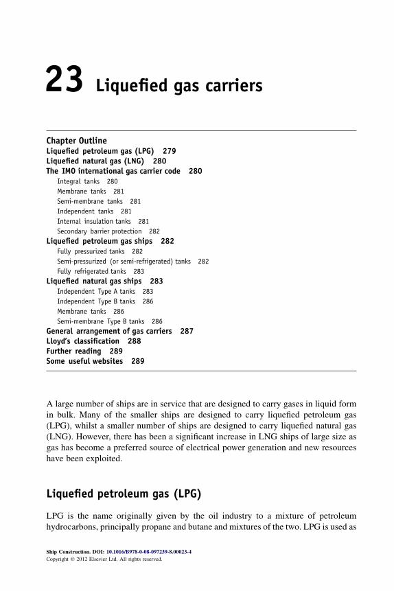
23 Liquefied gas carriers
Chapter OutlineLiquefied petroleum gas (LPG) 279Liquefied natural gas (LNG) 280The IMO international gas carrier code 280
Integral tanks 280Membrane tanks 281Semi-membrane tanks 281Independent tanks 281Internal insulation tanks 281Secondary barrier protection 282
Liquefied petroleum gas ships 282Fully pressurized tanks 282Semi-pressurized (or semi-refrigerated) tanks 282Fully refrigerated tanks 283
Liquefied natural gas ships 283Independent Type A tanks 283Independent Type B tanks 286Membrane tanks 286Semi-membrane Type B tanks 286
General arrangement of gas carriers 287Lloyd’s classification 288Further reading 289Some useful websites 289
A large number of ships are in service that are designed to carry gases in liquid formin bulk. Many of the smaller ships are designed to carry liquefied petroleum gas(LPG), whilst a smaller number of ships are designed to carry liquefied natural gas(LNG). However, there has been a significant increase in LNG ships of large size asgas has become a preferred source of electrical power generation and new resourceshave been exploited.
Liquefied petroleum gas (LPG)
LPG is the name originally given by the oil industry to a mixture of petroleumhydrocarbons, principally propane and butane and mixtures of the two. LPG is used as
Ship Construction. DOI: 10.1016/B978-0-08-097239-8.00023-4
Copyright � 2012 Elsevier Ltd. All rights reserved.

a clean fuel for domestic and industrial purposes. These gases may be converted to theliquid form and transported in one of three conditions:
1. Solely under pressure at ambient temperature2. Fully refrigerated at their boiling point (�30 to �48 �C)3. Semi-refrigerated at reduced temperature and elevated pressure.
A number of other gases with similar physical properties, such as ammonia,propylene, and ethylene, are commonly shipped on LPG carriers. These gases areliquefied and transported in the same conditions as LPG except ethylene, which boilsat a much lower temperature (�104 �C) and which is therefore carried in the fullyrefrigerated or semi-refrigerated condition.
Liquefied natural gas (LNG)
LNG is natural gas from which most of the impurities such as sulfur and carbondioxide have been removed. It is cooled to or near its boiling point of �165 �C at ornear atmospheric pressure and is transported in this form as predominantly liquidmethane. Methane has a critical pressure of 45.6 kg/cm2 at a critical temperature of�82.5 �C, i.e. the pressure and temperature above which liquification cannot occur, sothat methane can only be liquefied by pressure at very low temperatures.
The IMO international gas carrier code
In 1975 the Ninth Assembly of the IMO adopted the Code for the Construction andEquipment of Ships Carrying Liquefied Gases in Bulk, A.328 (IX), which providesinternational standards for ships that transport liquefied gases in bulk. It becamemandatory in 1986 and is generally referred to as the IMO International Gas CarrierCode. The requirements of this code are incorporated in the rules for ships carryingliquefied gases published by Lloyd’s Register and other classification societies.
The code covers damage limitations to cargo tanks and ship survival in the event ofcollision or grounding, ship arrangements for safety, cargo containment and handling,materials of construction, environmental controls, fire protection, use of cargo as fuel,etc. Of particular interest in the context of ship construction is the section on cargocontainment, which defines the basic cargo container types and indicates ifa secondary barrier is required, i.e. a lining outside the cargo containment thatprotects the ship’s hull structure from the embrittling effect of the low temperatureshould cargo leak from the primary tank structure. The cargo containment types aredescribed below.
Integral tanks
These tanks form a structural part of the ship’s hull and are influenced in the samemanner and by the same loads that stress the adjacent hull structure. These are used
280 Ship Construction

for the carriage of LPG at or near atmospheric conditions, butane for example, whereno provision for thermal expansion and contraction of the tank is necessary.
Membrane tanks
These are non-self-supporting tanks consisting of a thin layer (membrane) supportedthrough insulation by the adjacent hull structure. The membrane is designed in sucha way that thermal and other expansion or contraction is compensated for withoutundue stressing of the membrane. Membrane tanks are primarily used for LNGcargoes (see Figure 23.4).
Semi-membrane tanks
These are non-self-supporting tanks in the load condition. The flat portions of the tankare supported, transferring the weight and dynamic forces through the hull, but therounded corners and edges are not supported so that tank expansion and contraction isaccommodated. Such tanks were developed for the carriage of LNG, but have beenused for a few LPG ships.
Independent tanks
These are self-supporting and independent of the hull. There are three types:
l ‘Type A’, which are designed primarily using standard traditional methods of ship structuralanalysis. LPG at or near atmospheric pressure or LNG may be carried in such tanks (seeFigure 23.2).
l ‘Type B’, which are designed using more sophisticated analytical tools and methods todetermine stress levels, fatigue life, and crack propagation characteristics. The overalldesign concept of these tanks is based on the so-called ‘crack detection before failureprinciple’, which permits their use with a reduced secondary barrier (see Figure 23.3). LNGis normally carried in such tanks.
l ‘Type C’, which are designed as pressure vessels, the dominant design criteria being thevapor pressure. Normally used for LPG and occasionally ethylene.
Internal insulation tanks
These are non-self-supporting and consist of thermal insulation materials, the innersurface of which is exposed to the cargo supported by the adjacent inner hull or anindependent tank. There are two types:
l ‘Type 1’, where the insulation or combination of insulation and one or more liners act onlyas the primary barrier. The inner hull or independent tank forms the secondary barrier.
l ‘Type 2’, where the insulation or combination of insulation and one or more liners act asboth the primary and secondary barriers and are clearly distinguishable as such.
The liners on their own do not act as liquid barriers and therefore differ frommembranes. These tanks are a later addition to the Code and Type 1 is known to havebeen used for the carriage of LPG.
Liquefied gas carriers 281

Secondary barrier protection
The requirements for secondary barrier protection are given in Table 23.1.
Liquefied petroleum gas ships
Ships carrying LPG are categorized by their cargo containment system. Figure 23.1shows the three types discussed below.
Fully pressurized tanks
The capacity of fully pressurized ships is usually less than 2000 m3 of propane,butane, or anhydrous ammonia carried in two to six uninsulated horizontal cylindricalpressure vessels arranged below or partly below deck. These independent tanks ofType C are normally designed for working pressures up to 17.5 kg/cm2, whichcorresponds to the vapor pressure of propane at 45 �C, the maximum ambienttemperature the vessel is likely to operate in. The tanks can be constructed fromordinary grades of steel, are mounted in cradle-shaped foundations, and if below deckare fitted with domes protruding through the deck to which are fitted all connections.Wash bulkheads are fitted in very long tanks. The shape of the tanks generallyprevents good utilization of the underdeck space.
Semi-pressurized (or semi-refrigerated) tanks
The capacity of semi-pressurized ships ranges up to about 5000 m3, the cargoescarried being similar to fully pressurized ships. The independent Type C tanks aregenerally constructed of ordinary grades of steel suitable for a temperature of �5 �C
Table 23.1 Requirements for secondary barrier protection
Cargo temperature at atmospheric pressure
�10 �C and aboveBelow �10 �Cdown to �55 �C Below �55 �C
Basic tank typeNo secondarybarrier required
Hull may act assecondary barrier
Separate secondary barrierrequired
Integral Tank type not normally allowedMembrane Complete secondary barrierSemi-membrane Complete secondary barrierIndependentType A Complete secondary barrierType B Partial secondary barrierType C No secondary barrierInternal insulationType 1 Complete secondary barrierType 2 Complete secondary barrier
incorporated
282 Ship Construction

and are designed for a maximum pressure of about 8 kg/cm2. The outer surface of thetank is insulated and refrigeration or reliquefication plant cools the cargo andmaintains the working pressure. Cargo tanks are often horizontal cylinders mountedon two saddle supports and many designs (see Figure 23.1) incorporate bio-lobe tanksto better utilize the underdeck space and improve payload.
Fully refrigerated tanks
The capacity of fully refrigerated ships ranges from 10,000 to 100,000 m3, the smallerships in the range being multi-product carriers whilst the larger vessels tend to besingle-product carriers on a permanent route. Tanks fall almost exclusively into theprismatic, independent Type A category with tops sloped to reduce free surface andbottom corners sloped to suit the bilge structure. In most cases they are subdividedalong the center line by a liquid-tight bulkhead that extends to the underside of thedome projecting through the deck that is used for access and piping connections, etc.The tanks sit on insulated bearing blocks so that surfaces are accessible for inspectionand are located by anti-roll and pitch keys in such a manner that expansion andcontraction can take place relative to the ships structure. Antiflotation chocks areprovided to prevent the tank floating off the bearings if the hold were flooded. Tanksare constructed of a notch ductile steel for the normal minimum operating temper-ature of �43 �C, the boiling point of propane.
The ship has a double hull extending over the bottom and bilge area, the secondarybarrier being provided by low-temperature (notch ductile) steel at the inner bottom,sloping bilge tank, part side shell, and sloping bottom of topside tank. Transversebulkheads may be single- or double-plate (cofferdam) type between cargo holds.Insulation can be either on the tank or the secondary barrier for this type of ship.
Liquefied natural gas ships
There are over 20 approved patent designs of containment vessel for LNG ships, themajority of which fall into the membrane or independent tank categories. Those typesthat have been or are more commonly found in service are described below. A featureof LNG ships is their double-hull construction, within which are fitted the cargo tanksand the secondary barrier system.
At the beginning of 2011, some 350 large LNG ships were trading; older shipshave independent Type B tanks of the Kvaerner-Moss design with most being of themembrane type. The GAZ Transport membrane system is twice as prevalent as othermembrane systems.
Independent Type A tanks
Early LNG ships such as the ‘Methane Princess’ and ‘Methane Progress’ werefitted with self-supporting tanks of aluminum alloy having center-line bulkheads(see Figure 23.2). The balsa wood insulation system was attached to the inner hull
Liquefied gas carriers 283
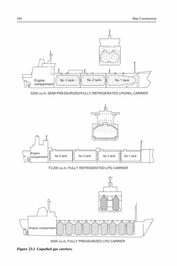
Enginecompartment
Enginecompartment
Engine compartment
4000 cu.m. FULLY PRESSURIZED LPG CARRIER
73,200 cu.m. FULLY REFRIGERATED LPG CARRIER
5200 cu.m. SEMI-PRESSURIZED/FULLY REFRIGERATED LPG/NH CARRIER3
No 4 tank No 3 tank No 2 tank No 1 tank
No 3 tank No 2 tank No 1 tank
Figure 23.1 Liquefied gas carriers.
284 Ship Construction

Midship section
1239 8 7 456
PLAN AT SECOND DECK
9 8 7 6 5 4 3 2 1MachineryForepeak
F.O.tanks
Nitrogentank
Cargo tanks
W.B.
PROFILE
PVC foam seal betweenbalsa panels
Aluminum cargotank
Plywood facedbalsa panels
Glass fiber
Inert space
Timberfurringstrip
Steelsection
Glass fiber
Steel innerhull
Figure 23.2 Liquid methane carrier.
Liquefied
gas
carriers285
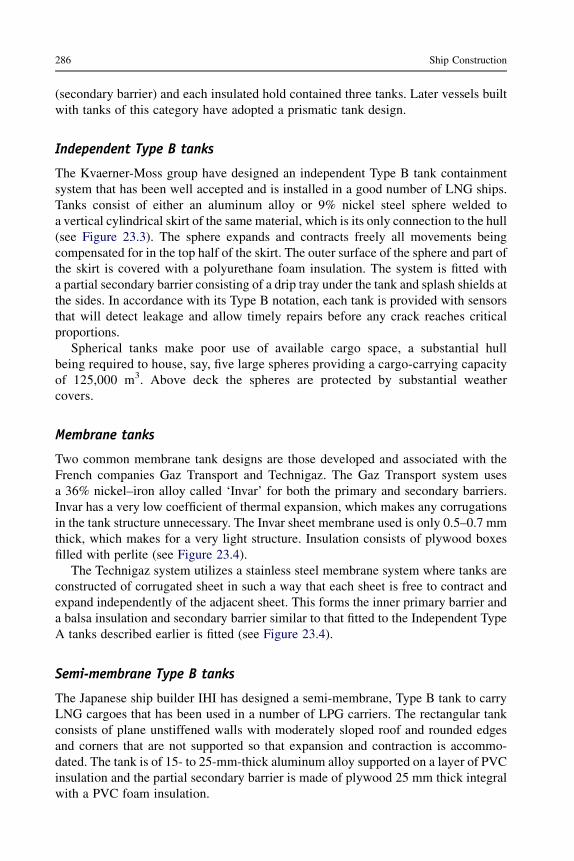
(secondary barrier) and each insulated hold contained three tanks. Later vessels builtwith tanks of this category have adopted a prismatic tank design.
Independent Type B tanks
The Kvaerner-Moss group have designed an independent Type B tank containmentsystem that has been well accepted and is installed in a good number of LNG ships.Tanks consist of either an aluminum alloy or 9% nickel steel sphere welded toa vertical cylindrical skirt of the same material, which is its only connection to the hull(see Figure 23.3). The sphere expands and contracts freely all movements beingcompensated for in the top half of the skirt. The outer surface of the sphere and part ofthe skirt is covered with a polyurethane foam insulation. The system is fitted witha partial secondary barrier consisting of a drip tray under the tank and splash shields atthe sides. In accordance with its Type B notation, each tank is provided with sensorsthat will detect leakage and allow timely repairs before any crack reaches criticalproportions.
Spherical tanks make poor use of available cargo space, a substantial hullbeing required to house, say, five large spheres providing a cargo-carrying capacityof 125,000 m3. Above deck the spheres are protected by substantial weathercovers.
Membrane tanks
Two common membrane tank designs are those developed and associated with theFrench companies Gaz Transport and Technigaz. The Gaz Transport system usesa 36% nickel–iron alloy called ‘Invar’ for both the primary and secondary barriers.Invar has a very low coefficient of thermal expansion, which makes any corrugationsin the tank structure unnecessary. The Invar sheet membrane used is only 0.5–0.7 mmthick, which makes for a very light structure. Insulation consists of plywood boxesfilled with perlite (see Figure 23.4).
The Technigaz system utilizes a stainless steel membrane system where tanks areconstructed of corrugated sheet in such a way that each sheet is free to contract andexpand independently of the adjacent sheet. This forms the inner primary barrier anda balsa insulation and secondary barrier similar to that fitted to the Independent TypeA tanks described earlier is fitted (see Figure 23.4).
Semi-membrane Type B tanks
The Japanese ship builder IHI has designed a semi-membrane, Type B tank to carryLNG cargoes that has been used in a number of LPG carriers. The rectangular tankconsists of plane unstiffened walls with moderately sloped roof and rounded edgesand corners that are not supported so that expansion and contraction is accommo-dated. The tank is of 15- to 25-mm-thick aluminum alloy supported on a layer of PVCinsulation and the partial secondary barrier is made of plywood 25 mm thick integralwith a PVC foam insulation.
286 Ship Construction

General arrangement of gas carriers
Gas carriers have a similar overall arrangement to tankers in that their machinery andaccommodation are aft and the cargo containment is spread over the rest of the ship toforward where the forecastle is fitted.
Specific gravity of LPG cargoes can vary from 0.58 to 0.97, whilst LNG ships areoften designed for a cargo specific gravity of 0.5 so that a characteristic of LNG shipsin particular and most LPG ships is their low draft and high freeboards. Water ballast
Weather protectivecover External
insulation
Verticaltubularsupport forpiping andaccess
Water Ballast
Drip tray for smallleak detection
Coldcondition
Method of absorbingexpansion/contraction
Warm condition
9% Nickelsteelequatorialring
Figure 23.3 Kvaerner-Moss spherical tank.
Liquefied gas carriers 287

cannot be carried in the cargo tanks so adequate provision is made for it within thedouble-hull spaces, double-bottom, bilge tank, and upper wing tank spaces.
The double-hull feature of LNG carriers and many LPG ships is a required safetyfeature and the tanks of LPG ships that do not have this feature are required to bea minimum distance inboard of the shell.
Fore end and aft end structure is similar to that for other ships. The cargo section istransversely or longitudinally framed, depending primarily on size, in the samemanner as other cargo ships, the inner hull receiving special consideration where it isrequired to support the containment system.
All gas ships have spaces around the tanks that are monitored for gas leaks and inmany ships these spaces are also inerted, an inert gas system being fitted aboard theship. Liquid gas cargoes are carried under positive pressure at all times so that no aircan enter the tanks and create a flammable mixture.
Liquefaction equipment is provided aboard LPG ships; ‘boil-off’ vapor from thetanks due to any heat ingress is drawn into the liquefaction plant and returned to thetank. Boil-off vapor from LNG ship tanks can be utilized as a boiler fuel in steamships, otherwise it is vented to atmosphere, although this is not permitted in manyports, and several other solutions have been developed to overcome this problem.
Lloyd’s classification
For liquefied gas ships Lloyd’s Register may assign either one of two classes, namely‘100A liquefied gas tanker’ where the vessel is designed to carry liquefied gases in
‘Invar’ primary andsecondary barriers
Plywood boxesfilled withPerlite Corrugated stainless
steelPlywoodfacing
BalsaFiberglassTECHNIGAZ
Inner hullGAZ–TRANSPORT
Figure 23.4 Membrane systems.
288 Ship Construction

bulk in integral or membrane tanks, or ‘100A1 liquefied gas carrier’ where the vesselis designed to carry liquefied gases in bulk in independent tanks. Class notations inrespect of the type of tanks, names of gases carried, maximum vapor pressure,minimum cargo temperature, etc. may be added.
Further reading
Code for the Construction and Equipment of Ships Carrying Liquefied Gases in Bulk. IMOpublication (IMO-782E), 1993.
Design and operation of gas carriers, 2004, Royal Institution of Naval Architects ConferenceProceedings.
Design and operation of gas carriers, Supplement to The Naval Architect, September 2004.Ffooks R: Natural Gas by Sea: The Development of a New Technology, ed 2. 1993, Witherby
& Co. Ltd.Gas ships—Trends and technology, The Naval Architect, 2006.Gas ships—Trends and technology, Supplement to The Naval Architect, October 2006.Harris S: Fully Refrigerated LPG Carriers. Witherby & Co. Ltd.Harper I: Future Development Options for LNG Marine Transportation, Maldon, UK.
American Institute of Chemical Engineers, Spring National Meeting, March 2002,Wavespec Limited.
International Code for the Construction and Equipment of Ships Carrying Liquefied Gases inBulk (IGC Code), 1993, IMO publication (IMO-104E).
SOLAS Consolidated Edition see Chapter VII, Part C: Construction and equipment of shipscarrying liquefied gases in bulk, 2004, IMO publication (IMO-110E).
Some useful websites
www.wavespec.com A copy of Future Development Options for LNG Marine Transportationmentioned in the list above is available from this website.
http://www.thedigitalship.com/powerpoints/norship05/lng/Jim%20MacDonald%20LR.pdf
Liquefied gas carriers 289

24 Cargo lifting arrangements
Chapter OutlineShipboard cranes 293Masts and Sampson posts 294
Mast construction and stiffening 297Derrick rigs 297
Forces in derrick rigs 300Initial tests and re-tests of derrick rigs 304
Further reading 305Some useful websites 305
The past several decades have seen many changes in cargoes and thus in cargohanding. Significant changes have been in the use of containers for mixed cargoes,replacing traditional break-bulk dry cargo ships, bulk carriers for coal, ore, grain andsimilar cargoes, and roll-on roll-off ships. Faster loading and discharge of cargoes hasdemanded faster handling, with cargoes in greater units, or continuous loading forexample for bulk carriers. There has been a very considerable reduction in the numberof shipyard-built and rigged derricks as shipboard lifting devices. Various systemshave replaced these, in particular cranes. Cranes have greater capacity, are less laborintensive, faster operating, more easily controlled, and require less deck area. Theydo, however, require a higher degree of onboard maintenance.
When ordering a new ship the shipowner normally specifies the number, safeworking load, position, and any special features of the cargo lifting devices to befitted. The shipbuilder or a specialized supplier will determine the equipment andarrangements required to satisfy the owner’s requirements.
Shipboard cranes
Many ships rely on shore-based loading and unloading, especially the larger ships thatrequire high discharge rates for a rapid turnaround. Larger ships also are more likelyto run on fixed routes, between larger terminals that are fully equipped for rapidloading and unloading. Minimizing port time is an important economic requirement.
Panamax and Capesize bulk carriers usually have no cranes and are described asgearless. Larger ships would require larger capacity cranes with a long outreach,which would be more expensive. Such cranes are available, but shore-based cranes
Ship Construction. DOI: 10.1016/B978-0-08-097239-8.00024-6
Copyright � 2012 Elsevier Ltd. All rights reserved.
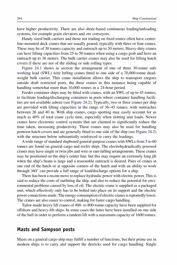
have higher productivity. There are also shore-based continuous loading/unloadingsystems, for example grain elevators and ore conveyors.
Handy sized bulk carriers and those not trading on fixed routes often have center-line-mounted deck cranes that are usually geared, typically with three or four cranes.These may be of 30 tonnes capacity and outreach up to 30 meters. Heavy-duty cranescan have lifting capacities from 25 to 50 tonnes when using a cargo grab and have anoutreach up to 36 meters. The bulk carrier cranes may also be used for lifting hatchcovers if these are not of the sliding or side rolling types.
Figure 24.1 shows in section the arrangement of one of three 30-tonne safeworking load (SWL) wire luffing cranes fitted to one side of a 70,000-tonne dead-weight bulk carrier. This crane installation allows the ship to transsport cargoesoutside draft restricted ports, the three cranes in this instance being capable ofhandling somewhat more than 10,000 tonnes in a 24-hour period.
Feeder container ships may be fitted with cranes, with an SWL of up to 45 tonnes,to facilitate loading/discharging containers in ports where container handling facili-ties are not available ashore (see Figure 24.2). Typically, two or three cranes per shipare provided with lifting capacities in the range of 36–45 tonnes, with outreachesbetween 26 and 40 m. With ship cranes, cargo spotting may easily account for asmuch as 40% of total crane cycle time, especially when slotting unit loads. Newercranes have electronic control systems that are claimed to significantly reduce thetime taken, increasing productivity. These cranes may also be used for handlingpontoon hatch covers and are generally fitted to one side of the ship (see Figure 24.2)with the structure below substantially reinforced to carry the loadings.
Awide range of standard shipboard general-purpose cranes with SWLs from 5 to 60tonnes are found on general cargo and reefer ships. The electrohydraulically poweredcranes may have single or twin jibs and wire or ram luffing arrangements. These cranesmay be positioned on the ship’s center line, but this may require an extremely long jibwhen the ship’s beam is large and a reasonable outreach is desired. Pairs of cranes atone end of the hatch or at opposite corners of the hatch and with an ability to workthrough 360� can provide a full range of load/discharge options for a ship.
There has been a recent move to replace hydraulic power with electric power. This issaid to reduce the costs of outfitting the ship, and also to reduce the potential for envi-ronmental problems caused by loss of oil. The electric crane is supplied as a packagedunit, which effectively only has to be bolted into place on its support and the electricpower connectionsmade. The energy consumption of electric cranes is reportedly lower.The cranes are also easier to control, making for faster cargo handling.
Tailor-made heavy lift cranes of 400- to 800-tonne capacity have been supplied foroffshore and heavy-lift ships. In some cases the latter have been installed on one sideof the hull in order to perform a tandem lift with a maximum capacity of 1600 tonnes.
Masts and Sampson posts
Masts on a general cargo ship may fulfill a number of functions, but their prime use inmodern ships is to carry and support the derricks used for cargo handling. Single
294 Ship Construction

masts are often fitted, but many ships now have various forms of bipod mast, whichare often more suitable for supporting derricks, although some types can restrict theview from the bridge. Sampson posts are often fitted at the ends of houses and mayalso be found at the other hatches.
The strength of masts and Sampson posts is indicated by the classification soci-eties. As a result of the span loads and derrick boom thrusts, a single mast or post maybe considered similar to a built-in cantilever with axial and bending loads. Sometorque may also be allowed for where the post has a cross-tree arrangement to an
Heavy derrick Mast
Derrick stool
Insert plate
Winch deck
Center-linebulkhead
Center-line girder
Transversebulkhead Upper deck
Insert plate
Stiffenercenter-lineplate web
Upper tween deck
Lower tween deck
Bracket
Watertight bulkhead
Heavy bulkheadstiffener oncenter line
Stiffener oncenter girder
Bracket
Tank top
Figure 24.1 Cross-section of bulk carrier with side mounted 30-tonne wire luffing cranes.
Cargo lifting arrangements 295

Topping block
Span
Span lead Cargo purchase
Slewing guyCargolead
SINGLESWINGINGDERRICK
(a)
Heel blockStanding guy
(b) UNION PURCHASE RIG
Outboardboom
Standingguy
Cargorunner
Boomplumbinghatch
Hatch
(d) YO-YO RIGS(c) BUTTERFLYRIG
Cargo runner
Standingguy
Hatch
Standingguy
Shackle
Figure 24.2 520 TEU container feeder ship fitted with two 40-tonne ram luffing cranes.
296
Ship
Constru
ction

adjacent post. Where shrouds and preventers are fitted these must be allowed for,which makes the calculations somewhat more difficult. In modern ships there isa tendency to simplify the rigging, which can restrict cargo handling. Shrouds areoften dispensed with and preventers may only be rigged when heavy derricks areused. Each mast or post has adequate scantlings so that they may remain unstayed.
Mast construction and stiffening
Tubular steel sections are commonly used in mast and post construction, the sectionsbeing rolled in short lengths and welded in the shipyard. The short lengths may betapered and are of different plate thicknesses to allow for the greater stresses expe-rienced at the base of the mast. Where connections are made for fittings such as thegooseneck and a masthead span swivel, doubling or welded reinforcing pads may beprovided. To obtain the necessary mast scantlings, excessive doubling or internalstiffeners are rarely found in modern practice, except where a heavier derrick than thatfor which the mast was originally designed is carried. Higher tensile steels are oftenused to advantage in mast construction, giving less weight high up in the ship anddispensing with the need for any form of support, without excessive scantlings.
Cross-trees, mast tables, etc. may be fabricated from welded steel plates andsections.
Derrick booms are as a rule welded lengths of seamless tubular steel. The middlelength may have a greater diameter to allow for the bending moment, to which theboom is subject in addition to the axial thrust.
At the base of the mast adequate rigidity must be provided, the amount of additionalstructural stiffening increasing with the size of derricks carried by the mast. Manycargo ships have mast houses into which the masts are built, the house being suitablystrengthened. These houses need not be designed to support the mast, the structurebeing of light scantlings and the support provided by stiffening in the tweens. Wherethe house is strengthened the masts or posts generally land on the upper deck, butwhere heavy derricks are installed the mast may then land on the upper tween deck.Since the derricks and mast are as a rule midway between holds they land over the holdtransverse bulkheads, which lend further support.
Heavy derrick masts will require extensive stiffening arrangements in the masthouse, and also in the tweens, with support for the transverse bulkhead so that theloads are transmitted through the structure to the ship’s bottom. Partial longitudinaland transverse bulkheads with deck girders may provide the mast house stiffening.Stiffened plate webs at the ship’s center line in the tweens and heavier stiffeners on thetransverse bulkhead in the hold then provide the additional strengthening below decks(see Figure 24.3). Heavy insert plates are fitted in way of the mast at the various decks.
Derrick rigs
Various forms of derrick rig may be used aboard the cargo ship, the commonest use ofthe single derrick being as a ‘single swinging derrick’ (see Figure 24.4a). Adjacent
Cargo lifting arrangements 297

(a) HALLEN SWINGINGDERRICK
Outrigger stays
Outrigger
Topping / slewingwinch
Derrick controljoy stick
Cargo hoist control
Cargo hoist winch
Topping/slewing winch
5 tonnederrick
Roller bearingheel fitting
Controlplatform
(b) 80 TONNESTULKENDERRICK
Cargo purchase lead
Slewing andtopping lead
Cargo purchase
Head swivels
Cargo and toppingwinches
Figure 24.3 Stiffening in way of mast and heavy derrick.
298
Ship
Constru
ction

derrick booms may be used in ‘union purchase’ (Figure 24.4b), the booms being fixedin the overboard and inboard positions. Cargo is lifted from the hatch and swungoutboard by the operator controlling the winches for the cargo runner. Variations onthis rig are often adopted, for example the ‘butterfly’ rig (Figure 24.4c), which is usedwhere cargo is discharged from a hold to both sides of the ship.
Swivel for derrick headspan block
Eye plate welded thro’derrick
Span load
Welded lugs forslewing guys
Spa
n pu
ll Resultant load on span blockMast
Shrunk and weldedtubular sections
Cargopurchase
Der
rick
boom
Boom
thru
st
Span load
S.W.L.
Pull
in le
ad
S.W
.L.+
Car
go p
urch
ase
+ H
alf b
oom
Saf
e w
orki
ng lo
ad
Res
ulta
nt o
n ca
rgo
head
blo
ck
Resultant load on
heel blockPull
in le
ad
Pull to winch
Gooseneck seatwelded thro’ mast
Figure 24.4 Derrick rigs.
Cargo lifting arrangements 299
Where a weight exceeding the safe working load of the derricks is to be lifted, the‘yo-yo’ rig is sometimes adopted (Figure 24.4d). The heads of the derricks arebrought together, and a traveling block may be arranged on the cargo runner or a wireconnecting the two cargo purchases as illustrated.
Both the ‘butterfly’ and ‘yo-yo’ rigs give a load pattern similar to the ‘unionpurchase’ and ‘single swinging derrick’ rigs for which calculations are made, but theguy loads with each can be particularly severe.
Patent derricks are generally of the single swinging type with some form ofpowered slewing. The Hallen swinging derrick is shown diagrammatically inFigure 24.5a. This type of derrick may be installed at the ship’s center line to reachoutboard on both sides of the ship and is controlled by a single operator in a mannernot unlike the operation of a mechanical crane. As a rule the safe working load of thistype of derrick is between 10 and 80 tonnes.
Of particular note in the very heavy lifting range is the patent Stulken derrick(Figure 24.5b) marketed by Blohm and Voss AG, which may have a safe working loadof between 80 and 300 tonnes. One advantage that this derrick has is its ability toserve two hatches, the boom swinging through an arc between the posts in the fore andaft directions.
Forces in derrick rigs
The geometry of the derrick rig will to a large extent influence the loads carried by therig components. Those dimensions that have the greatest influence are the length ofboom, the distance between the boom heel and the masthead span connection (heightof suspension), and the angle at which the boom is topped.
When the ratio between boom length and height of suspension is increased, theboom thrust will be higher; therefore, should a long boom be required the height ofsuspension must be adequate. It is not unusual, however, for shipowners to object tohaving posts at the bridge front and if the height of suspension is then restricted thereis some limitation on the boom length, which can make working cargo from thatposition difficult. The angle at which the derrick is topped has no effect on the axialthrust, but the lead from the cargo purchase often increases the thrust as it is ledparallel to the boom on all except heavy lift derricks.
Loads carried by the span are dependent on both the ratio of boom length to height ofsuspension and the angle atwhich thederrick is topped. The span load is greater at a lowerangle to the horizontal, and increases with longer booms for a given suspension height.
To determine these forces simple space and force diagrams may be drawn and theresultant forces determined to give the required wire sizes, block and connection safeworking loads, and the thrust experienced by the boom. The horizontal and verticalcomponents of the span load and boom thrust are also used to determine the mastscantlings. Force diagrams are shown for the rig components of the single swingingderrick illustrated in Figure 24.6.
For a safe working load of 15 tonnes or less the forces may be calculated with thederrick at angles of 30� and 70� to the horizontal unless the owner specifies that thederrick is to be used at a lower angle (not less than 15�). At safe working loads greater
300 Ship Construction

Limitingheight
Curve oflimiting heights(runners at 120° atany point of curve)
Loads vary in runnersat 120° included angleunless boom heads arelevel.
2 Tonnes
Outboard runner load
1.8 Tonnes
2.1 Tonnes
Inboard runner load
Inbo
ard
boom
Outboard boom
+
120°
120° 90°
30°
Note:
Figure 24.5 Patent derricks.
Carg
oliftin
garran
gem
ents
301

Figure 24.6 Forces in single swinging derrick rig.
302
Ship
Constru
ction

than 15 tonnes the forces may be calculated at an angle of 45� to the horizontal. Theloads on all the blocks except the lower block of a cargo purchase will be the resultantof the two forces to which the block is subjected. A single-sheave block has a safeworking load that is half the resultant, and multi-sheave blocks have a safe workingload that is the same as the resultant.
In determining the span loads and boom thrusts, not only is the derrick safeworking load considered to be supported by the span, but also the weight of the cargopurchase and half the boom weight. The other half of the boom weight is supported bythe gooseneck fitting.
Allowances must be made for the frictional resistance of the blocks when deter-mining the forces. This includes an allowance for the rope friction, i.e. the effortrequired to bend and unbend the rope around the pulley, as well as an allowance forjournal friction. Shipbuilders using British Standards adopt the following assumedcumulative friction values:
Small and medium sheaves 8% sheave with bushed plain bearings5% sheave with ball or roller bearings
Large diameter sheaves 6% sheave with bushed plain bearings4% sheave with ball or roller bearings
Derrick exceeding 80 tonnes SWL 5% sheave with bushed plain bearings3% sheave with ball or roller bearings
Force diagrams that are more involved than those for the single swinging derrick areprepared for the union purchase rig. These diagrams indicate the safe working load ofthe rig, the ‘limiting height’, the boom thrusts (which are greater with this rig), and theoptimum guy leads. The ‘limiting height’ is that height below which all positions ofthe lifted weight will result in an included angle between the outboard and inboardrunners of less than 120�. At 120�, if the boom heads are level the inboard andoutboard runners will experience a force equivalent to the cargo weight (seeFigure 24.7). Usually the runner size determines the safe working load in unionpurchase, but the thrust experienced by the derrick boom can determine this valuewhere only light derricks are fitted. The positioning of the guys may be important tothe loads experienced by the span and the guys themselves. If these are at too narrowan angle to the boom, excessive tension in the guys will result; a good lead is thereforeessential. Unfortunately, in practice the magnitude of the guy loads is not alwaysappreciated, but more attention has been paid to this problem of late and preventers arenow often set up to reduce the load in the guy. There is available a suitable preventerfor this purpose; the use of old runners etc. as preventers should not be tolerated.
In union purchase rigs it is possible to obtain a condition where the load comes offthe outboard span, and the boommay then close to the mast under load. This conditionis referred to as ‘jack-knifing’, and may be apparent from the force diagram preparedfor the rig, since the triangle of forces does not close. At the design stage the guypositions can be adjusted to avoid this happening. In practice this condition appears tooccur occasionally where derricks are used in union purchase at the bridge front. Herethe positioning of the guys is made difficult by the presence of the bridge structure, butthe correct placing of a suitable preventer should overcome this problem.
Cargo lifting arrangements 303

Initial tests and re-tests of derrick rigs
To comply with the national and class regulations, ships’ derricks designed to operateas single swinging derricks are initially tested with a proof load that exceeds thespecified safe working load of the derrick by the following amounts:
SWL less than 20 tonnes—25% in excess of SWLSWL 20–50 tonnes—5 tonnes in excess of SWLSWL over 50 tonnes—10% in excess of SWL.
Heavy-lift derricks are tested at an angle of not more than 45� to the horizontal andother derricks at an angle of not more than 30� to the horizontal. During the test theboom is swung as far as possible in both directions, and any derrick intended to beraised by power under load is raised to its maximum working angle at the outermostposition.
Before the test for a heavy derrick it is usual to ensure that the vessel has adequatetransverse stability. Before, during, and after all tests it is necessary to ensure thatnone of the components of the rig show signs of any failure, and it is good practice tohave a preventer rigged during the test as a precaution against any of the span gearcarrying away. On completion of the test the heel of the derrick boom is clearlymarked with:
1. Its safe working load in single purchase.2. Its safe working load in double purchase, if it is designed for that purpose.3. Its safe working load in union purchase, if it is designed for that purpose, the letter ‘U’
preceding the safe working load.
3–30 tonne S.W.L. wire luffing cranes mounted on 70,000 tonne deadweight bulk carrier
Figure 24.7 Forces in cargo runners of union purchase rig.
304 Ship Construction

For example,
SWL 3/5 tonnes SWL (U) 2 tonnes
and a certificate of test and examination is issued in an approved form.Re-tests are required if the rig is substantially modified or a major part is damaged
and repaired.The International Labour Organization (ILO) Convention, 152 adopted, 25 June
1979, requires thorough examination by a competent person once every 12 monthsand re-testing at least once every 5 years.
Further reading
British Standards Institution, BS MA 48:1976, Code of Practice for Design and Operation ofShips Derrick Rigs.
British Standards Institution, BS MA 47:1977, Code of Practice for Ships Cargo Blocks.British Standards Institution, BS MA 81:1980, Specification for Ships Derrick Fittings.Code for Lifting Appliances in a Marine Environment, Lloyd’s Register, 2003.House DJ: Cargo Work for Maritime Operations. Elsevier.ISO 8431:1988, Shipbuilding—Fixed jib cranes—Ship-mounted type for general cargo
handling, 2007.
Some useful websites
www.macgregor-group.com See ‘General cargo ships—Cranes’.
Cargo lifting arrangements 305

25 Cargo access, handling,and restraint
Chapter OutlineStern and bow doors 307Ramps 308Side doors and loaders 309Portable decks 311Scissors lift 312Cargo restraint 312Further reading 314Some useful websites 314
To speed cargo handling and storage in modern ships, apart from changes inship design (Chapter 3), the introduction of mechanically handled hatch covers(Chapter 19) and improved lifting devices (Chapter 24), various patented or speciallymanufactured items may be brought into the shipyard and fitted to the ship by theshipbuilder. Some notable items that fall into this category are described in thischapter. These primarily relate to cargo access handling and restraint in ro-ro ships,container ships, car carriers, and vessels in which palletized cargo is carried.
Stern and bow doors
Roll-on roll-off (ro-ro) vessels are used primarily on short sea crossings and aredesigned to carry road vehicles. They provide a link in a road journey, often overnight,and the speed of loading and unloading is often critical. The vehicles are driven onand off using large doors and a series of ramps to access different deck levels.
Ro-ro vessels may be fitted with stern doors of the hinge-down or hinge-up type,which if large are articulated. Bow doors are either of the visor type or of the side-hinged type (‘barn door’ type). These are situated above the freeboard deck and wherethe bow doors lead to a complete or long forward enclosed superstructure, Lloyd’srequire an inner door to be fitted that is part of the collision bulkhead. This would alsobe in keeping with the SOLAS requirements for passenger ships, where the collisionbulkhead is to be extended weathertight to the deck next above the bulkhead deck, butneed not be fitted directly above that bulkhead. A sloping weathertight vehicle rampmay be fitted in some ships to form the collision bulkhead above the freeboard deck
Ship Construction. DOI: 10.1016/B978-0-08-097239-8.00025-8
Copyright � 2012 Elsevier Ltd. All rights reserved.
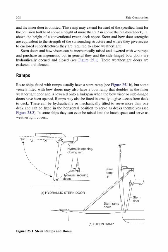
and the inner door is omitted. This ramp may extend forward of the specified limit forthe collision bulkhead above a height of more than 2.3 m above the bulkhead deck, i.e.above the height of a conventional tween deck space. Stern and bow door strengthsare equivalent to the strength of the surrounding structure and where they give accessto enclosed superstructures they are required to close weathertight.
Stern doors and bow visors can be mechanically raised and lowered with wire ropeand purchase arrangements, but in general they and the side-hinged bow doors arehydraulically opened and closed (see Figure 25.1). These weathertight doors arecasketed and cleated.
Ramps
Ro-ro ships fitted with ramps usually have a stern ramp (see Figure 25.1b), but somevessels fitted with bow doors may also have a bow ramp that doubles as the innerweathertight door and is lowered onto a linkspan when the bow visor or side-hingeddoors have been opened. Ramps may also be fitted internally to give access from deckto deck. These can be hydraulically or mechanically tilted to serve more than onedeck and can be fixed in the horizontal position to serve as decks themselves (seeFigure 25.2). In some ships they can even be raised into the hatch space and serve asweathertight covers.
Hydraulic opening/closing ram
Hydraulic securingcleats
(a) HYDRAULIC STERN DOOR
(b) STERN RAMP
Sterndoor
Sternrampup
Stern rampdown
Figure 25.1 Stern Ramps and Doors.
308 Ship Construction

Stern ramps can be fixed axial ramps, fixed quarter ramps, slewing ramps, or semi-slewing quarter ramps (see Figure 25.3). The axial stern ramp may also serve as thestern door and can be lowered or raised hydraulically or by wire rope arrangements.The quarter ramp was designed for ro-ro ships using ports that are not provided withright-angled quays or link span connections. The large articulated quarter ramp israised and lowered by wire rope purchase arrangements to hydraulic winches.Slewing ramps serve a similar purpose to the quarter ramp, but are more flexible. Theslewing ramp moves around the stern on a curved guide rail, the movement beingaffected by the lifting and lowering wire purchases, which are led to hydraulicwinches.
Side doors and loaders
Side door/ramps are available for ro-ro operations and are similar to stern door/rampinstallations. Most side door installations, however, are intended for quayside fork-liftoperations with palletized cargo being loaded onto a platform at the door by thequayside fork-lift and stowed in the ship by another fork-lift truck. Instead ofa loading platform on ships trading to ports with high tidal ranges a ramp onto whichthe quayside fork-lift truck drives may be fitted. Elevator platforms may be fittedimmediately inboard of the side door to service various tween decks and the hold.A particular type of elevator system is that developed for the transportation of paperproducts, especially newsprint. The quayside fork-lift places the newsprint rolls onthe height-adjustable loading platform, which together with the elevator platform isfitted with roller conveyors. Movement of the roller conveyors is automatic, the
Car deckStowed position
Loading position (to car deck)
Position at car deck level(cars would be on here)
PLAN VIEW OF RAMP
Vehicle ramp Down
Car deck
Figure 25.2 Internal Deck Access Ramps.
Cargo access, handling, and restraint 309

Quarter ramp
(a) LARGE STERN RAMP TYPES
Slewing ramp Semi-slewing ramp
Plan
Ramp stowed
Ramp down
(b) LARGE QUARTER RAMP
Elevation
Figure 25.3 Stern and Quarter Access Ramps.
310 Ship Construction
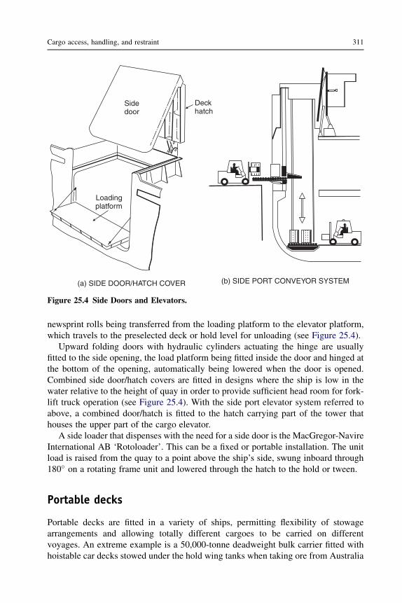
newsprint rolls being transferred from the loading platform to the elevator platform,which travels to the preselected deck or hold level for unloading (see Figure 25.4).
Upward folding doors with hydraulic cylinders actuating the hinge are usuallyfitted to the side opening, the load platform being fitted inside the door and hinged atthe bottom of the opening, automatically being lowered when the door is opened.Combined side door/hatch covers are fitted in designs where the ship is low in thewater relative to the height of quay in order to provide sufficient head room for fork-lift truck operation (see Figure 25.4). With the side port elevator system referred toabove, a combined door/hatch is fitted to the hatch carrying part of the tower thathouses the upper part of the cargo elevator.
A side loader that dispenses with the need for a side door is the MacGregor-NavireInternational AB ‘Rotoloader’. This can be a fixed or portable installation. The unitload is raised from the quay to a point above the ship’s side, swung inboard through180� on a rotating frame unit and lowered through the hatch to the hold or tween.
Portable decks
Portable decks are fitted in a variety of ships, permitting flexibility of stowagearrangements and allowing totally different cargoes to be carried on differentvoyages. An extreme example is a 50,000-tonne deadweight bulk carrier fitted withhoistable car decks stowed under the hold wing tanks when taking ore from Australia
(a) SIDE DOOR/HATCH COVER (b) SIDE PORT CONVEYOR SYSTEM
Loadingplatform
Sidedoor
Deckhatch
Figure 25.4 Side Doors and Elevators.
Cargo access, handling, and restraint 311
to Japan, and lowered for the return voyage when 3000 cars are carried. The car deckis the most common form of portable deck and common in ro-ro ferries. Eithercommercial vehicles can be loaded using the full height between decks or, with theportable deck in place, two levels of cars can be carried in the same space. Hoistabledecks are lowered from and stowed at the deckhead by hoist wires led througha hydraulic jigger winch. Folding decks stow at the sides and ends of ship spaces andare generally hydraulically lowered into the horizontal position. Lloyd’s Registerincludes requirements for movable decks in their rules and if the ship is fitted withportable decks complying with these rules at the owner’s or builder’s request the classnotation ‘movable decks’ may be assigned.
Scissors lift
Cargo can be lowered or raised between decks or to the hold by means of a scissorslift, which is sometimes fitted in ro-ro ships as an alternative to internal ramps, as ittakes up less room. However, the scissor lift is slower in operation than ramps. Thehydraulic cylinder-powered scissors lift is also often designed to transfer heavy unitloads.
Cargo restraint
In ro-ro and container ships the lashing of cargo is an important safety considerationand usually calls for fittings that will permit rapid and easy but effective securing ofthe cargo because of short ship turnaround times. The shipbuilder is responsible forthe deck and perhaps hatch fittings for the securing devices, and will look to the shipoperator for guidance on their type and positions. On the decks of ro-ro ships wherethe direction of lashing is unpredictable and vehicles must transverse the fitting,a cloverleaf deck socket in conjunction with an elephant’s foot type of end lashing ispopular (see Figure 25.5).
Containers have very little strength in any direction other thanvertically through thecorner posts, thus it is necessary to provide substantial support to the containers whenthey are on the ship. Stowage of containers is with their longer dimension fore and aftsince the ship motion transmitted to cargo is greater in rolling than pitching and it istherefore prudent to limit any possible cargo movement within the container to theshorter transverse dimension. Also, of course, when offloading the fore and aftcontainer is more easily received by road or rail transport. Below-decks containers arerestrained in vertical cell guides, which are typically 150 � 150 � 12 angles and theyare structurally supported so that any dynamic forces other than purely vertical aretransmitted asmuch as possible through the ship’s structure and not into the containers.The cell guides are not to form an integral part of the ship’s structure, they are to be sodesigned that they do not carry the main hull stresses.Where four container corners areadjacent the cell guides may be built into a composite pillar (see Figure 25.5). Theclearance between container and cell guide is critical. If it is too small the container will
312 Ship Construction

jam, if it is too large when one container lands on the one below the corner posts andcastings that accept a maximum eccentricity may not mate. Lloyd’s stipulatea maximum clearance of 25 mm in the transverse direction and 40 mm in the longi-tudinal direction. The tolerances are such that the cell guides have to be fitted to anaccuracy exceeding normal shipyard practice with the use of jigs to ensure thedimensions are maintained following welding. Lloyd’s require that the cell guide notdeviate from its intended line by more than 4 mm in the transverse direction and 5 mmin the longitudinal direction. Lead-in devices are fitted at the top of the guides.
Above-deck cell guides may also be provided, there being several patentedarrangements such as the MacGregor-Navire International AB ‘Stackcell’ system.
(a) CLOVERLEAF SOCKETAND ELEPHANT’S FOOTTIE-DOWNS
Container
Stacker
(c) DECK FITTING
Raised decksocket
Verticalgirder 150 × 150 × 12
20 mm
300 × 20
(b) CELL GUIDES
Figure 25.5 Container Guides and Lashing Points.
Cargo access, handling, and restraint 313

These are not widely used, however, and many ships carrying containers above deckrely on various deck and hatch sockets with locking and nonlocking stackers matingwith the standard container corners, plus lashings to secure the containers. Withlocking stackers fewer lashings are required, therefore the more expensive twistlock isoften favored. Deck sockets like the container corner fitting contain the standard ISOhole into which the stackers fit (see Figure 25.5).
Further reading
Anderson, Alexandersson, and Johansson, Cargo Securing and Cargo Shift on Passenger/Ro-Ro Vessels. RINA Conference on RO RO Safety, June 1996.
Code of Safe Practice for Cargo Stowage and Securing. IMO publication (IMO-292E), 2003edition, 2003.
House DJ: Cargo Work for Maritime Operations, ed 7. Elsevier, 2003.Knot JR: Lashing and Securing of Deck Cargoes, ed 3, London, 2002, The Nautical Institute.RINA Conference, Safety of Ro-Ro Passenger Vessels. Conference Proceedings – Royal
Institution of Naval Architects Publications, 1996.
Some useful websites
www.tts-se.com For details of ramps, doors, lifts, car decks, side loading systems, etc.
314 Ship Construction

26 Pumping and pipingarrangements
Chapter OutlineBilge and ballast pumping and piping 315
Bilge suctions 316Bilge pumps and pipe systems 316Scuppers 318
General service pipes and pumping 318Air and sounding pipes 319Sea inlets 319Cargo pumping and piping arrangements in tankers 320
Single product/crude oil carrier 320Multi-product tankers 321Cargo pumps 321Cargo tank ventilators 321Cargo tank protection 321Inert gas system 324Cargo tank purging and gas freeing 324Cargo tank washing 324
Further reading 325Some useful websites 325
In the construction of a merchant ship the shipbuilder is concerned with the instal-lation of the statutory bilge drainage, ballasting, general services, and where requiredthe liquid cargo loading and discharging, pumping and piping arrangements.Arrangements may also be fitted in tankers for tank washing and for introducing inertgas into the tanks.
Bilge and ballast pumping and piping
All cargo ships are provided with pumping and piping arrangements so that anywatertight compartment or watertight section of a compartment can be pumped outwhen the vessel has a list of up to 5� and is on an even keel. In the case of passengerships, each compartment or section of a compartment may be pumped out followinga casualty under all practical conditions whether the ship is listed or not.
Ship Construction. DOI: 10.1016/B978-0-08-097239-8.00026-X
Copyright � 2012 Elsevier Ltd. All rights reserved.

The arrangements in the machinery space are such that this space may be pumpedout through two suctions under the above conditions. One suction is from the mainbilge line and the other from an independent power-driven pump. An emergency bilgesuction is also provided in machinery spaces, and may be connected to the maincirculating water pump (for condenser) in steam ships, or the main cooling waterpump in motor ships.
Bilge suctions
As the vessel is to be pumped out when listed it is necessary to fit port and starboardsuctions in other than very narrow spaces. Generally, vessels are designed to havea moderate trim by the stern in service, and the suctions will therefore be placed in theafter part of the compartment. However, where a ship has a single hold that exceeds33.5m in length suctions are also arranged in the forwardhalf length of thehold.Onmanyvessels a sloping margin plate is fitted and a natural bilge is formed with the suctionsconveniently locatedwithin this recess. Adequate drainage to the bilge is providedwherea ceiling covers this space. If, however, the tank top extends to the ship sides, bilge wellshaving a capacity of at least 0.17m3may be arranged in thewings of the compartment. Ina passenger ship thesebilgewellsmust not extend towithin 460mmof the bottomshell soas to retain a reasonable margin of safety where the inner bottom height is effectivelyreduced. The shaft tunnel of the ship is drained bymeans of awell located at the after end,and the bilge suction is taken from the main bilge line (see Figure 26.1).
At the open ends of bilge suctions in holds and other compartments, outside themachinery space and shaft tunnel, a strum box is provided. The strum box isa perforated plate box welded to the mouth of the bilge line (Figure 26.1), whichprevents debris being taken up by the bilge pump suction. Perforations in the strumbox do not exceed 10 mm in diameter, and their total cross-sectional area is at leasttwice that required for the bore of the bilge pipe. Strums are arranged at a reasonableheight above the bottom of the bilge or drain well to allow a clear flow of water and topermit easy cleaning. In the machinery space and shaft tunnel the pipe from the bilgesis led to the mud box, which is accessible for regular cleaning. Each mud box containsa mesh to collect sludge and foreign objects entering the end of the pipe.
Bilge pumps and pipe systems
Cargo ships have at least two power-driven bilge pumping units in the machineryspace connected to the main bilge line, and passenger ships have at least three.
In passenger ships the power-driven bilge pumps are, where practicable, placed inseparate watertight compartments, so that all three are not easily flooded by the samedamage. Where the passenger ship has a length in excess of 91.5 m it is a requirementthat at least one of these pumps will always be serviceable in reasonable damagesituations. A submersible pump may be supplied with its source of power above thebulkhead deck. Alternatively, the pumps are so distributed throughout the length ofthe ship that it is inconceivable that one might not be able to work in the event ofreasonable damage.
316 Ship Construction

No. 5
Tunnelhold
Engineroom
No. 1hold
No. 2hold
No. 3hold
No. 4hold
BILGE STRUM
Bilge pipe Side ofsuper-structure
SCUPPER ABOVEFREEBOARD DECK
Welded pipescupper
Waterway
Direct suction
To fordholds
Bilge main
Valve chestDirectsuction
Mudbox
Emergency suction
Generalservicepump
Ballastpump
Bilgepump
To afthold
TunnelENGINEROOM
Figure 26.1 Bilge piping arrangement.
Pumpingandpipingarran
gem
ents
317

Suction connections are led to each hold or compartment from the main bilge line.Valves are introduced to prevent onewatertight compartment frombeing placed in directcommunication with another, and to prevent dry cargo spaces and machinery spacesbeing placed in direct communication with tanks or pumps having sea inlets. Thesescrew-down nonreturn valves are often provided in a bilge valve distribution chest, ormay befitted directly in the connections to the bilgemain. The bilge pipes that are used todrain cargo and machinery spaces are kept separate from the sea inlet pipes and ballastpipes, which are used for filling or emptying tanks where the water and oil are carried.Often a separate ‘dirty ballast’ system is arranged to overcome this problem.
If possible, the bilge pipes are kept out of the double-bottom tanks, and in way ofa deep tank are led through a pipe tunnel. If the peaks are used as tanks then a power pumpsuction is led to each peak. Only two pipes are permitted to pass through the collisionbulkhead below the bulkhead deck and a screw-down valve operated from above thebulkhead deck is provided for each pipe in a chest on the forward side of the bulkhead.Anindicator is provided to show at the valve operating position whether it is open or closed.
Bilge mains in passenger ships are kept within 20% of the ship’s beam of the sideshell, and any piping outside this region or in a duct keel is fitted with a nonreturnvalve. These requirements are intended to prevent any compartment from becomingflooded when the ship is grounded or otherwise damaged and a bilge pipe is severed.Many passenger ships are provided with divided deep tanks or side tanks that permitcross-flooding arrangements limiting the list after a casualty. This cross-flooding isgenerally controlled by valves operated from above the bulkhead deck, but self-actingarrangements can also be adopted.
Bilge and ballast piping may be of cast or wrought iron, steel, copper, or otherapproved materials. Lead or other heat-sensitive materials are not permitted. Thepiping is fitted in lengths that are adequately supported and have flanged connections,provision being made for expansion in each range of pipes.
Scuppers
Scuppers are fitted at the ship’s side to drain the decks. Figure 26.1 shows a scupper fittedabove the freeboard deck. Below the freeboard deck andwithin the intact superstructuresand houses on the freeboard deck fitted with weathertight doors, these scuppers may beled to the bilges. Alternatively, they may be led overboard provided that:
1. The freeboard is such that the deck edge is not immersed when the ship heels to 5�; and2. The scuppers are fitted with means of preventing water from passing inboard (usually
a screw-down nonreturn valve capable of being operated from above the freeboarddeck).
General service pipes and pumping
Pumps and substantial piping systems are provided in ships to supply the essentialservices of hot and cold fresh water for personal use, and salt water for sanitary andfirefighting purposes.
318 Ship Construction

Many large passenger ships are provided with a large low-pressure distilling plant forproducing freshwater during thevoyage, as the capacities requiredwouldotherwise needconsiderable tank space.This space isbetter utilized to carryoil fuel, improving the ship’srange. Independent tanks supplying the fresh water required for drinking and culinarypurposes, and fresh washing water etc., may be taken from the double-bottom tanks, thepumps for each supply also being independent. Hot fresh water is supplied initially fromthe cold fresh water system, through a nonreturn valve into a storage-type hot waterheater fitted with heater coils, and then the heated water is pumped to the outlet.
The sanitary system supplies sea water for flushing water closets etc., and may beprovided with a hydropneumatic pump in cargo vessels, but on larger passenger shipswhere the demand is heavier, a continuously operating power pump is required.
It is a statutory requirement that a fire main and deck wash system should besupplied. This has hose outlets on the various decks, and is supplied by power-drivenpumps in the machinery spaces. Provision may be made for washing down the anchorchain from a connection to the fire main.
Air and sounding pipes
Air pipes are provided for all tanks to prevent air being trapped under pressure in thetank when it is filled, or a vacuum being created when it is emptied. The air pipes maybe fitted at the opposite end of the tank to the filling pipe and/or at the highest point ofthe tank. Each air pipe from a double-bottom tank, deep tanks that extend to the ship’sside, or any tank that may be run up from the sea, is led up above the bulkhead deck.From oil fuel and cargo oil tanks, cofferdams, and all tanks that can be pumped up, theair pipes are led to an open deck, in a position where no danger will result fromleaking oil or vapors. The heights above decks and closing arrangements are coveredby the Load Line Conditions of Assignment (see Chapter 31).
Sounding pipes are provided to all tanks, and compartments not readily accessibleand are located so that soundings are taken in the vicinity of the suctions, i.e. at thelowest point of the tank. Each sounding pipe is made as straight as possible and is ledabove the bulkhead deck, except in some machinery spaces where this might not bepracticable. A minimum bore of 32 mm is in general required for sounding pipes, butwhere they pass through refrigeration spaces, to allow for icing, a minimum bore of65 mm is required where the temperature is at 0 �C or less. Underneath the soundingpipe a striking plate is provided where the sounding rod drops in the bilge well etc.Sometimes a slotted sounding pipe is fitted to indicate the depth of liquid present, andthe closed end must be substantial to allow for the sounding rod striking it regularly.Various patent tank sounding devices are available and can be fitted in lieu ofsounding pipes, as long as they satisfy the requirements of the classification society.
Sea inlets
Where the piping system requires water to be drawn from the sea, for example fire andwashdeck, ballast and machinery cooling systems, the inlet valve is fitted to
Pumping and piping arrangements 319

a substantial box within the line of the shell plate containing the sea inlet opening (seeFigure 26.2). This opening is to have rounded corners and be kept clear of the bilgestrake if possible. The sea inlet box should have the same thickness as the adjacentshell but is not to be less than 12.5 mm thick and need not exceed 25 mm. Sea inlets intanker pump rooms within 40% of the ship’s midship length are required to havecompensation, generally in the form of a heavier insert plate in the shell. A grill maybe fitted over the opening and a sacrificial anode will normally be fitted because thevalve metal and steelbox set up a galvanic cell (see Chapter 27).
Cargo pumping and piping arrangements in tankers
Cargo pumps are provided in tankers to load and discharge cargo, and also to ballastsome of the tanks, which becomes necessary when making voyages in the unloadedcondition. Many modern tankers have clean ballast capacity and these tanks areserved by a separate pumping system.
The particular cargo pumping system adopted depends very much on the range ofcargo carried. A fairly straightforward system is available for the larger bulk oil carrier,carrying a single product. Where smaller tankers carry a number of oil products at onetime, which must be kept separate, the pumping system is more complex.
Single product/crude oil carrier
Where a single oil product is carried, and where larger tankers are designed solely tocarry crude oil, a single pump room is fitted aft, adjacent to the machinery spaces. Thepiping system is of the ‘direct line’ type, three or four lines being provided, each with
Anode
Sea inlet box
Sea inlet gridspositioned so thatbars are in foreand aft direction
Closingvalve
Mudbox
Sluicevalve
Figure 26.2 Sea inlet.
320 Ship Construction

suctions from a group of tanks (see Figure 26.3). Each pump discharge is led up to thedeck mains, which run forward to the transverse loading and discharging connections.
A few large tankers have a discharge system that relies on hydraulically controlledsluice valves in the tank bulkheads. These permit a flow of the oil to a commonsuction in the after tank space. Many large tankers partially adopt this system, sluicevalves being provided in the longitudinal bulkheads, and the oil is allowed to find itsway from the wing tanks to the center tanks. Suctions from the main cargo lines arelocated in the center tanks. Such an arrangement is shown in Figure 26.3, which alsoindicates the separate stripping system, and clean ballast lines.
Multi-product tankers
Where a number of oil products are carried, the more complex pumping arrangementsrequire two and in some cases three pump rooms to be fitted. One may be fitted aftadjacent to the machinery space, a second amidships, and where a third pump room isprovided this is forward. On many older tankers the piping was often arranged on the‘ring main’ system to provide flexibility of pumping conditions (see Figure 26.4). Toobtain the optimum number of different pumping combinations in modern multi-product carriers the tanks may be fitted with individual suction lines.
Cargo pumps
Initially, on modern tankers the main cargo pumps were of the centrifugal type,either geared turbine or motor driven, and had a very high pumping capacity, thoseon the large tankers being capable of discharging say 3500 m3/hour. Because of theirhigh capacities the centrifugal cargo pumps are unsuitable for emptying tankscompletely, and for this purpose reciprocating stripping pumps with capacities of,say, 350 m3/hour are provided with a separate stripping line. More recent develop-ments have seen the use of individual hydraulically driven submerged cargo pumpsin the cargo tanks with a single discharge line and the conventional pump roomdispensed with. Also, cargo tanks are being fitted with submerged cargo pumpsdriven by explosion-proof electric motors. Tanker cargo discharge systems are nowoften fully computerized.
Cargo tank ventilators
The cargo tank ventilators are to be entirely separate from air pipes from othercompartments of the tanker and positioned so that flammable vapor emissions cannotbe admitted to other spaces or areas containing any source of ignition.
Cargo tank protection
Oil tankers of less than 20,000 tonnes deadweight are required to be fitted with a fixeddeck foam system capable of delivering foam to the entire cargo tanks deck area andinto any tank the deck of which has been ruptured.
Pumping and piping arrangements 321

Machinery 9 8 7 6 5 4 3 2 1
Pump room
CARGO PIPING ARRANGEMENT ON SMALLER TANKER
Waterballast
Waterballast
Waterballast
Waterballast
Waterballast
Water
ballast
Waterballast
Waterballast
Waterballast
Waterballast
Pump
room
Loadingline
Cofferdam
Ballast lineStripping lineCargo line
Bulkhead valve
12345678910
Figure 26.3 Diagrammatic representation of direct line cargo piping arrangement.
322
Ship
Constru
ction

12
3
9 8 7 6 5 4 3 2 1Machinery
Pumproom
CARGO PIPING WITH PARTIAL FULL FLOW IN LARGE CRUDE OIL TANKER
Pumproom
Waterballast
Waterballast
Fillinglines
Deeptank
2 1345
Stripping lineCargo line Ballast line
Bulkhead valves
Figure 26.4 Diagrammatic representation of ring main cargo piping arrangement.
Pumpingandpipingarran
gem
ents
323
Oil tankers of 20,000 tonnes deadweight or more should have a fixed deck foamsystem and a fixed inert gas system.
Inert gas system
The inert gas system is to be so designed and operated as to render and maintain theatmosphere of the cargo tanks nonflammable, other than when the tanks are gas free.Hydrocarbon gas normally encountered in oil tanks cannot burn in an atmospherecontaining less than 11% of oxygen by volume, thus if the oxygen content in a cargotank is kept below, say, 8% by volume fire or explosion in the vapor space should notoccur. Inert gas introduced into the tank will reduce the air (oxygen) content.
On an oil tanker, inert gas may be produced by one of two processes:
1. Ships with main or auxiliary boilers normally use the flue gas, which contains typically only2–4% by volume of oxygen. This is scrubbed with sea water to cool it and to remove sulfurdioxide and particulates, and it is then blown into the tanks through a fixed pipe distributionsystem.
2. On diesel-engined ships the engine exhaust gas will contain too high an oxygen level for useas an inert gas. An inert gas generating plant may then be used to produce gas by burningdiesel or light fuel oil. The gas is scrubbed and used in the same way as boiler flue gas.
Nonreturn barriers in the form of a deck water seal, and nonreturn valve are main-tained between the machinery space and deck distribution system to ensure nopetroleum gas or liquid petroleum passes back through the system to the machineryspace.
The double-hull and double-bottom spaces of tankers required to have an inert gassystem are to have connections for the supply of inert gas.
Cargo tank purging and gas freeing
When the tanker is fitted with an inert gas system, the discharged cargo tanks arepurged until the hydrocarbon vapors in the cargo tanks have been reduced to less than2% by volume. Gas freeing may then take place at the cargo tank deck level.
For tankers not provided with an inert gas system the flammable vapor is dis-charged initially through the tank venting outlets specified by MARPOL. When theflammable vapor concentration at the outlet has been reduced to 30% of the lowerflammable limit, gas freeing can be continued at cargo tank deck level.
A range of portable gas-freeing fans with associated equipment is readily avail-able, with typical air movement ranging from 8000 to 15,000 cubic meters per hour.
Cargo tank washing
After discharge of cargoes, oil tanker cargo tanks can be cleaned by either hot or coldwater, fresh or sea water, or by crude oil washing. Water cleaning machines can befixed in a tank or may be portable, the portable machine being connected by hose toa deck water main before being introduced through a tank-cleaning hatch into thetank. Crude oil carriers can have fixed washing equipment in the tanks connected to
324 Ship Construction

the cargo pumps via cross-connections at the ship’s manifold to the cleaning main andcan use crude oil instead of water as the washing medium. This is usually done whilethe tanker is discharging cargo and it enables redissolving of oil fractions adhering tothe tank surfaces to take place so that these residues can be discharged with the cargo.There may then be no need to water wash tanks for the removal of residues unlessclean water ballast is to be carried in the tank.
Further reading
Code for the Construction and Equipment of Ships Carrying Dangerous Chemicals in Bulk(BCH Code). IMO publication (IMO-772E).
International Code for the Construction and Equipment of Ships Carrying DangerousChemicals in Bulk (IBC Code). IMO publication (IMO-100E).
MARPOL 73/78 Consolidated Edition. See Annex 1, Chapter I, Regulation 18: Pumping,piping and discharge arrangements for oil tankers, IMO publication (IMO-1B 520E),2002
MARPOL 2005, Amendments 2005. IMO publication (IMO-1525E).SOLAS Consolidated Edition. See Chapter II-2, Part D: Fire safety measures for tankers, IMO
publication (IMO-1D 110E), 2004
Some useful websites
www.imo.org/about/conventions/listofconventions/pages/international-convention-for-the-prevention-of-pollution-from-ships-(marpol).aspx
www.victorpyrate.com See ‘Tank washing machines’ and ‘Gas freeing fans’.
Pumping and piping arrangements 325

27 Corrosion control and antifoulingsystems
Chapter OutlineNature and forms of corrosion 327
Atmospheric corrosion 328Corrosion due to immersion 328Electrochemical nature of corrosion 328Bimetallic (galvanic) corrosion 330Stress corrosion 331Corrosion/erosion 331Corrosion allowance 333
Corrosion control 333Cathodic protection 333
Sacrificial anode systems 333Impressed current systems 334
Protective coatings (paints) 334Corrosion protection by means of paints 337
Antifouling systems 337Impressed current antifouling systems 337Antifouling paints 338
Painting ships 339Surface preparation 339Temporary paint protection during building 341Paint systems on ships 341
Below the waterline 342Waterline or boot topping region 342Superstructures 342
Cargo and ballast tanks 342Further reading 343Some useful websites 343
Nature and forms of corrosion
There is a natural tendency for nearly all metals to react with their environment. Theresult of this reaction is the creation of a corrosion product that is generallya substance of very similar chemical composition to the original mineral from whichthe metal was produced.
Ship Construction. DOI: 10.1016/B978-0-08-097239-8.00027-1
Copyright � 2012 Elsevier Ltd. All rights reserved.

Atmospheric corrosion
Protection against atmospheric corrosion is important during the construction ofa ship, both on the building berth and in the shops. Serious rusting may occur wherethe relative humidity is above about 70%; the atmosphere in many shipyards isunfortunately sufficiently humid to permit atmospheric corrosion throughout most ofthe year. However, even in humid atmospheres the rate of rusting is determinedmainly by the pollution of the air through smoke and/or sea salts.
Corrosion due to immersion
When a ship is in service the bottom area is completely immersed and the waterline orboot topping region may be intermittently immersed in sea water. Under normaloperating conditions a great deal of care is required to prevent excessive corrosion ofthese portions of the hull. A steel hull in this environment can provide ideal conditionsfor the formation of electrochemical corrosion cells.
Electrochemical nature of corrosion
Any metal, in tending to revert to its original mineral state, releases energy. Atordinary temperatures in aqueous solutions the transformation of a metal atom intoa mineral molecule occurs by the metal passing into solution. During this process theatom loses one or more electrons and becomes an ion, i.e. an electrically chargedatom, with the production of an electric current (the released energy). This reactionmay only occur if an electron acceptor is present in the aqueous solution. Thus, anycorrosion reaction is always accompanied by a flow of electricity from one metallicarea to another through a solution in which the conduction of an electric currentoccurs by the passage of ions. Such a solution is referred to as an electrolyte solution,and because of its high salt content sea water is a good electrolyte solution.
A simple corrosion cell is formed by two different metals in an electrolyte solution(a galvanic cell), as illustrated in Figure 27.1. It is not essential to have two differentmetals, as we shall see later. As illustrated, a pure iron plate and a similar pure copperplate are immersed in a sodium chloride solution that is in contact with oxygen at thesurface. Without any connection the corrosion reaction on each plate would be small.Once the two plates are connected externally to form an electrical path, then thecorrosion rate of the iron will increase considerably and the corrosion on the copperwill cease. The iron electrode, by means of which the electrons leave the cell and byway of which the conventional current enters the cell, is the anode. This is theelectrode at which the oxidation or corrosion normally takes place. The copperelectrode, by means of which the electrons enter the cell and by way of which theconventional current leaves the cell, is the cathode, at which no corrosion occurs.A passage of current through the electrolyte solution is by means of a flow of negativeions to the anode and a flow of positive ions to the cathode.
Electrochemical corrosion in aqueous solutions will result from any anodic andcathodic areas coupled in the solution, whether they are metals of different potential
328 Ship Construction

Conventional currentOxygen
Anodeiron
Cathodecopper
Conventional current
+ve ions
–ve ions
Sodium chloride solution
GALVANIC CELL
–ve ions –ve ions
Oxygen
Sea water
CORROSION CELL SET UP BY BREAKS INMILLSCALE OR PAINT FILM ON PLATE SURFACE
Millscale or paint
Anode
CathodeCathode
Figure 27.1 Corrosion cell.
Corro
sioncontro
landantifo
uling
system
s329

in the environment or they possess different potentials as the result of physicaldifferences on the metal surface. The latter is typified by steel plate carrying brokenmillscale in sea water (Figure 27.1) or corrosion currents flowing between areas ofwell-painted plate and areas of defective paintwork.
In atmospheric corrosion and corrosion involving immersion, both oxygen and anelectrolyte play an important part. Plates freely exposed to the atmosphere willreceive plenty of oxygen but little moisture, and the moisture present thereforebecomes the controlling factor. Under conditions of total immersion it is the presenceof oxygen that becomes the controlling factor.
Bimetallic (galvanic) corrosion
Although it is true to say that all corrosion is basically galvanic, the term ‘galvaniccorrosion’ is usually applied when two different metals form a corrosion cell.
Many ship corrosion problems are associated with the coupling of metallic parts ofdifferent potential, which consequently form corrosion cells under service conditions.The corrosion rates of metals and alloys in sea water have been extensively investi-gated and as a result galvanic series of metals and alloys in sea water have beenobtained. A typical galvanic series in sea water is shown in Table 27.1.
The positions of the metals in the table apply only in a sea water environment, andwhere metals are grouped together they have no strong tendency to form couples witheach other. Some metals appear twice because they are capable of having botha passive and an active state. A metal is said to be passive when the surface is exposedto an electrolyte solution and a reaction is expected but the metal shows no sign of
Table 27.1 Galvanic series of metals and alloys in sea water
Noble (cathodic or protected) endPlatinum, goldSilverTitaniumStainless steels, passiveNickel, passiveHigh-duty bronzesCopperNickel, activeMillscaleNaval brassLead, tinStainless steels, activeIron, steel, cast ironAluminum alloysAluminumZincMagnesiumIgnoble (anodic or corroding) end
330 Ship Construction
corrosion. It is generally agreed that passivation results from the formation ofa current barrier on the metal surface, usually in the form of an oxide film. This thinprotective film forms, and a change in the overall potential of the metal occurs whena critical current density is exceeded at the anodes of the local corrosion cells on themetal surface.
Among the more common bimetallic corrosion cell problems in ship hulls arethose formed by the mild steel hull with the bronze or nickel alloy propeller. Also,above-the-waterline problems exist with the attachment of bronze and aluminumalloy fittings. Where aluminum superstructures are introduced, the attachment to thesteel hull and the fitting of steel equipment to the superstructure require specialattention. This latter problem is overcome by insulating the two metals and preventingthe ingress of water, as illustrated in Figure 27.2. A further development is the use ofexplosion-bonded aluminum/steel transition joints, also illustrated. These joints arefree of any crevices, the exposed aluminum-to-steel interface being readily protectedby paint.
Stress corrosion
Corrosion and subsequent failure associated with varying forms of applied stress isnot uncommon in marine structures.
Internal stresses produced by non-uniform cold working are often more dangerousthan applied stresses. For example, localized corrosion is often evident at cold flangedbrackets.
Corrosion/erosion
Erosion is essentially a mechanical action but it is associated with electrochemicalcorrosion in producing two forms of metal deterioration. Firstly, in what is known as‘impingement attack’, the action is mainly electrochemical but it is initiated byerosion. Air bubbles entrained in the flow of water and striking a metal surface mayerode away any protective film that may be present locally. The eroded surfacebecomes anodic to the surrounding surface and corrosion occurs. This type of attackcan occur in most places where there is water flow, but particularly where featuresgive rise to turbulent flow. Sea water discharges from the hull are a particular case, theeffects being worse if warm water is discharged.
Cavitation damage is also associated with a rapidly flowing liquid environment.At certain regions in the flow (often associated with a velocity increase resulting froma contraction of the flow stream) the local pressures drop below that of the absolutevapor pressure. Vapor cavities, i.e. areas of partial vacuum, are formed locally, butwhen the pressure increases clear of this region the vapor cavities collapse or‘implode’. This collapse occurs with the release of considerable energy, and if itoccurs adjacent to a metal surface damage results. The damage shows itself as pitting,which is thought to be predominantly due to the effects of the mechanical damage.However, it is also considered that electrochemical action may play some part in thedamage after the initial erosion.
Corrosion control and antifouling systems 331
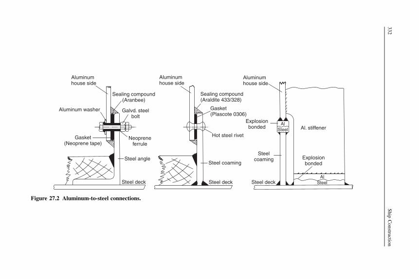
Aluminumhouse side
Aluminum washer
Sealing compound(Aranbee)
Galvd. steelbolt
Gasket(Neoprene tape)
Neopreneferrule
Steel angle
Steel deck
Gasket(Plascote 0306)
Aluminumhouse side
Sealing compound(Araldite 433/328)
Hot steel rivet
Steel coaming
Steel deck
Aluminumhouse side
Explosionbonded
AlSteel
AlSteel
Al. stiffener
Explosionbonded
Steelcoaming
Steel deck
Figure 27.2 Aluminum-to-steel connections.
332
Ship
Constru
ction

Corrosion allowance
Plate and section scantlings specified for ships in the rules of classification societiesinclude corrosion additions to the thickness, generally based on a 25-year service life.The corrosion allowance is based on the concept that corrosion occurs on the exposedsurface of the material at a constant rate, no matter how much material lies behind it.That is, if a plate is 8 or 80 mm thick, corrosion will take place at the same rate, not ata faster rate in the thicker plate. Some shipowners may specify thicker material than isrequired by the classification society, where there are plans for long-term ownership.
Corrosion control
The control of corrosion may be broadly considered in two forms, cathodic protectionand the application of protective coatings, i.e. paints.
Cathodic protection
Only where metals are immersed in an electrolyte can the possible onset of corrosionbe prevented by cathodic protection. The fundamental principle of cathodic protec-tion is that the anodic corrosion reactions are suppressed by the application of anopposing current. This superimposed direct electric current enters the metal at everypoint, lowering the potential of the anode metal of the local corrosion cells so thatthey become cathodes.
There are two main types of cathodic protection installation, sacrificial anodesystems and impressed current systems.
Sacrificial anode systems
Sacrificial anodes are metals or alloys attached to the hull that have a more anodic,i.e. less noble, potential than steel when immersed in sea water. These anodes supplythe cathodic protection current, but will be consumed in doing so and thereforerequire replacement for the protection to be maintained.
This system has been used for many years, the fitting of zinc plates in way ofbronze propellers and other immersed fittings being common practice. Initially,results with zinc anodes were not always very effective owing to the use of unsuitablezinc alloys. Modern anodes are based on alloys of zinc, aluminum, or magnesium,which have undergone many tests to examine their suitability; high-purity zinc anodesare also used. The cost, with various other practical considerations, may decide whichtype is to be fitted.
Sacrificial anodes may be fitted within the hull, and are often fitted in ballast tanks.However, magnesium anodes are not used in the cargo-ballast tanks of oil carriersowing to the ‘spark hazard’. Should any part of the anode fall and strike the tankstructure when gaseous conditions exist, an explosion could result. Aluminum anodesystems may be employed in tankers provided they are only fitted in locations wherethe potential energy is less than 28 kgm.
Corrosion control and antifouling systems 333

Impressed current systems
These systems are applicable to the protection of the immersed external hull only. Theprinciple of the systems is that a voltage difference is maintained between the hull andfitted anodes, which will protect the hull against corrosion, but not overprotect it, thuswasting current. For normal operating conditions the potential difference is maintainedby means of an externally mounted silver/silver chloride reference cell detecting thevoltage difference between itself and the hull. An amplifier controller is used toamplify the micro-range reference cell current, and it compares this with the presetprotective potential value that is to be maintained. Using the amplified DC signal fromthe controller, a saturable reactor controls a larger current from the ship’s electricalsystem that is supplied to the hull anodes. An AC current from the electrical systemwould be rectified before distribution to the anodes. Figure 27.3 shows such a system.
Originally consumable anodeswere employed, but in recent systems nonconsumablerelatively noblemetals are used; these include lead/silver and platinum/palladiumalloys,and platinized titanium anodes are also used.
A similar impressed current system employs a consumable anode in the form of analuminum wire up to 45 meters long that is trailed behind the ship whilst at sea. Noprotection is provided in port.
Although the initial cost is high, these systems are claimed to be more flexible, tohave a longer life, to reduce significantly hull maintenance, and to weigh less than thesacrificial anode systems.
Care is required in their use in port alongside ships or other unprotected steelstructures.
Protective coatings (paints)
Paints intended to protect against corrosion consist of pigment dispersed in a liquidreferred to as the ‘vehicle’. When spread out thinly the vehicle changes in time to anadherent dry film. The drying may take place through one of the following processes:
1. When the vehicle consists of solid resinous material dissolved in a volatile solvent, the latterevaporates after application of the paint, leaving a dry film.
2. A liquid like linseed oil as a constituent of the vehicle may produce a dry paint film byreacting chemically with the surrounding air.
3. A chemical reaction may occur between the constituents of the vehicle after application, toproduce a dry paint film. The reactive ingredients may be separated in two containers(‘two-pack paints’) and mixed before application. Alternatively, ingredients that only reactat higher temperatures may be selected, or the reactants may be diluted with a solvent so thatthe reaction occurs only slowly in the can.
Corrosion-inhibiting paints for application to steel have the following vehicle types:
1. Bitumen or pitch. Simple solutions of bitumen or pitch are available in solvent naphtha orwhite spirit. The bitumen or pitch may also be blended by heat with other materials to forma vehicle.
2. Oil based. These consist mainly of vegetable drying oils, such as linseed oil and tung oil.To accelerate the drying by the natural reaction with oxygen, driers are added.
334 Ship Construction

Anodes Anodes
From ship’s power
Reactorrectifier WaterlineController
Referencecell
Figure 27.3 Impressed current cathode protection system.
Corro
sioncontro
landantifo
uling
system
s335

3. Oleo-resinous. The vehicle incorporates natural or artificial resins into drying oils. Some ofthese resins may react with the oil to give a faster-drying vehicle. Other resins do not reactwith the oil but heat is applied to dissolve the resin and cause the oil to body.
4. Alkyd resin. These vehicles provide a further improvement in the drying time and film-forming properties of drying oils. The name alkyd arises from the ingredients, alcohols andacids. Alkyds need not be made from oil, as an oil-fatty acid or an oil-free acid may be used.(Note: Vehicle types 2 and 4 are not suitable for underwater service, and only certain
kinds of type 3 are suitable for such service.)5. Chemical resistant. Vehicles of this type show extremely good resistance to severe condi-
tions of exposure. As any number of important vehicle types come under this generalheading, these are dealt with individually.a. Epoxy resins. Chemicals that may be produced from petroleum and natural gas are
the source of epoxy resins. These paints have very good adhesion, apart from theirexcellent chemical resistance. They may also have good flexibility and toughness whereco-reacting resins are introduced. Epoxy resins are expensive owing to the removal ofunwanted side products during their manufacture, and the gloss finish may tend to‘chalk’, making it unsuitable for many external decorative finishes. These paints oftenconsist of a ‘two-pack’ formulation, a solution of epoxy resin together with a solution ofcold curing agent, such as an amine or a polyamide resin, being mixed prior to appli-cation. The mixed paint has a relatively slow curing rate at temperatures below 10 �C.Epoxy resin paints should not be confused with epoxy-ester paints, which are unsuitablefor underwater use. Epoxy-ester paints can be considered as alkyd equivalents, as theyare usually made with epoxy resins and oil-fatty acids.
b. Coal tar/epoxy resin. This vehicle type is similar to the epoxy resin vehicle except that,as a two-pack product, a grade of coal tar pitch is blended with the resin. A formulationof this type combines to some extent the chemical resistance of the epoxy resin with theimpermeability of coal tar.
c. Chlorinated rubber and isomerized rubber. The vehicle in this case consists of a solutionof plasticized chlorinated rubber, or isomerized rubber. Isomerized rubber is producedchemically from natural rubber, and it has the same chemical composition but a differentmolecular structure. Both these derivatives of natural rubber have a wide range ofsolubility in organic solvents, and so allow a vehicle of higher solid content. On drying,the film thickness is greater than would be obtained if natural rubber were used. Highbuild coatings of this type are available, thickening or thixotropic agents being added toproduce a paint that can be applied in much thicker coats. Coats of this type areparticularly resistant to attack from acids and alkalis.
d. Polyurethane resins. A reaction between isocyanates and hydroxyl-containing com-pounds produces ‘urethane’ and this reaction has been adapted to produce polymericcompounds from which paint film, fibers, and adhesives may be obtained. Paint films soproduced have received considerable attention in recent years, and since there isa variety of isocyanate reactions, both one- and two-pack polyurethane paints areavailable. These paints have many good properties: toughness, hardness, gloss, abrasionresistance, as well as chemical and weather resistance. Polyurethanes are not usedunderwater on steel ships, only on superstructures etc., but they are very popular onyachts, where their good gloss is appreciated.
e. Vinyl resins. Vinyl resins are obtained by the polymerization of organic compoundscontaining the vinyl group. The solids content of these paints is low; therefore, the dryfilm is thin and more coats are required than for most paints. As vinyl resin paints havepoor adhesion to bare steel surfaces they are generally applied over a pretreatment
336 Ship Construction

primer. Vinyl paint systems are among the most effective for the underwater protectionof steel.
6. Zinc-rich paints. Paints containing metallic zinc as a pigment in sufficient quantity to ensureelectrical conductivity through the dry paint film to the steel are capable of protecting thesteel cathodically. The pigment content of the dry paint film should be greater than 90%, thevehicle being an epoxy resin, chlorinated rubber, or similar medium.
Corrosion protection by means of paints
It is often assumed that all paint coatings prevent attack on the metal covered simplyby excluding the corrosive agency, whether air or water. This is often the main andsometimes only form of protection; however, there are many paints that affordprotection even though they present a porous surface or contain various discontinuities.
For example, certain pigments in paints confer protection on steel even where it isexposed at a discontinuity. If the reactions at the anode and cathode of the corrosioncell that form positive and negative ions respectively are inhibited, protection isafforded. Good examples of pigments of this type are red lead and zinc chromate, redlead being an anodic inhibitor and zinc chromate a cathodic inhibitor. A second modeof protection occurs at gaps where the paint is richly pigmented with a metal anodic tothe basis metal. Zinc dust is a commercially available pigment that fulfills thisrequirement for coating steel in a salt water environment. The zinc dust is thesacrificial anode with respect to the steel.
Antifouling systems
The immersed hull and fittings of a ship at sea, particularly in coastal waters, aresubject to algae, barnacle, mussel, and other shellfish growth that can impair itshydrodynamic performance and adversely affect the service of the immersed fittings.
Fittings such as cooling water intake systems are often protected by impressedcurrent antifouling systems, and immersed hulls today are finished with very effectiveself-polishing antifouling paints.
Impressed current antifouling systems
The functional principle of these systems is the establishment of an artificially trig-gered voltage difference between copper anodes and the integrated steel plate cath-odes. This causes a minor electrical current to flow from the copper anodes, so thatthey are dissolved to a certain degree. A control unit makes sure that the anodes addthe required minimum amount of copper particles to the sea water, thus ensuring theformation of copper oxide that creates ambient conditions precluding local fouling. Acontrol unit can be connected to the management system of the vessel. Using infor-mation from the management system, the impressed current antifouling system candetermine the amount of copper that needs to be dissolved to give optimum perfor-mance with minimum wastage of the anodes.
Corrosion control and antifouling systems 337

Antifouling paints
Antifouling paints consist of a vehicle with pigments that give body and colortogether with materials toxic to marine vegetable and animal growth. Copper is thebest known toxin used in traditional antifouling paints.
To prolong the useful life of the paint the toxic compounds must dissolve slowly insea water. Once the release rate falls below a level necessary to prevent settlement ofmarine organisms, the antifouling composition is no longer effective. On merchantships the effective period for traditional compositions was about 12 months. Demandsin particular from large tanker owners wishing to reduce very high docking costs ledto specially developed antifouling compositions with an effective life up to 24 monthsin the early 1970s. Subsequent developments of constant emission organic toxinantifoulings having a leaching rate independent of exposure time saw the painttechnologists by chance discover coatings that also tended to become smoother inservice. These so-called self-polishing antifoulings, with a lifetime that is propor-tional to applied thickness and therefore theoretically unlimited, smooth rather thanroughen with time and result in reduced friction drag. Though more expensive thantheir traditional counterparts, given the claim that each 10-micron (10�3 mm)increase in hull roughness can result in a 1% increase in fuel consumption, their self-polishing characteristic as well as their longer effective life, up to 5 years’ protectionbetween dry dockings, made them attractive to the shipowner.
The benefits of the first widely used self-polishing copolymer (SPC) antifoulingpaints could be traced to the properties of their prime ingredients, the tributyltincompounds or TBTs. TBTs were extremely active against a wide range of foulingorganisms and they were able to be chemically bonded to the acrylic backbone ofthe paint system. When immersed in sea water a specific chemical reaction tookplace that cleaved the TBT from the paint backbone, resulting in both controlledrelease of the TBT and controlled disappearance or polishing of the paint film.Unfortunately, it was found that the small concentrations of TBTs released,particularly in enclosed coastal waters, had a harmful effect on certain marineorganisms. This led to the banning of TBT antifouling paints for pleasure boats andsmaller commercial ships in many developed countries and the introduction ofregulations limiting the release rate of TBT for antifouling paints on larger ships.The International Convention on the Control of Harmful Antifouling on Ships, 2001subsequently required that:
1. Ships shall not apply or reapply organotin compounds that act as biocides in antifoulingsystems on or after 1 January 2003; and
2. No ship shall have organotin compounds that act as biocides in antifouling systems (exceptfloating platforms, FSUs, and FPSOs built before 2003 and not docked since before 2003).
The final phase-out of TBT paints was in 2008. In theory, ships could retain the paintif it was sealed under another coating but in practice TBTs are no longer at sea.
(Note: Organotin means an organic compound with one or more tin atoms inits molecules used as a pesticide, hitherto considered to decompose safely, nowfound to be toxic in the food chain. A biocide is a chemical capable of killing livingorganisms.)
338 Ship Construction

Antifouling paints subsequently applied have generally focused on either the useof copper-based self-polishing antifouling products, which operate in a similarmanner to the banned TBT products, or the use of the so-called low-surface-energycoatings. The latter coatings do not polish or contain booster biocides, instead theyoffer a very smooth, low-surface-energy surface to which it is difficult for fouling toadhere. When the vessel is at rest some fouling may occur but once it is underway andreaches a critical speed the fouling is released.
Painting ships
To obtain the optimum performance from paints it is important that the metal surfacesare properly prepared before application of paints and subsequently maintained assuch throughout the fabrication and erection process. Paints tailored for the serviceconditions of the structure to which they apply, and recommended as such by themanufacturer, only should be applied. It is common, especially for ships undergoinga regular dry-docking, for the coating process to be specified and managed by thecoating supplier.
Surface preparation
Good surface preparation is essential to successful painting, the primary cause ofmany paint failures being the inadequacy of the initial material preparation.
It is particularly important before painting new steel that any millscale should beremoved. Millscale is a thin layer of iron oxides that forms on the steel surface duringhot rolling of the plates and sections. Not only does the non-uniform millscale set upcorrosion cells, as illustrated previously, but it may also come away from the surfaceremoving any paint film applied over it. Any corrosion from storage of the steeloutdoors in a stockyard must also be removed.
It is also important to create a good surface for coating. Swedish standards areoften quoted, SA 3 being white metal and SA 2.5 being near white metal. SA 2.5 iscommon as a reasonably achieveable standard for shipyards. The surface is clean andthe blasting process also provides a ‘key’ with very small indentations to which thecoating adheres well.
The most common methods employed to prepare steel surfaces for painting are:
l Blast cleaningl Picklingl Flame cleaningl Preparation by handl High-pressure water blasting.
Blast cleaning is the most efficient method for preparing the surface and is in commonuse in all large shipyards. The shipyard preparation process has been outlined inChapter 13. Smaller shipyards, where the quantity of steel processed does not justifythe capital investment in the preparation equipment, usually buy steel alreadyprepared from a steel mill or stockist.
Corrosion control and antifouling systems 339

Following the blast cleaning it is desirable to brush the surface and apply a coat ofpriming paint as soon as possible, since the metal is liable to rust rapidly.
There are two main types of blasting equipment available, an impeller wheelplant where the abrasive is thrown at high velocity against the metal surface, anda nozzle type where a jet of abrasive impinges on the metal surface. The lattertype should preferably be fitted with vacuum recovery equipment, rather thanallow the spent abrasive and dust to be discharged to atmosphere, as is often thecase in ship repair work. Impeller wheel plants that are self-contained and collectthe dust and recirculate the clean abrasive are generally fitted within the ship-building shops.
Steel shot is the preferred blast medium for preparation of steel plates and profilesfor new construction. As the process proceeds the shot is recovered and reused. Theshot breaks down during the blasting and a mix of new and broken shot provides goodsurface preparation. Dust and other debris is filtered out of the recovery system fordisposal.
Cast iron and steel grit may be used for the abrasive, also copper slag, butnonmetallic abrasives are also available. Grit has been used in ship repair but isbecoming much less popular because of environmental issues associated withdisposal of the waste material. The use of sand is prohibited in most countries becausethe fine dust produced may cause silicosis.
Pickling involves the immersion of the metal in an acid solution, usually hydro-chloric or sulfuric acid, in order to remove the millscale and rust from the surface.After immersion in these acids the metal will require a thorough hot water rinse. It ispreferable that the treatment is followed by application of a priming coat. Pickling isno longer found in most of the ship construction industry.
Using an oxyacetylene flame the millscale and rust may be removed from a steelsurface. The process does not entirely remove the millscale and rust, but it can bequite useful for cleaning plates under inclement weather conditions, the flame dryingout the plate. Flame, or another heating process, is used as part of an automatedpreparation line in a shipyard, to preheat the steel, which assists the cleaning anddrying of the primer paint coating.
Hand cleaning by various forms of wire brush is often not very satisfactory, andwould only be used where the millscale has been loosened by weathering, i.e.exposure to atmosphere over a long period. For ships in service hand cleaning may beused for very small corroded areas.
High-pressure water blasting is superseding grit blasting for ship repair. It iscapable of restoring a steel surface to SA 2.5, provided any corrosion has not beenallowed to develop. Disposal of the waste material, in this case mainly water, is a mainreason for the adoption of water blasting.
Blast cleaning using shot or grit is preferred for best results and economy inshipbuilding, it is essential prior to application of high-performance paint systemsused today. Pickling, which also gives good results, can be expensive and lessapplicable to production schemes; flame cleaning is much less effective; and handcleaning gives the worst results. Water blasting is mainly a ship repair process.
340 Ship Construction

Temporary paint protection during building
After the steel is blast cleaned it may be several months before it is built into the shipand finally painted. It is desirable to protect the material against rusting in thisperiod as the final paint will offer the best protection when applied over perfectlyclean steel.
The formulation of a prefabrication primer for immediate application after blastingmust meet a number of requirements. It should dry rapidly to permit handling of theplates within a few minutes and working the plates within a day or so. It should benontoxic, and it should not produce harmful porosity in welds nor give off obnoxiousfumes during welding or cutting. For some high-speed welding processes it isnecessary to remove the primer in way of the welds to avoid porosity. After cuttingand welding, areas of damaged primer are usually strip coated by hand to cover theaffected steel and retain the primer protection against corrosion.
The primer must also be compatible with any subsequent paint finishes to beapplied. Satisfactory formulations are available, for example a primer consisting ofzinc dust in an epoxy resin.
Some shipyards where work is entirely undercover and where the steel is usedquickly may dispense with primer.
Given the sophistication and cost of modern, long-life coatings, their application iscritical to performance. It is common for shipyards to take complete units and blocks,once all the hot work is completed, for final coating in a controlled environment.So-called ‘paint cells’ are temperature- and humidity-controlled buildings. The unitsare driven into the cells using self-elevating transporters. The units are then blasted, ifno primer has been used or the primer is degraded and unsuitable for overcoating.Once cleaned the coatings can be applied in near ideal conditions. Hull and internalcoatings are applied.
Where the units are to be joined in the building dock, unpainted areas are left.These are completed after the hull welding, using localized protection from unsuit-able weather conditions.
Paint systems on ships
The paint system applied to any part of a ship will be dictated by the environment towhich that part of the structure is exposed. Traditionally, the painting of the externalship structure was divided into three regions:
1. Below the waterline, where the plates are continually immersed in sea water.2. The waterline or boot topping region, where immersion is intermittent and a lot of abrasion
occurs.3. The topsides and superstructure exposed to an atmosphere laden with salt spray, and subject
to damage through cargo handling.
However, now that tougher paints are used for the ship’s bottom the distinctionbetween regions need not be so well defined, one scheme covering the bottom andwaterline regions.
Corrosion control and antifouling systems 341
Internally, by far the greatest problem is the provision of coatings for various liquidcargo and salt water ballast tanks.
Below the waterline
The ship’s bottom has priming coats of corrosion-inhibiting paint applied that arefollowed by an antifouling paint. Paints used for steels immersed in sea water arerequired to resist alkaline conditions. The reason for this is that an iron alloyimmersed in a sodium chloride solution having the necessary supply of dissolvedoxygen gives rise to corrosion cells with caustic soda produced at the cathodes.Further, the paint should have a good electrical resistance so that the flow of corrosioncurrents between the steel and sea water is limited. These requirements make thestandard nonmarine structural steel primer red lead in linseed oil unsuitable for shipuse below the waterline. Suitable corrosion-inhibiting paints for ships’ bottoms arepitch or bitumen types, chlorinated rubber, coal tar/epoxy resin, or vinyl resin paints.The antifouling paints may be applied after the corrosion-inhibiting coatings andshould not come into direct contact with the steel hull, since the toxic compoundspresent may cause corrosion.
Waterline or boot topping region
Generally, modern practice requires a complete paint system for the hull above thewaterline. This may be based on vinyl and alkyd resins or on polyurethane resinpaints.
Superstructures
Red lead- or zinc chromate-based primers are commonly used. White finishing paintsare then used extensively for superstructures. These are usually oleo-resinous or alkydpaints that may be based on ‘nonyellowing’ oils, linseed oil-based paints that yellowon exposure being avoided on modern ships.
Where aluminum alloy superstructures are fitted, under no circumstance shouldlead-based paints be applied; zinc chromate paints are generally supplied for appli-cation to aluminum.
Cargo and ballast tanks
Severe corrosion may occur in a ship’s cargo tanks as the combined result of carryingliquid cargoes and sea water ballast, with warm or cold sea water cleaning betweenvoyages. This is particularly true of oil tankers. Tankers carrying ‘white oil’ cargoessuffer more general corrosion than those carrying crude oils, which deposit a film onthe tank surface, providing some protection against corrosion. The latter type may,however, experience severe local pitting corrosion due to the non-uniformity of thedeposited film, and subsequent corrosion of any bare plate when sea water ballast iscarried. Epoxy resin paints are used extensively within these tanks, and vinyl resinsand zinc-rich coatings may also be used.
342 Ship Construction

Further reading
Antifouling Systems 2005 Antifouling Systems—International Convention on the Controlof Harmful Antifouling Systems on Ships. IMO publication, 2005 edition.
Paint terminology explained, The Naval Architect, June 2003.Paints and coatings technology, The Naval Architect, June 2005.
Some useful websites
www.imo.org See under ‘Marine environment—Antifouling systems’.www.jotun.com See under ‘Technical papers—Marine coatings’ and ‘Products—Cathodic
protection’.www.hempel.com See under ‘Fouling control’, ‘Antifouling coatings’, and ‘Fouling release
coatings’.www.sigmacoatings.com/marine See under ‘Technical data—Systems sheets’ (these provide
up-to-date examples of typical paint systems for new ships).www.international-marine.comwww.ameroncoatings.comwww.wheelabratorgroup.com Has information on shipyard steel preparation.www.hammelmann.de Shows water-blasting capabilities.www.iacs.org.uk See ‘Guidelines and Recommendations’: Recommendation 87 ‘Guidelines
for Coating Maintenance and Repairs for Ballast Tanks and Combined Cargo/BallastTanks on Oil Tankers’.
Corrosion control and antifouling systems 343
28 Heating, ventilation,air-conditioning, refrigeration,and insulation
Chapter OutlineVentilation 345Refrigeration 346
Stowage of refrigerated cargo 346Refrigeration systems 346
Insulation 349Refrigerated container ships 349Further reading 351Some useful websites 351
Ships can expect to operate worldwide, and therefore experience extremes oftemperature and humidity. It is important that adequate ventilating and air-conditioning systems are installed in ships to provide reasonable comfort for the crewand passengers, and to maintain cargo at the correct temperature and humidity.Insulation is provided to maintain refrigerated cargo and domestic store rooms, and toa lesser extent to maintain air-conditioning requirements, and to overcome acousticproblems in accommodation and control rooms.
Heating, ventilation, and air-conditioning (HVAC) is usually provided bya specialist contractor, often as a package including design and installation. CADsystems are available that manage the allocation of space for equipment and trunking,alongside pipe and other ship systems.
Ventilation
Mechanical ventilation is provided in the machinery spaces of most ships, but somemay have natural exhaust provisions. Stores and working spaces may have bothnatural supply and exhaust ventilation, but where fumes are present mechanicalexhaust provisions will be provided. The mechanical supply is by means of light steelsheet trunking, with louvres at each outlet. Natural and fan exhaust outlets areappropriately placed at the exterior sides or deckhead of the space being ventilated.Fans may be of the quiet running centrifugal type with a separately mounted motor.
Ship Construction. DOI: 10.1016/B978-0-08-097239-8.00028-3
Copyright � 2012 Elsevier Ltd. All rights reserved.

Air-conditioning is a common feature in crew accommodation, within machinerycontrol rooms, and in the accommodation and public spaces of passenger ships. Roomtemperatures are controlled by a thermostat; heated or chilled air may then besupplied as required and humidity control is also provided. Trunking and louvres aresimilar to those for mechanical ventilation, smaller bore trunking being possible ifa high-velocity system is introduced. Local air-conditioning units are available andmay serve an individual passenger suite if desired, with their own control.
The holds of most dry cargo ships are ventilated by a mechanical supply andnatural exhaust system. Here the object is to reduce the hold temperatures if necessaryand prevent large amounts of condensation accumulating on the hull and cargo. Often,the cargo hold fans, which are of the axial type, are located in houses on the weatherdeck that enclose openings to the holds. In older ships they may have been positionedin derrick posts where these posts are used to ventilate the tweens and holds (seeFigure 28.1). Dry cargo ships may also be fitted with dehumidification facilities,controls being provided so that each hold can be supplied with dry air or outside air.
If dry air is desired when the weather dew point approaches or is above thetemperature in the hold, the air supply or recirculating air may be drawn througha conditioning plant, where it comes into contact with a moisture-absorbing solution.A dry air fan then passes this dehumidified air to the cargo hold ventilation system.
Refrigeration
Many perishable cargoes are carried in refrigerated compartments on dry cargo ships,and there are still a number of existing ships carrying refrigerated cargo in bulk, buta large proportion of such cargoes are now carried by container. A number of hybridships have been built that accommodate containers on deck and in some holds, andalso have insulated cargo hold space. The midship section of a ship specificallydesigned for carrying only refrigerated cargo and its line of insulation is shown inFigure 28.2.
Stowage of refrigerated cargo
Chilled meat cargo is hung from the strengthened deck stiffening members, and thetween deck height is arranged to provide space below the hung carcasses for thecirculation of air. Frozen meat is stacked in the holds of the ship. Fruits and vegetablesare stowed in a manner that permits an adequate flow of air to be maintained aroundthe crates, etc.
As a rule the refrigerated rooms in general cargo ships are made rectangular tokeep down insulation costs.
Refrigeration systems
Brine, made by dissolving calcium chloride in fresh water, will have a freezing pointwell below the desired temperatures of the refrigerated compartments. Cold brine
346 Ship Construction

DERRICK POST AS VENTILATOR
Cowlvent
Weldedweb
Derrickpost
PLAN
Derrickpost
Upp. dk.
Weldedweb
Postthro’tween
Tween dk.
Longl.
Tween
deck Longitudinal
Opening
Masthouse
Tween
Hold
MECHANICAL HOLD VENTILATION
Tween
Hold
Fans
Tween
Hold
Tween
Hold
NATURAL HOLD VENTILATION
Cowl vents Baffle
House
Tween
Hold
Figure 28.1 Hold ventilation.
Heatin
g,ventilatio
n,air-co
nditio
ning,
refrigeratio
n,andinsulation
347

may be pumped at controlled rates to give the correct working temperature, and it isled from the evaporator of the refrigerating machine to pipes at the top of the coldcompartment. The brine absorbs heat from the compartments and returns to theevaporator, where it is again cooled and recirculated.
Air must be continually circulated where fruit is carried to disperse any pockets ofcarbon dioxide gas given off by the ripening fruit. The brine is then led into gridboxes, and air drawn from the bottom of the compartments by fans is blown over thebrine grids into the compartments via trunking arranged along the ceiling.
Line of insulation
Square pillar
FROZEN CARGO
FROZEN CARGO
CHILLED MEAT
Square pillar
Square pillar
Ductkeel
Figure 28.2 Midship section of refrigerated cargo ship.
348 Ship Construction

Insulation
As the steel hull structure is an excellent conductor of heat, some form of insulationmust be provided at the boundaries of the refrigerated compartments if the desiredtemperatures are to be maintained economically.
Cork, glass fiber, and various foam plastics in sheet or granulated form may beused for insulating purposes, also air spaces that are less efficient. Glass fiber is oftenused in modern ships as it has a number of advantages over the other materials; forexample, it is extremely light, vermin proof and fire resistant, and it will not absorbmoisture. Mineral wool slabs are also used and such products have the benefit of fireprotection as well as insulation.
On the decks and particularly at the tank top, the insulation must often be load-bearing material, and cork might be preferred, but fiberglass can be supported bytongue and grooved board linings and wood bearers. The thickness of the insulationdepends on the type of material used and the temperature to be maintained in thecompartment. However, the depth of stiffening members often determines the finaldepth. Insulating material is retained at the sides by galvanized sheet steel oraluminum alloy sheet screwed to wood grounds on the frames or other stiffeningmembers (see Figure 28.3).
Insulation on the boundaries of oil tanks, e.g. on the tank top above an oil fueldouble-bottom tank, has an air space of at least 50 mm between the insulation andsteel. If a coating of approved oil-resisting composition with a thickness of about 5mm is applied the air gap may be dispensed with.
Suitable insulated doors are provided to cold rooms in general cargo ships, and inrefrigerated cargo ships the hold and tween hatches may be insulated. Patent steelcovers or pontoon covers may be filled with a suitable insulating material to preventheat losses.
A particular problem in insulated spaces is drainage, as ordinary scuppers wouldnullify the effects of the insulation. To overcome this problem brine traps are providedin drains from the tween deck chambers and insulated holds. The brine in the trapforms an effective seal against ingress of warm air, and it will not freeze, preventingthe drain from removing water from the compartment (Figure 28.3).
Refrigerated container ships
Many of the container ships operating on trade routes where refrigerated cargoes werecarried in conventional refrigerated cargo liners (‘reefer ships’) have provision forcarrying refrigerated containers and have in many cases replaced the latter.
The ISO containers (usually 20-foot size, since with most refrigerated cargoes40-foot size would be too heavy) are insulated, and below decks the end of each holdmay be fitted with brine coolers that serve each stack of containers. Air from the brinecoolers is ducted to and from each insulated container. Connection of each container tothe cold air ducts is by means of an automatic coupling, which is remotely controlledand can be engaged when the container is correctly positioned in the cell guides.
Heating, ventilation, air-conditioning, refrigeration, and insulation 349

Wood ground
Drain
Deck
Brine
BRINE TRAP
To bilge
Side shell
Side frame
Wood groundbolted to frame
PLAN Side shell
Galvanized mild steel or aluminum liningscrewed to wood grounds
Insulation
Fiberglass orfoam slabs
50 mm air gap
150 mm × 75 mm pitch pine grounds at 400 mm centersTank top oil tank under
25 mm T&G softwood 37 mm T&G Kerung hardwood
Figure 28.3 Insulation details.
350
Ship
Constru
ction

The below-decks system described with fully insulated containers means that heavyinsulation of the hold space is unnecessary. On the ship’s sides, bulkheads, anddeckhead about 50 mm of foam insulation with a fire-retardant coating may be fittedand the tank top covered with 75 mm of cork and bitumastic. If provision is only madefor the ship to carry a part load of under-deck refrigerated containers, these aregenerally arranged in the after holds adjacent to the machinery space.
On-deck refrigerated containers are generally serviced by clip-on or integrated air-cooled electric motor drive cooling units. The units are plugged into the ship’selectrical system by way of suitable deck sockets. Similar water-cooled units havebeen used for below-deck containers on short-haul voyages.
In recent years there has been a drive to install systems that enable use of standardcontainers with integrated air-cooled motor drive cooling units in the holds as well ason deck. It is reasonably argued that this would be in keeping with the concept of totalcontainer flexibility across all forms of transport.
Further reading
Environmental aspects of shipboard HVAC, The Naval Architect, (July/August 2002).First Agrexco hybrid reefer ship nearing completion at ENVC, The Naval Architect,
(May 2003).Hold carriage of air-cooled refrigerated containers, The Naval Architect, (September 2003).
Some useful websites
www.rockwool.co.uk
Heating, ventilation, air-conditioning, refrigeration, and insulation 351

29 International MaritimeOrganization
Chapter OutlineOrganization of the IMO 355Work of the IMO 355Relationship with national authorities 356Relationship with classification societies 357Further reading 357Some useful websites 357
The International Maritime Organization (IMO) is a specialized agency of the UnitedNations. It has as its most important objectives the improvement of maritime safetyand the prevention of marine pollution. The functions of the IMO, only as it affectsship construction, are dealt with in this book.
Organization of the IMO
The Assembly, which is the supreme governing body of the IMO and consists ofrepresentatives of all member states (170 in October 2011) meets every two years anddetermines policy, the work program, votes the budget, approves all recommenda-tions made by the IMO, and elects members of the Council. The Council consists ofan agreed number (40 in 2011) of representatives of member states elected for a termof two years. It normally meets twice a year and is the IMO’s governing body betweenAssembly sessions. The Maritime Safety Committee deals with the technical work ofthe IMO and in order to facilitate this work various subcommittees are set up to dealwith specific subjects such as fire protection, ship design and equipment, etc. TheMarine Environmental Protection Committee is responsible for coordinating IMOactivities in the prevention of pollution from ships. The latter two committees meetonce, or sometimes twice, a year and all member states may participate in theiractivities and those of their subcommittees.
Work of the IMO
The IMO is responsible for convening and preparing international conferences onsubjects within its sphere of action, for the purpose of concluding international
Ship Construction. DOI: 10.1016/B978-0-08-097239-8.00029-5
Copyright � 2012 Elsevier Ltd. All rights reserved.

conventions or agreements. Conventions do not come into force until stipulatednumbers of member countries have ratified, i.e. adopted, them. Provided it isapproved by an agreed majority of the members party to a convention, a technicalamendment to the convention proposed by a party to the convention may be adoptedat meetings of the Maritime Safety Committee and Marine Environmental ProtectionCommittee.
Of particular relevance, and dealt with in the following chapters, are the followingconventions:
l International Convention on Tonnage Measurement, 1969l International Convention on Load Lines of Ships, 1966l International Convention for the Safety of Life at Sea (SOLAS), 1974.
The latter, and its subsequent amendments and protocols, includes requirements inrespect of fire protection in ships, which are dealt with in Chapter 32.
The International Convention for the Prevention of Pollution from Ships(MARPOL) 1973 and its Protocol of 1978 also prescribe ship construction require-ments, particularly in respect of tankers (see Chapter 22).
A significant recent development in the work of the IMO was the approval of IMOResolution MSC.287(87), which adopted the International Goal-Based ShipConstruction Standards for Bulk Carriers and Oil Tankers to take effect on 1 January2012. That is, the IMO have set the goals that have to be achieved in respect of shipsafety and marine pollution prevention, and national regulators and/or classificationsocieties will have to develop technical rules and standards that can achieve thosegoals. The intention is that the IMO should play a larger role in determining thefundamental standards to which new ships are built. It is not intended that the IMOwould take over the detailed rule making of the classification societies, but the IMOwould state what goals have to be achieved, leaving the classification societies,designers, and builders to determine how the required goals can be best met.
Relationship with national authorities
Member countries have their own governmental agency concerned with maritimesafety, which drafts and enforces the shipping legislation of that country. Theconventions and amendments are ratified by the member country when they areincorporated in that country’s national legislation relating to ships registered in thatcountry and which make international voyages. A national authority also hasresponsibility for ensuring that ships that are not registered in that country, but visitingits ports, are complying with the provisions of the conventions in force and to whichthey are party. The conventions require ships that are trading internationally to havecurrent convention certificates issued by, or on behalf of, the governmental agency ofthe country in which they are registered. In the case of SOLAS (and under theharmonized system of survey and certification), these consist of:
1. For passenger ships a certificate called a Passenger Ship Safety Certificate valid for not morethan one year.
356 Ship Construction
2. For cargo ships of 500 gross tonnage or more, the following certificates:a. A Cargo Ship Safety Construction Certificate valid for not more than five years.b. A Cargo Ship Safety Equipment Certificate valid for not more than five years.
3. For cargo ships of 300 gross tonnage or more, a Cargo Ship Safety Radio Certificate validfor not more than five years.
Under the 1988 SOLAS Protocol, which came into force in February 2000, a cargoship may be issued with a single Cargo Ship Safety Certificate rather than separateconstruction, equipment, and radio certificates.
Oil tankers of 150 gross tonnage or more and other ships of 400 gross tonnage ormore complying with MARPOL Annex I are required to have a current InternationalOil Pollution Prevention Certificate valid for not more than five years. Vesselsregistered with a state that has signed up to MARPOL Annex IVand/or Annex VI arerequired to have a current International Sewage Pollution Prevention Certificate and/or an International Air Pollution Prevention Certificate respectively.
Both passenger and cargo ships would have an International Load Line ConventionCertificate valid for not more than five years. In addition, each vessel would have anInternational Tonnage Certificate.
Relationship with classification societies
The major classification societies represented by the IACS (see Chapter 4) attend theIMO meetings on a consultative basis. Many of the member countries of the IMOhave authorized different classification societies to issue one or more of theconvention certificates on their behalf. This is particularly true in respect of assign-ment and issuing of Load Line Certificates, where load line surveys are oftenundertaken in a foreign port. The initials of the assigning classification society, ratherthan the governmental authority, are commonly observed on a ship’s Plimsoll mark.Smaller countries with limited maritime technical expertise to service their govern-mental authority, particularly if they have a large register of ships trading interna-tionally, may rely entirely on the classification societies to survey and issue theirconvention certificates.
Further reading
SOLAS Consolidated Edition, IMO publication (IMO-110E), 2009.MARPOL 73/78 Consolidated Edition, IMO publication (IMO-1B 520E), 2006.
Some useful websites
IMO website at www.imo.orgIACS website at www.iacs.org.ukLloyd’s Register website at www.lr.org
International Maritime Organization 357

30 Tonnage
Chapter OutlineInternational Convention on Tonnage Measurement of Ships 1969 359Tonnages 359
Gross tonnage 359Net tonnage 360
Measurement 360Panama and Suez Canal tonnages 361
Compensated gross tonnage (CGT) 361Further reading 362
Gross tonnage is a measure of the internal capacity of the ship and net tonnage isintended to give an idea of the earning or useful capacity of the ship. Various port duesand other charges may be assessed on the gross and net tonnages. It will be noted fromthe previous chapter that the gross tonnage of a ship may determine its requirement tocomply with international standards.
International Convention on Tonnage Measurement of Ships1969
An International Conference on Tonnage Measurement was convened by the IMO in1969 with the intention of producing a universally acceptable system of tonnagemeasurement. The International Convention on Tonnage Measurement of Ships 1969was prepared at this conference and this convention came into force on 8 July 1982. Allships constructed on or after that dateweremeasured for tonnage in accordancewith the1969Convention. Ships built prior to that datewere, if the owner so desired, permitted toretain their existing tonnages for a period of 12 years from that date, i.e. all ships wererequired to be measured in accordance with the 1969 Convention by 18 July 1994.
Tonnages
Gross tonnage
The gross tonnage (GT) is determined by the following formula:
GT ¼ K1V
Ship Construction. DOI: 10.1016/B978-0-08-097239-8.00030-1
Copyright � 2012 Elsevier Ltd. All rights reserved.

where
K1 ¼ 0:2þ 0:02 log10V
V ¼ total volume of all enclosed spaces in cubic meters.
Net tonnage
The net tonnage (NT) is determined by the following formulae:
1. For passenger ships (i.e. ships carrying 13 passengers or more)
NT ¼ K2Vc ¼�4d
3D
�2
þK3
�N1 þ N2
10
�
2. For other ships
NT ¼ K2Vc ¼�4d
3D
�2
whereVc ¼ total volume of cargo spaces in cubic metersd ¼ molded draft amidships in meters (summer load line draft or deepest subdi-
vision load line for passenger ships)D ¼ molded depth in meters amidships
K2 ¼ 0:2þ 0:02 log10Vc
K3 ¼ 1:25� GTþ 10; 000
10; 000
N1 ¼ number of passengers in cabins with not more than eight berthsN2 ¼ number of other passengersN1 þ N2 ¼ total number of passengers the ship is permitted to carry.
The factor (4d/3D)2 is not taken to be greater than unity. The term K2Vc(4d/3D)2 is not
to be taken as less than 0.25GT, and NT is not to be taken as less than 0.30GT.It will be noted that vessels with high freeboards, i.e. low draft to depth (d/D) ratios
will have low net tonnages. Squaring this ratio can result in excessively low nettonnages, hence the limiting value of 0.30GT.
Measurement
Measurement for tonnage and issue of an International Tonnage Certificate is theresponsibility of the appropriate maritime authority in the country of registration of
360 Ship Construction

the ship. Most maritime authorities have authorized various classification societiesand perhaps other bodies to act on their behalf to measure ships and issue theInternational Tonnage Certificate.
The volumes to be included in the calculation of gross and net tonnages aremeasured irrespective of the fitting of insulation or other linings to the inner side shellor structural boundary plating in metal, i.e. the molded dimensions are used. It ispossible for the surveyor to compute tonnages directly form the molded lines of theship or computer-stored offsets. This is in contrast to the previous regulations, wherethe surveyor was required to physically measure spaces to the inside of frames andlinings.
Panama and Suez Canal tonnages
Tolls for transiting the Suez Canal are based on a net tonnage of the ship determinedin accordance with the regulations of the Suez Canal authority. Whilst the IMOrecommended acceptance of the use of the Convention rule for the Suez and PanamaCanals in 1981, the Suez Canal Authority has maintained its own system.
The Panama Canal Authority introduced a net tonnage measurement system basedon the 1969 Tonnage Convention in 1994. It has, however, subsequently changed itscharging regime from a flat rate for all ships to one based on ship size and type, andhas separate locomotive usage rates. This is considered a more equitable system, sincecharges are now applied according to the transit needs of each ship. Further, since2005 a new measurement and pricing system is being phased in for container shipsand other vessels with on-deck container-carrying capacity. For container vessels theAuthority have adopted the TEU as the measurement unit. For other vessels with on-deck container-carrying capacity the Authority will continue to apply the universaltonnage requirement to the underdeck spaces and will charge a per-TEU fee for theactual number of containers carried on deck.
Both the Suez and Panama Canal Authorities have recognized a number of clas-sification societies to undertake measurement and issue of tonnage certificates ontheir behalf.
Compensated gross tonnage (CGT)
For many years the gross tonnage was used as a measure for comparing the output ofvarious shipbuilding countries. Gross tonnage was never intended to be used forstatistical purposes and, although it may have served this purpose, it can give verymisleading impressions. For example, the building of a 65,000 gross tonnagepassenger liner may involve considerably more man-hours and capital than theconstruction of a 150,000 gross tonnage oil tanker.
A system of compensated gross tonnage was introduced and adopted as a means ofovercoming this problem. Factors were developed for each ship type and the grosstonnage of the vessel then multiplied by the appropriate factor to give the compen-sated gross tonnage. Compensated gross tonnage factors were developed by the
Tonnage 361

OECD in cooperation with the Association of West European Shipbuilders and theShipbuilders Association of Japan in 1968.
In 2007 a revised system for CGT was developed. This replaced fixed factors forship type and size by a formula, CGT ¼ A � GTB, where A is a factor to account forthe type of ship, B is a factor to account for ship size, and GT is the gross tonnage ofthe vessel. The A and B factors are shown in Table 30.1.
Further reading
International Conference on Tonnage Measurement of Ships, 1969, IMO publication(IMO-713E), 1969.
Table 30.1 A and B factors
Ship type A B
Oil tankers (double hull) 48 0.57Chemical tankers 84 0.55Bulk carriers 29 0.61Combined carriers 33 0.62General cargo ships 27 0.64Reefers 27 0.68Full container 19 0.68Ro-ro vessels 32 0.63Car carriers 15 0.70LPG carriers 62 0.57LNG carriers 32 0.68Ferries 20 0.71Passenger ships 49 0.67Fishing vessels 24 0.71NCCV 46 0.62
362 Ship Construction
31 Load Line Rules
Chapter OutlineFreeboard computation 363
Minimum freeboards 366Timber freeboards 366
Conditions of assignment of freeboard 366Special conditions of assignment for Type ‘A’ ships 370
Further reading 370
Reference to ‘rules’ in this chapter means the requirements of the InternationalConvention on Load Lines of Ships 1966.
Freeboard computation
Basic freeboards are given in the rules that are dependent on the length and type ofvessel.
Ships are divided into types ‘A’ and ‘B’. Type ‘A’ ships are those that are designedto carry only liquid cargoes in bulk, and in which the cargo tanks have only smallaccess openings closed by watertight gasketed covers of steel or equivalent material.These vessels benefit from the minimum assignable freeboard. All ships that do notcome within the provisions regarding Type ‘A’ ships are considered as Type ‘B’ ships.
As a considerable variety of ships will come within the Type ‘B’ category,a reduction or increase from the basic table Type ‘B’ freeboard is made in thefollowing cases:
1. Vessels having hatchways fitted with portable beams and covers on exposed freeboard orraised quarter decks, and within 25% of the ship’s length from the FP on exposed super-structure decks, are to have the basic freeboard increased.
2. Vessels having steel weathertight covers fitted with gaskets and clamping devices, improvedmeasures for the protection of the crew, better freeing arrangements, and satisfactorysubdivision characteristics may obtain a reduction in the basic freeboard given for a Type‘B’ ship. This reduction may be increased up to the total difference between the values forType ‘A’ and Type ‘B’ basic freeboards. The Type ‘B’ ship, which is effectively adoptinga Type ‘A’ basic freeboard, is referred to as a Type ‘B-100’ and its final calculated freeboardwill be almost the same as that for a Type ‘A’ ship. Other Type ‘B’ vessels that comply withnot such severe subdivision requirements can be assigned a basic freeboard reduced by up to60% of the difference between ‘B’ and ‘A’ basic values.
Ship Construction. DOI: 10.1016/B978-0-08-097239-8.00031-3
Copyright � 2012 Elsevier Ltd. All rights reserved.
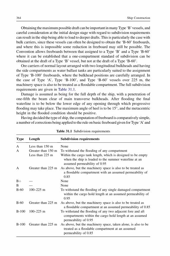
Obtaining themaximumpossible draft can be important inmanyType ‘B’vessels, andcareful consideration at the initial design stage with regard to subdivision requirementscan result in the ship being able to load to deeper drafts. This is particularly the casewithbulk carriers, since these vessels can often be designed to obtain the ‘B-60’ freeboards,and where this is impossible some reduction in freeboard may still be possible. TheConvention allows freeboards between that assigned to a Type ‘B’ and a Type ‘B-60’where it can be established that a one-compartment standard of subdivision can beobtained at the draft of a Type ‘B’ vessel, but not at the draft of a Type ‘B-60’.
Ore carriers of normal layout arranged with two longitudinal bulkheads and havingthe side compartments as water ballast tanks are particularly suited to the assignmentof Type ‘B-100’ freeboards, where the bulkhead positions are carefully arranged. Inthe case of Type ‘A’, Type ‘B-100’, and Type ‘B-60’ vessels over 225 m, themachinery space is also to be treated as a floodable compartment. The full subdivisionrequirements are given in Table 31.1.
Damage is assumed as being for the full depth of the ship, with a penetration ofone-fifth the beam clear of main transverse bulkheads. After flooding the finalwaterline is to be below the lower edge of any opening through which progressiveflooding may take place. The maximum angle of heel is to be 15�, and the metacentricheight in the flooded condition should be positive.
Having decided the typeof ship, the computationof freeboard is comparatively simple,a number of corrections being applied to the rule on basic freeboard given for Type ‘A’ and
Table 31.1 Subdivision requirements
Type Length Subdivision requirements
A Less than 150 m NoneA Greater than 150 m To withstand the flooding of any compartment
Less than 225 m Within the cargo tank length, which is designed to be emptywhen the ship is loaded to the summer waterline at anassumed permeability of 0.95
A Greater than 225 m As above, but the machinery space is also to be treated asa floodable compartment with an assumed permeability of0.85
Bþ — NoneB — NoneB-60 100–225 m To withstand the flooding of any single damaged compartment
within the cargo hold length at an assumed permeability of0.95
B-60 Greater than 225 m As above, but the machinery space is also to be treated asa floodable compartment at an assumed permeability of 0.85
B-100 100–225 m To withstand the flooding of any two adjacent fore and aftcompartments within the cargo hold length at an assumedpermeability of 0.95
B-100 Greater than 225 m As above, but the machinery space, taken alone, is also to betreated as a floodable compartment at an assumedpermeability of 0.85
364 Ship Construction

Type ‘B’shipsagainst length of ship.The length (L) is definedas 96%of the total length onthewaterline at 85%of the leastmoldeddepth, oras the lengthmeasured fromthe fore sideof the stem to the axis of the rudder stock on the waterline, if that is greater.
The corrections to the basic freeboard are as follows:
a. Flush deck correction. The basic freeboard for a Type ‘B’ ship of not more than 100 m inlength having superstructures with an effective length of up to 35% of the freeboard length(L) is increased by:
7:5ð100� LÞ�0:35� E
7
�mm
where E ¼ effective length of superstructure in meters.b. Block coefficient correction. Where the block coefficient Cb exceeds 0.68, the basic free-
board (as modified above, if applicable) is multiplied by the ratio:
Cb þ 0:68
1:36
Cb is defined in the rules as V/(L$l B$l d), where V is the molded displacement ata draft d, which is 85% of the least molded depth.
c. Depth correction. The depth (D) for freeboard is given in the rules. Where D exceeds L/15the freeboard is increased by (D � (L/15))R mm, where R is L/0.48 at lengths less than 120m and 250 at lengths of 120 m and above. Where D is less than L/15 no reduction is made,except in the case of a ship with an enclosed superstructure covering at least 0.6L amidships.This deduction, where allowed, is at the rate described above.
d. Superstructure correction.Where the effective length of superstructure is 1.0L, the freeboardmay be reduced by 350 mm at 24 m length of ship, 860 mm at 85 m length, and 1070 mm at122 m length and above. Deductions at intermediate lengths are obtained by linear inter-polation. Where the total effective length of superstructures and trunks is less than 1.0L thededuction is a percentage of the above. These percentages are given in tabular form in therules, and the associated notes give corrections for size of forecastles with Type ‘B’ ships.
e. Sheer correction. The area under the actual sheer curve is compared with the area undera standard parabolic sheer curve, the aft ordinate of which (SA) is given by 25(L/3þ 10) mmand the forward ordinate (SF) by 2SA mm. Where a poop or forecastle is of greater thanstandard height, an addition to the sheer of the freeboard deck may be made.
The correction for deficiency or excess of sheer is the difference between the actualsheer and the standard sheer multiplied by (0.75 � S/2L), where S is the total meanenclosed length of superstructure. Where the sheer is less than standard the correctionis added to the freeboard. If the sheer is in excess of standard a deduction may bemade from the freeboard if the superstructure covers 0.1L abaft and 0.1L forward ofamidships. No deduction for excess sheer may be made if no superstructure coversamidships. Where superstructure covers less than 0.1L abaft and forward of amidshipsthe deduction is obtained by linear interpolation. The maximum deduction for excesssheer is limited to 125 mm per 100 m of length.
If the above corrections are made to the basic freeboard, the final calculatedfreeboard will correspond to the maximum geometric summer draft for the vessel.
Load Line Rules 365

The final freeboard may, however, be increased if the bow height is insufficient, or theowners request the assignment of freeboards corresponding to a draft that is less thanthe maximum possible. Bow height is defined as the vertical distance at the forwardperpendicular between the waterline corresponding to the assigned summer freeboardand the top of the exposed deck at the side. This height should not be less than thevalues quoted in the Convention.
Minimum freeboards
The minimum freeboard in the summer zone is the freeboard described above;however, it may not be less than 50 mm. In the tropical and winter zones theminimum freeboard is obtained by deducting and adding respectively 1/48th of thesummer molded draft. The tropical freeboard is, however, also limited toa minimum of 50 mm. The freeboard for a ship of not more than 100 m length inthe winter North Atlantic zone is the winter freeboard plus 50 mm. For other ships,the winter North Atlantic freeboard is the winter freeboard. The minimum free-board in fresh water is obtained by deducting from the summer or tropical free-board the quantity:
Displacement in SW
4� TPCmm
where TPC is the tonnes per cm immersion at the waterline, and displacement is intonnes.
Timber freeboards
If a vessel is carrying timber on the exposed decks it is considered that the deckcargo affords additional buoyancy and a greater degree of protection against the sea.Ships thus arranged are granted a smaller freeboard than would be assigned to a Type‘B’ vessel, provided they comply with the additional conditions of assignment fortimber-carrying vessels. No reduction of freeboard may be made in ships thatalready have Type ‘A’ or reduced Type ‘B’ freeboards. The freeboards are computedas described above, but have a different superstructure correction, this beingmodified by the use of different percentage deductions given in the rules for timberfreeboards. Winter timber freeboard is obtained by adding to the summer timberfreeboard 1/36th of the molded summer timber draft. Winter North Atlantic timberfreeboard is the same as for normal freeboards, and the tropical timber freeboard isobtained by deducting from the summer timber freeboard 1/48th of the moldedsummer timber draft. The fresh water timber freeboard is determined as for normalfreeboards.
Conditions of assignment of freeboard
1. The construction of the ship must be such that her general structural strength willbe sufficient for the freeboards to be assigned. The design and construction of the
366 Ship Construction

ship must be such that her stability in all probable loading conditions is sufficientfor the freeboards assigned. Stability criteria are given in the Convention.
2. Superstructure end bulkheads. To be of efficient construction to the satisfaction ofthe Administration. The heights of the sills of openings at the ends of enclosedsuperstructures should be at least 380 mm above the deck.
3. Hatchways closed by portable covers with tarpaulins. The coamings should be ofsubstantial construction with a height above deck of at least 600 mm on exposedfreeboard and RQD and on exposed superstructure decks within 25% of the ship’slength from FP (Position 1) and at least 450 mm on exposed superstructure decksoutside 25% of the ship’s length from FP (Position 2).
The width of bearing surface for the covers should be at least 65 mm. Where coversare of wood the thickness should be at least 60 mmwith a span of not more than 1.5 m.For mild steel portable covers, the strength is calculated with assumed loads. Theassumed loads on hatchways in Position 1 may be not less than 1 tonne/square meterfor ships 24 meters in length and should not be less than 0.75 tonnes/square meter forhatchways in Position 2. Where the ship’s length is 100 m or greater the assumedloads on hatchways at Positions 1 and 2 are 1.75 and 1.30 tonnes/square meterrespectively. At intermediate lengths the loads are obtained by interpolation.
The product of the maximum stress thus calculated and the factor 4.25 should notexceed the minimum ultimate strength of the material. The deflection is limited to0.0028 times the span under these loads.
For portable beams of mild steel the assumed loads above are adopted, and theproduct of the maximum stress thus calculated and the factor 5 should not exceed theminimum ultimate strength of the material. Deflections are not to exceed 0.0022 timesthe span under these loads.
Mild steel pontoon covers used in place of portable beams are to have theirstrength calculated with the assumed loads above. The product of the maximum stressso calculated and the factor 5 should not exceed the minimum ultimate strength of thematerial, and the deflection is limited to 0.0022 times the span. Mild steel platingforming the tops of the covers should have a thickness not less than 1% of the stiffenerspacing or 6 mm if that is greater. Covers of other material should be of equivalentstrength. Carriers and sockets are to be of substantial construction and where rollingbeams are fitted it should be ensured that beams remain in position when thehatchway is closed.
Cleats are set to fit the taper of wedges. They are at least 65 mm wide, spaced notmore than 600 mm center to center, and not more than 150 mm from the hatch covers.Battens and wedges should be efficient and in good condition. Wedges should be oftough wood or equivalent material, with a taper of not more than 1 in 6, and should benot less than 13 mm thick at the toes.
At least two tarpaulins in good condition should be provided for each hatchway,and should be of approved material, strength, and waterproof. Steel bars or equivalentare to be provided to secure each section of the hatchway covers after the tarpaulinsare battened down, and covers of more than 1.5 m in length should be secured by atleast two such securing appliances.
Load Line Rules 367

4. Hatchways closed by weathertight steel covers. Coaming heights are as for thosehatchways with portable beam covers. This height may be reduced or omittedaltogether on condition that the Administration is satisfied that the safety of the shipis not thereby impaired. Mild steel covers should have their strength calculatedassuming the loads given previously. The product of the maximum stress thuscalculated and the factor of 4.25 should not exceed theminimumultimate strength ofthematerial, and deflections are limited to notmore than 0.0028 times the span underthese loads. Mild steel plating forming the tops of the covers should not be less inthickness than 1% of the spacing of stiffeners or 6 mm if that is greater. The strengthand stiffness of covers made of other materials is to be of equivalent strength.
Means of securing weathertightness should be to the satisfaction of the Administra-tion, the tightness being maintained in any sea condition.
5. Machinery space openings. These are to be properly framed and efficientlyenclosed by steel casings of ample strength. Where casings are not protected byother structures their strength is to be specially considered. Steel doors to be fittedfor access should have the sills at least 600 mm above the deck in Position 1, andat least 380 mm above the deck in Position 2. Fiddley, funnel, or machinery spaceventilator coamings on exposed decks are to be as high above deck as isreasonable.
6. Other openings in freeboard and superstructure decks. Manholes andflush scuttles in Positions 1 or 2 or within superstructures other thanenclosed superstructures should be closed by substantial weathertight covers.Openings other than those considered are to be protected by an enclosedsuperstructure or deckhouse, or companionway of equivalent strength. Doorsfor access should be of steel, and the sills should have the same heights asabove.
7. Ventilators.Should have steel coamings and where they exceed 900 mm in heightthey should be specially supported. In Position 1 ventilator coamings should beof height 900 mm above deck, and in Position 2 760 mm above deck. Ventopenings should be provided with efficient weathertight closing appliancesexcept in the case of coamings exceeding 4.5 m in height in Position 1 and 2.3 min height in Position 2, above deck.
8. Air pipes. Exposed parts of pipe should be of substantial construction. Theheight from the deck should be at least 760 mm on the freeboard deck and 450mm on superstructure decks. A lower height may be approved if these heightsinterfere with working arrangements. Permanently attached means of closingthe pipe openings should be provided.
9. Cargo ports and other similar side openings. Below the freeboard deck to befitted with watertight doors to ensure the ship’s structural integrity. Unlesspermitted by the Administration the lower edge of such openings should not bebelow a line drawn parallel to the freeboard deck at the side, which has at itslowest point the upper edge of the uppermost load line.
10. Scuppers, inlets, and discharges. Discharges led through the shell either fromspaces below the freeboard deck or from within superstructures and deckhouses
368 Ship Construction

on the freeboard deck fitted with weathertight doors should be fitted with efficientand accessible means for preventing water from passing inboard. Normally thisshould be an automatic nonreturn valve with means of closing provided above thefreeboard deck. Where the vertical distance from the summer waterline to theinboard end of the discharge pipe exceeds 0.02L the discharge may have twoautomatic nonreturn valves without positive means of closing, provided theinboard valve is always accessible. Where the distance exceeds 0.02L a singleautomatic nonreturn valve without positive means of closing may be accepted. Inmanned machinery spaces, main and auxiliary sea inlets and discharges inconnection with the operation of machinery may be controlled locally. Scuppersand discharge pipes originating at any level and penetrating the shell either morethan 450 mm below the freeboard deck or less than 600 mm above the summerwaterline should be fitted with an automatic nonreturn valve. Scuppers leadingfrom superstructures or deckhouses not fitted with weathertight doors should beled overboard.
11. Side scuttles. Below the freeboard deck or within the enclosed superstructures,side scuttles should be fitted with efficient hinged, watertight, inside dead-lights. No side scuttle should be fitted with its sill below a line drawn parallelto the freeboard deck at the side and having its lowest point 2.5% of the ship’sbreadth above the summer waterline or 500 mm, whichever is the greaterdistance.
12. Freeing ports. The minimum freeing port area (A) on each side of the ship wheresheer in way of the well is standard or greater than standard, is given, in squaremeters, by A ¼ 0.7 þ 0.035 l where l is the length of bulwark in the well and isless than 20 m, and A ¼ 0.07 l where l is greater than 20 m.
In no case need l be greater than 0.7L. If the bulwark is greater than 1.2 m in height, Ais increased by 0.004 square meters per meter of length of well for each 0.1 mdifference in height. If the bulwark is less than 0.9 m in height, A is reduced by 0.004square meters per meter of length of well for each 0.1 m difference in height. Wherethere is no sheer, A is increased by 50% and with less than standard sheer thepercentage increase is obtained by interpolation.
The lower edges of freeing ports should be as near the deck as practicable. Two-thirds of the freeing port area is required to be provided in the half of the well nearestthe lowest point of the sheer curve, where the deck has sheer. Openings in thebulwarks are protected by bars spaced approximately 230 mm apart. If shutters arefitted, these should be prevented from jamming.
13. Protection of crew. Efficient guard-rails or bulwarks of minimum height 1 meterare to be fitted on all exposed parts of freeboard and superstructure decks. Alower rail may be permitted by the Administration. The maximum verticalspacing between deck and lower rail is 230 mm, and between other rails is380 mm.
Satisfactory means should be provided for protection of crew in getting to and fromtheir quarters and other parts used in the working of the ship.
Load Line Rules 369

Special conditions of assignment for Type ‘A’ ships
1. Machinery casings. To be protected by an enclosed poop or bridge of standard height, ordeckhouse of equivalent strength and height. The casing may be exposed if there are nodoors fitted giving access from the freeboard deck, or if a weathertight door is fitted andleads to a passageway separated from the stairway to the engine room by a secondweathertight door of equivalent material.
2. Gangway and access. An efficiently constructed fore and aft gangway should be fitted atthe level of the superstructure deck between poop and midship bridge or deckhouse, orequivalent means such as passages below deck. If houses are all aft, satisfactoryarrangements should be made to allow crew to reach all parts of the ship for workingpurposes.
3. Hatchways. All exposed hatchways on freeboard and forecastle decks or on top ofexpansion trunks are to be provided with efficient watertight covers of steel or equivalentmaterial.
4. Freeing arrangements. Should have open rails fitted for at least half the length of theexposed parts of the weather deck, with the upper edge of the sheer strake being kept as lowas possible. Where superstructures are connected by trunks, open rails should be fitted forthe whole length of the exposed parts of the freeboard deck in way of the trunk.
Further reading
International Conference on Load Lines, 1966. IMO publication (IMO 701E), 2005 edition.
370 Ship Construction

32 Structural fire protection
Chapter OutlineRequirements 371‘A’, ‘B’, and ‘C’ class divisions 372Openings in fire protection divisions 373Protection of special category spaces 375Fire protection arrangements in high-speed craft 375Further reading 375Some useful websites 376
Of the requirements of the International Conventions for the Safety of Life at Sea,those having a particular influence on ship construction are the requirements relatingto structural fire protection. Varying requirements for vessels engaged in internationalvoyages are given for passenger ships carrying more than 36 passengers, passengerships carrying not more than 36 passengers, cargo ships, and tankers.
Requirements
Ships carrying more than 36 passengers are required to have accommodation spacesand main divisional bulkheads and decks that are generally of incombustible materialin association with either an automatic fire detection and alarm system or an auto-matic sprinkler and alarm system. The hull, superstructure, and deckhouses aresubdivided by ‘A’ class divisions into main vertical zones, the length of which on anyone deck should not exceed 40 m. Main horizontal zones of ‘A’ class divisions arefitted to provide a barrier between sprinklered and nonsprinklered zones of the ship.Bulkheads within the main vertical zones are required to be ‘A’, ‘B’, or ‘C’ classdivisions depending on the fire risk of the adjoining spaces and whether adjoiningspaces are within sprinkler or nonsprinkler zones.
Passenger vessels carrying not more than 36 passengers are required to have thehull, superstructure, and deckhouses subdivided into main vertical zones by ‘A’ classdivisions. The accommodation and service spaces are to be protected either by allenclosure bulkheads within the space being of at least ‘B’ class divisions or only thecorridor bulkheads being of at least ‘B’ class divisions, where an approved automaticfire detection and alarm system is installed.
Ship Construction. DOI: 10.1016/B978-0-08-097239-8.00032-5
Copyright � 2012 Elsevier Ltd. All rights reserved.

Cargo ships exceeding 500 gross tonnage are generally to be constructed of steel orequivalent material and to be fitted with one of the following methods of fireprotection in accommodation and service spaces:
l ‘Method Ic’. All internal divisional bulkheads constructed of noncombustible ‘B’ or ‘C’class divisions and no installation of an automatic sprinkler, fire detection, and alarmsystem in the accommodation and service spaces, except smoke detection and manuallyoperated alarm points, which are to be installed in all corridors, stairways, and escaperoutes.
l ‘Method IIc’. An approved automatic sprinkler, fire detection, and fire alarm system isinstalled in all spaces in which a fire might be expected to originate, and in general there isno restriction on the type of divisions used for internal bulkheads.
l ‘Method IIIc’. A fixed fire detection and fire alarm system is installed in all spaces inwhich a fire might be expected to originate, and in general there is no restriction onthe type of divisions used for internal bulkheads except that in no case must the areaof any accommodation space bounded by an ‘A’ or ‘B’ class division exceed 50 squaremeters.
Crowns of casings of main machinery spaces are to be of steel construction andinsulated. Bulkheads and decks separating adjacent spaces are required to haveappropriate A, B, or C ratings depending on the fire risk of adjoining spaces. Cargospaces of ships of 2000 gross tonnage or more are to be protected by a fixed gas fire-extinguishing system or its equivalent unless they carry bulk or other cargoesconsidered by the authorities to be a low fire risk. Cargo ships carrying dangerousgoods are subject to special fire protection precautions.
In the construction of tankers, particular attention is paid to the exteriorboundaries of superstructures and deckhouses that face the cargo oil tanks.Accommodation boundaries facing the cargo area are insulated to A60 standard,no doors are allowed in such boundaries giving access to the accommodation,and any windows are to be of non-opening type and fitted with steel covers if inthe first tier on the main deck. Bulkheads and decks separating adjacent spaces ofvarying fire risk are required to have appropriate A, B, and C ratings within theaccommodation space. For new tankers of 20,000 tons deadweight and upwardsthe cargo tanks’ deck area and cargo tanks are protected by a fixed deck foamsystem and a fixed inert gas system (see Chapter 26). Tankers of less than2000 tons deadweight are provided with a fixed deck foam system in way of thecargo tanks.
‘A’, ‘B’, and ‘C’ class divisions
‘A’ class divisions are constructed of steel or equivalent material and should becapable of preventing the passage of smoke and flame to the end of a one-hourstandard fire test. A plain stiffened steel bulkhead or deck has what is known as anA-O rating. By adding insulation in the form of approved incombustible materials tothe steel an increased time is taken for the average temperature of the unexposed sideto rise to 139 �C above the original temperature or not more than 180 �C at any one
372 Ship Construction

point above the original temperature during the standard fire test. The ‘A’ classdivision rating is related to this time as follows:
Class Time (min)A-60 60A-30 30A-15 15A-0 0
Figure 32.1 shows typical steel divisions with typical proprietary non-asbestos fiber-reinforced silicate board insulation. ‘B’ class divisions are those that are constructedas to be capable of preventing the passage of flame to the end of half an hour of thestandard fire test. Various patent board materials are commonly used where ‘B’ classdivisions are required and there are two ratings B-0 and B-15. These relate to theinsulation value such that the average temperature of the unexposed side does not risemore than 139 �C above the original temperature and at any one point more than225 �C above the original temperature when the material is subjected to the standardfire test within the following times:
Class Time (min)B-15 15B-0 0
‘C class divisions are constructed of approved incombustible materials but do notneed to meet any specified requirements relative to passage of smoke and flame nortemperature rise.
The standard fire test referred to is a test in which a specimen of the division witha surface area of not less than 4.65 square meters and height or length of 2.44 m isexposed in a test furnace to a series of time–temperature relationships, defined bya smooth curve drawn through the following points:
At end of first 5 minutes 538 �CAt end of first 10 minutes 704 �CAt end of first 30 minutes 843 �CAt end of first 60 minutes 927 �C
Some typical examples of fire divisions are given in Table 32.1 for a passenger shipcarrying more than 36 passengers.
Openings in fire protection divisions
Generally, openings in fire divisions are to be fitted with permanently attached meansof closing that have the same fire-resisting rating as the division. Suitable
Structural fire protection 373
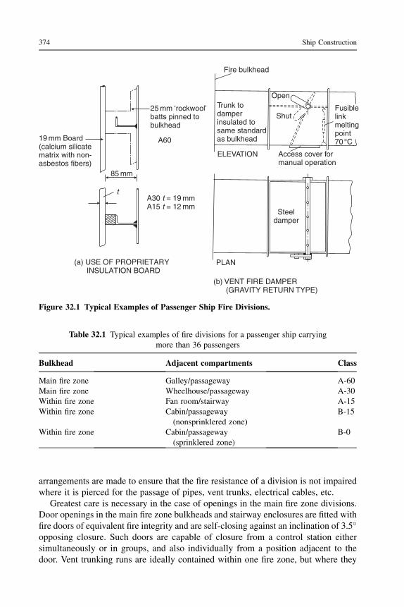
arrangements are made to ensure that the fire resistance of a division is not impairedwhere it is pierced for the passage of pipes, vent trunks, electrical cables, etc.
Greatest care is necessary in the case of openings in the main fire zone divisions.Door openings in the main fire zone bulkheads and stairway enclosures are fitted withfire doors of equivalent fire integrity and are self-closing against an inclination of 3.5�opposing closure. Such doors are capable of closure from a control station eithersimultaneously or in groups, and also individually from a position adjacent to thedoor. Vent trunking runs are ideally contained within one fire zone, but where they
Table 32.1 Typical examples of fire divisions for a passenger ship carryingmore than 36 passengers
Bulkhead Adjacent compartments Class
Main fire zone Galley/passageway A-60Main fire zone Wheelhouse/passageway A-30Within fire zone Fan room/stairway A-15Within fire zone Cabin/passageway
(nonsprinklered zone)B-15
Within fire zone Cabin/passageway(sprinklered zone)
B-0
19 mm Board(calcium silicatematrix with non-asbestos fibers)
25 mm ‘rockwool’batts pinned tobulkhead
A60
85 mm
A30 = 19 mmA15 = 12 mm
tt
(a) USE OF PROPRIETARYINSULATION BOARD
t
Open
ShutFusiblelinkmeltingpoint70°C
Fire bulkhead
Trunk todamperinsulated tosame standardas bulkhead
ELEVATION Access cover formanual operation
Steeldamper
PLAN
(b) VENT FIRE DAMPER(GRAVITY RETURN TYPE)
Figure 32.1 Typical Examples of Passenger Ship Fire Divisions.
374 Ship Construction

must pass through a main fire zone bulkhead or deck a fail-safe automatic-closing firedamper is fitted within the trunk adjacent to the bulkhead or deck. This usually takesthe form of a steel flap in the trunk, which is held open by a weighted hinge secured byan external fusible link. The flap must also be capable of being released manually andthere is some form of indication as to whether the flap is open or closed (seeFigure 32.1).
Protection of special category spaces
A special category space is an enclosed space above or below the bulkhead deckused for the carriage of motor vehicles with fuel for their own propulsion in theirown tanks and to which passengers have access. Obvious examples are the garagespaces in ro-ro passenger ferries and vehicle decks in ro-ro cargo ships. Such spacescannot have the normal main vertical fire zoning without interfering with theworking of the ship.
Equivalent protection is provided in such spaces by ensuring that the horizontaland vertical boundaries of the space are treated as main fire zone divisions and anefficient fixed fire-extinguishing system is fitted within the space. This takes the formof a fixed-pressure water-spraying system, generally in association with an automaticfire detection system. Special scupper arrangements are provided to clear the deck ofthe water deposited by the system in the event of a fire to avoid a drastic reductionin stability.
Fire protection arrangements in high-speed craft
The IMO High-Speed Craft Code (HSC Code) recognizes the use of lightweightconstruction materials such as aluminum alloy and fiber-reinforced plastics that havea lesser fire rating than steel. Consequently, that Code has applied a new approach tofire insulation to that taken by SOLAS for conventional steel ships. The HSC Codehas introduced the concept of a ‘fire-restricting material’, which may be a combus-tible material or combination of combustible materials provided it can comply witha prescribed fire test limiting heat release, smoke production, and spread of flame.Also introduced is the concept of a ‘fire-resisting division’ to prevent flame spreadfrom one compartment to another within a prescribed time, which is related toa passenger evacuation time for the craft. A fire-resisting division can be constructedfrom noncombustible material, fire-resisting material, or a combination of both.
Further reading
International Code of Safety for High Speed Craft (HSC Code). IMO publication (IMO-1185E), 2000 edition.
Structural fire protection 375

SOLAS Consolidated Edition. Chapter II-2, Part B: Fire safety measures for passenger ships;Part C: Fire safety measures for cargo ships, IMO publication (IMO 110E), 2009.
Testing for fire safety in modern marine designs, The Naval Architect, October 2004.
Some useful websites
www.imo.org/home See ‘Safety’, then ‘Fire protection, fire detection and fire extinction’ forhistory of SOLAS fire protection requirements, summary of requirements, fire testrequirements, relevant publications, etc.
376 Ship Construction

Part Five
Ship Structure
Introduction
Ships are the largest, mobile man-made structures in the world. The largest ships arecomparable with major buildings, but have additionally to withstand enormous forcesfrom wind and waves. Their structural arrangements are therefore of great impor-tance. Because in most cases ships have to earn by carrying cargo, their structure notonly has to be strong, it must also be as light as possible.
The structure of a ship is based on flat and curved steel plate panels, with primaryand secondary stiffening. The complete hull structure has to fulfill several importantrequirements. These include:
l Maintaining watertight integrityl Separating internal spaces, for example cargo, fuel oil, ballast waterl Resisting forces on the ship, in particular from waves.
The structure also has to conform to the hull shape dictated by hydrodynamics, i.e. theperformance in terms of speed and seakeeping specified by the hull designer.
Both the forces on the ship and the capability of the structure have some uncer-tainty, which must be allowed for in the design. The structure may suffer fromchanges in material properties over the life of the ship. Some causes of structuralfailure are hard to predict, for example fatigue and corrosion. The quality of work-manship can also vary considerably.
Basic structural arrangements
The structure of a ship is based primarily on panels, both flat and curved. These arethe building blocks of the structure and also provide a convenient breakdown of thestructure into units during ship construction (see Chapter 14).
The basic components of the panels are steel plates and steel profiles. The platesform the panels and the profiles are used to provide stiffening to prevent the platesdeforming when subjected to forces.
There is a specific terminology for the structural components.Plating forms the main structural elements of the ship, which are:
l Hull bottom plating, inner and outer bottoml Hull side plating

l Hull deck platingl Internal bulkheadsl Internal decks.
Stiffening for the various panels includes:
l Longitudinals that run along the bottom plating and provide significant strength. There maybe a keel in the form of a longitudinal center-line girder.
l Deck girders, also longitudinal, which again contribute to the longitudinal strength of theship.
l Stringers, running longitudinally on the side plating, and where required along the inner sideplating for a double-hull ship.
l Frames, which run vertically up the side plating.l Floors, which are deep transverse frames on the bottom plating.l Deck beams, which support the deck transversely.
Note
Throughout this part of the book a number of requirements relating to the spacing andscantlings of various structural members are given. These are intended only asexamples, which were taken from Lloyd’s Register rules at the time of writing andwere introduced only to give the student an idea of the variation in dimensions andscantlings found within the ship structure. Other classification society requirementsmay differ, but basically the overall structure would have the same characteristics. Itshould be borne in mind that owner’s additional requirements and the nature ofa particular trade can result in ships having greater scantlings and additionalstrengthening to the minimum indicated in the following chapters.
174 Ship Structure

Ship Construction
Seventh edition
D. J. EyresM.Sc., F.R.I.N.A.Formerly Lecturer in Naval Architecture, Department of Maritime Studies,Plymouth Polytechnic, (now University of Plymouth)
G. J. BruceM.B.A, F.R.I.N.A., MSNAME.Formerly Professor of Shiprepair and Conversion,School of Marine Science and Technology, Newcastle University
AMSTERDAM l BOSTON l HEIDELBERG l LONDON l NEW YORK l OXFORDPARIS l SAN DIEGO l SAN FRANCISCO l SINGAPORE l SYDNEY l TOKYO
Butterworth-Heinemann is an imprint of Elsevier

Butterworth-Heinemann is an imprint of ElsevierThe Boulevard, Langford Lane, Kidlington, Oxford, OX5 1GB
225 Wyman Street, Waltham, MA 02451, USA
First published 1971
Second edition 1978Third edition 1988
Fourth edition 1994Fifth edition 2001
Sixth edition 2007Seventh Edition 2012
Copyright � 2012 Elsevier Ltd. All rights reserved.
No part of this publication may be reproduced or transmitted in any form or by any means, electronic
or mechanical, including photocopying, recording, or any information storage and retrieval system,without permission in writing from the publisher. Details on how to seek permission, further
information about the Publisher’s permissions policies and our arrangement with organizations suchas the Copyright Clearance Center and the Copyright Licensing Agency, can be found at our website:
www.elsevier.com/permissions
This book and the individual contributions contained in it are protected under copyright by thePublisher (other than as may be noted herein).
NoticesKnowledge and best practice in this field are constantly changing. As new research and experience
broaden our understanding, changes in research methods, professional practices, or medicaltreatment may become necessary.
Practitioners and researchers must always rely on their own experience and knowledge in evaluatingand using any information, methods, compounds, or experiments described herein. In using such
information or methods they should be mindful of their own safety and the safety of others, includingparties for whom they have a professional responsibility.
To the fullest extent of the law, neither the Publisher nor the authors, contributors, or editors, assumeany liability for any injury and/or damage to persons or property as a matter of products liability,
negligence or otherwise, or from any use or operation of any methods, products, instructions, or ideascontained in the material herein.
British Library Cataloguing in Publication Data
A catalogue record for this book is available from the British Library
Library of Congress Number: 2012936092
ISBN: 978-0-08-097239-8
For information on all Butterworth-Heinemann publications
visit our website at store.elsevier.com
Printed and bound in the United States
12 13 14 15 10 9 8 7 6 5 4 3 2 1

Acknowledgments
The authors are grateful to the following firms and organizations who were kindenough to provide information and drawings from which material for the book wasextracted:
Appledore Shipbuilders LtdBlohm and Voss, A.G.British Maritime TechnologyBritish Oxygen Co. LtdE.I. Du Pont De Nemours & Co. LtdESAB ABIrish Shipping LtdMacGregor-Navire International A.B.Mitsubishi Heavy Industries LtdOcean Steamship Co. LtdShell Tankers (UK) LtdShipping Research Services A/SHugh Smith (Glasgow) LtdStone Manganese Marine LtdWavemaster International
Lloyd’s Register of Shipping also gave permission to refer to various requirements oftheir ‘Rules and Regulations for the Classification of Ships’.
D.J.E. and G.J.B.

Preface
This text is designed as an introductory text for students of marine sciences andtechnology, including those following BTEC National and Higher National programsin preparation for careers at sea and in marine related industries. The subject matter ispresented in sufficient depth to be of help to more advanced students on under-graduate programs in Marine Technology and Naval Architecture, as well as thosepreparing for the Extra Master examination. Students converting from other disci-plines for higher degrees will also find the information useful. Other studentsfollowing professional courses in shipbuilding will also find the book useful asbackground reading.
Many professionals from other disciplines, including law, insurance, accounting,and logistics joining the businesses will find the basic technical information on shipconstruction of value.
Considerable changes have occurred in ship design and shipbuilding practice withthe introduction of new technology, and this book attempts to present current shipyardtechniques without neglecting basic principles. Shipbuilding covers a wide field ofcrafts and, with new developments occurring regularly, it would be difficult to coverevery aspect fully within the scope of a single textbook. For this reason furtherreading lists are given at the end of most chapters, these being selected from books,transactions, and periodicals that are likely to be found in the libraries of universitiesand other technical institutions.
In this edition the authors have also added a listing of some useful websites at theend of most chapters relating to the subject matter of the chapter. Those listed containfurther information, drawings, and photographs that complement the text and/or addfurther knowledge to the subject. Some of the websites that are referenced also dealwith regulations that apply to ships and their construction. The rapid development ofavailable information makes it impossible to provide a completely up-to-date set ofwebsites. Therefore, there is space for students to add further websites recommendedby their tutors or that they may have found informative. However, it is important toconsider the sources of information on any new sites to confirm their currency andvalidity.

Subject Index
Note: Page references followed by “f” indicate figure, and by “t” indicate table.
A‘A’ brackets, 258–260, 261fconstruction of, 260
‘A’ class divisions, 372–373A60 standard, 372Aframax, 13Aft end structure, 249–252, 258, 262Aft peak, 251f, 259fAft peak bulkhead, 208–209, 213, 218After end structure, 273After perpendicular (AP), 11–12Air pipes, 319, 368–369Air-conditioning, 31, 126, 345–346Alkyd resin, 334–337‘Alternative tonnages’, 20Aluminumalloy, 53–55, 56f, 65alloy sandwich panels, 57alloy tests, 65alloying elements, 55extrusions, 54, 97fiber-reinforced composites (FRCs), 58–59fire protection, 57high speed ferries, 54numeric designation, 55production, 54–57riveting, 55–57superstructure, 53–54, 57
Aluminum-to-steel connections, 332fAmidships, 11–12Anchor stowage, 248Annealing, 48Annual surveys, 41Antifouling paints, 338–339Antifouling systems, 337–339A-O rating, 372–373
Assembly, 149–151, 153fAssembly plate parts listing, 133fAssembly plate parts nesting, 133fAssociation of West European
Shipbuilders, 361–362Association of Western European Shipyards
(AWES), 7–8Atmospheric corrosion, 328, 330Automatic arc welding, 88fAutomatic welding with cored wires, 86Auxiliary steering gear, 256–258Awning deck, 19–20, 19f
B‘B’ class divisions, 373‘B-60’ freeboards, 364Backstep weld method, 107, 108fBalanced rudders, 254Ballastcapacity, 24, 29, 177, 184, 214–216, 320dirty system, 316pumping and piping arrangements,315–318
Bar keel, 175, 176fBarge-carrying ships, 21Base line, 12–13Bending stress, 68–73Beamextreme, 12–13knees, 138–140molded, 12–13
Bending moments, 20–21, 29, 31, 256, 297in seaway, 68wave, 70f
Bending stresses, 68–73ship as beam, 71

Bending stresses (Continued )strength deck, 71–73
Bilge, 126blocks, 162, 163fkeel, 197–198, 198fpiping arrangement, 315–318, 317fpumping, 315–318scuppers, 318suctions, 316wells, 180, 319
Bimetallic corrosion, 330–331, 330tBitumen, 334–337Blast cleaning, 339–340Blockassembly, 152building, 162, 163f
Block coefficient correction, 365Boiler bearers, 187Boot topping region, 342Bottom girders, 269Bottom structuredouble, 177–184, 179f, 181f, 182fkeels, 175–177, 176fmachinery seats, 184–187single, 177, 178f
Bowdoors, 307–308ramps, 308steering arrangements, 248thrust units, 248
Bracket floors, 180–183Brackets, tank side, 192f, 193, 194fBreadth, 5, 12–13
see also Beam‘Breast hooks’, 243, 245fBridge structures, 238Brine, 346–348coolers, 349traps, 348–349, 350f
Brittle fracture, 75–76Brittleness, 61Buckling, 76–78Building berths, 122–123Building docks, 122–123, 163f, 170–171Building hall, 154–155, 171Building slipway, 162Bulbous bows, 243–244, 245fBuckling, 76–78Bulk carriers, 13, 23–26, 25f
bottom structure of, 184, 185fbulkhead stool, 213fsingle shell side block unit, 149fsingle side skin midship section, 200f, 201f
Bulk carrier single shell side block unit, 149fBulkhead stool, 210, 213fBulkheads, 207–213, 271watertight, 211f, 212f
Bulwarks, 235–237, 236fconstruction, 235–237
Buoyancy, 67–68Butterfly’ rig, 297–299Butt welds, 190, 197–198Butts, 189
see also Butt welds
C‘C’ class divisions, 373Cabin module, 154fCamber, 12–13Canals, 5Capesize bulk carriers, 293–294Capesize ships, 13Car carriers, 26, 27fCargoaccess, 307–308and ballast tanks, 342pumps, 321restraint, 312–314tank washing, 324–325
Cargo handling equipment, 23Cargo lifting
see also Shipboard cranesCargo ports, 368–369Cargo shipsdry, 17–23watertight bulkheads spacing,
208–209Cargo tankprotection, 321–324purging and gas freeing, 324ventilators, 321washing, 324–325
Cathodic protection, 333–334Cavitation, 331Centre line girder, 250fChain locker, 244–245construction of, 244–245, 246f
Chain pipes, 244–245, 246f
378 Index

Charpy impact test, 63–65, 64fChemical additions (steel), 47Chemical tankers, 275f, 276Chlorinated rubber, 334–337Classification societies, 6damage repairs, 43hull planned maintenance scheme, 43Lloyd’s Register, 38–39periodical surveys, 41–43rules and regulations, 38ship operating in ice, 40structural design programs, 40–41tests for hull materials, 63–65weld tests, 114
Clean water ballast, 29, 272Coal tar, 334–337Coastal tanker, 266fCode for the Construction and Equipment
of Ships Carrying DangerousChemicals in Bulk (BCH Code), 276
Cold frame bending, 144Collision bulkhead, 208–209, 213Community of European Shipyards
Associations (CESA) contract form,7–8
Compensated gross tonnage (CGT),361–362
Computer-aided design (CAD), 130–134Computer-aided manufacturing (CAM),
130–134Consumables, 114Containerguides, 313flashing, 312ships, 15, 21, 22f, 202fstackers, 313f
Contracts, 7–8Controllable pitch propellers, 260–262Conveyor, 136–138Corrosion, 331electrochemical nature of, 328–330due to immersion, 328nature and forms, 327–333
Corrosion allowance, 333Corrosion cell, 329fCorrosion control, 333–337cathodic protection, 333–334paints, 337protective coating, 334–337
Corrosion-inhibiting paints, 334–337Corrosion-resistant steels, 50Corrugated bulkheads, 210Cranes, 120Crew protection, 369Cross ties, 164Crude oil carrier, 320–321Cruise ships, 31, 262Cruiser stern, 250fCurved panel, 151Cutting, 98–101gas, 98gouging, 100laser, 100–101metal, 99fplasma-arc, 98–100water jet, 101
Cutting machines, plate profile, 138–140
DDamage repairs, 43Deadrise, 12–13Deadweight, 12–13Deck, 226–229beams, 105, 229cranes, 294construction, 230fgirders, 220, 223, 226, 229, 269loads, 226, 229longitudinals, 269plating, 226–228sheathing, 228fstiffening, 229supports, 227ftransverses, 269
Deck girders, 269Deckhouses, see Superstructures and
deckhousesDeep tanks, 214–216construction, 216, 217ftesting, 216
Depth correction, 365Derrick rigs, 297–305, 299fforces in, 300–303, 302finitial tests and re-tests of, 304–305
Designconcept, 3–4contract, 3–4one-off, 6–7
Index 379

Design (Continued )preliminary, 3–5preparation of, 3–4spiral, 3, 4f
Det Norske Veritas (DNV), 51Dimensions, 5, 11–13, 14fDirect line cargo piping arrangements, 322fDisplacement, 5Docking surveys, 41–42Docksbuilding, 122–123, 170–171floating, 171–172
Doorswatertight, 21–23, 41, 213–214, 215f,368–369
weathertight, 214, 240, 308, 318,368–369
Double-bottom compartments, testing, 184Double-hull oil tanker, 268fDouble-hull tanker, 28ferection sequence for, 156f
Draft, 5, 14fextreme, 12–13molded, 12–13
Drag chains, 168, 170Drilling machines, 140Dry cargo bulk carrier, 156fDuct keels, 177Ductility, 61Dye penetrant testing, 112
EEconomic criteria, 3–4Egg box structure, 149–151construction, 105
Elastic limit, 62Elastomers, 51Electric arc welding, 84–93, 85fElectric furnaces, 46Electric podded propulsors, 262–264advantages of, 262
Electrochemical corrosion, 328–331Electro-gas welding, 94Electro-slag welding, 94, 95fElephant’s foot type cargo lashing, 312,
313fElevators, 311fEnd launchesarresting arrangements, 168–170, 169f
building slipway, 162launching sequence, 168launching ways and cradle, 164–165lubricant, 165releasing arrangements, 165–168
Engine seats, 186fEntrance, 12–13Epoxy resins, 334–337Erection welding sequences, 110Erosion, 331Expansion trunks, 28f, 265, 370Extreme beam, 12–13Extreme depth, 12–13Extreme dimensions, 12–13Extreme draft, 12–13Extrusion, 54–55
FFairing ship lines, 126–131, 132fFatigue failures, 76Feeder ships, 15Fiber-reinforced composites (FRCs),
58–59Fillet welds, 105, 107Fire doors, 374–375Fire protection, 57in cargo ships, 372in high-speed craft, 375
Fire resistance, 373–375Fire zone bulkheads, 374–375Fitting out basin, 121, 123fFitting out berth, 121, 148–149Flame planers, 140Flare, 12–13Flat panel, 151Flat plate keel, 175, 176f, 189Floating docks, 171–172Floating production, storage, and offloading
vessels (FPSOs), 274Floating storage units (FSUs), 274Floors, 180Flush deck correction, 365Flux-cored wires (FCAW), 86Folding covers, 232–235Fore end construction, 242fFore end structure, 243f, 272–273deep tank, 272–273forepeak, 273ice strengthening, 273
380 Index

Forecastle, 237, 241, 244–245Forty-foot equivalent unit (FEU), 13Forward perpendicular (FP), 11–12Frame bending, 143–146, 145fcold frame bending, 144robotics, 144–146section profilers, 144
Framing, 191–193longitudinal, 193transverse, 192–193, 192f
Freeboard, 12–13Freeboard computation, 363–366minimum freeboard, 366timber freeboards, 366
Freeboard corrections, 365–366Freeing arrangements, 370Freeing ports, 235, 368–369Friction stir welding, 96–97, 97fFully pressurized tanks, 282Fully refrigerated tanks, 283
GGalvanic corrosion, 330–331, 330tGalvanic series, 330, 330tGangway and access, 370Gap presses, 141fGarboard strake, 176f, 178fGascutting, 98shield arc welding, 89–93welding, 82–84, 83f
Gas carriersgeneral arrangement, 287–288Lloyd’s classification, 288–289
Gas-freeing fans, 324Gas-shielded arc welding process,
89–93GAZ Transport membrane system, 283Gearless carriers, see Capesize bulk
carriers; Panamax carriersGeneral arrangement, 6General cargo shiperection sequence for, 155fmasts on, 294–295midship section, 199f
General service pipes, 318–319General service pumping, 318–319Glass fiber-reinforced plastic (GRP), 58Goal-based standards, 38
Gouging cutting, 100Grade E steel, 268tGreen material, 148, 158Greenfield, 120–121Gross tonnage (GT), 359–360Ground ways, 162, 165Guillotines, 140Gunwale, rounded, 190–191, 191t, 268t
HHalf beams, 229Half block model, 128Half breadth, 12–13Half siding of keel, 12–13Hand cleaning, 340Handymax, 13Handysize, 13Hardness, 61Hatch, 229–235coamings, 232covers, 232–235, 233f, 234fopening, 231f
Hatchways, 271, 370Hawse pipes, 247f, 248Heating, see Heating, ventilation, and air-
conditioning (HVAC)Heating, ventilation, and air-conditioning
(HVAC), 345Heat-line bending, 142–143Heat treatment of steels, 48Heavy lifting, 300
see also Patent Stulken derricksHigh speed craft, 204fHigher tensile steels, 267–268High-pressure water blasting, 340High-speed craft, 31–33fire protection in, 375types, 32f
Hogging, 68Hold ventilation, 347fHorizontal girders, 216Hovercraft, 18f, 31–33Hull form, 6, 11–12, 23Hull planned maintenance scheme, 43
IIceclasses, 40strengthening, 195–197
Index 381

IMO High-Speed Craft Code (HSC Code),375
IMO International Gas Carrier Code,280–282
independent tanks, 281integral tanks, 280–281internal insulation tanks, 281membrane tanks, 281secondary barrier protection, 282, 282tsemi-membrane tanks, 281
IMO length, 11–12Impact tests, 63–65‘Impingement attack’, 331Impressed current antifouling systems,
337Impressed current systems, 334, 335fIndependent tanks, 281Independent Type A tanks, 283–286Independent Type B tanks, 286Inert gas system, 324Inner bottom plating, 180Insulation, 349, 350f, 372A60 standard, 372
Integral tanks, 280–281Intermediate surveys, 41Internal deck access ramps, 309fInternal insulation tanks, 281International Air Pollution Prevention
Certificate, 357International Association of Classification
Societies (IACS), 37–38, 357International Certificate of Fitness for the
Carriage of Dangerous Chemicals inBulk, 276
International Code for the Constructionand Equipment of Ships CarryingDangerous Chemicals in Bulk(IBC Code), 276
cargo tank types, definition, 276International Conference on Tonnage
Measurement was convened by theIMO in 1969, 359
International Convention for the Preventionof Pollution from Ships (MARPOL),324, 356
convention, 267, 271tankers, 15, 29–30
International Convention for the Safety ofLife at Sea (SOLAS), 1974, 356, 375
International Convention on Load Lines ofShips, 1966, 356
International Convention on the Control ofHarmful Antifouling on Ships, 2001,338
International Convention on TonnageMeasurement, 1969, 356
International Conventions for the Safety ofLife at Sea, 371
International Labour Organization (ILO)Convention, 305
International Load Line ConventionCertificate, 357
International Maritime Organization(IMO)
oil tanker categories, 15organization of, 355relationship with classification societies,
357relationship with national authorities,
356–357work of, 355–356
International Sewage Pollution PreventionCertificate, 357
International Tonnage Certificate, 357,360–361
Inverse curve, 144In-water surveys, 42ISO hole, 313–314Isomerized rubber, 334–337
J‘Jack-knifing’, 303Joining ship sections afloat, 158–159
KKeel blocks, 162Keel rake, 12–13Keels, 175–177, 176fKilled steels, 47, 86Kort nozzle, 262Kvaerner-Moss spherical tank, 287f
LLaser cutting, 100–101Laser welding, 95–96Lashing points, 313fLaunching, 161–172, 166farresting arrangements, 168–170, 169f
382 Index

building docks, 170–171cradle, 164–165, 169fdeclivity, 162, 164, 170drag chains, 168, 169f, 170end, 162–170floating docks, 171–172lubricant, 165marine railways, 172releasing arrangements, 165–168, 167fsequence, 168ship lifts, 171side, 170slewing arrangements, 167ftriggers, 165–168ways and cradle, 164–165
Lengthoverall (LOA), 11–12between perpendiculars (LBP), 11–12
Lighter aboard ship (LASH), 21Lines plan, 126–128, 127fLiquefied gas carriers, 284fLiquefied natural gas (LNG), 280Liquefied natural gas ships, 283–286independent Type A tanks, 283–286independent Type B tanks, 286membrane tanks, 286semi-membrane Type B tanks, 286
Liquefied petroleum gas (LPG), 279–280Liquefied petroleum gas ships, 282–283fully pressurized tanks, 282fully refrigerated tanks, 283semi-pressurized (or semi-refrigerated)tanks, 282–283
Liquid methane carrier, 285fLloyd’s classification, 288–289Lloyd’s length, 11–12Lloyd’s Register (LR), 38–39, 49–50, 55,
76, 78, 110, 208, 229–232classification symbols, 39
Load Line Convention, 357Load line rulesfreeboard assignment conditions,366–370
freeboard computation, 363–366Local stresses, 73–75Loftwork, 128–130scale lofting, 10:1, 130
Longitudinal bottom framing, 182f, 183Longitudinal deck framing, 226, 269
Longitudinal shear forces, 68Longitudinal side framing, 193Lubricant, 165
MMacGregor-Navire International AB
‘Rotoloader’, 311MacGregor-Navire International AB
‘Stackcell’ system, 313–314Machinerycasings, 370positions, 20–21, 364, 366–369seats, 184–187space openings, 368–369
Magnetic particle testing, 112Mangles, 137Manual welding electrodes, 86, 87fManufacture of steels, 46–47Marine Environmental Protection
Committee (MEPC), 355–356Marine pollution prevention, 355–356Marine railways, 172Maritime Administration (MARAD),
USA, 7Maritime Safety Committee (MSC),
355–356Mast construction, 297Masts, 294–297Matrix assemblies, see Egg box structureMechanical planers, 140Mechanical ventilation, 345Mega-blocks, 158Membrane systems, 288fMembrane tanks, 281, 286Merchant Shipping Act (1894), 30Metal cutting, 99fMetal inert gas (MIG) welding, 89–93,
91fMid-deck tanker, 29–30Midship sectionbulk carrier, 200f, 201fcargo ship, 192, 199fcontainer ship, 202frefrigerated cargo ship, 348fro-ro ship, 203fcoastal tankers, 266f
Mild steel, 267Millscale, 137, 329fMinor assembly, 151
Index 383

Modern rudders, 254Mold, 58–59Mold loft, 130Molded beam, 12–13Molded depth, 12–13Molded dimensions, 12–13Molded draft, 12–13Monitoring Ship Stresses at Sea, 78Multi-product tankers, 321
NNesting plate, 133fNet tonnage (NT), 360Neutral axis, 69–71New Panamax ships, 15Nondestructive testing, 112–114Normalizing, 48Norwegian Shipbuilders Association and
Norwegian Shipowners Association, 7Notation, 39–40Notchductility, 75–76tough steel, 75–76
Numerical flame cutting control system,139f
OOECD, 361–362Oil Pollution Act, 1990 (OPA 90), 29Oil tankers, 13, 15, 26–30, 28flongitudinal framing of, 270f
Oiltight hatchways, 271Oleo-resinous, 334–337Open floors, 175, 177Open hearth process, 46Open shelter deck, 20Open water stern, 23Outfit modules, 152–154Oxyacetylene flame, 340Oxyacetylene, 82–84, 98Oxygen process, 47
PPaint systems on ships, 341–342below waterline, 342superstructures, 342waterline or boot topping region, 342
Painting ships, 339–342cargo and ballast tanks, 342
paint systems on ships, 341–342surface preparation, 339–340temporary protection during building, 341
Paints, 334–337corrosion protection by, 337
see also Protective coatingsPanama Canal Authority, 361Panama Canal limits, 15Panama Canal tonnages, 361Panamax, 13, 15Panamax carriers, 293–294Panamax ships, 15Panel assemblies, 122f, 133, 151–152Panting, 73–74additional stiffening for, 195arrangements forward, 196f
Parallel middle body, 12–13Passenger ship fire divisions, 374f, 374tPassenger Ship Safety Certificate, 356–357Passenger ships, 30–33superstructures, 238–240watertight bulkhead spacing, 209
Patent Stulken derricks, 300Payment schedule, 8Periodical surveys, 41–43Photogrammetry, 158Perpendicular after, 11–12, 14f, 126Perpendicular forward, 11–12, 126Pickling, 340Pig iron, 45–47Piggyback covers, 232–235Pillars, 220–223, 221fconstruction, 220–223small, 223small solid, 222fspacing of hold, 220
Pipe module, 150fPiping arrangements, 320–325Planing machines, 140Plasma welding, 93, 93fPlasma-arc cutting, 98–100Platebutts, 108–110, 189edge preparation, 106fhandling in machine shops, 138preparation, 135–138profilers, 144rolls, 141seams, 108–110, 189
384 Index

Plate preparation, 135–138heating, 137part preparation, 138–143plate leveling rolls (mangles), 137priming paint, 137shot-blasting, 137stockyard, 136
Polyurethane resins, 334–337Pontoon covers, 232–235Poop structure, 238Poppets, 162, 164–165, 166fPortable decks, 311–312Post-Panamax ships, 15Pounding, 74Pounding region, additional stiffening in,
183–184Powder cutting, 98Prefabrication, 147–148Pre-MARPOL tankers, 15Presses, 140–141Primer, 342Priming paint, 137Proof stress, 63Propeller post, 252–254Propellers, 260–262controllable pitch propellers, 260–262nozzle, 263fshrouded propellers, 262
Propulsive performance, 5Protective coatings, 334–337Pumping and piping arrangementsin cargo ships, 315in tankers, 320–325
Purchase, of new vessel, 6–7
QQuarter access ramps, 310fQueen Mary 2, 249, 264Quenching, 48
RRabbet, 128, 252–254Racking, 73Radiographic testing, 110, 112, 114Raised quarter deck, 17–19Rakeof keel, 12–13of stem, 12–13
Ramps, 308–309
‘Reefer ships’, 349Refrigerated cargo ship, 348fRefrigerated cargo stowage, 346Refrigerated container ships, 349–351Refrigeration, 346–348Register length, 11–12Rimmed steels, 47, 86Ring main cargo piping arrangements, 323fRise of floor, 12–13, 164Riverside layout, traditional, 119fRiveting aluminum, 55–57Robotics, 107, 144–146Roll-on roll-off (ro-ro) vessels, 21–23, 22f,
203f, 307stern ramps in, 308
Rudders, 254–256, 255fbearing, 256, 257fconstruction, 254pintles, 254–256stock, 256trunk, 256
Run, 12–13
SSacrificial anode systems, 333Safe working load (SWL), 294Safety convention, 355–357Sagging, 68Sampson posts, 294–297Scale lofting, 10:1, 130Scantling, 19–20, 229Scissor lift, 312Scrieve board, 229Scuppers, 318inlets, and discharges, 368–369
Sea inlets, 319–320, 320fSeams, 189Secondary barrier protection, 282, 282tSection machining, 123f, 138–143Section preparation, 135–138Section profilers, 144Segregated ballast tanks (SBTs), 267Self-polishing copolymer (SPC) antifouling
paints, 338Semi-membrane tanks, 281Semi-membrane Type B tanks, 286Semi-pressurized tanks, 282–283Semi-refrigerated tanks, 282–283Service speed, 6
Index 385

Shaft bossing, 258–260, 261fconstruction of, 260
Shaft tunnel, 218, 219fconstruction, 218
Sheaves, 300–303Sheer, 12–13Sheer correction, 365Sheerstrake, 190Shellbutts, 108–110, 189expansion, 128, 129fforming, 142fplating, 189–204, 190fbilge keel, 197–198, 198fbottom, 189–190framing, 191–193grades of steel for, 191local strengthening of, 195–197seams, 108–110, 189side, 190–191tank side brackets, 193, 194f
Shell plating, three-dimensionalrepresentations, 128
Shelter deck, 19–20Shiparresting arrangements, 168–170, 169fas beam, 71building process, 122fclassification, operating in ice, 40design, 3–5drawing office, 125–128lifts, 171product model, 131–134, 132freleasing arrangements, 165–168, 167fspiral, 4fstresses, 78structure assembly, 147–159types, 18f
Ship drawing office, 126–128lines plan, 126–128, 127floftwork followed, 128–130shell expansion, 128, 129fshell plating, three-dimensionalrepresentations, 128
Ship lifts, 171Ship openings, 368–369Ship product model, 132fShip types, 364tShipboard cranes, 293–294
Shipbuilders Association of Japan (JSA),7, 361–362
Shipbuilding process, 122f, 135Shipyard layout, 119–123, 123fmodern large, 121f
Shipyard planning, decisions involved,121
Shipyard replanning, decisions involved,121
Shot-blasting, 137, 340Shrouded propellers, 262Sidedoors, 309–311girders, 183–184launching, 170loaders, 309–311scuttles, 368–369
Single bottom structure, 177construction, 166f
Single product carrier, 320–321Single pull covers, 232–235Single-hull bulk carrier, block erection for,
157fSlag-shielded processes, 84–89Slewing ramp, 309, 310fSliding ways, 164–165, 170Slipways, 119–120, 162Small waterplane area, twin hull craft
(SWATH), 18f, 31–33, 32fSolid plate floors, 180–184, 269Sounding pipes, 319Spacing of watertight bulkheads:cargo ships, 208–209passenger ships, 209
Spar deck, 19–20, 19fSpecial category space, protection of, 375Special surveys, 42–43Special trade passenger (STP) ships, 31‘Spectacle frame’, 260Spurling pipes, 244–245Stability, 5Standard fire test, 373Steelcastings, 52chemical addition to, 47construction, 372corrosion-resistant, 50forgings, 52grade, 46
386 Index

heat treatment of, 48high tensile, 50Lloyd’s requirement for mild, 191tmanufacture, 46–47sandwich panels, 50–51sections, 48, 49fshipbuilding, 49
Steering gear, 256–258Stem rake, 12–13Stern, 241–243construction, 252doors, 307–308, 308fframe, 252–254, 253framps, 308f, 310ftube, 258, 259f
Stiffening, 297in mast and heavy derricks, 298f
Stockyard, 136Strain, 61–62Strength deck, 71–73Stress, 61–62corrosion, 331relieving, 48and strain relationship, 104f
Structural design programs, 40–41Structural fire protection, 371–375requirement, 371–372special category space, 375see also Fire protection
Stud welding, 88–89, 90fSubassembly, 151Submerged arc welding, 86–88Submerged turret loading (STL) system,
274Suez Canal Authority, 361Suez Canal limits, 16Suez Canal tonnages, 361Suezmax, 13Superstructure correction, 365Superstructures, 273–274Superstructures and deckhouses,
237–240bridge structures, 238effective, 238, 239fforecastle, 237passenger ship, 238–240poop structure, 238weathertight doors, 240
Surface effect ships (SESs), 31–33
Surface preparation for paint, 339–340Syncrolift, 171
TTack weld, 105Tankcleaning, 30, 271side brackets, 193, 194ftop, 177, 180, 193, 210, 223, 349
Tank spaces, construction in, 268–269bottom girders, 269deck girders, 269floors and transverses, 269longitudinal framing, 269
Tanker construction materials, 267–268higher tensile steel, 267–268mild steel, 267
Tankerscargo piping arrangements in, 320–325,322f
cargo pumping arrangements in,320–325
Tempering, 48Template drawing, 130Tensile strength, 61, 63Tensile test, 63Testingdeep tanks, 216derrick rigs, 304–305double-bottom compartments, 184material, 61–65rudder, 254tanks, 272watertight bulkheads, 213
Thermit welding, 96Three island type, 17, 19–20Timber freeboard, 366Toilet module, 154fTonnage, 12–13, 20, 356–357, 359–360compensated gross tonnage (CGT),361–362
gross tonnage, 359–360measurement for, 360–361net tonnage, 360
Topside tanks, 218Torsion, 73, 74fToughness, 61Transom stern, 251fTransverse framing, 269
Index 387

Transverse stresses, 73Transverse webs, 193, 195, 268–269, 268f,
273Transversely framed double bottom,
180–183Trial speed, 6Tributyltin compounds (TBTs), 338Triggers, 165–168Tumblehome, 12–13Tungsten inert gas welding, 89Turret deck, 24Tween deck height, 12–13Twenty-foot equivalent unit (TEU), 13‘Two-pack paints’, 334–337Type ‘A’ ships, 363–365special conditions of assignment, 370
Type ‘B’ ships, 363–365
UUltimate strength, 61, 63Ultra-large container ships, 15Ultra-large crude carrier (ULCC), 13Ultrasonic inspection, 114Unbalanced rudders, 254Union purchase rig, 303forces in, 304f
Unit:assembly, 151–152erection, 154–158, 155f, 156f, 157f
VVehicle lashing, 312Ventilation, 345–346fire damper, 374f
Ventilators, 368–369Vertical shear and longitudinal bending, in
still water, 67–68, 69fVertical stiffeners, 210Very large crude carrier (VLCC), 13Vinyl resins, 334–337Virtual reality, 134Visual inspection of welds, 112
WWater blasting, 340Water jet cutting, 101Watertight bulkheads:construction, 209–210corrugated, 212fplain, 211fspacing, 208–209testing, 213
Watertight doors, 213–214, 215fWave bending moments, 68, 70fWave piercer, 18f, 31–33Weather deck, 26, 226–229, 235, 346, 370Weathertight doors, 240Weathertight vehicle ramp, 307–308Weldingautomation, 105–107classification society tests and, 114distortion, 107electric arc, 84–93, 85felectro-gas, 94electro-slag, 94, 95fand faults, 110, 111fflux and, 82–88, 94friction stir, 96–97, 97fgas, 82–84, 83fand inspection, 113flaser, 95–96and nondestructive testing, 112–114practice, 103–105sequences, 107–110, 108fand testing, 110thermit, 96
Wing in ground effect craft (WIG), 18fWire model, 131Wood ceiling, 177, 180
YYield point, 63
ZZinc-rich paints, 334–337
388 Index