1 adaptive truncated harq aided layered video … · adaptive truncated harq aided layered video...
TRANSCRIPT

1
Adaptive Truncated HARQ Aided Layered VideoStreaming Relying On Inter-Layer FEC Coding
Chuan Zhu, Yongkai Huo, Bo Zhang, Rong Zhang, Mohammed El-Hajjar and Lajos Hanzo, Fellow, IEEESchool of ECS, University of Southampton, UK.
Email: {cz12g09, yh3g09, rz, bz2g10, meh, lh}@ecs.soton.ac.uk, http://www-mobile.ecs.soton.ac.uk
Abstract— Inter-layer forward error correction coding (IL-FEC) constitutes an effective unequal error protection (UEP)scheme conceived for transmitting layered video over wirelesschannels. In contrast to traditional UEP schemes, it operates byembedding extra information concerning the base layer (BL) intothe enhancement layers (ELs) without requiring extra transmis-sion resources. The received EL packets assist in the decodingof the BL in order to reduce the distortion of the reconstructedvideo. The optimum scheduling of the IL-FEC coded layeredvideo streaming in a truncated HARQ (THARQ) aided system isan open problem. Hence in this treatise, we conceive an adaptiveTHARQ (ATHARQ) algorithm for finding the most appropriatescheduling of the IL-FEC coded layered video packets for thesake of minimizing the video distortion under the constraint of agiven total number of transmission time slots. Furthermore, wedevelop a method of on-line coding-rate optimization algorithmfor our IL-ATHARQ transmission scheme, in order to find thebest FEC code rate distribution among the video layers thatresults in the lowest possible video distortion. When using arecursive systematic convolutional (RSC) code, our simulationresults show that the proposed rate-optimized IL-ATHARQsystem outperforms the traditional THARQ transmission schemeby about 5.3 dB of Eb/N0 at a peak signal-to-noise ratio (PSNR)of 38.5 dB. Viewing the improvements in terms of the videoquality, 2.5 dB of PSNR improvement is attained at an Eb/N0
of 15 dB.
I. INTRODUCTION
The wireless channel is subject to impairments imposedboth by the noise and fading. Thus the task of transmittingvideo contents to users equipped with various terminals is achallenging one both in terms of source coding and transmis-sion techniques [1]. Layered video coding [2] is a widely usedscheme conceived for handling this heterogeneous networkingproblem. By providing multiple layers of different importance,layered video coding is capable of supporting progressivereception of video steams, depending both on the prevalentchannel conditions and on the hardware requirements of theindividual users. More specifically, the most important layeris referred to as the base layer (BL), while the enhancementlayers (ELs) are capable of providing additional video qual-ity refinements during instances of higher channel qualities.Hence the popular video standards [3]–[7] are capable ofsupporting layered video coding. For example, H.264 providespartitioned video coding [6] for generating multiple layers (orpartitions) of different error-sensitivity. The multiview profile(MVP) [4] developed by the moving picture expert group(MPEG) generates different encoded views as different layers.The scalable compression based extension of the H.264/AVC
The financial support of the EU’s Concerto project, of the EPSRC underthe auspices of the India-UK Advanced Technology Centre (IU-ATC) and thatof the ERC’s Advanced Fellow Grant is gratefully acknowledged.
standard [6] is referred to as scalable video coding (SVC)[5], [6], which generates an encoded stream containing mul-tiple interdependent layers, where some of the layers canbe discarded in case of network-congestion for example, inorder to tailor the bit-rate according to the specific user-requirements and/or channel quality. At the time of writing, thehigh efficiency video coding (HEVC) scheme, also known asthe H.265 standard [3], is being further developed to create anextension referred to as scalable high-efficiency video coding(SHVC) [8], [9] in order to support scalability.
Hybrid automatic retransmission request (HARQ) aidedsystems rely on the combination of two error correctionmechanisms that are capable of improving the reliability oftransmissions: automatic retransmission request (ARQ) andforward error correction (FEC), where the original signalsare retransmitted upon requests, when the signals cannot beflawlessly decoded by the FEC decoders. In Type-I HARQ,the transmitter retransmsits the original packet upon receptionof a negative acknowledgment (NACK) feedback. In orderto provide a more reliable decision concerning the originalpacket and to achieve a diversity gain, the best approach atthe receiver is to combine the various corrupted retransmittedsignals according to the maximal ratio combining (MRC)principle, which is carried out by adding the Log-LikelihoodRatios (LLRs) of several packet replicas. This approach is alsoreferred to as Type-I HARQ relying on Chase Combining(CC) [10]. In Type_II HARQ, incremental redundancy (IR)generated from the original packet in form of additional paritybits is transmitted instead of the original packet upon receivinga NACK feedback. Finally, all the information is appropriatelycombined at the receiver. This scheme is often referred to asType_II HARQ with IR.
Due to the delay-constraints of near-real-time video trans-mission systems, only the employment of truncated HARQ(THARQ), relying on a limited number of retransmissionsis realistic. The energy efficiency of THARQ protocols de-signed for a single-user link or assisted by relay stations wasconsidered in [11]. The closed-form analytical expressionsof the achievable throughput, of the average packet delayand of the packet loss rate was provided in [12], wherethe maximization of the system throughput was also carriedout. The performance analysis of a wireless network usingadaptive modulation and coding combined with THARQ-CCat the data link was presented in [13]. The transmission ofcontrol messages using adaptive modulation and coding wasconsidered in [14] in the scenario of voice over InternetProtocol (VoIP) services supported by THARQ. However, theassociated video characteristics had not been addressed in theaforementioned THARQ schemes. As a further advance, a

2
video transmission system was proposed and analyzed in [15],which relied both on THARQ and selective combining, as wellas on rate-compatible punctured convolutional (RCPC) codesfor transmission over fading channels. A finite-state Markovmodel was used for representing the Rayleigh fading channels.An improved video quality was achieved by the proposedscheme at a limited delay. Layered video has been consideredfor transmission using HARQ schemes in either unicast ormulticast scenarios [16]–[20]. The authors of [16] presenteda theoretical analysis as well as rich experimental results forcharacterizing both unicast and multicast scenarios for trans-mission over packet-erasure channels, while the authors of[17]–[20] provided solutions for multicast systems transmittinglayered video using various HARQ schemes.
The transmission of layered video can be protected byunequal error protection (UEP) [21]. In [22], the cross-layer design of FEC schemes is investigated by using UEPRaptor codes at the application layer (AL), and UEP RCPCcodes at the physical layer (PHY) for the prioritized videopackets, which are prioritized based on their contribution tothe received video quality. The authors of [23] introducedan APP/MAC/PHY cross-layer architecture that improves theperceptual quality of delay-constrained scalable video trans-mission. Furthermore, an online QoS-to-QoE mapping tech-nique is proposed in [23] for quantifying the QoE reductionimposed by each video layer using both the ACK history anda variety of perceptual metrics. The authors of [24] studied thechannel-dependent adaptation capability of SVC by conceivinga solution for transmission over an orthogonal frequency divi-sion multiplexing (OFDM) based broadband network relyingon cross-layer optimization. The FEC protected UEP may beclassified into two categories, namely the packet-level schemes[25]–[32] and bit-level schemes [33]–[40]. The packet-levelcontributions [25]–[32] usually employ hard decoded FECcodes for mitigating the packet loss events at the applicationlayer [41], while the bit-level ones operate at the physical layerand rely on soft decoded FEC codes for correcting bit-errorsin wireless scenarios [42]. Traditional UEP schemes designedfor layered video transmission only handle the different impor-tance of separate video layers by assigning different-rate FECcodes to them. By contrast, the recent contributions [28], [31],[32], [38], [40] explored the dependencies amongst the layersand conceived UEP schemes by exploiting this sophisticatedfeature. Specifically, the unsuccessful decoding of the BL willinstruct the video decoder to discard all the ELs depending onit, regardless whether they have or have not been successfullydecoded. Naturally, this course of action wasted the transmitpower assigned to the dependent layers. Thus we proposedin our previous work [40] a bit-level inter-layer coded FEC(IL-FEC) scheme that embeds the BL into the FEC codedELs, so that the reception of the BL can be improved withthe aid of the ELs using soft decoding. In our subsequentwork [43] we conceived a sophisticated on-line real-time videodistortion estimation technique, which is suitable for diversechannel conditions and system configurations. More explicitly,in [43] we proposed an on-line code rate optimization methodfor minimizing the video distortion.
A range of UEP schemes have been conceived for HARQ
[44]–[52] in order to improve the video quality of layeredvideos. The authors of [44] proposed UEP by appropriatelysharing the bitrate budget between the source and channelencoders based on either the minimum-distortion or on theminimum-power consumption criterion. In [50], [51], UEPwas achieved by assigning each video layer a different re-transmission limit. Another stream of contributions [44], [46]–[49] adopted the so-called limited-retransmission based pri-ority encoding transmission (PET) scheme [53], where UEPis achieved by varying the source block-length across thedifferent source layers, while keeping the FEC-dcoding block-length fixed. This allows the PET to have a packetizationscheme that ensures that the source layers of an FEC-codedblock are dropped according to their significance, commencingby dropping the least significant one first.
Against this background, in this treatise, we conceive anadaptive THARQ (ATHARQ) transmission scheme in supportof IL-FEC coded layered video for minimizing the videodistortion under the constraint of a given total number of trans-mission time slots. In our previous work [40], the transmissionenvironment of THARQ was not considered. Furthermore, themerits of IL-FEC schemes have not been investigated in thecontext of THARQ transmission schemes. However, the packetscheduling schemes should be carefully designed by ensuringthat instead of the sequential packet transmissions assumed in[40], we have to exploit the specific characteristics of each IL-FEC coded packet. Furthermore, we develop a method of on-line optimization for our IL-ATHARQ transmission scheme, inorder to find the most appropriate FEC code rate distributionamong the video layers that reduces the video distortion. Type-I HARQ relying on Convolutional Codes (CC) is used forsimplicity, because our focus is on the design of the schedulingschemes. Our proposed technique is significantly differentfrom the existing contributions, such as the PET frameworkof [53], as detailed below. Firstly, our transmission schemeis proposed for wireless channels, while most contributionson PET [53] operate at the packet-level and consider theBinary Erasure Channel (BEC). Secondly, IL-FEC typicallyrelies on bit-level FEC decoders using soft decoding, such asa Recursive Systematic Convolutional (RSC) code, while PETemploys hard-decoded codes, such as the family of (N , k)block codes.
Against this background, the rationale and novelty of thispaper is summarized as follows.
1) We intrinsically amalgamated IL-FEC coding with theTHARQ-aided transmission of layered video. We con-ceived an ATHARQ transmission scheme for adaptivelyscheduling the IL-FEC coded video layer packets forminimizing the video distortion under the constraint ofa certain total number of transmission time slots.
2) We develop a method of on-line optimization for ourIL-ATHARQ transmission scheme, in order to find theoptimal FEC code rate distribution, sharing among thevideo layers that results in a reduced video distortion.Quantitatively, about 2.5 dB of PSNR video qualityimprovement may be observed at an Eb/N0 of 15 dB,over the traditional THARQ benchmaker. Alternatively,we will demonstrate that an Eb/N0 reduction of about

3
������
������
���
���
���
���
���
���
���
���
������
������
π
π
z1,pz01
Decoders H.264 SVC
L1
L0
Encoders H.264 SVC
x0
z01
Le(x1)
Decod. 0
z1,p
z0
z0,pFECLe(x0)
Puncturer 0
x0
x1
x0
x01x1
x1,p
x0,px0 x0,pEncoder
FEC
EncoderFEC
Puncturer 1
x1,p
Mod
x01
L1
L0
CRC
CRC
CRC−1
Adaptive
Retransmission
Controller
Channel
Estimator
z0,py0 y0,p
y1,py01
MRC
MRC
Buffer
r1
r0
Demodx1
La(x0)
Decod. 1FEC
CRC−1
z0
La(x1)
π−1
Fig. 1: Block diagram of the proposed ATHARQ-IL-FEC coded SVC H.264/AVC coded video system, where r0 and r1
represent the code rates for FEC encoder 0 and 1, respectively.
5.3 dB at a PSNR of 38.5 dB can be achieved.
The rest of this paper is organized as follows. Section IIdetails the IL-FEC transmitter and receiver model, as wellas the proposed ATHARQ protocol along with the benchmarkschemes we used in this treatise. The algorithm of our IL-ATHARQ retransmission controller is described in SectionIII, followed by the details of the coding-rate optimizationof the IL-ATHARQ system in Section IV. The performanceof our IL-ATHARQ scheme as well as the rate-optimized IL-ATHARQ scheme using a RSC codec are compared to thebenchmarks in Section V using different video sequences,followed by characterizing both the effects of the delay aswell as well of the channel quality prediction errors on theattainable system performance. Finally, we conclude in SectionVI.
II. SYSTEM OVERVIEW
Here we introduce the IL-ATHARQ-aided inter-layer videotransceiver shown in Fig. 1. The system consists of two majorparts: the inter-layer FEC (IL-FEC) protected video codecand the retransmission control protocol. Firstly, the formerone is introduced based on [40], where the inter-layer FECarchitecture is described in detail. We will briefly describeboth the IL-FEC transceiver architecture, as well as the IL-ATHARQ protocol in this section.
A. Transmitter Model
The original video sequence is firstly encoded into a scalablevideo stream by invoking the SVC extension of H.264 [6]. Thecompressed video stream consists of the layers L0, L1,... Ln
with the dependency of L0 ⇐ L1 ⇐ . . . ⇐ Ln, where eachitem on the right of the⇐ symbol depends on all the items tothe left of it. To utilize the n-th layer for successful decoding,the decoder has to invoke the information from all the previous(n− 1) layers. For simplicity of illustration, only the pair oflayers L0 and L1 are used in our description of IL-FEC, whereL0 is the BL and L1 is the EL.
As shown in Fig. 1, each layer of the SVC encoded videois protected by the Cyclic Redundancy Check (CRC) encoder.Then each layer is encoded using their individual FEC code,typically an RSC code. Since each layer is allowed to haveits own specific code-rate, the FEC encoded layers are passedthrough their individual puncturer, which may have differentpuncturing rates. We assume that the punctured layers haveFEC code rates of r0 and r1, respectively. For layer L0 theinput bit sequence x0 is encoded and punctured in order toproduce the parity bits x0p, and for layer L1 the parity bitsx1p.
As part of the IL-FEC mechanism, the systematic part ofthe encoded layer L0, namely x0, is interleaved and thenembedded into the systematic part x1 of L1, using the bit-wiseXOR operation, producing the bit sequence x01. In the case

4
that L0 and L1 are different in length, the solution detailed in[40] may be invoked. Then the systematic bits and the paritybits of the BL are concatenated. Similarly, the EL, whichcontains the systematic bits and parity bits of the originalEL are also concatenated. For each time slot, the adaptiveretransmission controller picks the packets from one of thetwo layers and transmits them using BPSK over the wirelesschannel, which is modeled as an uncorrelated Rayleigh-fadedchannel.
B. Receiver Model
At the receiver, the likelihood of the demodulated bits isidentified. If L0 is received, the demodulated sequence consistof y0 and y0p, which represent the likelihood of the systematicinformation x0 and that of the parity information x0p for L0. IfL1 is received, the demodulated sequence consist of y and y1p,corresponding to x01 and x1p. Then the identified likelihoodinformation is combined with that of the information alreadystored in the corresponding buffer, using maximum ratiocombining (MRC). Let z′ be the likelihood before combining,and z afterwords. Then we have z0 = z′0+y0, z0p = z′0p+y0p,z01 = z′01 + y01 and z1p = z′1p + y1p.
After updating the buffers, the decoder carries out the IL-FEC decoding process. The pair of FEC decoders shown inFig. 1 invokes the BCJR algorithm [54] to produce the extrin-sic information for x0 and x1, given the a priori informationof their systematic bits and parity bits.
At the beginning of the decoding process, the FEC decoder0 of Fig. 1 generates the extrinsic information Le(x0) usingthe accumulated parity-bit-related information z0,p and thesystematic-bit-related information Lapr(x0). Since the FECdecoder 1 has no information to contribute initially, decoder0 uses z0 directly from the buffer as Lapr(x0). Given the ex-trinsic information, we can obtain the a posteriori informationby Laps(x0) = Le(x0) + Lapr(x0). The temporary decodingresult x0 is obtained by making a hard decision concerningLaps(x0). The subsequent CRC checker will check, whetherwe have x0 = x0 and if so, then Laps(x0) will be replaced bythe perfect LLR of x0. Then the interleaved Laps(x0) and z01
together will provide the a priori information of Lapr(x1) =Laps [π (x0)] � z01 for the FEC decoder 1, where π (�) rep-resents the interleaving-based permutation, while π−1 (�) thecorresponding deinterleaving function. Furthermore, given thebits u1 and u2, the ’boxplus’ operation � is defined as follows:
L (u1 ⊕ u2) = L(u1) � L(u2)
= log1 + eL(u1)eL(u2)
eL(u1) + eL(u2)
. (1)
For the second decoding phase, given the a priori in-formation Lapr (x1) of x1 and the a priori informationLapr (z1,p) of its parity bits, the FEC decoder 1 of Fig.1 generates the extrinsic information Le(x1). In turn thefunction π−1 (Le(x1) � z01) will provide part of the a prioriinformation for x0, so that the FEC decoder 0 is supplied withthe improved a priori information π−1 (Le(x1) � z01) + z0
for the systematic bits. Again, the a posteriori information is
generated by Laps(x1) = Le(x1) +Lapr(x1), upon which thehard decision yielding x1 will be carried out and the CRCchecker of Fig. 1 will be invoked to check its correctness.
By iteratively repeating the above two decoding phases, thedecoder exploits the information embedded in the EL L1 forthe sake of assisting the decoding of the BL L0, withoutaffecting the performance of the L1 transmission, as longas L0 is successfully decoded. The iterations are terminated,when either the CRC of all the layers indicates success, or theaffordable maximum number of iterations has been reached.In this treatise we set the maximum number of iterations toT = 2.
C. Major Assumptions and Transmission Protocol
Again, for the sake of limiting the delay imposed, weconsider limited-delay THARQ as our transmission technique.In our scenario we map each layer to a single packet, whichalso correspond to a single network abstraction layer unit(NALU), since we adopted the SVC profile of the H.264video codec. The packets corresponding to the different layersare likely to have different lengths of bits, depending on thelengths of the NALUs generated by the SVC codec.
The traditional THARQ transmission protocol conceivedfor the FEC coded video layers is shown in Fig. 2(a). TheBL is transmitted first, followed by the ELs. Each layeris transmitted a maximum number of n times, regardless,whether or not it is correctly received. However, accordingto the dependency between the video layers, there is no needto transmit the ELs, if the BL is lost. Therefore it is sub-optimum to assign the same retransmission limit to eachlayer. Thus we adapt the traditional THARQ by defining atotal maximum retransmission limit for a specific video slice.Explicitly, for a total of n transmissions, the BL is allowedto have a higher number of transmissions than the EL. Thisplausible prioritization principle may be readily extended toan arbitrary number of layers, where the less dependent layersare granted more transmission opportunities than the moredependent layers.
With the introduction of IL-FEC coding into the THARQaided SVC coded video steam, the constraints imposed maybe relaxed, because the IL-FEC coded layers of higher de-pendencies may have sufficient information concerning thelayers of lower dependencies and hence they may be capableof recovering them, even they were incorrectly recoveredduring the previous transmissions. As a result, it may in factbecome wasteful to complete the recovery of the BL beforetransmitting the ELs. Hence we have to carefully considerthe choice of transmission limits for each layer. The totalnumber of transmissions dedicated to a specific video sliceremains the same as defined previously for fair comparison.The philosophy of this scheme is illustrated by a specificexample in Fig. 2(b).
We set out to improve the THARQ regime introduced above,which relies on the CRC check result of the decoded layers.In the traditional regime, the transmitter only knows whetherthe current layer has or has not been successfully recovered.However, it has no quantitative knowledge about the specific

5
������
������
���
���
��������
��������
����
����
����
transmition limit reached for layer i
ACKNAK NAK
...
...
(a)
(b)
(c)
NAK NAK
...
ACK
Layer i Layer i Layer i Layer i+1
Layer i+1 Layer i+2Layer i Layer i
Layer i+1 Layer i+2Layer i
NAK i ACK i
NAK i+1
CSI
CSI
CSI
CSI
Fig. 2: THARQ schemes conceived for scalable video trans-mission: (a) pure THARQ (b) IL-FEC aided THARQ whereeach video layer has a different retransmission limit (c)proposed IL-FEC aided adaptive THARQ()
grade of degradation imposed on the unsuccessfully decodedlayers in the buffer, if any. Similarly, the transmitter has noknowledge of the next transmission’s contribution towardsthe successful decoding of the video slice. With the goal ofimproving the performance, we set out to estimate both andhence to make better-informed decisions. Therefore in ournew regime, the receiver has to provide a feedback for thetransmitter concerning the CRC result, as well as additionallyhas to feed back the channel state information (CSI) of boththe most recent transmission and of the next transmission.
In reciprocal channels typically encountered in Time Divi-sion Duplex (TDD) systems, the CSI of the next transmissioncan be acquired by appending pilot symbols to the reverse-direction ACK/NAK feedback, which allows us to estimatethe CSI and assuming that the coherence-time is less than30 ms [55], use it for predicting the channel of the nexttransmission. Owing to using this low-complexity zero-orderprediction, a prediction error may be introduced at this stage.At the reception of a packet, the receiver sends a feedbackmessage to the transmitter, which includes the CRC resultsof the layers of interest, plus the estimated CSI of thisspecific transmission. The latter one assists the transmitter inrectifying the previous CSI prediction error at the transmitter,and as a benefit, this measure prevents error propagation inthe subsequent prediction process. As shown in Fig. 2(c), thetransmitter becomes capable of estimating the contribution ofeach possible transmission at the receiver, hence intelligentlycontrolling the retransmission process by maximizing thevideo quality after the next transmission attempt.
Indeed, the new scheme introduces overheads in terms ofrequiring extra bandwidth for accommodating the feedbackchannel. However, the HARQ feedback only requires a fewbits for conveying the CRC flag of the layers queuing in thebuffer as candidates for transmission, as it will be detailed inSection III. Hence we may readily assume that this does not
impose a heavy burden on the feedback channel and assumefurthermore that it is transmitted without any errors. Bycontrast, the channel estimate feedback is more error-sensitive,because it is a floating-point number and thus it requires morebandwidth. Consequently it may not be justifiable to assumeperfect feedback reception, since the CSI feedback may besubject to channel impairments. Since the CSI feedback isused for predicting the channel of the next transmission, wewill take into account this factor by considering the CSIimpairments to be modeled by extra additive noise and asbeing part of the additive prediction error, which will bedetailed in Section III.
As mentioned, each video layer is packaged into a singleNALU and can be transmitted over a single channel instance.By contrast, when the video layers of high-resolution se-quences are represented by more bits, each video layer may bepackaged into several NALUs and transmitted over differentchannel instances. In that case, advanced channel estimationtechniques [56], [57] may be adopted for acquiring the channelestimates for the sake of predicting the video qualities, whichis beyond the scope of this treatise.
III. ADAPTIVE TRUNCATED HARQ TRANSMISSION
In this section, we will describe our adaptive truncatedHARQ aided IL-FEC coded video streaming scheme, whichis used in the “Adaptive Retransmission Controller” block ofFig. 1.
As described at the end of Section II-C, our adaptivetransmission algorithm aims for minimizing the reconstructedvideo distortion at the receiver by carefully choosing thesequential order of transmitting the different video layers,given the total number of transmissions. Again, the wirelesschannel is assumed to impose uncorrelated block-fading be-tween different time slots, which remains constant for a time-slot and then it is independently faded for the next time-slot. However, the above-mentioned TDD-related reciprocitystill allows us to exploit the correlation of the forward andreverse links for typical packet-lengths that are shorter thanthe coherence-time. Nonetheless it is impossible to predict allthe channel information for all the time slots, let alone tofind a globally optimal transmit schedule depending on thepredicted CSI information. Instead, we conceive an adaptivealgorithm, which is sub-optimal but practical and seeks toachieve the minimization of the reconstructed video distortionfor the next single transmission only, given the predictionof the forthcoming channel condition obtained by using theprotocol described in Section II-C.
In order to characterize the behavior of the receiver seen inFig. 1 relying on the proposed algorithm, a classic RSC codecis used as the FEC code. However, the employment of ourproposed techniques is not limited to the RSC codec.
Before introducing the adaptive retransmission control algo-rithm, let us define the symbols to be used in our discussionas follows:• NT : limit of the total number of transmission time slots
(TS);• NL: total number of video layers;

6
Start of
Transmission
No Yes
Estimation of
Estimation of Estimation of
Transmit Transmit
Update
SNR for
Update
SNR for
NoYes
No
Yes
End
Yes
No
No
Estimation of
No
Yes
Decision over
en(d0), en(d1)
en(d0) < en(d1) ?
L0 L1
L0 L1
L1 recovered?
en(d1), en(d2) en(d2), en(d3)
n = 0
n = n + 1 n = n + 1
n reached limit? n reached limit?
L0 recovered?
L0 recovered?
en(d0), en(d1), en(d2)
L0, L1
Decision over L1, L2 Decision over L0, L1, L2 Decision over L2, L3
Fig. 3: Adaptive THARQ algorithm for the Adaptive Retrans-mission Controller
• |hn|: the amplitude of the channel at TS n, 1 ≤ n ≤ NT ;• An = |hn|2;•∣∣∣hn∣∣∣: the prediction of |hn| as described in Section II-C;
• εi: the video distortion due to the corruption or absence oflayer i, which is measured using the peak signal-to-noiseratio (PSNR), 0 ≤ i < NL;
• SNRn: the NL-element vector, which represents theSNR values of the signals in the receiver buffers afterthe n-th transmission. In other words, SNRn,i, which isthe i-th element of SNRn, represents the SNR of thesignals in the receiver buffer as defined in Section II-B,1 ≤ n ≤ NT , 0 ≤ i < NL;
• SNRn (·): the NL-element vector, which represents thepredicted value of SNRn, depending on both SNRn−1,as well as on the channel conditions and on the schedulingdecisions, etc.;
• `i: the length of the bitstream of layer i, 0 ≤ i < NL;• R: the overall coding rate of the system;• r: the vector including the FEC coding rates of all the
layers, where ri is the coding rate of layer i, 0 ≤ i < NL;• D = {d1, d2, . . . , dNL
}: the decision-set including allthe possible choices concerning which particular layer to
transmit. The decision vector dk has NL binary elements,
where dk,i is defined as dk,i =
{1
0
k = i
k 6= i, 0 ≤ i <
NL, 0 ≤ k < NL, which means that the k-th layer ischosen for transmission;
• Dn: the actual decisions adopted for transmitting at TSn, where we have Dn ∈ D;
• pn,i (dk): the packet error ratio (PER) of layer Li at TS n,using decision dk, when layer Li−1 is correctly decoded.
The scheduling procedure of the adaptive retransmission con-troller is shown in Fig. 3. Each time the algorithm considersa number of video layers, for making decisions, as shown inthe dashed boxes of Fig. 3.
In order to generalize the scheduling process, the conceptof a decision window can be introduced, which contains thelayers to be chosen by our algorithm, as shown in Fig. 4.This decision window always contains one more layer thanthe layers transmitted during the most recent history, whichis layer (i+ j + 1) in the example shown in Fig. 4. Uponreception of an ACK for a successfully recovered layer, thelayer is removed from the window. At the beginning of theentire transmission, the decision window only contains L0 andL1.
i−1 i i+1 i+j......
Decision Window
ACK i−1
...i+j+1
last transmitted layer
Layers
Fig. 4: Decision Window of the Adaptive THARQ algorithm
Now we set out to describe the algorithm in each of thedashed boxes of Fig. 3. As described in Section II-C, theprediction of the forthcoming channel amplitude is given by∣∣∣hn∣∣∣. Furthermore, when using a Maximum Ratio Combining(MRC) receiver, given the Eb/N0 value, the combined signal’sSNR in the receiver’s buffer can be predicted as:
SNRn (dk).= SNRn
(dk,∣∣∣hn∣∣∣ , SNRn−1
)=Eb
N0R∣∣∣hn∣∣∣2 · dk + SNRn−1
, (2)
which means that the SNR value of the buffered signalcorresponding to the k-th layer will increase by the value ofEb
N0R∣∣∣hn∣∣∣2, if the decision dk is made. The channel prediction
hn can be expressed as [58]
hn = hn + ζn, (3)
where ζn is the prediction error / imperfect feedback errorwith a variance of σ2
e .To obtain the estimate of the distortion, each layer’s PER
pn,i (dk) and its distortion εi should be acquired. The lattercan be obtained by the so-called offline removal-decoding test,which was advocated in [59]. Explicitly, εi is measured by

7
comparing the PSNRs of the reconstructed video with the bitstream of the i-th video layer removed, and the one relyingon the intact bit stream for the i-th video layer. Again, thismeasurement is carried out offline, before the transmissionsbegin.
Let us now consider the “conditional” PER of layer i, whichrefers to the PER of the i-th video layer at TS n correspondingto decision dk, given that layer (i− 1) has been successfullyrecovered, which is denoted by pn,i (dk). In order to formulatethe PER pn,i (dk), here we introduce the function fi (�) whichwas defined by Eq. (17), (18) in [43]:
fi (SNRn,i, `i, ri) = 1− [1− Tp [SNRn,i, Ia, ri]]`i/` . (4)
Given the SNRn,i of the buffered signal corresponding tolayer i, the systematic bit-length `i, and the FEC coding rateri, the fi (�) function gives the PER estimate pn,i of layeri. At the right side of Eq. 4, the pre-generated look-up table(LUT) Tp is used for obtaining the PER assuming a fixedsystematic bit-length of `. Furthermore, Tp is a 4-dimensionalLUT that has three input parameters to index the specific PERneeded. Apart from the aforementioned SNRn,i and `i, themutual information (MI) Ia gleaned from the estimation ofthe decoding output of layer i + 1 is needed. Further detailsconcerning the estimate of Ia can be found in [43]. Thereforepn,i (dk) can be readily formulated as
pn,i (dk).= pn,i
(dk,∣∣∣hn∣∣∣ , SNRn−1
)= fi(SNRn (dk) , `i, . . . , `NL−1,
ri, . . . , rNL−1) .
(5)
Firstly, the SNRn (dk), which is required for the estimation ofthe PER pn,i can be obtained from Eq. 2. As for the decodingprocess, the IL decoder commences its operation from thespecific layer having the highest grade of dependency, whichis layer (NL − 1). Then it exchanges information between thedecoding of two consecutive video layers during each iteration,as illustrated in Section II-B. Given the intact layer (i− 1),the successful decoding of layer i depends on the assistanceof layer (i+ 1), which in turn depends on layer (i+ 2), etc.Therefore the estimation of the “conditional” PER in Eq. 5depends on the properties of all the layers spanning from ito (NL − 1), which includes both the lengths of their codedblocks and their coding rates. Specifically, the layer (NL − 1)associated with the highest grade of dependency but receivingno extra protection from the other layers has the “conditional”PER that only depends on the layer (NL − 1) itself, which isformulated as
pn,NL−1 (dk) = fNL−1 [SNRn (dk) , `NL−1, rNL−1] . (6)
Given the PER expression of pn,i (dk), the expected distor-tion of the decoded video at the receiver during TS n can be
formulated as:
en (dk).= en
(dk, SNRn−1, |hn|2
)= pn,0 (dk) · ε0+
[1− pn,0 (dk)] · pn,1 (dk) · ε1 + ...
=
NL−1∑i=0
εi · pn,i (dk) ·i−1∏j=0
[1− pn,j (dk)]
, (7)
where pn,i (dk) ·∏i−1
j=0 (1− pn,j (dk)) represents the PER oflayer i, when the layers spanning from 0 to layer (i− 1) havealready been successfully received.
The retransmission controller of Fig. 3 opts for transmittingthe specific video layer that ends up with the minimumdistortion of the decoded video. Hence the final decisioncarried out by the controller is
Dn
(SNRn−1, |hn|2
)= arg
dk∈Dmin {en (dk)} , (8)
which may be compactly expressed as Dn. At the commence-ment of transmissions, the module estimates the distortionsthat two different scheduling decisions would impose, namelywhen transmitting L0 or transmitting L1, which may bedenoted by d0/d1. As shown in Fig. 3, the receiver bufferis empty at the beginning of a transmission session, andboth d0 as well as d1 are compared by the retransmissioncontroller, as the potentially available choices. If we haveD1 = d0, which means that the controller of Fig. 3 decidesto transmit L0, and L0 is successfully recovered, then thecontroller will consider both d1 and d2, provided that moretransmission TSs are available. Otherwise, if the receiver failedto decode L0, then both d0 and d1 will be reconsidered asretransmission candidates for the next retransmission attempt.On the other hand, if we have D1 = d1, which impliesthat L1 is selected for transmission, and L1 is successfullyrecovered, the controller of Fig. 3 will naturally move onto consider both d2 and d3, if possible. However, if L1 wasunsuccessfully decoded, the coded packet of L1 will be storedin the receiver’s buffer, and hence we have to further considerthe decoding outcome of L0. If the decoding of L0 turned outto be successful, the transmitter will consider retransmittingL1 or transmitting the new L2 packet. But if L0 also failed,with d0 and d1 on the table, d2 should also be considered.Since the IL-encoded L2 includes the redundancy protectingL1, it may be capable of improving the decoding of L1. Inturn, the improved decoding of L1 may become capable ofproviding beneficial information for the BL L0.
After each transmission, the transmitter will receive theupdated version of the channel’s amplitude |hn|, in order toreplace the predicted version
∣∣∣hn∣∣∣, as described by our protocolin Section II-C. Here the updated version may be consideredaccurate, since it exactly equals |hn|. The retransmissioncontroller of Fig. 3 will then update the estimation of the SNRsof the signals in the receiver buffer, using both the Eb/N0
value, as well as the past transmission decision records andchannel amplitudes, as formulated in Eq. 2. The SNR estimate
8
of SNRn−1 can be expressed as
SNRn−1 =Eb
N0R ·
n−1∑t=1
Dt |ht|2, (9)
and upon substituting it into Eq. 2, we arrive at:
SNRn (dk) =Eb
N0R ·
(dk
∣∣∣hn∣∣∣2 +
n−1∑t=1
Dt |ht|2). (10)
Finally, if the TS limit NT is reached, the transmissions areconcluded.
IV. FEC CODING RATE OPTIMIZATION
We have described our IL-ATHARQ algorithm in SectionIII, which aims for beneficial layer-scheduling, whilst relyingon a fixed FEC coding rate. However, the FEC coding rateitself has yet to be optimized, for the sake of improving theachievable system performance. Specifically, with the totalcoding rate being R, the best distribution sharing of the codingrates among the different layers has to be found for minimizingthe video distortion. Therefore in this section, we focus ourattention on finding the most appropriate FEC coding rate forour IL-ATHARQ algorithm of Section III.
According to Eq. 8, the distortion of the reconstructed videoframe after the n-th transmission is given by:
En(SNRn−1, |hn|2
)= min
dk∈D{en (dk)} . (11)
Given the video distortion definition in Eq. 7, by substitutingSNRn−1 from Eq. 9 into Eq. 11, we get:
En(|h1|2 , . . . , |hn|2
)= En (A1, . . . , An)
= mindk∈D
{en
(dk,
Eb
N0R ·
n−1∑t=1
DtAt, An
)}.
(12)
Finally, since in our scenario an uncorrelated block-fadedchannel is considered, the expected value of the video distor-tion after the n-th transmission can be expressed as
E (En) =
ˆf (A1) dA1
ˆf (A2) dA2 · · ·ˆ
En (A1, . . . , An) f (An) dAn
, (13)
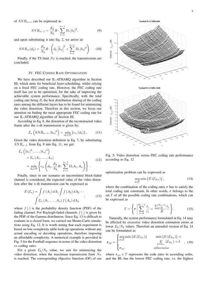
where f (·) is the probability density function (PDF) of thefading channel. For Rayleigh-faded channels f (·) is given bythe PDF of the Gamma distribution. Since Eq. 13 is difficult toevaluate in a closed form, we carried out Monte-Carlo simula-tions using Eq. 12. It is worth noting that each experiment isbased on low-complexity table-look-up operations without anyactual encoding or decoding operations, therefore imposingan affordable complexity. A numerical example is provided inFig. 5 for the Football sequence in terms of the video distortionvs coding rates.
For a given Eb/N0 value, we aim for minimizing thevideo distortion, when the maximum transmission limit NT
is reached. The corresponding objective function (OF) of our
1
0.9
0.8
0.7
0.6
Football R=1/2 SNR=8dB
r0
0.5
0.4
0.30.3
0.4
0.5
r1
0.6
0.7
0.8
0.9
0
5
10
15
1
Dis
tort
ion
ξN
T=
3(d
B)
1
0.9
0.8
0.7
0.6
Football R=1/2 SNR=10dB
r0
0.5
0.4
0.30.3
0.4
0.5
r1
0.6
0.7
0.8
0.9
5
0
1
2
3
4
6
7
8
9
10
1
Dis
tort
ion
ξN
T=
3(d
B)
Fig. 5: Video distortion versus FEC coding rate performanceaccording to Eq. 12
optimization problem can be expressed as
argr∈Γ
min {E (ENT)} , (14)
where the combination of the coding rates r has to satisfy thetotal coding rate constraint. In other words, r belongs to theset Γ of all the possible coding rate combinations, which canbe expressed as
Γ =
{r
∣∣∣∣∣NL−1∑i=0
`iri
=
∑NL−1i=0 `iR
}. (15)
Naturally, the system performance formulated in Eq. 14 maybe affected by excessive video distortion estimation errors atlower Eb/N0 values. Therefore an amended version of Eq. 14can be formulated as
rop =
argr∈Γ
min {E (ENT)} min {E (ENT
)} <E
r=ras
(ENT) + δ
ras otherwise
, (16)
where ras ∈ Γ represents the code rates in ascending order,and the BL has the lowest FEC coding rate, i.e. the highest

9
protection. Still referring to Eq. 16, δ is the estimation errortolerance threshold, which is found experimentally.
To evaluate the effect of the value of δ on the final PSNRperformance of the system, we carried out simulations forvarious settings of δ, and the corresponding PSNR results areshown in Fig. 6. We can observe from Fig. 6a for NT = 3using the Football sequence that the PSNR performance isnot very sensitive to the δ values at high Eb/N0 values, sayfor 13~16 dB. However, a slight improvement of PSNR canbe observed for lower Eb/N0 values around the δ values of0.5 dB. Similar trends can also be observed for NT = 4 inFig. 6b, except that a marginal PSNR reduction is encounteredupon increasing δ at Eb/N0 values above 10 dB. Since theestimation error ENT
is difficult to model analytically, wefound the optimum value of δ experimentally. In order toimprove the PSNR performance at lower Eb/N0 values, weset δ = 0.6 for our simulations, which was also found tobe beneficial for the other video sequences investigated inSection. V.
V. SYSTEM PERFORMANCE
In this section, we will quantify the attainable performancegain of our proposed ATHARQ-IL transmission scheme, aswell as the additional performance gain of our rate-optimizedATHARQ-IL scheme. Furthermore, we will characterize boththe delay performance and the robustness of the aforemen-tioned systems against channel prediction errors. The mainsystem parameters are listed in Table I. Three 4:2:0 YUVformat video sequences were chosen for transmissions, namelythe Football, the Soccer and the Crew video clips. The 15-frame Football sequence is in the (176× 144)-pixel quartercommon intermediate format (QCIF) and has a frame rate of15 frames/second (FPS). The other two 60-frame sequences
Football Soccer Crew
Representation YUV 4:2:0
Format QCIF 4CIF 4CIF
Bits Per Pixel 8
FPS 15 60 60
Number of Frames 30 60 60
Video Codec SVC-H.264
GOP 15
Scalability MGS
Bitrate 2297 kbps 15.36 mbps 11.77 mbps
Error-Free PSNR 40.46 dB 42.62 dB 42.82 dB
Error Concealment Frame-Copy
TABLE I: The parameters of the testing video sequences
Regime Coding Rate (r0, r1) Other Parameters
THARQ (1/2, 1/2), R = 1/2
IL-THARQ (1/2, 1/2), R = 1/2 (n0, n1): limit of transmission
times for the video layers
(1/2, 1/2), R = 1/2
IL-ATHARQ (1/3, 1/2), R = 1/2
(1/3, 1/3), R = 1/2
RO-IL- R = 1/2 non-modified
ATHARQ R = 1/2 δ = 0.6 for all the sequences
TABLE II: The regimes with their settings characterized inSection V, where R stands for the overall coding rate of thesystem.
are in the (704× 576)-pixel 4CIF format, and were recordedat 60 FPS.
We use the JSVM H.264/AVC reference video codec as theSVC codec. The video encoder relies on a group of pictures(GOP) duration of 15 frames and the bi-directionally predicted(B) frames are disabled. We enabled the Medium GrainScalability (MGS) [5], [60] feature for encoding the videosequences into three layers with the aid of the standardizedquantization parameters (QP) of 40, 32 and 24, respectively.The average PSNRs achieved by the decoder for differentsequences are 40.46 dB, 42.62 dB and 42.82 dB, respectively.
Based on our configuration of the SVC encoder, each sliceis encoded into three layers and each layer is encapsulated intoa network abstraction layer unit (NALU) [6]. The NALUs aretransmitted sequentially using our proposed system. Shouldthe CRC check of a certain NALU indicate a decoding failure,these NALUs are discarded. The SVC decoder uses the low-complexity error concealment method of frame-copying inorder to compensate for the lost frames.
The RSC code having a code-rate of 1/3 and the generatorpolynomials of [1011, 1101, 1111] is employed as the FECcode in our system. The reconfigurable puncturers employedare capable of adjusting the FEC code rate on a fine scale,ranging from its original 1/3 to 1, thus providing a wide rangeof design options. The FEC encoded signals are BPSK mod-ulated and transmitted through a block-fading non-dispersiveuncorrelated Rayleigh channel. The total coding rate of thesystem is assumed to be 1/2. The channel is static for eachFEC encoded NALU, but it is faded independently betweenNALUs. As we are considering delay-constrained systems,we characterize the attainable performance of the proposedscheme using two scenarios, where either NT = 3 or NT = 4transmissions are allowed in total, respectively. The regimesand their settings characterized in this section are listed inTable II.

10
22
24
26
28
30
32
34
36
38
40
PS
NR
(dB
)
0.0 0.1 0.2 0.3 0.4 0.5 0.6 0.7 0.8 0.9
(dB)
(a) PSNR vs δ with RO-IL-ATHARQ(δ) for Football, NT = 3
22
24
26
28
30
32
34
36
38
40
PS
NR
(dB
)
0.0 0.1 0.2 0.3 0.4 0.5 0.6 0.7 0.8 0.9
(dB)
Eb/N0(dB)=2
Eb/N0(dB)=3
Eb/N0(dB)=4
Eb/N0(dB)=5
Eb/N0(dB)=6
Eb/N0(dB)=7
Eb/N0(dB)=8
Eb/N0(dB)=9
Eb/N0(dB)=10
Eb/N0(dB)=11
Eb/N0(dB)=12
Eb/N0(dB)=13
Eb/N0(dB)=14
Eb/N0(dB)=15
Eb/N0(dB)=16
(b) PSNR vs δ with RO-IL-ATHARQ(δ) for Football, NT = 4
Fig. 6: PSNR versus δ performance with RO-IL-ATHARQ(δ) systems. The Football sequence was transmitted over block-fadingnon-dispersive uncorrelated Rayleigh channels
SNR Ia r Ie p(l)
......
......
...10.6 0.834 0.93 0.206 110.6 0.834 0.94 0.257 110.6 0.834 0.95 0.333 0.99310.6 0.834 0.96 0.409 0.97310.6 0.834 0.97 0.527 0.8810.6 0.834 0.98 0.687 0.53310.6 0.834 0.99 0.851 0.207...
......
......
TABLE III: Example of the LUT Tp(SNR, Is, r).
A. Off-line LUTs Generation
As described in Eq. 4 of Section III, the estimation of thePER relies on the LUT Tp. Here we describe the implemen-tation of the LUT Tp that is used in our experiments. Asmentioned in Section III, the LUT Tp is indexed by threeparameters, namely SNR, Ia, r. To generate Tp, we fix theblock-length ` of the FEC and obtain the outputs, namely theextrinsic information Ie and the PER p (`) of the componentFEC by scanning the practical coding parameter ranges ofSNR, Ia, r at certain intervals. Specifically, the SNR isconsidered over the range of [0, 25] dB, using a step-size of0.2 dB, Ia is scanned over the range of [0, 1] at intervals of0.01, and finally r is scanned across the range of [0.33, 1] atintervals of 0.02. This makes the total number of legitimatesettings nTp = nsnrnInr = 126×101×33, which is 419,958.All 5 items corresponding to each setting can be individuallystored as floats in 8 bytes. Thus the total size of the LUT Tpis 16 MB. In Table III, we show an example of the LUT Tpthat is used in our simulations.
B. Performance of the Adaptive Rate Controller
In order to demonstrate the attainable performance gain ofour IL-ATHARQ algorithm, we compare its PSNR perfor-mance to that of the aforementioned traditional THARQ aswell as to that of the IL-THARQ scheme relying on fixedtransmission limits, using the Football sequence, as listed inTable I. For the IL-THARQ scheme, we use the compact formof IL-THARQ(n0, n1) to represent different configurations,where n0 and n1 denote the number of transmission timesallowed for L0 and L1, respectively. Since the total numberof transmission is fixed to NT , L2 is allowed to transmit aslong as L0 and L1 have completed their transmission, providedthat the total transmission attempts NT has not been exceeded.At this stage we assume that all the three video layers areencoded using the same FEC coding rate of 1/2, which is thetotal coding rate of the system. The corresponding results areshown in Fig. 7.
Observe in Fig. 7 that the PSNR versus Eb/N0 perfor-mances of our proposed IL-ATHARQ system, relying onNT = 3 or NT = 4 transmissions are portrayed separatelyin Fig. 7a and Fig. 7b. Observe in Fig. 7a that the IL-THARQ(n0, n1) schemes perform differently for the differentconfigurations of n0 and n1, given NT = 3. We opted forcharacterizing the most typical combinations of n0 and n1,noting that others have similar results, hence we limited thenumber of combinations to make the figure more readable.It is clear from Fig. 7a that the IL-THARQ(0, n1) classof systems performs relatively poorly at low Eb/N0 values,because the BL L0 is never transmitted, and the recovery ofL0 solely depends on the accumulation of the MI providedby the information embedded in L1, which is not necessarilybeneficial, given the limited number of transmission slots.However, this drawback turns into a benefit, when the Eb/N0
value reaches higher levels, where L0 can be readily recoveredwith the aid of L1 and the remaining TSs can be savedfor transmitting other layers for the sake of improving the

11
25
30
35
40
PS
NR
(dB
)
5 10 15 20 25
Eb/N0(dB)
THARQ
IL-THARQ(0 2)
IL-THARQ(0 3)
IL-THARQ(1 1)
IL-THARQ(1 2)
IL-THARQ(2 1)
IL-THARQ(2 3)
IL-THARQ(3 1)
IL-ATHARQ
(a) PSNR vs Eb/N0 for Football with NT = 3
25
30
35
40
PS
NR
(dB
)5 10 15 20 25
Eb/N0(dB)
THARQ
IL-THARQ(0 2)
IL-THARQ(0 3)
IL-THARQ(0 4)
IL-THARQ(1 1)
IL-THARQ(1 2)
IL-THARQ(1 3)
IL-THARQ(2 2)
IL-THARQ(3 1)
IL-ATHARQ
(b) PSNR vs Eb/N0 for Football with NT = 4
Fig. 7: PSNR versus Eb/N0 performance of our proposed IL-ATHARQ system versus both the traditional THARQ transmissionand the IL-HARQ scheme in conjunction with fixed transmission limits (IL-THARQ(n0, n1)) as benchmarks. The Footballsequence is used for transmission over block-faded non-dispersive uncorrelated Rayleigh channels
video quality. The traditional THARQ scheme performs betterthan the IL-THARQ(n0, n1) schemes at low levels of Eb/N0
because this scheme prioritizes the transmission of L0 andindeed, recovers L0 with a high probabiliry. However, thisscheme is not so efficient at high Eb/N0 values, becauseeach layer is transmitted at least once, which is not alwaysnecessary in IL-based schemes, since the skipped layer canbe recovered later using the information embedded into theother layers. Compared to the benchmarks, our proposed IL-ATHARQ scheme results in an improved performance byvirtue of its adaptive nature. As observed in Fig. 7a, the IL-ATHARQ scheme outperforms the traditional THARQ schemeall the way and achieves an Eb/N0 reduction of about 3.8dB at a PSNR of 38.5 dB. Alternatively, 1.8 dB of PSNRvideo quality improvement may be observed at an Eb/N0 of15 dB. Furthermore, IL-ATHARQ also outperforms most IL-THARQ(n0, n1) schemes, except for the IL-THARQ(0, 3)scheme, which shows an exceptionally good performance atsufficiently high Eb/N0 values and slightly outperforms IL-ATHARQ. This may be due to the inaccuracy of the distortionestimation function invoked by IL-ATHARQ. Nonetheless, anapproximately 1.9 dB of power reduction is achieved by theIL-ATHARQ arrangement compared to the IL-THARQ(0, 3)scheme at a PSNR of 38.5 dB. Alternatively, about 1.1 dBof PSNR video quality improvement may be observed at anEb/N0 of 15 dB, compared to the IL-THARQ(2, 1) scheme,which is the best performer amongst the IL-THARQ(n0, n1)schemes at an Eb/N0 of 15 dB.
Similarly, observe from Fig. 7b that given NT = 4,the IL-ATHARQ scheme outperforms the traditional THARQarrangement and achieves an Eb/N0 reduction of about 2.7dB at a PSNR of 38.5 dB. Alternatively, about 1.9 dB of
PSNR video quality improvement may be observed at anEb/N0 of 11 dB. IL-ATHARQ outperforms all of the IL-THARQ(n0, n1) schemes at all the Eb/N0 values considered.More specifically, about 1.5 dB of power reduction is achievedby the IL-ATHARQ scheme compared to the IL-THARQ(1,3) scheme at a PSNR of 38.5 dB. Alternatively, about 1.0 dBof PSNR video quality improvement may be observed at anEb/N0 of 11 dB compared to the IL-THARQ(1, 3) scheme,which is the best performance amongst the IL-THARQ(n0, n1)schemes at the Eb/N0 of 11 dB. Generally speaking, the videoperformance gain becomes relatively modest upon increasingNT = 3 to NT = 4. This is because the adaptive schedulingof the layers becomes less important, when there are sufficientTSs.
C. Optimized Coding RatesIn order to characterize the PSNR versus Eb/N0 perfor-
mance both of our proposed RO-IL-ATHARQ system and ofthe modified RO-IL-ATHARQ scheme, we compare them totwo benchmarks, namely to a fixed-rate IL-ATHARQ schemeand to traditional THARQ transmission over block-fading non-dispersive uncorrelated Rayleigh channels, as listed in TableII. These comparisons are shown in Fig. 8, which were carriedout using three different video sequences, namely the Football,the Soccer and the Crew sequences, as listed in Table I.Three different IL-ATHARQ transmission schemes denotedby Rate (r0, r1) were simulated, namely the Rate (1/2, 1/2),the Rate (1/3, 1/2) and the Rate (1/3, 1/3) schemes, where theRate (1/2, 1/2) scheme is the same as the IL-ATHARQ schemewe used in Section V-B.
The results recorded for the Football sequence with theaid of three transmission TSs are shown in Fig. 8a. It can

12
28
30
32
34
36
38
40
PS
NR
(dB
)
5 10 15 20 25
Eb/N0(dB)
Rate(1/2 1/2) THARQ
Rate(1/2 1/2) IL-ATHARQ
Rate(1/3 1/2) IL-ATHARQ
Rate(1/3 1/3) IL-ATHARQ
RO-IL-ATHARQ
RO-IL-ATHARQ(0.6)
(a) PSNR vs Eb/N0 for Football with NT = 3
28
30
32
34
36
38
40
PS
NR
(dB
)
5 10 15 20 25
Eb/N0(dB)
Rate(1/2 1/2) THARQ
Rate(1/2 1/2) IL-ATHARQ
Rate(1/3 1/2) IL-ATHARQ
Rate(1/3 1/3) IL-ATHARQ
RO-IL-ATHARQ
RO-IL-ATHARQ(0.6)
(b) PSNR vs Eb/N0 for Football with NT = 4
28
30
32
34
36
38
40
42
44
PS
NR
(dB
)
5 10 15 20 25
Eb/N0(dB)
Rate(1/2 1/2) THARQ
Rate(1/2 1/2) IL-ATHARQ
Rate(1/3 1/2) IL-ATHARQ
Rate(1/3 1/3) IL-ATHARQ
RO-IL-ATHARQ
RO-IL-ATHARQ(0.6)
(c) PSNR vs Eb/N0 for Soccer with NT = 3
28
30
32
34
36
38
40
42
44
PS
NR
(dB
)
5 10 15 20 25
Eb/N0(dB)
Rate(1/2 1/2) THARQ
Rate(1/2 1/2) IL-ATHARQ
Rate(1/3 1/2) IL-ATHARQ
Rate(1/3 1/3) IL-ATHARQ
RO-IL-ATHARQ
RO-IL-ATHARQ(0.6)
(d) PSNR vs Eb/N0 for Soccer with NT = 4
28
30
32
34
36
38
40
42
44
PS
NR
(dB
)
5 10 15 20 25
Eb/N0(dB)
Rate(1/2 1/2) THARQ
Rate(1/2 1/2) IL-ATHARQ
Rate(1/3 1/2) IL-ATHARQ
Rate(1/3 1/3) IL-ATHARQ
RO-IL-ATHARQ
RO-IL-ATHARQ(0.6)
(e) PSNR vs Eb/N0 for Crew with NT = 3
28
30
32
34
36
38
40
42
44
PS
NR
(dB
)
5 10 15 20 25
Eb/N0(dB)
Rate(1/2 1/2) THARQ
Rate(1/2 1/2) IL-ATHARQ
Rate(1/3 1/2) IL-ATHARQ
Rate(1/3 1/3) IL-ATHARQ
RO-IL-ATHARQ
RO-IL-ATHARQ(0.6)
(f) PSNR vs Eb/N0 for Crew with NT = 4
Fig. 8: PSNR versus Eb/N0 performance of our proposed RO-IL-ATHARQ system and of the modified RO-IL-ATHARQscheme in comparison to both the IL-ATHARQ transmission and to the traditional THARQ transmission as benchmarks. TheFootball, Soccer and Crew sequences are used for transmission over block-fading non-dispersive uncorrelated Rayleigh channels

13
Fig. 9: Comparison of decoded frames of the 26-th frame at Eb/N0 of 10 dB for the Soccer sequences and NT = 3. The upperfive columns (from left to right) indicate frames of the original video, the rate(1/2, 1/2) IL-THARQ(1 1) scheme, rate(1/2, 1/2)THARQ scheme, the rate(1/2, 1/2) IL-ATHARQ scheme and the RO-IL-ATHARQ(0.6) scheme, respectively. The lower rowcorrespond to the difference frames between the top ones and the original video frame.
be observed that all the fixed-rate IL-ATHARQ transmissionschemes outperformed the pure THARQ transmission. TheRO-IL-ATHARQ scheme outperforms all other schemes athigh Eb/N0 values, but its performance becomes inferior tothe Rate (1/3, 1/3) IL-ATHARQ scheme below the Eb/N0
value of 10 dB, owing to the inaccurate distortion estima-tion. However, when the modified RO-IL-ATHARQ schemeassociated with δ = 0.6 is adopted, the system outperformsthe other schemes at lower Eb/N0 values, and achieves anEb/N0 reduction of about 5.3 dB at a PSNR of 38.5 dB,over the THARQ benchmark. This represents an additional1.5 dB of Eb/N0 reduction compared to the Rate (1/2, 1/2)IL-ATHARQ scheme used in Section V-B. Alternatively, about2.5 dB of PSNR video quality improvement may be observedat an Eb/N0 of 15 dB, which is an additional 0.7 dB of PSNRimprovement compared to the Rate (1/2, 1/2) IL-ATHARQscheme.
Given NT = 4, Fig. 8b shows a slightly different trend,where the different fixed-rate IL-ATHARQ schemes exhibit abetter performance over certain Eb/N0 regions. Specifically,the Rate (1/2, 1/2) scheme outperforms the rest for Eb/N0
values above 8 dB, while the Rate (1/3, 1/3) scheme per-forms better below Eb/N0 of 5 dB and the Rate (1/3, 1/2)regime excels in the region between 5 and 8 dB. Again,we can observe that the modified RO-IL-ATHARQ schemeassociated with δ = 0.6 outperforms all the fixed-rate IL-ATHARQ schemes across the entire Eb/N0 region we areinterested in. It achieves a similar Eb/N0 reduction as theRate (1/2, 1/2) IL-ATHARQ at a PSNR of 38.5 dB. However,a 2.4 dB of Eb/N0 reduction is observed at a PSNR of 30dB, while only 0.5 dB of Eb/N0 reduction is attained by theRate (1/2, 1/2) IL-ATHARQ. Alternatively, about 4.7 dB ofvideo PSNR improvement may be observed at an Eb/N0 of 4dB, while only 0.8 dB of PSNR improvement is achieved bythe Rate (1/2, 1/2) IL-ATHARQ.
Similar trends can be observed, when the Soccer or Crewsequences are used, as shown in Fig. 8c to Fig. 8f. Weinfer from these results that our RO-IL-ATHARQ scheme isapplicable to video sequences of diverse natures, and it is
capable of achieving a beneficial performance gain for bothNT = 3 and 4. The subjective comparison of the decodedvideos associated with our different regimes is discussed inSection V-D.
D. Subjective Comparison
Explicitly, Fig. 9 shows the subjective comparison of thedecoded video frames associated with our different regimesusing the Soccer sequence and NT = 3 at the Eb/N0
value of 10 dB. The 26-th frame of the recovered videos ofsome of our schemes are shown in the top row of Fig. 9.The rate(1/2, 1/2) IL-THARQ(1 1) scheme is more error-proneaccording to Section V-B, and in this regime all three layers ofthis frame failed to be recovered, and so did all their precedingframes. The difference frame, which is obtained by subtractingthe recovered frame from the 26-th frame of the originalvideo, has substantial non-zero values. Continuing from leftto right, we can observe that the frames corresponding to therate(1/2, 1/2) THARQ scheme, the rate(1/2, 1/2) IL-ATHARQscheme and the RO-IL-ATHARQ(0.6) scheme are becomingsharper and containing more intricate video details, while thecorresponding difference frames having less and less non-zerovalues, which indicates the improvement of the video quality.
E. Transmission Delay
In Fig. 10, the average number of TSs required for receiv-ing the i-th layer employing various transmission schemesis displayed. When NT = 3 is used, the average numberof TSs versus the Eb/N0 characteristics are shown in Fig.10a. When the Rate (1/2, 1/2) THARQ, Rate (1/2, 1/2) IL-ATHARQ and Rate (1/3, 1/2) IL-ATHARQ schemes are usedalong with NT = 3, three TSs are occupied, regardless ofthe Eb/N0 value. On the other hand, observe in Fig. 10athat the Rate (1/3, 1/3) IL-ATHARQ, RO-IL-ATHARQ andRO-IL-ATHARQ(0.6) schemes only use two TSs on average,in order to successfully receive all transmissions at highEb/N0 values. Furthermore, as seen in Fig. 10a, both theRO-IL-ATHARQ(0.6) and RO-IL-ATHARQ schemes require

14
1.0
1.5
2.0
2.5
3.0
Del
ay(T
)
-5 0 5 10 15 20 25 30
Eb/N0(dB)
300-frame-Football sequence, FPS=30, CIF
Rate(1/2 1/2) THARQ
Rate(1/2 1/2) IL-ATHARQ
Rate(1/3 1/2) IL-ATHARQ
Rate(1/3 1/3) IL-ATHARQ
RO-IL-ATHARQ
RO-IL-ATHARQ(0.6)
L0
L0, L1
L0, L1, L2
(a) Average time slots used vs Eb/N0 for Football, NT = 3
1.0
1.5
2.0
2.5
3.0
3.5
4.0
Del
ay(T
)
-5 0 5 10 15 20 25 30
Eb/N0(dB)
300-frame-Football sequence, FPS=30, CIF
Rate(1/2 1/2) THARQ
Rate(1/2 1/2) IL-ATHARQ
Rate(1/3 1/2) IL-ATHARQ
Rate(1/3 1/3) IL-ATHARQ
RO-IL-ATHARQ
RO-IL-ATHARQ(0.6)
L0
L0, L1
L0, L1, L2
(b) Average time slots used vs Eb/N0 for Football, NT = 4
Fig. 10: Average transmission time slots versus Eb/N0 performance comparison of the THARQ, IL-ATHARQ, RO-IL-ATHARQ, and modified RO-IL-ATHARQ schemes for the Football sequence, transmitted over the quasi-static non-dispersiveuncorrelated Rayleigh fading wireless channels
slightly less transmission TSs than the Rate (1/3, 1/3) IL-ATHARQ at the same Eb/N0 value. It can also be ob-served in Fig. 10a that for the first two layers, namely forL0 and L1, the Rate (1/2, 1/2) THARQ, Rate (1/2, 1/2) IL-ATHARQ and Rate (1/3, 1/2) IL-ATHARQ schemes requiretwo TSs on average at sufficiently high Eb/N0 values, whilethe Rate (1/3, 1/3) IL-ATHARQ, RO-IL-ATHARQ and RO-IL-ATHARQ(0.6) schemes only need one TS. It can also beinferred from Fig. 10a that the rate-optimized schemes occupymore TSs by successfully conveying L0 and L1. The reasonbehind this phenomenon is that the optimization algorithmstrikes a more balanced compromise instead of assigning allthe resources for protecting L0 and L1, where a reasonablereduction of the protection of L1 can be compensated bysuccessfully decoding both L1 and L2 in a single reception,if the latter one is well protected and ends up possessinghigh MI values. Finally, if we consider the transmissionof L0, we find from Fig. 10a that the Rate (1/3, 1/2) andRate (1/3, 1/3) IL-ATHARQ, as well as the RO-IL-ATHARQand RO-IL-ATHARQ(0.6) generally necessitates less transmis-sion TSs, than the Rate (1/2, 1/2) THARQ and Rate (1/2, 1/2)IL-ATHARQ.
In Fig. 10b, the average number of TSs used versus theEb/N0 is portrayed for NT = 4. Similar trends can beobserved to those recorded in Fig. 10a for NT = 3. Hencewe conclude that the IL-ATHARQ is capable of efficientlyreducing the number of TSs required for transmission, and theRO-IL-ATHARQ, although optimized for minimum distortion,additionally occupies less TSs.
F. Effect of Channel Prediction Errors
To demonstrate the effect of the channel prediction errorson the performance of our proposed system, we includethe simulation results for both the IL-ATHARQ and RO-IL-ATHARQ(0.6) transmission schemes contaminated by channelprediction errors [58] in Fig. 11, which obeyed a Gaussiandistribution.
As shown in Fig. 11a, the performance of the Rate (1/2, 1/2)IL-ATHARQ degrades with the increase of σ2
e of the channelprediction error. The PSNR performance was affected predom-inantly in the lower Eb/N0 range by the channel predictionerror. For example, at the Eb/N0 of 6 dB, the PSNR associatedwith σ2
e = 0.5 is 1.35 dB lower than the one relying onperfect channel prediction, while the system’s performancewith σ2
e = 4 is 3.35 dB worse. At the Eb/N0 of 11 dB,the PSNR performance associated with σ2
e = 0.5 is 1.5 dBworse than the one with perfect channel prediction, while thatin conjunction with σ2
e = 4 is 1 dB worse. The IL-ATHARQschemes still exhibit a performance gain over the THARQbenchmark system for Eb/N0 values above 8 dB.
As for the performance of the RO-IL-ATHARQ system,we can observe in Fig. 11b that the channel prediction erroraffected the systems more severely than for the IL-ATHARQsystems. At the Eb/N0 of 6 dB, the PSNR performanceassociated with σ2
e = 0.5 is 2.4 dB worse than that of perfectchannel prediction, while the system performance relying onσ2e = 4 is 6.1 dB worse. At the Eb/N0 of 11 dB, the PSNR
performance of σ2e = 0.5 is 1 dB lower than the one with
perfect channel prediction, while that associated with σ2e = 4 is
2.6 dB worse. The system’s performance recorded for σ2e = 2
or σ2e = 4 is even worse than that of the THARQ benchmark

15
25
30
35
40
PS
NR
(dB
)
2 4 6 8 10 12 14 16
Eb/N0(dB)
300-frame-Football sequence, FPS=30, CIF
Accurate, Rate(1/2,1/2) IL-ATHARQ
Rate(1/2,1/2) THARQ
e2=0.05, Rate(1/2,1/2) IL-ATHARQ
e2=0.2, Rate(1/2,1/2) IL-ATHARQ
e2=0.5, Rate(1/2,1/2) IL-ATHARQ
e2=2, Rate(1/2,1/2) IL-ATHARQ
e2=4, Rate(1/2,1/2) IL-ATHARQ
(a) PSNR vs Eb/N0 with IL-ATHARQ for Football, NT = 4
25
30
35
40
PS
NR
(dB
)
2 4 6 8 10 12 14 16
Eb/N0(dB)
300-frame-Football sequence, FPS=30, CIF
Accurate, RO-IL-ATHARQ
Rate(1/2,1/2) THARQ
e2=0.05, RO-IL-ATHARQ
e2=0.2, RO-IL-ATHARQ
e2=0.5, RO-IL-ATHARQ
e2=2, RO-IL-ATHARQ
e2=4, RO-IL-ATHARQ
(b) PSNR vs Eb/N0 with RO-IL-ATHARQ for Football,NT = 4
Fig. 11: PSNR versus Eb/N0 performance in the presence ofchannel prediction errors, which affected the Rate (1/2, 1/2)IL-ATHARQ, RO-IL-ATHARQ system for different σ2
e valuesagainst that of the THARQ system used as the benchmark.
system due to the severe error propagation imposed by thechannel prediction. We may observe that in Fig. 11b thePSNR performance achieved with the aid of perfect channelprediction is not substantially better than the one associatedwith σ2
e = 0.05, when we have Eb/N0 ≤ 6 dB. Recall that theunmodified RO-IL-ATHARQ scheme of Section IV is subjectto a certain level of PER estimation errors introduced by thealgorithm itself and it is even more so in conjunction withlarger NT values because of the error propagation. The effectof the channel estimation error may be deemed comparableto that of the PER estimation errors, provided that it is notexcessive. The interaction of these two types of errors maynot be additive.
VI. CONCLUSIONS
We conceived an adaptive THARQ (ATHARQ) algorithmfor IL-FEC coded layered video streaming for the sake ofminimizing the video distortion under the constraint of a giventotal number of transmission TSs. The adaptive retransmissioncontroller predicts the channel conditions and estimates theSNR values at the receiver for the sake of appropriatelyconfiguring the transmitter. The specific video layer, whichwould most effectively reduce the video distortion at thereceiver is chosen for transmission. Furthermore, we devel-oped an on-line optimization technique for our IL-ATHARQtransmission scheme, in order to find the most beneficial FECcode rate for each of the video layers that results in a reducedvideo distortion. A method of estimating the video distortionsrelated to each code rate assignment was conceived for theIL-ATHARQ transmission.
Our simulation results demonstrated that the optimized IL-FEC system outperforms the traditional THARQ system byan Eb/N0 value of about 5.3 dB at a PSNR of 38.5 dB. Al-ternatively, about 2.5 dB of PSNR video quality improvementmay be observed at an Eb/N0 of 15 dB, when employing aRSC code.
In our future work, we will further develop our THARQscheme for incremental redundancy aided schemes.
REFERENCES
[1] L. Hanzo, P. Cherriman, and J. Streit, Video Compression and Commu-nications: From Basics to H.261, H.263, H.264, MPEG2, MPEG4 forDVB and HSDPA-Style Adaptive Turbo-Transceivers. New York: JohnWiley, 2007.
[2] T. Zhang and Y. Xu, “Unequal packet loss protection for layered videotransmission,” IEEE Transactions on Broadcasting, vol. 45, pp. 243–252, June 1999.
[3] L. Zhang, G. Tech, K. Wegner, and S. Yea, “Test model 6 of 3D-HEVCand MV-HEVC,” vol. N13940, ISO/IEC JTC-1/SC29/WG11, November2013.
[4] H. Imaizumi and A. Luthra, Three-Dimensional Television, Video andDisplay Technologies, ch. MPEG-2 Multiview Profile, pp. 169–181.Berlin, Heidelberg, and New York: Springer Verlag, 2002.
[5] H. Schwarz, D. Marpe, and T. Wiegand, “Overview of the scalable videocoding extension of the H.264/AVC standard,” IEEE Transactions onCircuits and Systems for Video Technology, vol. 17, pp. 1103–1120,September 2007.
[6] Joint Video Team (JVT) of ISO/IEC MPEG and ITU-T VCEG, ITU-T Rec. H.264/ISO/IEC 14496-10 AVC: Advanced Video Coding forGeneric Audiovisual Services, March 2010.
[7] A. Vetro, T. Wiegand, and G. Sullivan, “Overview of the stereo and mul-tiview video coding extensions of the H.264/MPEG-4 AVC standard,”Proceedings of the IEEE, vol. 99, pp. 626–642, April 2011.
[8] J. Boyce, W. Jang, D. Hong, S. Wenger, Y.-K. Wang, and Y. Chen,“High level syntax hooks for future extensions,” in JCT-VC document,vol. JCTVC-H0388, (San Josà c©, CA, USA), February 2012.
[9] A. Segall, “BoG report on SHVC,” in JCT-VC document, vol. JCTVC-K0354, (Shanghai, China), October 2012.
[10] D. Chase, “A combined coding and modulation approach for commu-nication over dispersive channels,” IEEE Transactions on Communica-tions, vol. 21, pp. 159–174, March 1973.
[11] I. Stanojev, O. Simeone, Y. Bar-Ness, and D. H. Kim, “Energy efficiencyof non-collaborative and collaborative hybrid-ARQ protocols,” IEEETransactions on Wireless Communications, vol. 8, pp. 326–335, January2009.
[12] J. Ramis and G. Femenias, “Cross-layer design of adaptive multiratewireless networks using truncated HARQ,” IEEE Transactions on Ve-hicular Technology, vol. 60, pp. 944–954, March 2011.
[13] J. Ramis, G. Femenias, F. Riera-Palou, and L. Carrasco, “Cross-layeroptimization of adaptive multi-rate wireless networks using truncatedchase combining HARQ,” in IEEE Global Telecommunications Confer-ence (GLOBECOM), pp. 1–6, December 2010.

16
[14] T. Kwon and D.-H. Cho, “Adaptive-modulation-and-coding-based trans-mission of control messages for resource allocation in mobile commu-nication systems,” IEEE Transactions on Vehicular Technology, vol. 58,pp. 2769–2782, July 2009.
[15] Q. Zhang and S. Kassam, “Hybrid ARQ with selective combining forfading channels,” IEEE Journal on Selected Areas in Communications,vol. 17, pp. 867–880, May 1999.
[16] A. Majumda, D. Sachs, I. Kozintsev, K. Ramchandran, and M. Yeung,“Multicast and unicast real-time video streaming over wireless LANs,”IEEE Transactions on Circuits and Systems for Video Technology,vol. 12, pp. 524–534, June 2002.
[17] Q. Zhang, Q. Guo, Q. Ni, W. Zhu, and Y.-Q. Zhang, “Sender-adaptiveand receiver-driven layered multicast for scalable video over the inter-net,” IEEE Transactions on Circuits and Systems for Video Technology,vol. 15, pp. 482–495, April 2005.
[18] Z. Liu, Z. Wu, P. Liu, H. Liu, and Y. Wang, “Layer bargaining: multicastlayered video over wireless networks,” IEEE Journal on Selected Areasin Communications, vol. 28, pp. 445–455, April 2010.
[19] M. Wu, S. Makharia, H. Liu, D. Li, and S. Mathur, “IPTV multicastover wireless LAN using merged hybrid ARQ with staggered adaptiveFEC,” IEEE Transactions on Broadcasting, vol. 55, pp. 363–374, June2009.
[20] I. Bajic, “Efficient cross-layer error control for wireless video multicast,”IEEE Transactions on Broadcasting, vol. 53, pp. 276–285, March 2007.
[21] B. Masnick and J. Wolf, “On linear unequal error protection codes,”IEEE Transactions on Information Theory, vol. 13, pp. 600–607, Octo-ber 1967.
[22] Y. Wu, S. Kumar, F. Hu, Y. Zhu, and J. Matyjas, “Cross-layer forwarderror correction scheme using raptor and RCPC codes for prioritizedvideo transmission over wireless channels,” IEEE Transactions onCircuits and Systems for Video Technology, vol. 24, pp. 1047–1060,June 2014.
[23] A. A. Khalek, C. Caramanis, and R. W. Heath, “A cross-layer design forperceptual optimization of H.264/SVC with unequal error protection,”IEEE Journal on Selected Areas in Communications, vol. 30, no. 7,pp. 1157–1171, 2012.
[24] J. Park, H. Lee, S. Lee, and A. Bovik, “Optimal channel adaptation ofscalable video over a multicarrier-based multicell environment,” IEEETransactions on Multimedia, vol. 11, pp. 1062–1071, October 2009.
[25] H. Wang, F. Zhai, Y. Eisenberg, and A. Katsaggelos, “Cost-distortionoptimized unequal error protection for object-based video communica-tions,” IEEE Transactions on Circuits and Systems for Video Technology,vol. 15, pp. 1505–1516, December 2005.
[26] H. Ha and C. Yim, “Layer-weighted unequal error protection forscalable video coding extension of H.264/AVC,” IEEE Transactions onConsumer Electronics, vol. 54, pp. 736–744, May 2008.
[27] D. Sejdinovic, D. Vukobratovic, A. Doufexi, V. Šenk, and R. Piechocki,“Expanding window fountain codes for unequal error protection,” IEEETransactions on Communications, vol. 57, pp. 2510–2516, November2009.
[28] D. Vukobratovic, V. Stankovic, D. Sejdinovic, L. Stankovic, andZ. Xiong, “Scalable video multicast using expanding window fountaincodes,” IEEE Transactions on Multimedia, vol. 11, pp. 1094–1104,October 2009.
[29] E. Maani and A. Katsaggelos, “Unequal error protection for robuststreaming of scalable video over packet lossy networks,” IEEE Trans-actions on Circuits and Systems for Video Technology, vol. 20, pp. 407–416, March 2010.
[30] S. Ahmad, R. Hamzaoui, and M. Al-Akaidi, “Unequal error protectionusing fountain codes with applications to video communication,” IEEETransactions on Multimedia, vol. 13, pp. 92–101, February 2011.
[31] K. Nguyen, T. Nguyen, and S.-C. Cheung, “Video streaming withnetwork coding,” Journal of Signal Processing Systems, vol. 59, pp. 319–333, June 2010.
[32] M. Halloush and H. Radha, “Network coding with multi-generationmixing: A generalized framework for practical network coding,” IEEETransactions on Wireless Communications, vol. 10, pp. 466–473, Febru-ary 2011.
[33] F. Marx and J. Farah, “A novel approach to achieve unequal errorprotection for video transmission over 3G wireless networks,” SignalProcessing: Image Communication, vol. 19, pp. 313–323, April 2004.
[34] S. X. Ng, J. Y. Chung, and L. Hanzo, “Turbo-detected unequal protectionMPEG-4 wireless video telephony using multi-level coding, trellis codedmodulation and space-time trellis coding,” IEE Proceedings Communi-cations, vol. 152, pp. 1116–1124, December 2005.
[35] M. Aydinlik and M. Salehi, “Turbo coded modulation for unequal errorprotection,” IEEE Transactions on Communications, vol. 56, pp. 555–564, April 2008.
[36] Y. C. Chang, S. W. Lee, and R. Komiya, “A fast forward error correctionallocation algorithm for unequal error protection of video transmissionover wireless channels,” IEEE Transactions on Consumer Electronics,vol. 54, pp. 1066–1073, August 2008.
[37] Y. C. Chang, S. W. Lee, and R. Komiya, “A low complexity hierarchicalQAM symbol bits allocation algorithm for unequal error protection ofwireless video transmission,” IEEE Transactions on Consumer Electron-ics, vol. 55, pp. 1089–1097, August 2009.
[38] C. Hellge, D. Gomez-Barquero, T. Schierl, and T. Wiegand, “Layer-aware forward error correction for mobile broadcast of layered media,”IEEE Transactions on Multimedia, vol. 13, pp. 551–562, June 2011.
[39] Nasruminallah and L. Hanzo, “Near-capacity H.264 multimedia commu-nications using iterative joint source-channel decoding,” IEEE Commu-nications Surveys and Tutorials, vol. 14, pp. 538–564, Second Quarter2012.
[40] Y. Huo, M. El-Hajjar, and L. Hanzo, “Inter-layer FEC aided unequalerror protection for multilayer video transmission in mobile TV,” IEEETransactions on Circuits and Systems for Video Technology, vol. 23,pp. 1622–1634, September 2013.
[41] D. Wu, Y. T. Hou, and Y.-Q. Zhang, “Transporting real-time videoover the Internet: challenges and approaches,” Proceedings of the IEEE,vol. 88, pp. 1855–1877, December 2000.
[42] T. Stockhammer, M. Hannuksela, and T. Wiegand, “H.264/AVC inwireless environments,” IEEE Transactions on Circuits and Systems forVideo Technology, vol. 13, pp. 657–673, July 2003.
[43] Y. Huo, M. El-Hajjar, R. Maunder, and L. Hanzo, “Layered wirelessvideo relying on minimum-distortion inter-layer FEC coding,” IEEETransactions on Multimedia, vol. 16, pp. 697–710, April 2014.
[44] Q. Zhang, W. Zhu, and Y.-Q. Zhang, “Channel-adaptive resource allo-cation for scalable video transmission over 3G wireless network,” IEEETransactions on Circuits and Systems for Video Technology, vol. 14,pp. 1049–1063, August 2004.
[45] T. Stockhammer, H. Jenkac, and C. Weiss, “Feedback and error pro-tection strategies for wireless progressive video transmission,” IEEETransactions on Circuits and Systems for Video Technology, vol. 12,pp. 465–482, June 2002.
[46] P. Chou, A. Mohr, A. Wang, and S. Mehrotra, “Error control for receiver-driven layered multicast of audio and video,” IEEE Transactions onMultimedia, vol. 3, pp. 108–122, March 2001.
[47] D. Taubman and J. Thie, “Optimal erasure protection for scalably com-pressed video streams with limited retransmission,” IEEE Transactionson Image Processing, vol. 14, pp. 1006–1019, August 2005.
[48] R. Xiong, D. Taubman, and V. Sivaraman, “Optimal PET protectionfor streaming scalably compressed video streams with limited retrans-mission based on incomplete feedback,” IEEE Transactions on ImageProcessing, vol. 19, no. 9, pp. 2382–2395, 2010.
[49] R. Xiong, D. S. Taubman, and V. Sivaraman, “PET protection optimiza-tion for streaming scalable videos with multiple transmissions,” IEEETransactions on Image Processing, vol. 22, pp. 4364–4379, November2013.
[50] J. Zhang, W. Liang, J. Wu, and D. Shi, “A novel retransmissionscheme for video services in hybrid wireline/wireless networks,” inIEEE Vehicular Technology Conference (VTC-Spring), 71st, pp. 1–5,May 2010.
[51] B. Tirouvengadam, R. Radhakrishnan, and A. Nayak, “CAAHR: Contentaware adaptive HARQ retransmission scheme for 4G/LTE network,” inUbiquitous and Future Networks (ICUFN), 2012 Fourth InternationalConference on, pp. 456–461, July 2012.
[52] A. Le Duc, P. Ciblat, and C. Le Martret, “Analysis of a cross-layerhybrid-ARQ scheme: Application to unequal packet protection,” in IEEEInternational Conference on Communications (ICC), pp. 1–5, June 2011.
[53] A. Albanese, J. Blomer, J. Edmonds, M. Luby, and M. Sudan, “Priorityencoding transmission,” IEEE Transactions on Information Theory,vol. 42, pp. 1737–1744, November 1996.
[54] L. Bahl, J. Cocke, F. Jelinek, and J. Raviv, “Optimal decoding oflinear codes for minimizing symbol error rate,” IEEE Transactions onInformation Theory, vol. 20, pp. 284–287, March 1974.
[55] L. Cheng, B. Henty, D. Stancil, F. Bai, and P. Mudalige, “Mobile vehicle-to-vehicle narrow-band channel measurement and characterization of the5.9 ghz dedicated short range communication (dsrc) frequency band,”Selected Areas in Communications, IEEE Journal on, vol. 25, pp. 1501–1516, October 2007.

17
[56] L. Hanzo, J. Blogh, and S. Ni, 3G, HSPA and FDD versus TDDnetworking : smart antennas and adaptive modulation. Chichester: JohnWiley & Sons [s.l.], 2008.
[57] L. L. Hanzo, Y. Akhtman, L. Wang, and M. Jiang, MIMO-OFDM forLTE, WiFi and WiMAX: Coherent versus Non-coherent and CooperativeTurbo Transceivers. John Wiley & Sons, IEEE press, October 2010.
[58] H. Gacanin, M. Salmela, and F. Adachi, “Performance analysis ofanalog network coding with imperfect channel estimation in a frequency-selective fading channel,” IEEE Transactions on Wireless Communica-tions, vol. 11, pp. 742–750, February 2012.
[59] H. Xiao, Q. Dai, X. Ji, and W. Zhu, “A novel JSCC framework withdiversity-multiplexing-coding gain tradeoff for scalable video trans-mission over cooperative MIMO,” IEEE Transactions on Circuits andSystems for Video Technology, vol. 20, pp. 994–1006, July 2010.
[60] A. Detti, G. Bianchi, C. Pisa, F. Proto, P. Loreti, W. Kellerer, S. Thakol-sri, and J. Widmer, “SVEF: an open-source experimental evaluationframework for H.264 scalable video streaming,” in IEEE Symposiumon Computers and Communications, ISCC, (Sousse, Tunisia), pp. 36–41, July 2009.
Chuan Zhu received the B.Eng. de-gree from Southeast University, Nan-jing, China, and the M.Sc. degree(with distinction) in radio-frequencycommunication systems from the Uni-versity of Southampton, Southamp-ton, U.K., in 2010. He is currentlyworking toward the Ph.D. degree withthe Communications Research Group,School of Electronics and ComputerScience, University of Southampton.
His research interests include joint source–channel decoding,video compression and transmission, and extrinsic informationtransfer chart-aided turbo detection, as well as cooperativecommunications. Mr. Zhu received the Student Case Awardtoward his Ph.D. study from British Telecom, London, U.K.
Yongkai Huo received the B.Eng. de-gree with distinction in computer sci-ence and technology from Hefei Uni-versity of Technology, Hefei, China,in 2006 and the M.Eng. degree incomputer software and theory fromUniversity of Science and Technologyof China, Hefei, China, in 2009. In2014, he was awarded a Ph.D in Wire-less Communications group, Schoolof Electronics and Computer Science,
University of Southampton, Southampton, UK, where heis currently working as a research fellow. He received ascholarship under the China-U.K. Scholarships for ExcellenceProgramme. His research interests include distributed videocoding, multiview video coding, robust wireless video stream-ing and joint source-channel decoding.
Bo Zhang received his B.Eng. de-gree in Information Engineering fromNational University of Defense Tech-nology, China, in 2010. He receivedthe Ph.D. degree in wireless commu-nications from School of Electronicsand Computer Science, University of
Southampton, Southampton, U.K., in2015. His research interests in wire-less communications include designand analysis of cooperative commu-
nications, MIMO and network-coded systems.
Rong Zhang (M’09) received his PhD(Jun 09) from Southampton Univer-sity, UK and his BSc (Jun 03) fromSoutheast University, China. Beforedoctorate, he was an engineer (Aug03-July 04) at China Telecom and aresearch assistant (Jan 06-May 09) atMobile Virtual Center of Excellence(MVCE), UK. After being a post-doctoral researcher (Aug 09-July 12)
at Southampton University, he took industrial consulting leave(Aug 12-Jan 13) for Huawei Sweden R\& D as a systemalgorithms specialist. Since Feb 13, he has been appointedas a lecturer at CSPC group of ECS, Southampton University.He has 40+ journals in prestigious publication avenues (e.g.IEEE, OSA) and many more in major conference proceedings.He regularly serves as reviewer for IEEE transactions/journalsand has been several times as TPC member/invited sessionchair of major conferences. He is the recipient of joint fundingof MVCE and EPSRC and is also a visiting researcher underWorldwide University Network (WUN). More details can befound at http://www.ecs.soton.ac.uk/people/rz
Mohammed El-Hajjar is a lecturerin the Electronics and Computer Sci-ence in the University of Southamp-ton. He received his BEng degree inElectrical Engineering from the Amer-ican University of Beirut, Lebanon in2004. He then received an MSc in Ra-dio Frequency Communication Sys-tems and PhD in Wireless Commu-nications both from the University ofSouthampton, UK in 2005 and 2008,respectively. Following the PhD, he
joined Imagination Technologies as a design engineer, wherehe worked on designing and developing Imagination’s multi-standard communications platform, which resulted in threepatents. In January 2012, he joined the Electronics and Com-puter Science in the University of Southampton as a lecturer inthe Southampton Wireless research group. He is the recipientof several academic awards including the Dean’s award forcreative achievement, Dorothy Hodgkin postgraduate awardand IEEE ICC 2010 Best paper award. He has published aWiley-IEEE book and in excess of 50 journal and internationalconference papers. His research interests are mainly in thedevelopment of intelligent communications systems includingenergy-efficient transceiver design, cross-layer optimisation forlarge-scale networks, MIMO, millimetre wave communica-tions and Radio over fibre systems.

18
Lajos Hanzo (http://www-mobile.ecs.soton.ac.uk) FREng,FIEEE, FIET, Fellow of EURASIP,DSc received his degree in electronicsin 1976 and his doctorate in 1983. In2009 he was awarded the honorarydoctorate “Doctor Honoris Causa”by the Technical University ofBudapest. During his 38-year careerin telecommunications he has held
various research and academic posts in Hungary, Germany andthe UK. Since 1986 he has been with the School of Electronicsand Computer Science, University of Southampton, UK, wherehe holds the chair in telecommunications. He has successfullysupervised about 100 PhD students, co-authored 20 JohnWiley/IEEE Press books on mobile radio communicationstotalling in excess of 10 000 pages, published 1400+ researchentries at IEEE Xplore, acted both as TPC and GeneralChair of IEEE conferences, presented keynote lectures andhas been awarded a number of distinctions. Currently he isdirecting a 100-strong academic research team, working on arange of research projects in the field of wireless multimediacommunications sponsored by industry, the Engineeringand Physical Sciences Research Council (EPSRC) UK, theEuropean Research Council’s Advanced Fellow Grant andthe Royal Society’s Wolfson Research Merit Award. He is anenthusiastic supporter of industrial and academic liaison andhe offers a range of industrial courses. He is also a Governorof the IEEE VTS. During 2008 - 2012 he was the Editor-in-Chief of the IEEE Press and a Chaired Professor also atTsinghua University, Beijing. His research is funded by theEuropean Research Council’s Senior Research Fellow Grant.For further information on research in progress and associatedpublications please refer to http://www-mobile.ecs.soton.ac.ukLajos has 20 000+ citations.